EP4134786B1 - Etui und aufbewahrungsvorrichtung - Google Patents
Etui und aufbewahrungsvorrichtung Download PDFInfo
- Publication number
- EP4134786B1 EP4134786B1 EP21812991.4A EP21812991A EP4134786B1 EP 4134786 B1 EP4134786 B1 EP 4134786B1 EP 21812991 A EP21812991 A EP 21812991A EP 4134786 B1 EP4134786 B1 EP 4134786B1
- Authority
- EP
- European Patent Office
- Prior art keywords
- clamping
- installation frame
- clamping part
- chassis body
- sliding rail
- Prior art date
- Legal status (The legal status is an assumption and is not a legal conclusion. Google has not performed a legal analysis and makes no representation as to the accuracy of the status listed.)
- Active
Links
Images



Classifications
-
- H—ELECTRICITY
- H05—ELECTRIC TECHNIQUES NOT OTHERWISE PROVIDED FOR
- H05K—PRINTED CIRCUITS; CASINGS OR CONSTRUCTIONAL DETAILS OF ELECTRIC APPARATUS; MANUFACTURE OF ASSEMBLAGES OF ELECTRICAL COMPONENTS
- H05K7/00—Constructional details common to different types of electric apparatus
- H05K7/14—Mounting supporting structure in casing or on frame or rack
- H05K7/1485—Servers; Data center rooms, e.g. 19-inch computer racks
- H05K7/1488—Cabinets therefor, e.g. chassis or racks or mechanical interfaces between blades and support structures
-
- G—PHYSICS
- G06—COMPUTING OR CALCULATING; COUNTING
- G06F—ELECTRIC DIGITAL DATA PROCESSING
- G06F1/00—Details not covered by groups G06F3/00 - G06F13/00 and G06F21/00
- G06F1/16—Constructional details or arrangements
- G06F1/18—Packaging or power distribution
- G06F1/181—Enclosures
-
- G—PHYSICS
- G06—COMPUTING OR CALCULATING; COUNTING
- G06F—ELECTRIC DIGITAL DATA PROCESSING
- G06F1/00—Details not covered by groups G06F3/00 - G06F13/00 and G06F21/00
- G06F1/16—Constructional details or arrangements
- G06F1/18—Packaging or power distribution
- G06F1/183—Internal mounting support structures, e.g. for supporting printed circuit boards
- G06F1/185—Mounting of expansion boards
- G06F1/186—Securing of expansion boards in correspondence to slots provided at the computer enclosure
-
- G—PHYSICS
- G06—COMPUTING OR CALCULATING; COUNTING
- G06F—ELECTRIC DIGITAL DATA PROCESSING
- G06F1/00—Details not covered by groups G06F3/00 - G06F13/00 and G06F21/00
- G06F1/16—Constructional details or arrangements
- G06F1/18—Packaging or power distribution
- G06F1/183—Internal mounting support structures, e.g. for supporting printed circuit boards
- G06F1/187—Mounting of fixed or removable disk drives
-
- G—PHYSICS
- G06—COMPUTING OR CALCULATING; COUNTING
- G06F—ELECTRIC DIGITAL DATA PROCESSING
- G06F1/00—Details not covered by groups G06F3/00 - G06F13/00 and G06F21/00
- G06F1/16—Constructional details or arrangements
- G06F1/20—Cooling means
-
- G—PHYSICS
- G11—INFORMATION STORAGE
- G11B—INFORMATION STORAGE BASED ON RELATIVE MOVEMENT BETWEEN RECORD CARRIER AND TRANSDUCER
- G11B33/00—Constructional parts, details or accessories not provided for in the other groups of this subclass
- G11B33/02—Cabinets; Cases; Stands; Disposition of apparatus therein or thereon
- G11B33/04—Cabinets; Cases; Stands; Disposition of apparatus therein or thereon modified to store record carriers
- G11B33/0405—Cabinets; Cases; Stands; Disposition of apparatus therein or thereon modified to store record carriers for storing discs
- G11B33/0433—Multiple disc containers
-
- G—PHYSICS
- G11—INFORMATION STORAGE
- G11B—INFORMATION STORAGE BASED ON RELATIVE MOVEMENT BETWEEN RECORD CARRIER AND TRANSDUCER
- G11B33/00—Constructional parts, details or accessories not provided for in the other groups of this subclass
- G11B33/12—Disposition of constructional parts in the apparatus, e.g. of power supply, of modules
- G11B33/125—Disposition of constructional parts in the apparatus, e.g. of power supply, of modules the apparatus comprising a plurality of recording/reproducing devices, e.g. modular arrangements, arrays of disc drives
-
- G—PHYSICS
- G11—INFORMATION STORAGE
- G11B—INFORMATION STORAGE BASED ON RELATIVE MOVEMENT BETWEEN RECORD CARRIER AND TRANSDUCER
- G11B33/00—Constructional parts, details or accessories not provided for in the other groups of this subclass
- G11B33/14—Reducing influence of physical parameters, e.g. temperature change, moisture, dust
- G11B33/1406—Reducing the influence of the temperature
- G11B33/1413—Reducing the influence of the temperature by fluid cooling
- G11B33/142—Reducing the influence of the temperature by fluid cooling by air cooling
-
- G—PHYSICS
- G06—COMPUTING OR CALCULATING; COUNTING
- G06F—ELECTRIC DIGITAL DATA PROCESSING
- G06F2200/00—Indexing scheme relating to G06F1/04 - G06F1/32
- G06F2200/16—Indexing scheme relating to G06F1/16 - G06F1/18
- G06F2200/163—Indexing scheme relating to constructional details of the computer
- G06F2200/1638—Computer housing designed to operate in both desktop and tower orientation
Definitions
- This application relates to the field of storage device technologies, and in particular, to a chassis and a storage device.
- a chassis of a conventional storage device includes a chassis body and hard disks installed in the chassis body.
- a capacity of a single hard disk and a quantity of hard disks determine the storage capacity of the storage device.
- the industry also has a higher requirement for how to improve a design of the chassis.
- This application provides a chassis and a storage device that are properly arranged.
- sliding rails that are slidably assembled are used to implement sliding of an installation frame from two ends of a chassis body, and a limiting assembly is used to keep the installation frame fastened to the chassis body at a specified position.
- this application provides a chassis.
- the chassis includes a chassis body and an installation frame installed in the chassis body, the chassis may have a channel that passes through a first end and a second end of the chassis body, and the installation frame is installed in the channel of the chassis body by using a sliding assembly.
- the installation frame may be configured to install a hard disk, an electronic component, and the like.
- the installation frame can slide out from the two ends of the chassis body, to facilitate operations such as installation, maintenance, and removal of a structure installed in the installation frame.
- a first part of the installation frame can slide out from the first end of the chassis body, and a second part of the installation frame can slide out from the second end of the chassis body.
- the sliding assembly includes a first sliding rail, a second sliding rail, and a first limiting assembly, the first sliding rail is fastened to the chassis body, the second sliding rail is fastened to the installation frame, and the first sliding rail and the second sliding rail are slidably assembled, so that the installation frame can slide in the chassis body.
- the third clamping part of the second limitation component may be a limiting protrusion, and the fourth clamping part of the second limitation component is a limiting slot; or the third clamping part of the second limiting assembly may be a limiting slot, and the fourth clamping part of the second limiting assembly may be a limiting protrusion.
- Specific structures of the third clamping part and the fourth clamping part are not limited, provided that clamping can be implemented.
- the chassis provided in the embodiments of this application may be used in a plurality of types of storage devices, and is configured to accommodate, support, or fasten electrical components in the storage devices.
- a chassis may include hard disks (which may be storage components such as a hard disk drive or a solid-state drive), a circuit board assembly, and a heat dissipation fan.
- the hard disks, the circuit board assembly, and the heat dissipation fan may be installed in the chassis, and the chassis may protect and support the hard disks, the circuit board assembly, and the heat dissipation fan, to improve security of the storage device.
- the hard disks, the circuit board assembly, and the heat dissipation fan may be assembled into the chassis to improve integration of the storage device and form modules, to facilitate installation, arrangement, and other operations on a construction site.
- the hard disk is configured to store data to implement a storage function of the storage device.
- the circuit board assembly is electrically connected to the hard disks to implement functions such as power supply, data distribution, and data reading for the hard disks.
- the heat dissipation fan can generate cooling airflow to dissipate heat for the hard disks and the circuit board assembly, so as to ensure normal running of the storage device.
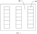
- FIG. 1 is a layout diagram of storage devices in an equipment room. Referring to FIG. 1
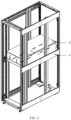
- FIG. 2 is a schematic diagram of a structure of a storage device 100 according to an embodiment of this application.
- the storage device 100 includes a cabinet 1 and a chassis 2 installed in the cabinet 1, and electronic components are installed in the chassis 2 to implement a function of the storage device 100.
- the cabinet 1 may provide protection for the chassis 2 and the storage device 100 in the chassis 2.
- the storage device 100 may not include the cabinet 1. This is not limited in the present invention.
- FIG. 3 is a schematic diagram of a partial structure of a chassis according to an embodiment of this application.
- the chassis 2 includes a chassis body 21 and an installation frame 22 located in the chassis body 21.
- a top cover plate is omitted in the chassis body 21 of the chassis 2 in FIG. 3 .
- the installation frame 22 includes first accommodation space 221 and second accommodation space 222.
- the first accommodation space 221 and the second accommodation space 222 may be used to accommodate hard disks or other electronic components.
- the installation frame 22 may be disposed in the chassis body 21 in a bi-directional pulling manner.
- FIG. 4 is a schematic diagram of a structure of a chassis body according to an embodiment of this application.
- the chassis body 21 has a channel that passes through a first end 211 and a second end 212 of the chassis body 21, and the installation frame 22 is slidably installed in the channel.
- FIG. 5 is a schematic diagram of a status of a chassis according to an embodiment of this application.
- FIG. 6 is a schematic diagram of another status of a chassis according to an embodiment of this application. As shown in FIG. 5 and FIG. 6 , a first part that is of an installation frame 22 and that is close to a first end 211 can slide out from the first end 211 of a chassis body 21, as shown in FIG. 5 .
- a second part that is of the installation frame 22 and that is close to a second end 212 can slide out from the second end 212 of the chassis body 21, as shown in FIG. 6 .
- An example in which the chassis 2 is in a used state is used. It is considered that a front end of the chassis body 21 is the first end 211, and a rear end of the chassis body 21 is the second end 212.
- the installation frame 22 may pull out the first part from the front end of the chassis body 21, and may pull out the second part from the rear end of the chassis body 21. Therefore, components such as hard disks that are in the first part and the second part of the installation frame 22 may be respectively maintained.
- a pull-out length of the installation frame 22 can be effectively reduced by using the foregoing arrangement manner.
- a length of the first part is L1 and a length of the second part is L2
- a total length of the installation frame is L3, where both L1 and L2 are less than L3.
- a maximum pull-out length of the installation frame 22 may be not greater than any one of L1 and L2, and is less than L3. Therefore, after the installation frame 22 is pulled out, a relatively large torque is not generated for a pulling structure between the installation frame 22 and the chassis body 21. This helps reduce manufacturing or purchase costs of the pulling structure and improve market competitiveness of the chassis body 21. In this way, more electronic components can be installed in the installation frame.
- the maximum pull-out length of the installation frame 22 is effectively shortened, when a plurality of chassis bodies 21 are placed in an application site, for example, an equipment room, in a centralized manner, a distance between two chassis bodies 21 that are placed oppositely (for example, front ends or rear ends of the two chassis bodies 21 are placed oppositely) can be effectively shortened. In this way, space utilization of the application site, for example, the equipment room, is increased, and an operation space of an operator is improved.
- the electronic component in this embodiment of the present invention may be hardware, a computing blade, or the like. This is not limited in this embodiment of the present invention.
- the foregoing length is a length in a direction from the first end 211 of the chassis 2 to the second end 212, namely, a length in a stretching direction of the installation frame 22.
- Orientation words such as "front”, “rear”, “left”, “right”, and “bottom” that appear in the embodiments of this application are merely used to describe a relative relationship between directions by using an example in which the chassis 2 and the storage device each are in one used state.
- FIG. 7 is a schematic diagram of a structure of a chassis body according to an embodiment of this application.
- FIG. 8 is a schematic diagram of a structure of an installation frame according to an embodiment of this application.
- the sliding assembly 23 may include a first sliding rail 231 and a second sliding rail 232 that are slidably assembled, the first sliding rail 231 is fastened to the chassis body 21, and the second sliding rail 232 is fastened to the installation frame 22, to implement slidable installation between the installation frame 22 and the chassis body 21.
- the sliding assembly 23 further includes a first limiting assembly 24.
- the first limiting assembly 24 includes a first clamping part and a second clamping part that fit with each other, that is, the first clamping part can be clamped with the second clamping part.
- the first limiting assembly 24 further includes a first drive component that drives the first clamping part to be clamped with the second clamping part, and a second drive component that drives the first clamping part to be detached from the second clamping part.
- the first clamping part is located on the first sliding rail 231
- the second clamping part is located on the second sliding rail 232.
- the first drive component can drive the first clamping part to be clamped with the second clamping part, to limit, in a first direction X, the first sliding rail 231 and the second sliding rail 232 to be fastened relative to each other, that is, to enable the installation frame 22 to be reliably located in the chassis body 21 without easily sliding out of the chassis body 21, thereby improving reliability of the chassis.
- the second drive component is used to drive the first clamping part to be detached from the second clamping part, to enable the installation frame 22 to slide out of the chassis body 21.
- the first direction X is a sliding direction of the sliding assembly 23
- a second direction Y is a direction parallel to a direction in which the first sliding rail 231 faces the second sliding rail 232
- a third direction Z is perpendicular to both the first direction X and the second direction Y.
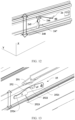
- FIG. 9 is a schematic diagram of a status of a first limiting assembly when an installation frame is fastened to a chassis body according to an embodiment of this application.
- FIG. 10 is a schematic diagram of a status of a first limiting assembly when an installation frame slides out from a first end of a chassis body according to an embodiment of this application.
- FIG. 11 is a schematic diagram of a status of a first limiting assembly when an installation frame slides out from a second end of a chassis body according to an embodiment of this application.
- the first limiting assembly 24 may include a fastening member 241 disposed on the first sliding rail 231 through fastening and a rotating member 242 rotatably disposed on the second sliding rail 232, the rotating member 242 is rotatably connected to the second sliding rail 232 by using a rotating shaft 2423, and the rotating shaft 2423 extends in the second direction Y.
- the rotating member 242 includes a limiting part 2421 and a drive part 2422, the limiting part 2421 fits with the fastening member 241 through clamping, and the drive part 2422 cooperates with the second drive component to drive the rotating member 242 to rotate.
- the reset member When the reset member is specifically disposed, the reset member may be a rotary spring.
- the rotary spring can provide a reset torsion force for rotating of the rotating member, and occupies relatively small installation space.
- a width of the second sliding rail 232 in the third direction Z may be enabled to be less than a width of the first sliding rail 231 in the third direction Z.
- the sliding slot 247 is a gap of the second sliding rail 232.
- the clamping post serves as the second clamping part
- the sliding slot serves as the first clamping part, that is, the clamping post and the reset component are disposed on the second sliding rail
- the sliding slot, the poke lever, and the sliding track are disposed on the first sliding rail.
- a structure of the first limiting assembly in this embodiment is the same as that in the foregoing embodiment, and a difference lies only in an opposite specific setting direction of the first limiting assembly in the first sliding rail and the second sliding rail.
- the chassis further includes two second limiting assemblies 25.
- the two second limiting assemblies 25 are respectively configured to perform limiting when the installation frame 22 slides out from the first end 211 and the second end 212 of the chassis body 21. Specifically, when the first part of the installation frame 22 slides out from the first end 211 of the chassis body 21, a first second limiting assembly 25 enables the installation frame 22 to be fastened relative to the chassis body 21; and when the second part of the installation frame 22 slides out from the second end 212 of the chassis body 21, a second second limiting assembly enables the installation frame 22 to be fastened relative to the chassis body 21.
- the second limiting assembly 25 may include a third clamping part and a fourth clamping part that fit with each other, where the third clamping part can be clamped with the fourth clamping part; and may further include a third drive component that drives the third clamping part to be clamped with the fourth clamping part, and a fourth drive component that drives the third clamping part to be detached from the fourth clamping part.
- the third clamping part is located on the first sliding rail 231, and the fourth clamping part is located on the second sliding rail 232.
- a third drive component of a second limiting assembly 25 located in a sliding direction of the installation frame 22 drives a third clamping part to be clamped with a fourth clamping part, and the installation frame 22 is kept fastened relative to the chassis body 21, to facilitate installation, disassembly, and maintenance of a structure in the installation frame 22; and when the installation frame 22 needs to be retracted into the chassis body 21, a fourth drive component drives the third clamping part to be detached from the four clamping part, so that the installation frame 22 can be retracted into the chassis body 21.
- FIG. 13 is a schematic diagram of a structure of a second limiting assembly according to an embodiment of this application.
- the second limiting assembly 25 When the second limiting assembly 25 is specifically disposed, the second limiting assembly 25 includes a limiting protrusion 251 fastened to the first sliding rail 231, and a wrench 252 installed on the second sliding rail 232 by using a rotating shaft 2521, and the rotating shaft 2521 extends in the second direction Y.
- the wrench 252 has a limiting slot 2522 that fits with the limiting protrusion 251, a reset structure 2523, and an operation part 2524.
- the reset structure 2523 enables the limiting slot 2522 of the wrench 252 to have an elastic force for rotating in a direction toward the limiting protrusion 251, so that when the limiting protrusion 251 is opposite to the limiting slot 2522, the wrench 252 rotates in a direction in which the limiting slot 2522 approaches the limiting protrusion 251, to clamp the limiting protrusion 251 with the limiting slot 2522.
- a user trips the operation part 2524, to enable the wrench 252 to have a driving force in a direction in which the limiting slot 2522 gets away from the limiting protrusion 251, so that the wrench 252 rotates in the direction in which the limiting slot 2522 gets away from the limiting protrusion 251, to detach the limiting slot 2522 from the limiting protrusion 251.
- the limiting protrusion 251 serves as the third clamping part
- the limiting slot 2522 serves as the fourth clamping part
- the reset structure 2523 serves as the third drive component
- the operation part 2524 serves as the fourth drive component.
- the computing blade in this embodiment of the present invention may alternatively be a processor. This is not limited in this embodiment of the present invention.
- the front end and the rear end in the embodiments of the present invention are used as relative concepts, and are not limited to being used as the front end and the rear end in actual product use, but represent the two ends of the channel that passes through the chassis.
Landscapes
- Engineering & Computer Science (AREA)
- Theoretical Computer Science (AREA)
- General Engineering & Computer Science (AREA)
- Computer Hardware Design (AREA)
- Human Computer Interaction (AREA)
- Physics & Mathematics (AREA)
- General Physics & Mathematics (AREA)
- Power Engineering (AREA)
- Microelectronics & Electronic Packaging (AREA)
- Casings For Electric Apparatus (AREA)
- Drawers Of Furniture (AREA)
Claims (6)
- Gehäuse (2), das umfasst:einen Gehäusekörper (21), der einen Kanal (200), der über ein entgegengesetztes erstes Ende und zweites Ende des Gehäusekörpers (21) entlang einer ersten Richtung (X) verläuft, aufweist;einen Installationsrahmen (22), der in dem Kanal (200) des Gehäusekörpers (21) entlang der ersten Richtung (X) verschiebbar eingerichtet ist, wobei ein erster Teil des Installationsrahmens (22) in der Lage ist, aus dem ersten Ende des Gehäusekörpers (21) herauszugleiten, und ein zweiter Teil des Installationsrahmens (22) in der Lage ist, aus dem zweiten Ende des Gehäusekörpers (21) herauszugleiten; undeine Gleitanordnung (23), die eine erste Gleitschiene (231), eine zweite Gleitschiene (232) und eine erste Begrenzungsanordnung (24) umfasst, wobei die erste Gleitschiene (231) an dem Gehäusekörper (21) befestigt ist, die zweite Gleitschiene (232) an dem Installationsrahmen (22) befestigt ist und die erste Gleitschiene (231) und die zweite Gleitschiene (232) verschiebbar angeordnet sind;wobei die erste Begrenzungsanordnung (24) ein erstes Klemmteil und ein zweites Klemmteil, die konfiguriert sind, um zueinander zu passen, eine erste Antriebskomponente, die konfiguriert ist, um das erste Klemmteil und das zweite Klemmteil anzutreiben, um miteinander verklemmt zu sein, und eine zweite Antriebskomponente, die konfiguriert ist, um das erste Klemmteil und das zweite Klemmteil anzutreiben, um voneinander gelöst zu sein, umfasst,wobei:das erste Klemmteil auf der ersten Gleitschiene (231) eingerichtet ist und das zweite Klemmteil auf der zweiten Gleitschiene (232) eingerichtet ist,die erste Antriebskomponente konfiguriert ist, um das erste Klemmteil und das zweite Klemmteil anzutreiben, um miteinander verklemmt zu sein, um den Installationsrahmen (22) an dem Gehäusekörper (21) in der ersten Richtung zu befestigen; die zweite Antriebskomponente konfiguriert ist, um das erste Klemmteil und das zweite Klemmteil anzutreiben, um voneinander gelöst zu sein, um den Installationsrahmen (22) zu aktivieren, aus dem Gehäusekörper (21) herauszugleiten,dadurch gekennzeichnet, dass:das erste Klemmteil ein Befestigungselement (241) ist, das an der ersten Gleitschiene (231) befestigt ist;das zweite Klemmteil ein Drehelement (242) ist, das mit der zweiten Gleitschiene (232) über eine Drehwelle (2423) verbunden ist, wobei das Drehelement (242) ein Antriebsteil (2422) und ein Begrenzungsteil (2421), die konfiguriert sind, um über das Klemmen mit dem Befestigungselement (241) zusammenpassen, umfasst;die erste Antriebskomponente ein Rückstellelement (244) ist, das mit dem Drehelement (242) verbunden ist und konfiguriert ist, um das Drehelement (242) anzutreiben, um sich in eine Richtung, in der das Begrenzungsteil (2421) dem Befestigungselement (241) zugewandt ist, zu drehen, zum Verklemmen des Begrenzungsteils (2421) mit dem Befestigungselement (241); unddie zweite Antriebskomponente ein Zughebel (243) ist, der in der zweiten Gleitschiene (232) verschiebbar angeordnet ist, wobei der Zughebel (243) eine abgestufte geneigte Oberfläche auf einer Seite davon, die dem Drehelement (242) zugewandt ist, aufweist, die konfiguriert ist, um, wenn der Zughebel in die erste Richtung gleitet, gegen das Antriebsteil (2422) anzuliegen und das Drehelement (242) antreiben, um sich in eine Richtung, in der sich das Begrenzungsteil (2421) von dem Befestigungselement (241) entfernt, zu drehen; oderdas zweite Klemmteil ein Befestigungselement (241) ist, das an der zweiten Gleitschiene (232) befestigt ist;das erste Klemmteil ein Drehelement (242) ist, das mit der ersten Gleitschiene (231) über eine Drehwelle (2423) verbunden ist, wobei das Drehelement (242) ein Antriebsteil (2422) und ein Begrenzungsteil (2421) umfasst und konfiguriert ist, um über das Klemmen mit dem Befestigungselement (241) zusammenpassen;die erste Antriebskomponente ein Rückstellelement (244) ist, das mit dem Drehelement (242) verbunden ist und konfiguriert ist, um das Drehelement (242) anzutreiben, um sich in eine Richtung, in der das Begrenzungsteil (2421) dem Befestigungselement (241) zugewandt ist, zu drehen; und die zweite Antriebskomponente ein Zughebel (243) ist, der in der ersten Gleitschiene (231) verschiebbar angeordnet ist, der eine abgestufte geneigte Oberfläche auf einer Seite davon, die dem Drehelement (242) zugewandt ist, aufweist, wobei das Antriebsteil konfiguriert ist, um gegen die abgestufte geneigte Oberfläche anzuliegen, und wenn der Zughebel in die erste Richtung gleitet, die abgestufte geneigte Oberfläche konfiguriert ist, um das Drehelement (242) anzutreiben, um sich in eine Richtung, in der sich das Begrenzungsteil (2421) von dem Befestigungselement (241) entfernt, zu drehen.
- Gehäuse nach Anspruch 1, wobei das Befestigungselement (241) ein Vorsprung ist und das Begrenzungsteil (2421) ein Klemmschlitz ist; oder das Befestigungselement (241) ein Klemmschlitz ist und das Begrenzungsteil (2421) ein Vorsprung ist.
- Gehäuse (2), das umfasst:einen Gehäusekörper (21), der einen Kanal (200), der über ein entgegengesetztes erstes Ende und zweites Ende des Gehäusekörpers (21) entlang einer ersten Richtung (X) verläuft, aufweist;einen Installationsrahmen (22), der in dem Kanal (200) des Gehäusekörpers (21) entlang der ersten Richtung verschiebbar eingerichtet ist, wobei ein erster Teil des Installationsrahmens (22) in der Lage ist, aus dem ersten Ende des Gehäusekörpers (21) herauszugleiten, und ein zweiter Teil des Installationsrahmens (22) in der Lage ist, aus dem zweiten Ende des Gehäusekörpers (21) herauszugleiten; undeine Gleitanordnung (23), die eine erste Gleitschiene (231), eine zweite Gleitschiene (232), die der ersten Gleitschiene (231) entlang einer zweiten Richtung (Y) senkrecht zu der ersten Richtung (X) zugewandt ist, und eine erste Begrenzungsanordnung (24) umfasst, wobei die erste Gleitschiene (231) an dem Gehäusekörper (21) befestigt ist, die zweite Gleitschiene (232) an dem Installationsrahmen (22) befestigt ist und die erste Gleitschiene (231) und die zweite Gleitschiene (232) verschiebbar angeordnet sind;wobei die erste Begrenzungsanordnung (24) ein erstes Klemmteil und ein zweites Klemmteil, die konfiguriert sind, um zueinander zu passen, eine erste Antriebskomponente, die konfiguriert ist, um das erste Klemmteil und das zweite Klemmteil anzutreiben, um miteinander verklemmt zu sein, und eine zweite Antriebskomponente, die konfiguriert ist, um das erste Klemmteil und das zweite Klemmteil anzutreiben, um voneinander gelöst zu sein, umfasst; unddas erste Klemmteil auf der ersten Gleitschiene (231) eingerichtet ist und das zweite Klemmteil auf der zweiten Gleitschiene (232) eingerichtet ist, wobei die erste Antriebskomponente konfiguriert ist, um das erste Klemmteil und das zweite Klemmteil anzutreiben, um miteinander verklemmt zu sein, um den Installationsrahmen (22) an dem Gehäusekörper (21) in der ersten Richtung zu befestigen, und die zweite Antriebskomponente konfiguriert ist, um das erste Klemmteil und das zweite Klemmteil anzutreiben, um voneinander gelöst zu sein, um den Installationsrahmen (22) zu aktivieren, um aus dem Gehäusekörper (21) herauszugleiten, dadurch gekennzeichnet, dass:die zweite Gleitschiene (232) eine Gleitbahn (248), die sich in die erste Richtung (X) erstreckt, einschließt;das erste Klemmteil ein Klemmpfosten (245) ist, der auf der ersten Gleitschiene (231) eingerichtet ist, wobei der Klemmpfosten angepasst ist, um sich auf der ersten Schiene (231) entlang einer dritten Richtung (Z), die sowohl senkrecht zu der ersten Richtung (X) als auch zu der zweiten Richtung (Y) ist, zu bewegen;das zweite Klemmteil ein Gleitschlitz (247) ist, der auf der zweiten Gleitschiene (232) entlang der dritten Richtung (Z) eingerichtet ist, wobei der Gleitschlitz (247) an einem unteren Ende davon mit der Gleitbahn (248) verbunden ist und konfiguriert ist, um dem Klemmpfosten (245) zu entsprechen, wenn sich der Installationsrahmen (22) vollständig in dem Gehäusekörper (21) befindet;die erste Antriebskomponente eine Rückstellkomponente ist, die mit dem Klemmpfosten (245) verbunden ist und konfiguriert ist, um den Klemmpfosten (245) anzutreiben, um sich zu dem Unterteil des Gleitschlitzes (247) hin zu bewegen, um in den Gleitschlitz (247) zu gleiten, wenn sich der Installationsrahmen (22) vollständig in dem Gehäusekörper (21) befindet, um den Installationsrahmen (22) mit dem Gehäusekörper (21) in der Gleitrichtung (X) der Gleitanordnung (23) zu begrenzen;die zweite Antriebskomponente ein Stoßhebel (246) ist, der auf der zweiten Gleitschiene (232) eingerichtet ist, wobei, wenn sich der Klemmpfosten (245) in dem Gleitschlitz (247) befindet, der Stoßhebel (246) angepasst ist, um den Klemmpfosten (245) zu überlappen, um den Klemmpfosten (245) zu drücken, um sich in eine Richtung, in der der Klemmpfosten (245) von dem Gleitschlitz (247) gelöst ist und in die Gleitschiene (248) gleitet, zu bewegen, um den Installationsrahmen (22) zu aktivieren, um aus dem Gehäusekörper (21) herauszugleiten;
oderdie erste Gleitschiene (231) eine Gleitbahn (248), die sich in die erste Richtung erstreckt, einschließt;das zweite Klemmteil ein Klemmpfosten (245) ist, der auf der zweiten Gleitschiene (232) eingerichtet ist, wobei der Klemmpfosten angepasst ist, um sich auf der ersten Schiene (231) entlang einer dritten Richtung (Z) senkrecht zu der ersten Richtung (X) zu bewegen;das erste Klemmteil ein Gleitschlitz (247) ist, der auf der ersten Gleitschiene (231) entlang der dritten Richtung (Z) senkrecht zu der ersten Richtung (X) eingerichtet ist,wobei der Gleitschlitz (247) an einem unteren Ende davon mit der Gleitbahn (248) verbunden ist und konfiguriert ist, um dem Klemmpfosten (245) zu entsprechen, wenn sich der Installationsrahmen (22) vollständig in dem Gehäusekörper (21) befindet;die erste Antriebskomponente eine Rückstellkomponente ist, die mit dem Klemmpfosten (245) verbunden ist und konfiguriert ist, um den Klemmpfosten (245) anzutreiben, um sich zu dem Boden des Gleitschlitzes (247) hin zu bewegen, und um in den Gleitschlitz (247) zu gleiten, wenn sich der Installationsrahmen (22) vollständig in dem Gehäusekörper (21) befindet, um den Installationsrahmen (22) mit dem Gehäusekörper (21) in der Gleitrichtung (X) der Gleitanordnung (23) zu begrenzen;die zweite Antriebskomponente ein Stoßhebel (246) ist, der auf der ersten Gleitschiene (231) eingerichtet ist, wobei, wenn sich der Klemmpfosten (245) in dem Gleitschlitz (247) befindet, der Stoßhebel (246) angepasst ist, um den Klemmpfosten (245) zu überlappen, um den Klemmpfosten (245) zu drücken, um sich in eine Richtung, in der der Klemmpfosten (245) von dem Gleitschlitz (247) gelöst ist und in die Gleitschiene (248) gleitet, zu bewegen, um den Installationsrahmen (22) zu aktivieren, um aus dem Gehäusekörper (21) herauszugleiten. - Gehäuse (2) nach einem der Ansprüche 1 bis 3, das ferner zwei zweiteBegrenzungsanordnungen (25), die jeweils konfiguriert sind, um den Installationsrahmen (22) an dem Gehäusekörper (21) zu befestigen, nachdem der erste Teil beziehungsweise der zweite Teil des Installationsrahmens (22) um eine bestimmte Distanz aus dem ersten Ende (211) beziehungsweise dem zweiten Ende (212) des Gehäusekörpers (21) herausgleitet, umfasst, wobeijede zweite Begrenzungsanordnung (25) ein drittes Klemmteil, ein viertes Klemmteil, eine dritte Antriebskomponente, die konfiguriert ist, um das dritte Klemmteil anzutreiben, um mit dem vierten Klemmteil verklemmt zu sein, um den Installationsrahmen (22) an dem Gehäusekörper (21) in der ersten Richtung zu befestigen, und eine vierte Antriebskomponente, die konfiguriert ist, um das dritte Klemmteil anzutreiben, um von dem vierten Klemmteil gelöst zu sein, um den Installationsrahmen (22) zu aktivieren, um in den Gehäusekörper (21) hineinzugleiten, umfasst, wobei sich das dritte Klemmteil auf der ersten Gleitschiene (231) befindet und sich das vierte Klemmteil auf der zweiten Gleitschiene (232) befindet.
- Speichervorrichtung, die das Gehäuse nach einem der Ansprüche 1 bis 4 umfasst.
- Speichervorrichtung nach Anspruch 5, wobei eine Festplatte in einem Installationsrahmen des Gehäuses installiert ist.
Applications Claiming Priority (2)
| Application Number | Priority Date | Filing Date | Title |
|---|---|---|---|
| CN202010460909.0A CN113741638B (zh) | 2020-05-27 | 2020-05-27 | 一种机箱和存储设备 |
| PCT/CN2021/094895 WO2021238765A1 (zh) | 2020-05-27 | 2021-05-20 | 一种机箱和存储设备 |
Publications (3)
| Publication Number | Publication Date |
|---|---|
| EP4134786A1 EP4134786A1 (de) | 2023-02-15 |
| EP4134786A4 EP4134786A4 (de) | 2023-10-25 |
| EP4134786B1 true EP4134786B1 (de) | 2025-07-09 |
Family
ID=78723740
Family Applications (1)
| Application Number | Title | Priority Date | Filing Date |
|---|---|---|---|
| EP21812991.4A Active EP4134786B1 (de) | 2020-05-27 | 2021-05-20 | Etui und aufbewahrungsvorrichtung |
Country Status (4)
| Country | Link |
|---|---|
| US (1) | US12289855B2 (de) |
| EP (1) | EP4134786B1 (de) |
| CN (1) | CN113741638B (de) |
| WO (1) | WO2021238765A1 (de) |
Families Citing this family (1)
| Publication number | Priority date | Publication date | Assignee | Title |
|---|---|---|---|---|
| CN115091783B (zh) * | 2022-07-25 | 2022-11-11 | 苏州丹卡精密机械有限公司 | 一种复合材料网络设备机箱生产用快速成型装置 |
Family Cites Families (12)
| Publication number | Priority date | Publication date | Assignee | Title |
|---|---|---|---|---|
| CN101194789B (zh) * | 2006-12-08 | 2012-11-21 | 鸿富锦精密工业(深圳)有限公司 | 滑轨装置 |
| CN101332022B (zh) * | 2007-06-27 | 2010-11-10 | 鸿富锦精密工业(深圳)有限公司 | 滑轨装置 |
| TWI524838B (zh) * | 2013-11-06 | 2016-03-01 | 營邦企業股份有限公司 | 工業電腦機櫃及其雙向滑軌結構 |
| CN104640407A (zh) * | 2013-11-11 | 2015-05-20 | 营邦企业股份有限公司 | 工业计算机机柜及其双向滑轨结构 |
| CN104375596A (zh) * | 2014-11-24 | 2015-02-25 | 英业达科技有限公司 | 服务器机箱 |
| TWI548367B (zh) * | 2015-08-31 | 2016-09-11 | King Slide Works Co Ltd | 滑軌總成 |
| CN206115362U (zh) * | 2016-06-28 | 2017-04-19 | 华为技术有限公司 | 一种机箱及服务器 |
| CN108628411B (zh) * | 2017-03-23 | 2019-09-20 | 鸿富锦精密电子(天津)有限公司 | 机箱 |
| CN206975580U (zh) * | 2017-06-27 | 2018-02-06 | 美超微电脑股份有限公司 | 硬盘固持机构及使用该机构的服务器 |
| CN109002096B (zh) * | 2018-07-17 | 2020-10-16 | 新华三信息技术有限公司 | 一种机箱组件和服务器 |
| CN210155586U (zh) * | 2019-06-14 | 2020-03-17 | 昆山研祥智能科技有限公司 | 抽拉装置及其组件 |
| CN110708914B (zh) * | 2019-08-30 | 2021-06-01 | 华为技术有限公司 | 卡扣组件、板卡以及电子设备 |
-
2020
- 2020-05-27 CN CN202010460909.0A patent/CN113741638B/zh active Active
-
2021
- 2021-05-20 WO PCT/CN2021/094895 patent/WO2021238765A1/zh not_active Ceased
- 2021-05-20 EP EP21812991.4A patent/EP4134786B1/de active Active
-
2022
- 2022-11-15 US US17/987,103 patent/US12289855B2/en active Active
Also Published As
| Publication number | Publication date |
|---|---|
| US20230066108A1 (en) | 2023-03-02 |
| CN113741638A (zh) | 2021-12-03 |
| EP4134786A1 (de) | 2023-02-15 |
| WO2021238765A1 (zh) | 2021-12-02 |
| EP4134786A4 (de) | 2023-10-25 |
| CN113741638B (zh) | 2024-03-01 |
| US12289855B2 (en) | 2025-04-29 |
Similar Documents
| Publication | Publication Date | Title |
|---|---|---|
| US8018724B2 (en) | Server cabinet and computer server system using same | |
| US9412418B2 (en) | In-box quick release access device structure | |
| US7088580B2 (en) | Mounting apparatus for data storage device | |
| CN101908363A (zh) | 磁碟机抽取结构 | |
| US12289855B2 (en) | Chassis and storage device | |
| EP4075235B1 (de) | Schrank und aufbewahrungsvorrichtung | |
| US7057890B2 (en) | Drawer for digital data storage device | |
| TW201220023A (en) | Server rack structure | |
| US20060164802A1 (en) | Portable computer enclosure | |
| US20080090511A1 (en) | Mounting apparatus for fan | |
| CN204155193U (zh) | 储存媒体转接结构及使用该结构的服务器 | |
| CN101739088A (zh) | 电脑主机 | |
| US12560986B2 (en) | Chassis-based storage device with dual-end sliding frame | |
| CN202711141U (zh) | 机箱内存取装置的快拆结构 | |
| US8545249B2 (en) | Locking assembly and communication apparatus using same | |
| EP3672380B1 (de) | Server-computersystem mit rotierendem träger | |
| CN211128670U (zh) | 抽拉模块阵列 | |
| CN216210835U (zh) | 一种带自锁功能的服务器机箱 | |
| US8081452B2 (en) | Computer case | |
| CN111090309B (zh) | 一种服务器及其高通风率低流阻硬盘托架 | |
| TWI875079B (zh) | 硬碟固定裝置及主機殼 | |
| US8764132B2 (en) | Enclosure having detachable panel assembly | |
| CN211019110U (zh) | 一种信息技术工程用配线架 | |
| CN221101350U (zh) | 一种工控机箱排线结构 | |
| CN219392579U (zh) | 电子设备 |
Legal Events
| Date | Code | Title | Description |
|---|---|---|---|
| STAA | Information on the status of an ep patent application or granted ep patent |
Free format text: STATUS: THE INTERNATIONAL PUBLICATION HAS BEEN MADE |
|
| PUAI | Public reference made under article 153(3) epc to a published international application that has entered the european phase |
Free format text: ORIGINAL CODE: 0009012 |
|
| STAA | Information on the status of an ep patent application or granted ep patent |
Free format text: STATUS: REQUEST FOR EXAMINATION WAS MADE |
|
| 17P | Request for examination filed |
Effective date: 20221110 |
|
| AK | Designated contracting states |
Kind code of ref document: A1 Designated state(s): AL AT BE BG CH CY CZ DE DK EE ES FI FR GB GR HR HU IE IS IT LI LT LU LV MC MK MT NL NO PL PT RO RS SE SI SK SM TR |
|
| DAV | Request for validation of the european patent (deleted) | ||
| DAX | Request for extension of the european patent (deleted) | ||
| A4 | Supplementary search report drawn up and despatched |
Effective date: 20230925 |
|
| RIC1 | Information provided on ipc code assigned before grant |
Ipc: G11B 33/12 20060101ALI20230919BHEP Ipc: H05K 7/14 20060101ALI20230919BHEP Ipc: H05K 7/18 20060101ALI20230919BHEP Ipc: G06F 1/18 20060101AFI20230919BHEP |
|
| STAA | Information on the status of an ep patent application or granted ep patent |
Free format text: STATUS: EXAMINATION IS IN PROGRESS |
|
| 17Q | First examination report despatched |
Effective date: 20240620 |
|
| 17Q | First examination report despatched |
Effective date: 20240626 |
|
| GRAP | Despatch of communication of intention to grant a patent |
Free format text: ORIGINAL CODE: EPIDOSNIGR1 |
|
| STAA | Information on the status of an ep patent application or granted ep patent |
Free format text: STATUS: GRANT OF PATENT IS INTENDED |
|
| INTG | Intention to grant announced |
Effective date: 20250115 |
|
| GRAS | Grant fee paid |
Free format text: ORIGINAL CODE: EPIDOSNIGR3 |
|
| GRAA | (expected) grant |
Free format text: ORIGINAL CODE: 0009210 |
|
| STAA | Information on the status of an ep patent application or granted ep patent |
Free format text: STATUS: THE PATENT HAS BEEN GRANTED |
|
| AK | Designated contracting states |
Kind code of ref document: B1 Designated state(s): AL AT BE BG CH CY CZ DE DK EE ES FI FR GB GR HR HU IE IS IT LI LT LU LV MC MK MT NL NO PL PT RO RS SE SI SK SM TR |
|
| REG | Reference to a national code |
Ref country code: GB Ref legal event code: FG4D |
|
| REG | Reference to a national code |
Ref country code: CH Ref legal event code: EP |
|
| REG | Reference to a national code |
Ref country code: IE Ref legal event code: FG4D |
|
| REG | Reference to a national code |
Ref country code: DE Ref legal event code: R096 Ref document number: 602021033905 Country of ref document: DE |
|
| REG | Reference to a national code |
Ref country code: NL Ref legal event code: MP Effective date: 20250709 |
|
| PG25 | Lapsed in a contracting state [announced via postgrant information from national office to epo] |
Ref country code: PT Free format text: LAPSE BECAUSE OF FAILURE TO SUBMIT A TRANSLATION OF THE DESCRIPTION OR TO PAY THE FEE WITHIN THE PRESCRIBED TIME-LIMIT Effective date: 20251110 |
|
| PG25 | Lapsed in a contracting state [announced via postgrant information from national office to epo] |
Ref country code: NL Free format text: LAPSE BECAUSE OF FAILURE TO SUBMIT A TRANSLATION OF THE DESCRIPTION OR TO PAY THE FEE WITHIN THE PRESCRIBED TIME-LIMIT Effective date: 20250709 |
|
| REG | Reference to a national code |
Ref country code: AT Ref legal event code: MK05 Ref document number: 1812416 Country of ref document: AT Kind code of ref document: T Effective date: 20250709 |
|
| PG25 | Lapsed in a contracting state [announced via postgrant information from national office to epo] |
Ref country code: IS Free format text: LAPSE BECAUSE OF FAILURE TO SUBMIT A TRANSLATION OF THE DESCRIPTION OR TO PAY THE FEE WITHIN THE PRESCRIBED TIME-LIMIT Effective date: 20251109 |
|
| PG25 | Lapsed in a contracting state [announced via postgrant information from national office to epo] |
Ref country code: NO Free format text: LAPSE BECAUSE OF FAILURE TO SUBMIT A TRANSLATION OF THE DESCRIPTION OR TO PAY THE FEE WITHIN THE PRESCRIBED TIME-LIMIT Effective date: 20251009 |
|
| REG | Reference to a national code |
Ref country code: LT Ref legal event code: MG9D |
|
| PG25 | Lapsed in a contracting state [announced via postgrant information from national office to epo] |
Ref country code: AT Free format text: LAPSE BECAUSE OF FAILURE TO SUBMIT A TRANSLATION OF THE DESCRIPTION OR TO PAY THE FEE WITHIN THE PRESCRIBED TIME-LIMIT Effective date: 20250709 |
|
| PG25 | Lapsed in a contracting state [announced via postgrant information from national office to epo] |
Ref country code: FI Free format text: LAPSE BECAUSE OF FAILURE TO SUBMIT A TRANSLATION OF THE DESCRIPTION OR TO PAY THE FEE WITHIN THE PRESCRIBED TIME-LIMIT Effective date: 20250709 |
|
| PG25 | Lapsed in a contracting state [announced via postgrant information from national office to epo] |
Ref country code: HR Free format text: LAPSE BECAUSE OF FAILURE TO SUBMIT A TRANSLATION OF THE DESCRIPTION OR TO PAY THE FEE WITHIN THE PRESCRIBED TIME-LIMIT Effective date: 20250709 |
|
| PG25 | Lapsed in a contracting state [announced via postgrant information from national office to epo] |
Ref country code: GR Free format text: LAPSE BECAUSE OF FAILURE TO SUBMIT A TRANSLATION OF THE DESCRIPTION OR TO PAY THE FEE WITHIN THE PRESCRIBED TIME-LIMIT Effective date: 20251010 |
|
| PG25 | Lapsed in a contracting state [announced via postgrant information from national office to epo] |
Ref country code: SE Free format text: LAPSE BECAUSE OF FAILURE TO SUBMIT A TRANSLATION OF THE DESCRIPTION OR TO PAY THE FEE WITHIN THE PRESCRIBED TIME-LIMIT Effective date: 20250709 |
|
| PG25 | Lapsed in a contracting state [announced via postgrant information from national office to epo] |
Ref country code: LV Free format text: LAPSE BECAUSE OF FAILURE TO SUBMIT A TRANSLATION OF THE DESCRIPTION OR TO PAY THE FEE WITHIN THE PRESCRIBED TIME-LIMIT Effective date: 20250709 |
|
| PG25 | Lapsed in a contracting state [announced via postgrant information from national office to epo] |
Ref country code: BG Free format text: LAPSE BECAUSE OF FAILURE TO SUBMIT A TRANSLATION OF THE DESCRIPTION OR TO PAY THE FEE WITHIN THE PRESCRIBED TIME-LIMIT Effective date: 20250709 Ref country code: PL Free format text: LAPSE BECAUSE OF FAILURE TO SUBMIT A TRANSLATION OF THE DESCRIPTION OR TO PAY THE FEE WITHIN THE PRESCRIBED TIME-LIMIT Effective date: 20250709 |
|
| PG25 | Lapsed in a contracting state [announced via postgrant information from national office to epo] |
Ref country code: RS Free format text: LAPSE BECAUSE OF FAILURE TO SUBMIT A TRANSLATION OF THE DESCRIPTION OR TO PAY THE FEE WITHIN THE PRESCRIBED TIME-LIMIT Effective date: 20251009 |
|
| PG25 | Lapsed in a contracting state [announced via postgrant information from national office to epo] |
Ref country code: ES Free format text: LAPSE BECAUSE OF FAILURE TO SUBMIT A TRANSLATION OF THE DESCRIPTION OR TO PAY THE FEE WITHIN THE PRESCRIBED TIME-LIMIT Effective date: 20250709 |
|
| PG25 | Lapsed in a contracting state [announced via postgrant information from national office to epo] |
Ref country code: SM Free format text: LAPSE BECAUSE OF FAILURE TO SUBMIT A TRANSLATION OF THE DESCRIPTION OR TO PAY THE FEE WITHIN THE PRESCRIBED TIME-LIMIT Effective date: 20250709 |
|
| PGFP | Annual fee paid to national office [announced via postgrant information from national office to epo] |
Ref country code: GB Payment date: 20260325 Year of fee payment: 6 |
|
| PG25 | Lapsed in a contracting state [announced via postgrant information from national office to epo] |
Ref country code: DK Free format text: LAPSE BECAUSE OF FAILURE TO SUBMIT A TRANSLATION OF THE DESCRIPTION OR TO PAY THE FEE WITHIN THE PRESCRIBED TIME-LIMIT Effective date: 20250709 |
|
| PG25 | Lapsed in a contracting state [announced via postgrant information from national office to epo] |
Ref country code: IT Free format text: LAPSE BECAUSE OF FAILURE TO SUBMIT A TRANSLATION OF THE DESCRIPTION OR TO PAY THE FEE WITHIN THE PRESCRIBED TIME-LIMIT Effective date: 20250709 |
|
| PG25 | Lapsed in a contracting state [announced via postgrant information from national office to epo] |
Ref country code: CZ Free format text: LAPSE BECAUSE OF FAILURE TO SUBMIT A TRANSLATION OF THE DESCRIPTION OR TO PAY THE FEE WITHIN THE PRESCRIBED TIME-LIMIT Effective date: 20250709 |
|
| PG25 | Lapsed in a contracting state [announced via postgrant information from national office to epo] |
Ref country code: EE Free format text: LAPSE BECAUSE OF FAILURE TO SUBMIT A TRANSLATION OF THE DESCRIPTION OR TO PAY THE FEE WITHIN THE PRESCRIBED TIME-LIMIT Effective date: 20250709 Ref country code: SK Free format text: LAPSE BECAUSE OF FAILURE TO SUBMIT A TRANSLATION OF THE DESCRIPTION OR TO PAY THE FEE WITHIN THE PRESCRIBED TIME-LIMIT Effective date: 20250709 |