EP4134817A1 - Verfahren und system zur leistungsverwaltung von verteilten softwareanwendungen - Google Patents
Verfahren und system zur leistungsverwaltung von verteilten softwareanwendungen Download PDFInfo
- Publication number
- EP4134817A1 EP4134817A1 EP22188644.3A EP22188644A EP4134817A1 EP 4134817 A1 EP4134817 A1 EP 4134817A1 EP 22188644 A EP22188644 A EP 22188644A EP 4134817 A1 EP4134817 A1 EP 4134817A1
- Authority
- EP
- European Patent Office
- Prior art keywords
- aut
- performance
- workload
- hardware
- transaction
- Prior art date
- Legal status (The legal status is an assumption and is not a legal conclusion. Google has not performed a legal analysis and makes no representation as to the accuracy of the status listed.)
- Granted
Links
Images


Classifications
-
- G—PHYSICS
- G06—COMPUTING OR CALCULATING; COUNTING
- G06F—ELECTRIC DIGITAL DATA PROCESSING
- G06F8/00—Arrangements for software engineering
- G06F8/70—Software maintenance or management
- G06F8/77—Software metrics
-
- G—PHYSICS
- G06—COMPUTING OR CALCULATING; COUNTING
- G06F—ELECTRIC DIGITAL DATA PROCESSING
- G06F11/00—Error detection; Error correction; Monitoring
- G06F11/36—Prevention of errors by analysis, debugging or testing of software
- G06F11/3668—Testing of software
- G06F11/3672—Test management
- G06F11/3688—Test management for test execution, e.g. scheduling of test suites
-
- G—PHYSICS
- G06—COMPUTING OR CALCULATING; COUNTING
- G06F—ELECTRIC DIGITAL DATA PROCESSING
- G06F11/00—Error detection; Error correction; Monitoring
- G06F11/30—Monitoring
- G06F11/3003—Monitoring arrangements specially adapted to the computing system or computing system component being monitored
- G06F11/302—Monitoring arrangements specially adapted to the computing system or computing system component being monitored where the computing system component is a software system
-
- G—PHYSICS
- G06—COMPUTING OR CALCULATING; COUNTING
- G06F—ELECTRIC DIGITAL DATA PROCESSING
- G06F11/00—Error detection; Error correction; Monitoring
- G06F11/30—Monitoring
- G06F11/34—Recording or statistical evaluation of computer activity, e.g. of down time, of input/output operation ; Recording or statistical evaluation of user activity, e.g. usability assessment
- G06F11/3409—Recording or statistical evaluation of computer activity, e.g. of down time, of input/output operation ; Recording or statistical evaluation of user activity, e.g. usability assessment for performance assessment
-
- G—PHYSICS
- G06—COMPUTING OR CALCULATING; COUNTING
- G06F—ELECTRIC DIGITAL DATA PROCESSING
- G06F11/00—Error detection; Error correction; Monitoring
- G06F11/30—Monitoring
- G06F11/34—Recording or statistical evaluation of computer activity, e.g. of down time, of input/output operation ; Recording or statistical evaluation of user activity, e.g. usability assessment
- G06F11/3409—Recording or statistical evaluation of computer activity, e.g. of down time, of input/output operation ; Recording or statistical evaluation of user activity, e.g. usability assessment for performance assessment
- G06F11/3414—Workload generation, e.g. scripts, playback
-
- G—PHYSICS
- G06—COMPUTING OR CALCULATING; COUNTING
- G06F—ELECTRIC DIGITAL DATA PROCESSING
- G06F11/00—Error detection; Error correction; Monitoring
- G06F11/30—Monitoring
- G06F11/34—Recording or statistical evaluation of computer activity, e.g. of down time, of input/output operation ; Recording or statistical evaluation of user activity, e.g. usability assessment
- G06F11/3409—Recording or statistical evaluation of computer activity, e.g. of down time, of input/output operation ; Recording or statistical evaluation of user activity, e.g. usability assessment for performance assessment
- G06F11/3428—Benchmarking
-
- G—PHYSICS
- G06—COMPUTING OR CALCULATING; COUNTING
- G06F—ELECTRIC DIGITAL DATA PROCESSING
- G06F11/00—Error detection; Error correction; Monitoring
- G06F11/30—Monitoring
- G06F11/34—Recording or statistical evaluation of computer activity, e.g. of down time, of input/output operation ; Recording or statistical evaluation of user activity, e.g. usability assessment
- G06F11/3466—Performance evaluation by tracing or monitoring
-
- G—PHYSICS
- G06—COMPUTING OR CALCULATING; COUNTING
- G06F—ELECTRIC DIGITAL DATA PROCESSING
- G06F11/00—Error detection; Error correction; Monitoring
- G06F11/36—Prevention of errors by analysis, debugging or testing of software
- G06F11/3668—Testing of software
- G06F11/3672—Test management
- G06F11/3684—Test management for test design, e.g. generating new test cases
-
- G—PHYSICS
- G06—COMPUTING OR CALCULATING; COUNTING
- G06F—ELECTRIC DIGITAL DATA PROCESSING
- G06F2201/00—Indexing scheme relating to error detection, to error correction, and to monitoring
- G06F2201/81—Threshold
Definitions
- the disclosure herein generally relates to the field of software performance management, and, more particularly, to a method and a system for performance tuning and benchmarking of distributed software applications.
- Performance and scalability of distributed software applications serving critical business needs is of highest priority to ensure customer experience, business throughput and optimal cost of operation.
- ensuring performance scalability requires significant effort and sophisticated set of skills which are not easy to find. This most often leads to a reduced focus on these aspects, which in turn causes subsequent disruptions that are damaging to the business.
- a processor implemented method when used for tuning and benchmarking an Application Under Test (AUT), initially determines a context of the AUT by processing an input data collected for the AUT, via one or more hardware processors. Further, a plurality of test scripts are generated for the AUT, based on the determined context, via the one or more hardware processors, wherein the plurality of test scripts are used to test performance of the AUT under a plurality of load conditions.
- AUT Application Under Test
- a workload is generated based on each of the plurality of test scripts, of each of the plurality of load conditions, via the one or more hardware processors. Further, the generated workload for each of the plurality of load conditions is applied on the AUT, via the one or more hardware processors. Further, it is determined if a measured performance of the AUT after applying the generated workload for each of the plurality of load conditions is matching a pre-defined performance threshold, via the one or more hardware processors, wherein the performance of the AUT is measured based on collected data representing performance behaviour of the AUT. Further, for all load conditions for which the measured performance is below the performance threshold, the AUT is tuned to match the pre-defined performance with the performance threshold, via the one or more hardware processors. Tuning the AUT includes determining an optimal configuration for the one or more of the plurality of load conditions.
- a system in another aspect, includes one or more hardware processors, an I/O interface, and a memory storing a plurality of instructions.
- the plurality of instructions when executed, cause the one or more hardware processors to determine a context of an application under test (AUT) by processing an input data collected for the AUT. Further, the system generates a plurality of test scripts for the AUT, based on the determined context, wherein the plurality of test scripts are used to test performance of the AUT under a plurality of load conditions. Further, the system generates a workload based on each of the plurality of test scripts, of each of the plurality of load conditions. Further, the generated workload for each of the plurality of load conditions is applied on the AUT by the system.
- the system determines if a measured performance of the AUT after applying the generated workload of each of the plurality of load conditions is matching a pre-defined performance threshold, wherein the performance of the AUT is measured based on collected data representing performance behaviour of the AUT. Further, for all load conditions for which the measured performance is below the pre-defined performance threshold, the AUT is tuned to match the performance with the performance threshold. Tuning the AUT includes determining an optimal configuration for the one or more of the plurality of load conditions.
- a non-transitory computer readable medium includes a plurality of instructions, which when executed, cause the following actions.
- the non-transitory computer readable medium when used for tuning and benchmarking an Application Under Test (AUT), initially determines a context of the AUT by processing an input data collected for the AUT, via one or more hardware processors. Further, a plurality of test scripts are generated for the AUT, based on the determined context, via the one or more hardware processors, wherein the plurality of test scripts are used to test performance of the AUT under a plurality of load conditions.
- AUT Application Under Test
- a workload is generated based on each of the plurality of test scripts, for each of the plurality of load conditions, via the one or more hardware processors. Further, the generated workload for each of the plurality of load conditions is applied on the AUT, via the one or more hardware processors. Further, it is determined if a measured performance of the AUT after applying the generated workload of each of the plurality of load conditions is matching a pre-defined performance threshold, via the one or more hardware processors, wherein the performance of the AUT is measured based on collected data representing performance behaviour of the AUT. Further, for all load conditions for which the measured performance is below the pre-defined performance threshold, the AUT is tuned to match the performance with the performance threshold, via the one or more hardware processors. Tuning the AUT includes determining an optimal configuration for the one or more of the plurality of load conditions.
- FIG. 1 through FIG. 7 where similar reference characters denote corresponding features consistently throughout the figures, there are shown preferred embodiments and these embodiments are described in the context of the following exemplary system and/or method.
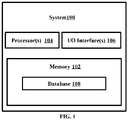
- FIG. 1 illustrates an exemplary system for performance tuning and benchmarking of applications, according to some embodiments of the present disclosure.
- the system 100 includes a processor(s) 104, communication interface device(s), alternatively referred as input/output (I/O) interface(s) 106, and one or more data storage devices or a memory 102 operatively coupled to the processor(s) 104.
- the system 100 with one or more hardware processors is configured to execute functions of one or more functional blocks of the system 100.
- the processor(s) 104 can be one or more hardware processors 104.
- the one or more hardware processors 104 can be implemented as one or more microprocessors, microcomputers, microcontrollers, digital signal processors, central processing units, state machines, logic circuitries, and/or any devices that manipulate signals based on operational instructions.
- the one or more hardware processors 104 are configured to fetch and execute computer-readable instructions stored in the memory 102.
- the system 100 can be implemented in a variety of computing systems including laptop computers, notebooks, hand-held devices such as mobile phones, workstations, mainframe computers, servers, and the like.
- the I/O interface(s) 106 can include a variety of software and hardware interfaces, for example, a web interface, a graphical user interface to display the generated target images and the like and can facilitate multiple communications within a wide variety of networks N/W and protocol types, including wired networks, for example, LAN, cable, etc., and wireless networks, such as WLAN, cellular and the like.
- the I/O interface (s) 106 can include one or more ports for connecting to a number of external devices or to another server or devices.
- the memory 102 may include any computer-readable medium known in the art including, for example, volatile memory, such as static random access memory (SRAM) and dynamic random access memory (DRAM), and/or non-volatile memory, such as read only memory (ROM), erasable programmable ROM, flash memories, hard disks, optical disks, and magnetic tapes.
- volatile memory such as static random access memory (SRAM) and dynamic random access memory (DRAM)
- DRAM dynamic random access memory
- non-volatile memory such as read only memory (ROM), erasable programmable ROM, flash memories, hard disks, optical disks, and magnetic tapes.
- the memory 102 includes a database 108 that stores all data associated with the application performance tuning and benchmarking being performed by the system 100.
- the database 108 stores the configurable instructions that are executed to cause the one or more hardware processors 104 to perform various steps associated with the application performance tuning and benchmarking.
- the database 108 may further store all data that is collected as input for determining the performance of an Application Under Test (AUT).
- the database 108 may further store information on the determined performance of the AUT, and information on corresponding tuning (and values of associated parameters) performed to improve performance of the AUT.
- the database 108 may further store values of different thresholds that are used by the system 100 during the application performance tuning and benchmarking. Functions of the components of the system 100 are explained in conjunction with the flow diagrams in FIG. 2 and FIG. 3 .
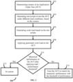
- FIG. 2 is a flow diagram depicting steps involved in the performance tuning and benchmarking being performed by the system of FIG. 1 , according to some embodiments of the present disclosure.
- AUT Application Under Test
- the system 100 To monitor an application (alternately referred to as Application Under Test or AUT), the system 100 establishes connection with the AUT via one or more appropriate communication channels provided by the I/O interface 106.
- FIG. 4 An example structure of the AUT is depicted in FIG. 4 .
- the AUT has different components, wherein each component may be a combination of software and hardware components.
- Each of the components handles a particular work/job/responsibility, and has a particular capacity in terms of amount of work that can be handled by the component.
- the components of the AUT may be communicating each other for data and/or control transfer as part of handling the workload that is given as input to the AUT.
- the components together process the workload and generate the corresponding results, with specific throughput and latency. If any of the components is underperforming, overall performance and throughput of the AUT is adversely affected.
- the performance tuning and benchmarking being performed by the system 100 involves performance assessment at individual component level as well as at the overall system level.
- FIG. 4 also depicts how the system 100 can be connected to the AUT to perform the performance tuning and benchmarking.
- the system 100 collects data on various parameters associated with the AUT, via one or more channels provided by the I/O interface(s) 106 that connect the system 100 with the AUT, and then processes the collected data to identify a context of the AUT.
- the input data may be an image and/or text-based data sources such as architecture diagrams, deployment BOMs and so on, collected for the AUT.
- 'context' may refer to various information on structure and working of the AUT, which may be arranged to a plurality of data models as listed below:
- the system 100 may use the system reference model as input for determining the context of the AUT.
- the system 100 extracts a component architecture, a technology architecture, a service architecture, a deployment architecture, a resource capacity architecture, a transaction flow, performance metrics list, tuneable controls list, and workload transaction specifications of the AUT, from the input data.
- the model inputs may be provided in multiple forms such as but not limited to:
- the extracted values of the various parameters together represent the context of the AUT.
- the system 100 generates a plurality of test scripts to test the AUT under different load conditions.
- the system 100 generates the test scripts based on the technology architecture and the workload transactions specifications from the context of the AUT.
- the system 100 then creates the plurality of test scripts such that the test scripts correspond to the plurality of workload specifications.
- the one or more hardware processors 104 may form a workload designer consisting of record, replay and scripting interfaces.
- the system 100 may version control and store the scripts in a repository in the database 108.
- the test scripts may have scripts and runtime parameters (for with all intended load variations and load conditions) to perform the load tests on the AUT.
- the system 100 may provide suitable interfaces for an authorized user to define different workload scenarios that need to be characterized in the system behavior.
- the system 100 generates workload for the different workload specifications, based on the corresponding test scripts.
- the workload is generated based on workload specifications in the generated plurality of test scripts.
- the workload specifications include a single user single transaction workload for each transaction defined in the context, a plurality of scaling sets of multiple concurrent users for a single transaction workload for each transaction defined in the context, a plurality of combinations of transactions for a single user, and a plurality of combinations of transactions for multiple users.
- the different workload conditions i.e. Single user - single transaction, multiple users - single transaction, and multiple usersmultiple transactions
- the system 100 may use any suitable technique to generate the workload, for any given workload specification.
- AUT provides an API interface
- a workload generator of the system 100 takes a programmatic approach to call the given API using the specifications of the API. If AUT provides a screen-based interface, the workload generator takes a UI based approach to invoke the screens and navigate across the various transactions of the AUT. If AUT is a bulk processing system, the workload generator generates a suitable bulk volume of data based on the workload specifications and invokes the workload on AUT.
- the system 100 applies the workload generated at step 206, on the AUT.
- applying the generated workloads on the AUT involves subjecting the AUT to different workloads, so that performance of the AUT under the different workload conditions can be monitored and assessed.
- the system monitors performance of the AUT while applying the workload of each workload configuration, and collects data representing performance behaviour of the AUT while applying the load.
- the collected data representing the performance behaviour of the AUT includes a first metrics data, a second metrics data, and data on relationship between metrics of each of the individual hardware and software component of the AUT.
- the first metrics data correspond to resource utilization, workload throughput, transaction latency, and service demand at AUT system level.
- the second metrics data correspond to resource utilization, workload throughput, transaction latency, and service visits for each individual hardware and software component of the AUT (i.e. at individual component level).
- the system 100 measures performance of the AUT (referred to as 'measured performance') when the load is applied, based on the collected data representing the performance behaviour of the AUT.
- the system 100 determines, at step 210, if the measured performance of the AUT after applying the generated workload of each of the plurality of load conditions is equal to or exceeding a pre-defined performance threshold. If the measured performance of the AUT is at least matching the performance threshold, the system 100 may interpret that the performance of the AUT is satisfactory and does not require any tuning for performance improvement (referred to as 'no action' in step 212). However, if the measured performance of the AUT is below the performance threshold, the system 100 may interpret that the AUT is underperforming and requires tuning for performance improvement. In an embodiment, the measured performance of the system 100 may match or exceed the threshold of performance for some of the plurality of load conditions. Hence the system 100 may tune the AUT only for the load conditions for which the corresponding measured performance is below the threshold of performance.
- the system 100 tunes the AUT to improve the measured performance of the AUT to at least match the threshold of performance, for each of the load conditions for which the measured performance is below the threshold of performance.
- Tuning the AUT by the system 100 involves iteratively tuning individual parameters (i.e. the parameters forming the first metric and the second metric) from the data representing the performance behaviour of the AUT, to meet a corresponding threshold.
- individual parameters i.e. the parameters forming the first metric and the second metric
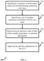
- the system 100 analyzes a symptom of performance behaviour and determines the underlying root cause, wherein the symptom of performance behaviour represents deviation of a measured performance of the AUT from a defined target performance i.e. the threshold of performance. Further, at step 304, the system 100 identifies a set of tuneable parameters related to the determined underlying root cause based one or more defined relationship between each of a plurality of pre-defined root causes and corresponding tuneable parameters, and the information pertaining to the relationship may be stored in the database 108. Further, at step 306, the system 100 determines an optimum value of each of the tuneable parameters in the set of tuneable parameters, wherein the determined optimum values of the tuneable parameters form optimum adjustments.
- the system 100 may perform the tuning separately for all components/sub-components that have been identified as required to be tuned, based on service demand ( D max ) each of the components/sub-components is handling at any instance, wherein the service demand represents amount of load.
- the system 100 may prioritize the component/sub-component for tuning based on decreasing value of D max , and the tuning may involve optimizing visit count and service time, by increasing capacity (in terms of parameters such as but not limited to processing speed, and memory allocation) to accommodate the service demand.
- the system 100 may retest the AUT with the defined workload, measure performance, recalculate the service demand and perform the optimization till all the components/sub-components of the AUT are able to accommodate the service demand.
- the system 100 dynamically performs the tuning as the service demand of the components and sub-components vary time to time.
- the system 100 applies the determined optimum adjustments on the AUT, to improve the (measured) performance to at least match the target performance.
- Applying the determined optimum adjustments on the AUT further involves the following steps. Initially, a total hardware and software resource requirement for the AUT is determined for a given workload, based on the determined optimum value of one or more tuneable parameters. Further, the system 100 determines an optimal configuration of the AUT and the hardware and software resources, based on a plurality of hardware and software resources matching the determined hardware and software resource requirement, for a given workload, based on the determined optimum value of the one or more tuneable parameters. The system 100 then determines a capacity and workload configurations for the plurality of hardware resources, based on the determined optimum value of the one or more tuneable parameters.
- the system 100 then generates the optimal configurations based on the total hardware resources requirement, a determined layout of the AUT, and the determined capacity and workload configurations.
- the system 100 may then recommend the determined optimal configuration to a user, via an appropriate user interface.
- the system 100 may automatically control/modify the configurations of the AUT based on the determined optimal configuration, to improve the performance of the AUT.
- the system 100 may attempt the performance tuning for a defined number of iterations. If the performance of the AUT is not matching the threshold of performance even after performing the tuning for the defined number of iterations, then the system 100 may recommend a design change to the user.
- the example scenarios are elaborated with reference to the components of an example implementation of the system 100 as given in FIG. 5 .
- the system 100 implementation in FIG. 5 includes a context extractor, a workload designer, a workload generator, a monitoring workbench, and a system optimizer, which are implementations of the components of system 100, and the various functions explained as part of the application performance tuning and benchmarking are distributed among the aforementioned components.
- Working of the system 100 under various scenarios are explained below. To understand the process better, consider the example AUT depicted in FIG. 7 .
- the embodiments of present disclosure herein address unresolved problem of application performance management.
- the embodiment thus provides a mechanism to measure performance of an Application Under Test (AUT), for varying load conditions.
- the embodiments herein further provide a mechanism of tuning the AUT if a measured performance is below a threshold of performance, for any load configuration.
- AUT Application Under Test
- the hardware device can be any kind of device which can be programmed including e.g. any kind of computer like a server or a personal computer, or the like, or any combination thereof.
- the device may also include means which could be e.g. hardware means like e.g. an application-specific integrated circuit (ASIC), a field-programmable gate array (FPGA), or a combination of hardware and software means, e.g.
- ASIC application-specific integrated circuit
- FPGA field-programmable gate array
- the means can include both hardware means and software means.
- the method embodiments described herein could be implemented in hardware and software.
- the device may also include software means.
- the embodiments may be implemented on different hardware devices, e.g. using a plurality of CPUs.
- the embodiments herein can comprise hardware and software elements.
- the embodiments that are implemented in software include but are not limited to, firmware, resident software, microcode, etc.
- the functions performed by various components described herein may be implemented in other components or combinations of other components.
- a computer-usable or computer readable medium can be any apparatus that can comprise, store, communicate, propagate, or transport the program for use by or in connection with the instruction execution system, apparatus, or device.
- a computer-readable storage medium refers to any type of physical memory on which information or data readable by a processor may be stored.
- a computer-readable storage medium may store instructions for execution by one or more processors, including instructions for causing the processor(s) to perform steps or stages consistent with the embodiments described herein.
- the term "computer-readable medium” should be understood to include tangible items and exclude carrier waves and transient signals, i.e., be non-transitory. Examples include random access memory (RAM), read-only memory (ROM), volatile memory, nonvolatile memory, hard drives, CD ROMs, DVDs, flash drives, disks, and any other known physical storage media.
Landscapes
- Engineering & Computer Science (AREA)
- Theoretical Computer Science (AREA)
- General Engineering & Computer Science (AREA)
- Physics & Mathematics (AREA)
- General Physics & Mathematics (AREA)
- Quality & Reliability (AREA)
- Computer Hardware Design (AREA)
- Software Systems (AREA)
- Computing Systems (AREA)
- Mathematical Physics (AREA)
- Debugging And Monitoring (AREA)
Applications Claiming Priority (1)
| Application Number | Priority Date | Filing Date | Title |
|---|---|---|---|
| IN202121036874 | 2021-08-14 |
Publications (3)
| Publication Number | Publication Date |
|---|---|
| EP4134817A1 true EP4134817A1 (de) | 2023-02-15 |
| EP4134817C0 EP4134817C0 (de) | 2025-04-30 |
| EP4134817B1 EP4134817B1 (de) | 2025-04-30 |
Family
ID=83232840
Family Applications (1)
| Application Number | Title | Priority Date | Filing Date |
|---|---|---|---|
| EP22188644.3A Active EP4134817B1 (de) | 2021-08-14 | 2022-08-04 | Verfahren und system zur leistungsverwaltung von verteilten softwareanwendungen |
Country Status (2)
| Country | Link |
|---|---|
| US (1) | US12430233B2 (de) |
| EP (1) | EP4134817B1 (de) |
Cited By (1)
| Publication number | Priority date | Publication date | Assignee | Title |
|---|---|---|---|---|
| WO2024188034A1 (zh) * | 2023-03-10 | 2024-09-19 | 腾讯科技(深圳)有限公司 | 设备配置的调控方法、装置和存储介质及电子设备 |
Families Citing this family (1)
| Publication number | Priority date | Publication date | Assignee | Title |
|---|---|---|---|---|
| CN119356963B (zh) * | 2024-12-25 | 2025-03-21 | 苏州吉呗思数据技术有限公司 | 自适应调整负载的系统测试方法、装置、设备以及产品 |
Citations (2)
| Publication number | Priority date | Publication date | Assignee | Title |
|---|---|---|---|---|
| WO2014025584A1 (en) * | 2012-08-07 | 2014-02-13 | Advanced Micro Devices, Inc. | System and method for tuning a cloud computing system |
| US20200293835A1 (en) * | 2019-03-13 | 2020-09-17 | Akamas S.R.L. | Method and apparatus for tuning adjustable parameters in computing environment |
Family Cites Families (6)
| Publication number | Priority date | Publication date | Assignee | Title |
|---|---|---|---|---|
| US8464224B2 (en) | 2009-06-30 | 2013-06-11 | Sap Ag | Integrated performance and load testing tool for application servers |
| US8930918B2 (en) | 2010-05-18 | 2015-01-06 | Tata Consultancy Services Limited | System and method for SQL performance assurance services |
| GB2504491A (en) * | 2012-07-30 | 2014-02-05 | Ibm | Remote debug service in a cloud environment |
| US9152532B2 (en) * | 2012-08-07 | 2015-10-06 | Advanced Micro Devices, Inc. | System and method for configuring a cloud computing system with a synthetic test workload |
| US9762461B2 (en) | 2013-07-09 | 2017-09-12 | Oracle International Corporation | Cloud services performance tuning and benchmarking |
| US10257275B1 (en) * | 2015-10-26 | 2019-04-09 | Amazon Technologies, Inc. | Tuning software execution environments using Bayesian models |
-
2022
- 2022-08-04 EP EP22188644.3A patent/EP4134817B1/de active Active
- 2022-08-08 US US17/818,122 patent/US12430233B2/en active Active
Patent Citations (2)
| Publication number | Priority date | Publication date | Assignee | Title |
|---|---|---|---|---|
| WO2014025584A1 (en) * | 2012-08-07 | 2014-02-13 | Advanced Micro Devices, Inc. | System and method for tuning a cloud computing system |
| US20200293835A1 (en) * | 2019-03-13 | 2020-09-17 | Akamas S.R.L. | Method and apparatus for tuning adjustable parameters in computing environment |
Non-Patent Citations (2)
| Title |
|---|
| DING ZUOHUA ET AL: "A software cybernetics approach to self-tuning performance of on-line transaction processing systems", JOURNAL OF SYSTEMS & SOFTWARE, ELSEVIER NORTH HOLLAND, NEW YORK, NY, US, vol. 124, 12 March 2016 (2016-03-12), pages 247 - 259, XP029839822, ISSN: 0164-1212, DOI: 10.1016/J.JSS.2016.03.012 * |
| J D MEIER ET AL: "Performance Testing Guidance for Web Applications", 1 January 2007 (2007-01-01), pages 1 - 221, XP055106205, Retrieved from the Internet <URL:http://perftestingguide.codeplex.com/downloads/get/17955> [retrieved on 20140307] * |
Cited By (1)
| Publication number | Priority date | Publication date | Assignee | Title |
|---|---|---|---|---|
| WO2024188034A1 (zh) * | 2023-03-10 | 2024-09-19 | 腾讯科技(深圳)有限公司 | 设备配置的调控方法、装置和存储介质及电子设备 |
Also Published As
| Publication number | Publication date |
|---|---|
| EP4134817C0 (de) | 2025-04-30 |
| EP4134817B1 (de) | 2025-04-30 |
| US20230078091A1 (en) | 2023-03-16 |
| US12430233B2 (en) | 2025-09-30 |
Similar Documents
| Publication | Publication Date | Title |
|---|---|---|
| US11573848B2 (en) | Identification and/or prediction of failures in a microservice architecture for enabling automatically-repairing solutions | |
| US9921952B2 (en) | Early risk identification in DevOps environments | |
| US10817283B1 (en) | Automated risk assessment for software deployment | |
| US10387798B2 (en) | Machine for development of analytical models | |
| JP7764096B2 (ja) | ソフトウェア・アップグレードがコンピューティング・デバイスに与える潜在的な影響を判定するための方法、コンピュータ・プログラム、および更新推奨コンピュータ・サーバ(ソフトウェア・アップグレードの安定性の推奨) | |
| US10614375B2 (en) | Machine for development and deployment of analytical models | |
| US11934947B2 (en) | Microservice management using machine learning | |
| US8560819B2 (en) | Software execution using multiple initialization modes | |
| JP2022100301A6 (ja) | ソフトウェア・アップグレードがコンピューティング・デバイスに与える潜在的な影響を判定するための方法、コンピュータ・プログラム、および更新推奨コンピュータ・サーバ(ソフトウェア・アップグレードの安定性の推奨) | |
| US11449407B2 (en) | System and method for monitoring computing platform parameters and dynamically generating and deploying monitoring packages | |
| US10514898B2 (en) | Method and system to develop, deploy, test, and manage platform-independent software | |
| EP4134817B1 (de) | Verfahren und system zur leistungsverwaltung von verteilten softwareanwendungen | |
| US10241902B2 (en) | Systems and methods for benchmark based cross platform service demand prediction | |
| US20250053446A1 (en) | Application prioritization system | |
| Khan et al. | Lads: Leveraging llms for ai-driven devops | |
| US20210141709A1 (en) | Automatic software behavior identification using execution record | |
| WO2018010565A1 (en) | Application resilience system and method thereof for applications deployed on platform | |
| CN119693119A (zh) | 规则引擎与状态机的融合方法、装置、计算机设备及存储介质 | |
| US10990413B2 (en) | Mainframe system structuring | |
| US20240103853A1 (en) | Code maintenance system | |
| EP4179428B1 (de) | Trace-identifizierung auf basis einer wartezeitkettenabdeckungsanalyse | |
| US20250028567A1 (en) | System and method for dynamically allocating computer resources to a data processing pipeline | |
| Truyen et al. | Optimal configuration of API resources in cloud native computing | |
| CN121722678A (zh) | 用于对项目代码进行测试的方法、介质和计算机程序产品 |
Legal Events
| Date | Code | Title | Description |
|---|---|---|---|
| PUAI | Public reference made under article 153(3) epc to a published international application that has entered the european phase |
Free format text: ORIGINAL CODE: 0009012 |
|
| STAA | Information on the status of an ep patent application or granted ep patent |
Free format text: STATUS: THE APPLICATION HAS BEEN PUBLISHED |
|
| AK | Designated contracting states |
Kind code of ref document: A1 Designated state(s): AL AT BE BG CH CY CZ DE DK EE ES FI FR GB GR HR HU IE IS IT LI LT LU LV MC MK MT NL NO PL PT RO RS SE SI SK SM TR |
|
| STAA | Information on the status of an ep patent application or granted ep patent |
Free format text: STATUS: REQUEST FOR EXAMINATION WAS MADE |
|
| 17P | Request for examination filed |
Effective date: 20230511 |
|
| RBV | Designated contracting states (corrected) |
Designated state(s): AL AT BE BG CH CY CZ DE DK EE ES FI FR GB GR HR HU IE IS IT LI LT LU LV MC MK MT NL NO PL PT RO RS SE SI SK SM TR |
|
| REG | Reference to a national code |
Ref country code: DE Ref legal event code: R079 Free format text: PREVIOUS MAIN CLASS: G06F0008770000 Ipc: G06F0011300000 Ref country code: DE Ref legal event code: R079 Ref document number: 602022013805 Country of ref document: DE Free format text: PREVIOUS MAIN CLASS: G06F0008770000 Ipc: G06F0011300000 |
|
| RIC1 | Information provided on ipc code assigned before grant |
Ipc: G06F 11/34 20060101ALI20241014BHEP Ipc: G06F 8/77 20180101ALI20241014BHEP Ipc: G06F 11/30 20060101AFI20241014BHEP |
|
| GRAP | Despatch of communication of intention to grant a patent |
Free format text: ORIGINAL CODE: EPIDOSNIGR1 |
|
| STAA | Information on the status of an ep patent application or granted ep patent |
Free format text: STATUS: GRANT OF PATENT IS INTENDED |
|
| INTG | Intention to grant announced |
Effective date: 20241223 |
|
| GRAS | Grant fee paid |
Free format text: ORIGINAL CODE: EPIDOSNIGR3 |
|
| GRAA | (expected) grant |
Free format text: ORIGINAL CODE: 0009210 |
|
| STAA | Information on the status of an ep patent application or granted ep patent |
Free format text: STATUS: THE PATENT HAS BEEN GRANTED |
|
| RAP3 | Party data changed (applicant data changed or rights of an application transferred) |
Owner name: TATA CONSULTANCY SERVICES LIMITED |
|
| AK | Designated contracting states |
Kind code of ref document: B1 Designated state(s): AL AT BE BG CH CY CZ DE DK EE ES FI FR GB GR HR HU IE IS IT LI LT LU LV MC MK MT NL NO PL PT RO RS SE SI SK SM TR |
|
| REG | Reference to a national code |
Ref country code: CH Ref legal event code: EP Ref country code: GB Ref legal event code: FG4D |
|
| REG | Reference to a national code |
Ref country code: IE Ref legal event code: FG4D |
|
| REG | Reference to a national code |
Ref country code: DE Ref legal event code: R096 Ref document number: 602022013805 Country of ref document: DE |
|
| U01 | Request for unitary effect filed |
Effective date: 20250430 |
|
| U07 | Unitary effect registered |
Designated state(s): AT BE BG DE DK EE FI FR IT LT LU LV MT NL PT RO SE SI Effective date: 20250508 |
|
| U20 | Renewal fee for the european patent with unitary effect paid |
Year of fee payment: 4 Effective date: 20250825 |
|
| PG25 | Lapsed in a contracting state [announced via postgrant information from national office to epo] |
Ref country code: ES Free format text: LAPSE BECAUSE OF FAILURE TO SUBMIT A TRANSLATION OF THE DESCRIPTION OR TO PAY THE FEE WITHIN THE PRESCRIBED TIME-LIMIT Effective date: 20250430 |
|
| PG25 | Lapsed in a contracting state [announced via postgrant information from national office to epo] |
Ref country code: NO Free format text: LAPSE BECAUSE OF FAILURE TO SUBMIT A TRANSLATION OF THE DESCRIPTION OR TO PAY THE FEE WITHIN THE PRESCRIBED TIME-LIMIT Effective date: 20250730 Ref country code: GR Free format text: LAPSE BECAUSE OF FAILURE TO SUBMIT A TRANSLATION OF THE DESCRIPTION OR TO PAY THE FEE WITHIN THE PRESCRIBED TIME-LIMIT Effective date: 20250731 |
|
| PG25 | Lapsed in a contracting state [announced via postgrant information from national office to epo] |
Ref country code: PL Free format text: LAPSE BECAUSE OF FAILURE TO SUBMIT A TRANSLATION OF THE DESCRIPTION OR TO PAY THE FEE WITHIN THE PRESCRIBED TIME-LIMIT Effective date: 20250430 |
|
| PG25 | Lapsed in a contracting state [announced via postgrant information from national office to epo] |
Ref country code: HR Free format text: LAPSE BECAUSE OF FAILURE TO SUBMIT A TRANSLATION OF THE DESCRIPTION OR TO PAY THE FEE WITHIN THE PRESCRIBED TIME-LIMIT Effective date: 20250430 |
|
| PGFP | Annual fee paid to national office [announced via postgrant information from national office to epo] |
Ref country code: CH Payment date: 20250901 Year of fee payment: 4 |
|
| PG25 | Lapsed in a contracting state [announced via postgrant information from national office to epo] |
Ref country code: RS Free format text: LAPSE BECAUSE OF FAILURE TO SUBMIT A TRANSLATION OF THE DESCRIPTION OR TO PAY THE FEE WITHIN THE PRESCRIBED TIME-LIMIT Effective date: 20250731 |
|
| PG25 | Lapsed in a contracting state [announced via postgrant information from national office to epo] |
Ref country code: IS Free format text: LAPSE BECAUSE OF FAILURE TO SUBMIT A TRANSLATION OF THE DESCRIPTION OR TO PAY THE FEE WITHIN THE PRESCRIBED TIME-LIMIT Effective date: 20250830 |
|
| PG25 | Lapsed in a contracting state [announced via postgrant information from national office to epo] |
Ref country code: SM Free format text: LAPSE BECAUSE OF FAILURE TO SUBMIT A TRANSLATION OF THE DESCRIPTION OR TO PAY THE FEE WITHIN THE PRESCRIBED TIME-LIMIT Effective date: 20250430 |
|
| PG25 | Lapsed in a contracting state [announced via postgrant information from national office to epo] |
Ref country code: CZ Free format text: LAPSE BECAUSE OF FAILURE TO SUBMIT A TRANSLATION OF THE DESCRIPTION OR TO PAY THE FEE WITHIN THE PRESCRIBED TIME-LIMIT Effective date: 20250430 |
|
| PG25 | Lapsed in a contracting state [announced via postgrant information from national office to epo] |
Ref country code: SK Free format text: LAPSE BECAUSE OF FAILURE TO SUBMIT A TRANSLATION OF THE DESCRIPTION OR TO PAY THE FEE WITHIN THE PRESCRIBED TIME-LIMIT Effective date: 20250430 |
|
| PLBE | No opposition filed within time limit |
Free format text: ORIGINAL CODE: 0009261 |
|
| STAA | Information on the status of an ep patent application or granted ep patent |
Free format text: STATUS: NO OPPOSITION FILED WITHIN TIME LIMIT |
|
| REG | Reference to a national code |
Ref country code: CH Ref legal event code: L10 Free format text: ST27 STATUS EVENT CODE: U-0-0-L10-L00 (AS PROVIDED BY THE NATIONAL OFFICE) Effective date: 20260311 |
|
| PG25 | Lapsed in a contracting state [announced via postgrant information from national office to epo] |
Ref country code: MC Free format text: LAPSE BECAUSE OF FAILURE TO SUBMIT A TRANSLATION OF THE DESCRIPTION OR TO PAY THE FEE WITHIN THE PRESCRIBED TIME-LIMIT Effective date: 20250430 |
|
| 26N | No opposition filed |
Effective date: 20260202 |