EP4134832A1 - Verbesserung der funktionalität einer vorrichtung mit begrenzten ressourcen - Google Patents
Verbesserung der funktionalität einer vorrichtung mit begrenzten ressourcen Download PDFInfo
- Publication number
- EP4134832A1 EP4134832A1 EP21191180.5A EP21191180A EP4134832A1 EP 4134832 A1 EP4134832 A1 EP 4134832A1 EP 21191180 A EP21191180 A EP 21191180A EP 4134832 A1 EP4134832 A1 EP 4134832A1
- Authority
- EP
- European Patent Office
- Prior art keywords
- attachment
- candidate
- specific
- response
- server
- Prior art date
- Legal status (The legal status is an assumption and is not a legal conclusion. Google has not performed a legal analysis and makes no representation as to the accuracy of the status listed.)
- Pending
Links
Images



Classifications
-
- G—PHYSICS
- G06—COMPUTING OR CALCULATING; COUNTING
- G06F—ELECTRIC DIGITAL DATA PROCESSING
- G06F15/00—Digital computers in general; Data processing equipment in general
- G06F15/16—Combinations of two or more digital computers each having at least an arithmetic unit, a program unit and a register, e.g. for a simultaneous processing of several programs
- G06F15/177—Initialisation or configuration control
Definitions
- Embodiments of the present disclosure relate to apparatus with limited resources and enhancing their functionality.
- Limited-resource apparatus are apparatus with limited processing and/or memory resources. Such apparatus are often used for performing specific functions at low cost and with low power consumption. They can be implemented using a microcontroller.
- the functionality is generally enhanced by replacing the apparatus with a new apparatus.
- an apparatus comprising means for:
- the one or more functions of the attachment are not accessible without the attachment-specific code.
- the candidate-specific form of the one or more commands is unique to a pool of a plurality of candidate attachments.
- the means are further configured to perform determining if the response of the attachment to the candidate-specific signaling matches an expected response of the candidate for the attachment to the one or more commands.
- the means are further configured to perform identifying the attachment as the candidate if the response of the attachment to the candidate-specific signaling matches an expected response of the candidate for the attachment to the one or more commands,
- the means are further configured to perform controlling the candidate-specific signaling on the one or more electrical connections to provide one or more commands in a form specific to a different candidate for the attachment, if the response of the attachment to the candidate-specific signaling does not match an expected response of the candidate for the attachment to the one or more commands.
- the means are further configured to perform communicating with a server to obtain, from the server, the attachment-specific code which, when loaded, configures the apparatus to access functions of the attachment.
- the means are further configured to perform receiving, from the server, instructions indicating the form of the one or more commands which is specific to the candidate for the attachment.
- the instructions relating to a first subset of candidates are received at a first time and the instructions relating to a second subset of candidates are received at a second time, wherein the second time is a time after it is determined that the attachment is not one of the candidates of the first subset.
- the means are further configured to perform:
- the means are further configured to perform detecting that one or more electrical connections with an attachment have been formed and controlling candidate-specific signaling on the one or more electrical connections in response.
- the candidates for the attachment are based upon one or more of:
- the one or more functions of the attachment are not accessible without the attachment-specific code.
- executable code that, when run on a computer, performs:
- the one or more functions of the attachment are not accessible without the attachment-specific code.
- a system comprising:
- the one or more functions of the attachment are not accessible without the attachment-specific code.
- server apparatus system for enabling transfer of attachment-specific code to apparatuses comprising:
- the one or more functions of the attachment are not accessible to the apparatus without the provided attachment-specific code.
- the means comprises a microcontroller configured to cause the performance of the apparatus.
- the means comprises at least one processor; and at least one memory including executable code, the at least one memory and executable code configured to, with the at least one processor, cause the performance of the apparatus.
- an apparatus 1 comprising means for: forming one or more electrical connections 5 with an attachment 3, such as an attachment device 3;
- the apparatus 1 provides a probe to a new attachment 3 and receives in reply a response, where the pairing of the probe-response can provide information on the identity of the new attachment 3.
- the probe (candidate-specific signaling 9) is specific to the candidate 23 for the attachment 3 (a putative/possible attachment).
- the response can be specific or non-specific.
- the pairing of the probe and response is sufficiently specific to confirm the identity of the attachment 3 as the candidate 23 for the attachment 3 or confirm the identity of the attachment 3 as not the candidate 23 for the attachment 3.
- the identity of the attachment 3 is used to load attachment-specific code 13 at the apparatus 1 to, at least partly, re-configure the apparatus 1.
- the newly reconfigured apparatus 1 can now access one or more functions of the attachment 3 that were not accessible without the reconfiguration by the attachment-specific code 13.
- the attachment-specific code is obtained from a remote server 17.
- information 25 configuring the probe (candidate-specific signaling 9) and/or information configuring the expected response 51 to the probe can be obtained from the remote server 17 or a different server.
- a remote server 17 can provide, to multiple apparatuses 1, services comprising supplying attachment-specific code 13, and configuring probes (candidate-specific signaling 9) and/or the expected response 51 to the probes.
- FIG 1 illustrates an example of an apparatus 1.
- the apparatus comprises an interface 4 for forming one or more electrical connections 5 with an attachment 3.
- the apparatus 1 comprises a controller 7 for controlling candidate-specific signaling 9 on the one or more electrical connections 5 to provide one or more commands in a form specific to a candidate for the attachment 3, for confirming, based on a response 11 of the attachment 3 to the candidate-specific signaling 9, an identity of the attachment 3 as the candidate for the attachment 3; and for loading/receiving attachment-specific code 13, dependent upon the identity of the attachment 3 to configure the apparatus 1 to access one or more functions of the attachment 3 not accessible without the attachment-specific code 13.
- the interface 4 for forming one or more electrical connections 5 with an attachment 3 is a physical interface that forms physical interconnections with a corresponding interface of an attachment 3.
- the physical interconnections are used for the electrical connections 5 with an attachment 3.
- each physical interconnection provides an electrical connection.
- I/O pins can be used to form the physical interconnections and provide the electrical connections 5.
- the I/O pins form one or more physical interconnections between the apparatus 1 and the attachment 3 for electrical signaling.
- the pool comprises a plurality of candidates for the attachment 3.
- the candidate-specific signaling 9 comprises N commands where N ⁇ 1.
- the N commands are provided in a candidate-specific form.
- the candidate-specific form of the N commands is unique to the pool of the plurality of candidates 23. That is, the candidate-specific form for one candidate 23 is not shared with another candidate 23 in the pool.
- the candidate-specific signaling 9 is physical layer signaling.
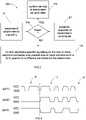
- the candidate-specific signaling 9 in FIG 4 is, for example, voltage level signaling.
- Control of candidate-specific signaling 9 on the one or more electrical connections 5 to provide one or more commands in a form specific to a candidate 23 for the attachment 3 is achieved, for example, by controlling time-variation of voltage levels on one or more general purpose I/O pins. This can be achieved by periodically pulling a voltage to a HIGH level and pulling the voltage to a LOW level. Multiple commands have a form characterized by a sequence of time-varying voltage signals.
- an electrical connection 5 for example “pin 1” or “pin 3" can be used first to provide candidate-specific signaling 9 to the attachment 3 from the apparatus 1 and then subsequently used to provide a response 11 from the attachment 3 to the apparatus 1.
- an electrical connection 5, for example a "pin 2”, that is connected but not used first to provide candidate-specific signaling 9 to the attachment 3 from the apparatus 1 can be subsequently used to provide a response 11 from the attachment 3 to the apparatus 1.
- the apparatus 1 can, for example, be a microcontroller, a single-board computer (SBC), a processor and/or circuitry, or any combination thereof, with one or more electrical connections, such as I/O pins.
- the apparatus can be any computer apparatus, such as a wireless communication device and/or an loT (Internet-of-Things) device, with one or more electrical connections, such as I/O pins.
- the apparatus 1 is without an operating system and does not have a device discovery mechanism.
- the attachment 3 is a hardware module/extension for augmenting functionality of the apparatus 1. It can be a sensor module/device, a communication module/device, a memory module/device, a battery module/device, a power source module/device, a user interface module/device, a user input module/device, loT module/device, etc. or any combination thereof.
- the attachment 3 can be implemented with or without its own one or more processors, memories and computer program code, that are together configured to cause the attachment to function based on the one or more computer program code.
- FIG 2 illustrates an example of a method 100 that enables functionality of the apparatus 1 to be extended by connecting an attachment 3.
- the attachment 3 can be a removable or replaceable attachment.
- the method 100 re-configures the apparatus 1 to access one or more functions of the attachment 3 not previously accessible by loading attachment-specific code 13 at the apparatus 1.
- the method 100 comprises controlling candidate-specific signaling 9 on one or more electrical connections 5, formed between the apparatus 1 and the attachment 3, to provide one or more commands in a form specific to a candidate for the attachment 3.
- the method 100 comprises confirming, based on a response 11 of the attachment 3 to the candidate-specific signaling 9, an identity of the attachment 3 as the candidate 23 for the attachment 3.
- the method 100 comprises loading attachment-specific code 13, dependent upon the identity of the attachment 3, to configure the apparatus 1 to access one or more functions of the attachment 3. In some instances, the attachment 3 is not accessible without the attachment-specific code 13 installed/configured in the apparatus 1.
- Block 102 controls candidate-specific signaling on one or more electrical connections 5 to provide one or more commands in a form specific to a different candidate 23 for the attachment 3.
- the candidate-specific signaling 9 provides one or more commands in a form specific to a candidate 23 for the attachment 3. If the candidate 23 changes, the candidate-specific signaling 9 is different and provides one or more commands in a different form specific to the new candidate 23 for the attachment 3.
- the candidate-specific signaling 9 it is possible for the candidate-specific signaling 9 to be different and use the same or different one or more electrical connections 5.
- the candidate-specific signaling 9 It is possible for the candidate-specific signaling 9 to be different and command, logically, the same or different functions. However, the candidate-specific signaling 9 is physically different (different at the physical layer) having a form specific to the new candidate for the attachment 3.
- the method 100 can loop through blocks 102, 104, 108 until a pool of available candidate attachments is exhausted or identity of the attachment 3 is confirmed as the identity of the current candidate 23 for the attachment 3 at block 104.
- FIG 3 illustrates in more detail block 104.
- the method comprises detecting a response 11 of/from the attachment 3 to the candidate-specific signaling 9, which provide one or more commands in a form specific to a candidate 23 for the attachment 3.
- the response 11 enables confirmation of an identity of the attachment 3 as the candidate 23 for the attachment 3.
- the method comprises determining if the response 11 of the attachment 3 to the candidate-specific signaling 9 matches an expected response 51 of the candidate for the attachment 3 to the one or more commands.
- the method moves to sub-block 112 where the attachment 3 is identified as the candidate.
- the candidate identity is confirmed as the true identity enabling the loading and/or storing of attachment-specific code 13, dependent upon the identity of the attachment 3, to configure the apparatus 1 to access one or more functions of the attachment 3, that may not be accessible without the attachment-specific code 13.
- the method moves to sub-block 114 and the attachment 3 is identified as NOT the candidate.
- the candidate identity is confirmed as NOT the true identity.
- the method controls candidate-specific signaling 9 on one or more electrical connections 5 to provide one or more commands in a form specific to a different candidate 23 for the attachment 3. This can for example be achieved by the method 100 being restarted 108 at block 102 in respect of a different candidate 23 for the attachment 3.
- Block 102 then controls candidate-specific signaling on one or more electrical connections 5 to provide one or more commands in a form specific to a different candidate 23 for the attachment 3.
- the method 100 can loop through blocks 102, 104, 108 until a pool of available candidate attachments is exhausted or identity of the attachment is confirmed as the identity of the current candidate 23 for the attachment 3 at sub-block 110 of block 104.
- FIG 5 illustrates an example of the method 100 that enables functionality of an apparatus 1 to be extended by connecting an attachment 3.
- the attachment 3 can be a removable or replaceable attachment.
- the method configures the apparatus 1 to access 118 one or more functions of the attachment 3 not previously accessible by loading attachment-specific code 13 at the apparatus 1.
- the method 100 comprises controlling candidate-specific signaling 9 on one or more electrical connections 5, formed between the apparatus 1 and the attachment 3, to provide one or more commands in a form specific to a candidate for the attachment 3.
- the method 100 comprises detecting a response 11 of the attachment 3 to the candidate-specific signaling 9.
- the detected response 11 is used to attempt to confirm an identity of the attachment 3 as the candidate 23 for the attachment 3. It is determined if the response 11 of the attachment 3 to the candidate-specific signaling 9 matches an expected response 51 of the candidate for the attachment 3 to the one or more commands.
- the method abandons the current candidate 23 for the attachment and selects a new, different candidate 23' for the attachment and will control candidate-specific signaling 9' on one or more electrical connections 5 to provide one or more commands in a form specific to the new, different candidate 23' for the attachment 3.
- the method 100 comprises controlling candidate-specific signaling 9' on one or more electrical connections 5, formed between the apparatus 1 and the attachment 3, to provide one or more commands in a form specific to the candidate 23' for the attachment 3.
- the method 100 comprises detecting a response 1 1' of the attachment 3 to the candidate-specific signaling 9' of block 102A.
- the detected response 11' is used to attempt to confirm an identity of the attachment 3 as the candidate 23' for the attachment 3. It is determined if the response 11' of the attachment 3 to the candidate-specific signaling 9' matches an expected response 51' of the candidate 23' for the attachment 3 to the one or more commands.
- the attachment 3 is identified as the candidate.
- the candidate identity is confirmed as the true identity enabling, at block 106, the loading/storing of attachment-specific code 13, dependent upon the identity of the attachment 3, to configure the apparatus 1 to access one or more functions of the attachment 3 not accessible without the attachment-specific code 13.
- the apparatus 1 accesses one or more functions of the attachment 3 which may not be accessible without the attachment-specific code 13.
- FIG 6 illustrates an apparatus 1 and an attachment 3 as previously described.
- the FIG additionally illustrates a server 17.
- the server 17, apparatus 1 and the attachment 3 together form a system 70.
- the server 17 can be used to augment the functionality of the apparatus 1 by communicating with the apparatus 1.
- the attachment-specific code 13 can be provided by the server 17.
- the candidate-specific signaling 9 can be provided by the server 17.
- the expected response 51 can be provided by the server 17.
- the apparatus 1 is configured to communicate wirelessly with the server.
- the server 17 is configured for direct wireless communication with the apparatus 1 and in other examples the server 17 is configured for indirect wireless communication with the apparatus 1 via a network or proxy.
- the apparatus 1 comprises a radio transceiver 15 configured for direct communication with a radio transceiver 19 of the server 17.
- the apparatus 1 is configured to obtain, from the server 17, the attachment-specific code 13 which, when loaded in the apparatus 1, configures the apparatus 1 to access functions of the attachment 3, which may not be accessible without the attachment-specific code 13.
- the apparatus 1 can be configured to receive, from the server, instructions 25 for defining candidate-specific signaling 9, for example, indicating the form and/or list of the one or more commands which is specific to the candidate 23 for the attachment 3.
- the instructions 25 specify the form of the one or more commands which is specific to the candidate 23 for the attachment 3
- the apparatus 1 can be configured to receive, from the server 17, an expected response 51 of the candidate 23 for the attachment 3 to the form of the one or more commands, which is specific to the candidate 23 for the attachment 3.
- the apparatus 1 compares/matches the response 11 of the attachment 3 to the candidate-specific signaling with the expected response 51. In this way, the expected response 51 is used to determine if the response 11 of the attachment 3 to the candidate-specific signaling 9 matches an expected response 51 of the candidate 23 for the attachment 3 to the one or more commands.
- the apparatus 1 is configured to report a result of the comparison/matching to the server 17 to enable the server to identify the correct attachment-specific code 13.
- FIG 6 is therefore illustrative of an example of a system 70 comprising:
- the candidate 23 for the attachment 3 can be selected from a pool of candidates 21 for the attachment.
- the form of one or more commands provided by the candidate-specific signaling 9 is unique for the attachment 3 amongst the pool of candidates 21.
- the server 17 is shared by the apparatus 1 and other apparatuses 1 for enabling transfer of attachment-specific code 13 to the apparatus 1 and the other apparatuses 1 as described above.
- Each of the apparatuses 1 can operate as described above and the server 17 can operate independently, as described above, for each apparatus 1.
- the server 17 can therefore communicate separately with multiple apparatuses 1, for example, using radio transceiver 19 and/or via a wired network.
- Each apparatus 1 is configured to form one or more physical connections 5 between the respective apparatus 1 and a respective attachment 3 for electrical signaling between the respective apparatus 1 and the respective attachment 3.
- FIG 7 illustrates an example of the method 100 when the apparatus 1 can communicate with the server 17.
- the server 17 determines, for example, after receiving / in response to a request from the apparatus 1, a candidate 23 for the attachment 3 from a pool of candidates for the attachment 3 and provides, to the apparatus 1, instructions 25 for defining candidate-specific signaling 9 for the determined candidate 23 and candidate-specific expected responses 51 to the candidate-specific signaling 9 for the determined candidate 23 for the attachment 3.
- the candidate-specific signaling 9 comprises one or more commands in a form specific to the determined candidate 23 for the attachment 3.
- the candidate-specific expected response 51 enables determination, e.g. by comparing, at the apparatus 1, if a response 11 of the attachment 3 to the respective candidate-specific signaling 9 matches a respective expected response 51 of the candidate 23 for the attachment 3 to the candidate-specific signaling 9 to identify the attachment 3 as the candidate 23 for the attachment 3.
- the blocks 102, 104, 110 are as previously described.
- the response 11 of the attachment 3 to the candidate-specific signaling 9 matches the expected response 51 of the candidate 23 for the attachment 3 to the one or more commands, and the attachment 3 is identified as the candidate.
- the candidate identity is confirmed as the true identity.
- the apparatus 1 sends to the server attachment-specific signaling 53 identifying the attachment 3.
- the server 17 receives from the apparatus 1 attachment-specific signaling 53 identifying the attachment 3, accesses 116 attachment-specific code 13 dependent upon the identification of the attachment 3 and provides the attachment-specific code 13 to the apparatus 1 to cause the apparatus 1 to load 106 the provided attachment-specific code 13 to configure the apparatus 1 to access one or more functions of the attachment 3 not accessible to the apparatus 1 without the provided attachment-specific code 13.
- the server 17 provides, to the apparatus 1, instructions 25 for defining candidate-specific signaling 9 for each candidate 23 in the pool of candidates.
- Each candidate-specific signaling 9 comprises one or more commands in a form specific to a candidate 23 for the attachment 3.
- the server 17 also provides, to the apparatus 1, candidate-specific expected responses 51 to the candidate-specific signaling 9 for each candidate 23 in the pool.
- Each candidate-specific expected response 51 enables determination at the apparatus 1 if a response 11 of the attachment 3 to the respective candidate-specific signaling 9 matches a respective expected response 51 of the candidate 23 for the attachment 3 to the candidate-specific signaling 9 to identify the attachment 3 as the candidate 23 for the attachment 3.
- the server provides instructions 25 for defining candidate-specific signaling 9 to the apparatus 1 for each candidate 23 for the attachment 3 in a first subset S 1 of candidate attachments and provides candidate-specific expected responses 51 to the candidate-specific signaling 9 to the apparatus 1 for each candidate 23 for the attachment 3 in the first subset S 1 of candidate attachments.
- Each candidate-specific signaling 9 comprises one or more commands in a form specific to the determined candidate 23 for the attachment 3.
- Each candidate-specific expected response 51 enables determination at the apparatus 1 if a response 11 of the attachment 3 to the respective candidate-specific signaling 9 matches a respective expected response 51 of the candidate 23 for the attachment 3 to the candidate-specific signaling 9 to identify the attachment 3 as the candidate 23 for the attachment 3. This allows the batch sequential processing of the first subset S 1 of candidate attachments by the apparatus 1 as enabled, for example, by the loop 108 in FIG 2 .
- the apparatus requests 182 at block 180 more candidates.
- the server at a second time t 2 after the first time, provides instructions 25 for defining candidate-specific signaling 9 to the apparatus 1 for each candidate 23 for the attachment 3 in a second subset S 2 of candidate attachments and provides candidate-specific expected responses 51 to the candidate-specific signaling 9 to the apparatus 1 for each candidate 23 for the attachment 3 in the second subset S 2 of candidate attachments.
- the first subset S 1 and the second subset S 2 do not intersect.
- Each candidate-specific signaling 9 comprises one or more commands in a form specific to the determined candidate 23 for the attachment 3.
- Each candidate-specific expected response 51 enables determination at the apparatus 1 if a response 11 of the attachment 3 to the respective candidate-specific signaling 9 matches a respective expected response 51 of the candidate 23 for the attachment 3 to the candidate-specific signaling 9 to identify the attachment 3 as the candidate 23 for the attachment 3. This allows the batch sequential processing of the second S 2 and more subsets of candidate attachments by the apparatus 1 as enabled, for example, by the loop 108 in FIG 2 .
- a subset S i of candidate attachments can comprise M i candidates 23 for the attachment 3, where M i ⁇ 1.
- a subset S i of candidate attachments can therefore comprise one or more candidates 23 for the attachment 3.
- FIG 9 illustrates an example of initiation of the method 100.
- the apparatus 1 is configured to detect 120 that one or more new electrical connections 5 have been formed at an interface 4, for I/O pins, used to connect an attachment 3 to the apparatus 1 and, in response to the detection, initiate the method 100.
- the apparatus 1 can send a message 55 to the server 17.
- the initial stage of the method 100 is to identify a suitable candidate. This can be performed solely at the apparatus 1, solely at a server 17 or jointly between the apparatus 1 and the server, for example, the server can identify a pool of candidates and the apparatus can identify an initial candidate from the pool.
- the initial candidates for the attachment 3, or the pool of candidates for the attachment can be based upon one or more of:
- the apparatus 1 can be configured to determine a protocol used by the attachment 3 by:
- Fig 10A illustrates an example of the controller 7 of the apparatus 1.
- Implementation of a controller 7 may be as one or more controller circuitries/processors 33.
- the controller 7 may be implemented in hardware alone, have certain aspects in software including firmware alone or can be a combination of hardware and software (including firmware).
- controller 7 may be implemented using instructions that enable hardware functionality, for example, by using executable code 37, that may be stored on one or more computer readable storage medium 35 (disk, memory etc.), to be executed in one or more general-purpose or special-purpose processors 33.
- executable code 37 may be stored on one or more computer readable storage medium 35 (disk, memory etc.), to be executed in one or more general-purpose or special-purpose processors 33.
- the processor 33 is configured to read from and write to the memory 35.
- the processor 33 may also comprise an output interface via which data and/or commands are output by the processor 33 and an input interface via which data and/or commands are input to the processor 33.
- the memory 35 stores a computer program, such as an executable code 37, comprising computer program instructions (computer program code),that controls the operation of the apparatus 1 when loaded into the processor 33.
- the executable code 37 provides the logic and routines that enables the apparatus to perform the methods illustrated in Figs 1 to 9 .
- the processor 33 by reading the memory 35 is able to load and execute the executable code 37.
- the apparatus 1 therefore comprises:
- the apparatus 1 therefore comprises:
- the computer program such as an executable code 37
- the delivery mechanism 39 may be, for example, a machine-readable medium, a computer-readable medium, a non-transitory computer-readable storage medium, a computer program product, a memory device, a record medium such as a Compact Disc Read-Only Memory (CD-ROM) or a Digital Versatile Disc (DVD) or a solid-state memory, an article of manufacture that comprises or tangibly embodies the executable code 37.
- the delivery mechanism may be a signal configured to reliably transfer the executable code 37.
- Executable code 37 causes an apparatus to perform at least the following or for performing at least the following:
- the executable code 37 may be comprised in a non-transitory computer readable medium, a computer program product, a machine-readable medium. In some but not necessarily all examples, the executable code 37 may be distributed over more than one computer program.
- memory 35 is illustrated as a single component/circuitry it may be implemented as one or more separate components/circuitry some or all of which may be integrated/removable and/or may provide permanent/semi-permanent/ dynamic/cached storage.
- processor 33 is illustrated as a single component/circuitry it may be implemented as one or more separate components/circuitry some or all of which may be integrated/removable.
- the processor 33 may be a single core or multi-core processor.
- references to 'computer-readable storage medium', 'computer program product', 'tangibly embodied computer program' etc. or a 'controller', 'computer', 'processor' etc. should be understood to encompass not only computers having different architectures such as single /multi- processor architectures and sequential (Von Neumann)/parallel architectures but also specialized circuits such as field-programmable gate arrays (FPGA), application specific circuits (ASIC), signal processing devices and other processing circuitry.
- References to computer program, instructions, executable code etc. should be understood to encompass software for a programmable processor or firmware such as, for example, the programmable content of a hardware device whether instructions for a processor, or configuration settings for a fixed-function device, gate array or programmable logic device etc.
- circuitry may refer to one or more or all of the following:
- circuitry also covers an implementation of merely a hardware circuit or processor and its (or their) accompanying software and/or firmware.
- circuitry also covers, for example and if applicable to the particular claim element, a baseband integrated circuit for a mobile device or a similar integrated circuit in a server, a cellular network device, or other computing or network device.
- the blocks illustrated in the Figs 2 , 3 , 5 and 7 to 9 may represent steps in a method and/or sections of code in the executable code 37.
- the illustration of a particular order to the blocks does not necessarily imply that there is a required or preferred order for the blocks and the order and arrangement of the block may be varied. Furthermore, it may be possible for some blocks to be omitted.
- the server 17 can be embedded in new or existing Internet of Things (loT) Hubs/servers (for example used in home automation, industrial automation, farming automation, etc.) or instantiated independently in the cloud or in edge-cloud/server/computer. It could also be embedded in an end-user device, for example, a mobile telephone/communication device, laptop, tablet, wireless access point/router, server, vehicle, etc. or any combination thereof.
- LoT Internet of Things
- a remote database can be used to store some or all of the data provided by the server 17 to the apparatus 1.
- the remote database can be shared by multiple servers 17.
- the data provided by the server 17 to the apparatus 1 can then be provided on request by the local server 17, possibly based on detected behavior and microcontroller type in the apparatus 1.
- the apparatus 1 i.e. its microcontroller
- the bootload memory part will remain static.
- the apparatus 1 can allows In-System Programming (ISP), and can be remotely resettable.
- ISP In-System Programming
- the DETECT command controls candidate-specific signaling 9 on the one or more electrical connections 5 to provide one or more commands in a form specific to a candidate 23 for the attachment 3.
- the microcontroller 7 receives and runs a DTIS (Duck-Typing Instruction Set) in order to detect potential new hardware attachments 3 and reports the results to the server 17.
- DTIS Digit-Typing Instruction Set
- the RESET command causes loading of attachment-specific code 13 at the microcontroller 7, dependent upon the identity of the attachment 3 to configure the apparatus 1 to access one or more functions of the attachment 3 not accessible without the attachment-specific code.
- the microcontroller 7 receives and loads new attachment-specific code 13 and eventually resets itself, this operation is required to update the apparatus 1 functionalities, for example by updating the internal code and adding new libraries.
- a low-power computational apparatus 1 can be updated and upgraded (with new hardware attachments 3) automatically or manually (user-initiated).
- a Duck-Typing Instruction Set is a specific procedure including a low-level sequence (electrical signals) defined for a given microcontroller 7 and a piece of hardware to be tested (such as a sensor) for identification/typing purpose.
- the DTIS object exchanged between the server 17 and the apparatus 1 using the DETECT command comprises:
- the apparatus 1 can detect activity on free I/O pins and report it to the server 17 (these steps may be replaced by a user-initiated installation request, from the Hub). Then the server 17 either uses its local data to select corresponding DTIS candidates (for the given microcontroller) or may fetch data from an external database.
- a DETECT command is sent to the apparatus 1 as a response to the initial request, carrying a set of DTIS (wrt. memory restrictions) in order to "probe" the new hardware attachment 3.
- the DTIS object(s) are executed by the apparatus 1.
- the apparatus 1 sequentially tests the hardware attachment 3 by running the DTIS.
- the apparatus 1 controls candidate-specific signaling 9 on the one or more electrical connections 5 to provide one or more commands in a form specific to a candidate 23 for the attachment 3.
- Each response 11 by the attachment 3 to candidate-specific signaling 9 is tested against a respective expected response 51 and a confirmation of the hardware attachment 3 identity is immediately notified to the server 17 (positive feedback).
- Additional candidate 23 tests may be requested to the server 17, e.g. loT Hub, until a positive feedback from the new hardware attachment 3 is observed, that is, for example, that the response 11 from the hardware attachment 3 matches the expected response 51.
- a positive match is notified to the server 17 so it can trigger the RESET command carrying the new client code (hardware driver + reporting code).
- the server 17 loads the new client code 13 and resets the microcontroller of the apparatus 1, the new hardware attachment 3 is then able to communicate with the apparatus 1 which can report the new data to the server 17.
- test result positive feedback
- whole test set of instructions as described by the DTIS
- the whole test is preferably carried out by the apparatus 1 because of the very strict timings required by the low-level signaling protocols (microseconds intervals).
- loT devices will be reusable and will evolve and adapt to their environment with the possibility to update by adding one or more hardware extensions (i.e. an attachment device 3), while keeping cheap microcontroller-enabled assets.
- the solution is ecological with more multi-function apparatuses 1, less power consumption, and less bandwidth use.
- the solution enables loT ecosystems to evolve existing assets instead of growing by adding or replacing assets.
- the solution offers greater security as apparatus 1 can be updated to fix bugs and various security flaws.
- the apparatus 1 can be, or can be used in, a "smart" home appliance (such as refrigerator, washing machine, or coffee maker, etc.) and/or a house, vehicle, loT device, industrial process device, etc. or any device as a part of the aforementioned, such as door, alarm system, shutters, electrical motor, valve, sensor, camera, etc., which could be dynamically enhanced with one or more extra physical/software capabilities by simply plugging a right extension hardware module, such as the attachment device 3, on an exposed electrical connector interface 4 of an apparatus 1. Then apparatus 1, augmented with the connected hardware attachment 3, can detect and install the required firmware 13. This can enable new functionalities at the apparatus 1 based on one or more defined functionalities of the attachment device 3.
- a "smart" home appliance such as refrigerator, washing machine, or coffee maker, etc.
- a house, vehicle, loT device, industrial process device, etc. or any device as a part of the aforementioned such as door, alarm system, shutters, electrical motor, valve, sensor, camera, etc.
- the refrigerator will be able to scan and report stored products; the washing machine will be able to measure the water hardness by a water hardness sensor; the coffee maker will play music by a loudspeaker; the NFC-enabled door will connect with Bluetooth too by a Bluetooth communication device; the alarm system will be enriched with an IR-camera; the shutters will be controlled by a light detector, the vehicle will be enriched with a LIDAR (Light Detection and Ranging) device, etc.
- LIDAR Light Detection and Ranging
- the apparatus 1 can also be used in Industrial-loT.
- the ability to easily and dynamically enhance connected pieces of hardware e.g. sensors, actuators
- the server 17 can be logically hosted on a local loT Hub/server. However, the server 17 could also be running on the end-user device (e.g. smartphone, laptop, tablet, vehicle) and support an operator who is interacting/enhancing devices on the field.
- the end-user device e.g. smartphone, laptop, tablet, vehicle
- module' refers to a unit or apparatus that excludes certain parts/components that would be added by an end manufacturer or a user.
- the attachment 3 can be a hardware module.
- an apparatus comprises means for:
- an apparatus comprises means for:
- a method comprises:
- a computer program when run on a computer, performs:
- a system comprises:
- a server system for enabling transfer of attachment-specific code to one or more apparatuses comprises means for:
- the above-described examples find application as enabling components of: automotive systems; telecommunication systems; electronic systems including consumer electronic products; distributed computing systems; media systems for generating or rendering media content including audio, visual and audio visual content and mixed, mediated, virtual and/or augmented reality; personal systems including personal health systems or personal fitness systems; navigation systems; user interfaces also known as human machine interfaces; networks including cellular, non-cellular, and optical networks; ad-hoc networks; the internet; the internet of things; virtualized networks; and related software and services.
- a property of the instance can be a property of only that instance or a property of the class or a property of a sub-class of the class that includes some but not all of the instances in the class. It is therefore implicitly disclosed that a feature described with reference to one example but not with reference to another example, can where possible be used in that other example as part of a working combination but does not necessarily have to be used in that other example.
- 'a' or 'the' is used in this document with an inclusive not an exclusive meaning. That is any reference to X comprising a/the Y indicates that X may comprise only one Y or may comprise more than one Y unless the context clearly indicates the contrary. If it is intended to use 'a' or 'the' with an exclusive meaning then it will be made clear in the context. In some circumstances the use of 'at least one' or 'one or more' may be used to emphasis an inclusive meaning but the absence of these terms should not be taken to infer any exclusive meaning.
- the presence of a feature (or combination of features) in a claim is a reference to that feature or (combination of features) itself and also to features that achieve substantially the same technical effect (equivalent features).
- the equivalent features include, for example, features that are variants and achieve substantially the same result in substantially the same way.
- the equivalent features include, for example, features that perform substantially the same function, in substantially the same way to achieve substantially the same result.
Landscapes
- Engineering & Computer Science (AREA)
- Computer Hardware Design (AREA)
- Theoretical Computer Science (AREA)
- Software Systems (AREA)
- Physics & Mathematics (AREA)
- General Engineering & Computer Science (AREA)
- General Physics & Mathematics (AREA)
- Mobile Radio Communication Systems (AREA)
Priority Applications (1)
| Application Number | Priority Date | Filing Date | Title |
|---|---|---|---|
| EP21191180.5A EP4134832A1 (de) | 2021-08-13 | 2021-08-13 | Verbesserung der funktionalität einer vorrichtung mit begrenzten ressourcen |
Applications Claiming Priority (1)
| Application Number | Priority Date | Filing Date | Title |
|---|---|---|---|
| EP21191180.5A EP4134832A1 (de) | 2021-08-13 | 2021-08-13 | Verbesserung der funktionalität einer vorrichtung mit begrenzten ressourcen |
Publications (1)
| Publication Number | Publication Date |
|---|---|
| EP4134832A1 true EP4134832A1 (de) | 2023-02-15 |
Family
ID=77338489
Family Applications (1)
| Application Number | Title | Priority Date | Filing Date |
|---|---|---|---|
| EP21191180.5A Pending EP4134832A1 (de) | 2021-08-13 | 2021-08-13 | Verbesserung der funktionalität einer vorrichtung mit begrenzten ressourcen |
Country Status (1)
| Country | Link |
|---|---|
| EP (1) | EP4134832A1 (de) |
Citations (3)
| Publication number | Priority date | Publication date | Assignee | Title |
|---|---|---|---|---|
| US5655148A (en) * | 1994-05-27 | 1997-08-05 | Microsoft Corporation | Method for automatically configuring devices including a network adapter without manual intervention and without prior configuration information |
| US20040081099A1 (en) * | 2002-06-24 | 2004-04-29 | Stuart Patterson | Identification system and method for recognizing any one of a number of different types of devices |
| WO2020062227A1 (en) * | 2018-09-30 | 2020-04-02 | Siemens Aktiengesellschaft | Method and device for recognizing apparatus and computer readable storage medium and program |
-
2021
- 2021-08-13 EP EP21191180.5A patent/EP4134832A1/de active Pending
Patent Citations (4)
| Publication number | Priority date | Publication date | Assignee | Title |
|---|---|---|---|---|
| US5655148A (en) * | 1994-05-27 | 1997-08-05 | Microsoft Corporation | Method for automatically configuring devices including a network adapter without manual intervention and without prior configuration information |
| US20040081099A1 (en) * | 2002-06-24 | 2004-04-29 | Stuart Patterson | Identification system and method for recognizing any one of a number of different types of devices |
| WO2020062227A1 (en) * | 2018-09-30 | 2020-04-02 | Siemens Aktiengesellschaft | Method and device for recognizing apparatus and computer readable storage medium and program |
| US20210311746A1 (en) * | 2018-09-30 | 2021-10-07 | Siemens Aktiengesellschaft | Method and device for recognizing apparatus and computer readable storage medium and program |
Similar Documents
| Publication | Publication Date | Title |
|---|---|---|
| US10568150B2 (en) | Techniques for automatically establishing a long-lasting connection across computing devices configured for short-range wireless communication | |
| US11074066B2 (en) | Apparatus and method for managing software updates of electronic devices | |
| US10922251B2 (en) | Electronic device and method for controlling same | |
| US20170134405A1 (en) | Dynamic Honeypot System | |
| US20170083358A1 (en) | Methods and apparatus to automatically configure monitoring of a virtual machine | |
| US20180034914A1 (en) | System and method for controlling heterogeneous internet of things (iot) devices using single application | |
| US20180063257A1 (en) | Devices in a flexible registration framework | |
| US20140343915A1 (en) | Test environment configuration apparatus and method of operating network simulation apparatus using same | |
| US10775754B2 (en) | Method for creating prototype and apparatus therefor | |
| US9800619B2 (en) | Registration framework for connected consumer devices | |
| CN113672441A (zh) | 对智能设备的测试方法及装置 | |
| US20150146706A1 (en) | Remotely Provisioning And Operating A Headless WIFI Device | |
| CN112068856A (zh) | 用于控制车辆的更新的装置及方法 | |
| US11677637B2 (en) | Contextual update compliance management | |
| EP3352495B1 (de) | Elektronische vorrichtung und verfahren zur bereitstellung eines ereignisverwaltungsdienstes | |
| US20140380313A1 (en) | Method and device for loading android virtual machine application | |
| US10999376B2 (en) | Simulating parallel mock rest services with single server | |
| WO2018140658A1 (en) | Contextual application interactions with connected devices | |
| US11182139B2 (en) | System and method for production readiness verification and monitoring | |
| US10657245B2 (en) | Dynamically controlling access to devices | |
| US20230229454A1 (en) | Tracking device user account information | |
| US20180322032A1 (en) | App software audience impersonation for software testing | |
| KR20190052279A (ko) | 네트워크 서비스 지속성 관리 | |
| US20250254525A1 (en) | Device Enrollment using Serialized Application | |
| EP4134832A1 (de) | Verbesserung der funktionalität einer vorrichtung mit begrenzten ressourcen |
Legal Events
| Date | Code | Title | Description |
|---|---|---|---|
| PUAI | Public reference made under article 153(3) epc to a published international application that has entered the european phase |
Free format text: ORIGINAL CODE: 0009012 |
|
| STAA | Information on the status of an ep patent application or granted ep patent |
Free format text: STATUS: THE APPLICATION HAS BEEN PUBLISHED |
|
| AK | Designated contracting states |
Kind code of ref document: A1 Designated state(s): AL AT BE BG CH CY CZ DE DK EE ES FI FR GB GR HR HU IE IS IT LI LT LU LV MC MK MT NL NO PL PT RO RS SE SI SK SM TR |
|
| STAA | Information on the status of an ep patent application or granted ep patent |
Free format text: STATUS: REQUEST FOR EXAMINATION WAS MADE |
|
| 17P | Request for examination filed |
Effective date: 20230811 |
|
| RBV | Designated contracting states (corrected) |
Designated state(s): AL AT BE BG CH CY CZ DE DK EE ES FI FR GB GR HR HU IE IS IT LI LT LU LV MC MK MT NL NO PL PT RO RS SE SI SK SM TR |