EP4135099A1 - Dispositif et procédé de gestion de batterie - Google Patents
Dispositif et procédé de gestion de batterie Download PDFInfo
- Publication number
- EP4135099A1 EP4135099A1 EP21864503.4A EP21864503A EP4135099A1 EP 4135099 A1 EP4135099 A1 EP 4135099A1 EP 21864503 A EP21864503 A EP 21864503A EP 4135099 A1 EP4135099 A1 EP 4135099A1
- Authority
- EP
- European Patent Office
- Prior art keywords
- profile
- battery
- positive electrode
- prediction
- capacity
- Prior art date
- Legal status (The legal status is an assumption and is not a legal conclusion. Google has not performed a legal analysis and makes no representation as to the accuracy of the status listed.)
- Granted
Links
Images






Classifications
-
- H—ELECTRICITY
- H01—ELECTRIC ELEMENTS
- H01M—PROCESSES OR MEANS, e.g. BATTERIES, FOR THE DIRECT CONVERSION OF CHEMICAL ENERGY INTO ELECTRICAL ENERGY
- H01M10/00—Secondary cells; Manufacture thereof
- H01M10/42—Methods or arrangements for servicing or maintenance of secondary cells or secondary half-cells
- H01M10/48—Accumulators combined with arrangements for measuring, testing or indicating the condition of cells, e.g. the level or density of the electrolyte
-
- G—PHYSICS
- G01—MEASURING; TESTING
- G01R—MEASURING ELECTRIC VARIABLES; MEASURING MAGNETIC VARIABLES
- G01R31/00—Arrangements for testing electric properties; Arrangements for locating electric faults; Arrangements for electrical testing characterised by what is being tested not provided for elsewhere
- G01R31/36—Arrangements for testing, measuring or monitoring the electrical condition of accumulators or electric batteries, e.g. capacity or state of charge [SoC]
- G01R31/385—Arrangements for measuring battery or accumulator variables
- G01R31/387—Determining ampere-hour charge capacity or SoC
- G01R31/388—Determining ampere-hour charge capacity or SoC involving voltage measurements
-
- G—PHYSICS
- G01—MEASURING; TESTING
- G01R—MEASURING ELECTRIC VARIABLES; MEASURING MAGNETIC VARIABLES
- G01R31/00—Arrangements for testing electric properties; Arrangements for locating electric faults; Arrangements for electrical testing characterised by what is being tested not provided for elsewhere
- G01R31/36—Arrangements for testing, measuring or monitoring the electrical condition of accumulators or electric batteries, e.g. capacity or state of charge [SoC]
-
- G—PHYSICS
- G01—MEASURING; TESTING
- G01R—MEASURING ELECTRIC VARIABLES; MEASURING MAGNETIC VARIABLES
- G01R31/00—Arrangements for testing electric properties; Arrangements for locating electric faults; Arrangements for electrical testing characterised by what is being tested not provided for elsewhere
- G01R31/36—Arrangements for testing, measuring or monitoring the electrical condition of accumulators or electric batteries, e.g. capacity or state of charge [SoC]
- G01R31/3644—Constructional arrangements
- G01R31/3648—Constructional arrangements comprising digital calculation means, e.g. for performing an algorithm
-
- G—PHYSICS
- G01—MEASURING; TESTING
- G01R—MEASURING ELECTRIC VARIABLES; MEASURING MAGNETIC VARIABLES
- G01R31/00—Arrangements for testing electric properties; Arrangements for locating electric faults; Arrangements for electrical testing characterised by what is being tested not provided for elsewhere
- G01R31/36—Arrangements for testing, measuring or monitoring the electrical condition of accumulators or electric batteries, e.g. capacity or state of charge [SoC]
- G01R31/392—Determining battery ageing or deterioration, e.g. state of health
-
- H—ELECTRICITY
- H01—ELECTRIC ELEMENTS
- H01M—PROCESSES OR MEANS, e.g. BATTERIES, FOR THE DIRECT CONVERSION OF CHEMICAL ENERGY INTO ELECTRICAL ENERGY
- H01M10/00—Secondary cells; Manufacture thereof
- H01M10/42—Methods or arrangements for servicing or maintenance of secondary cells or secondary half-cells
-
- H—ELECTRICITY
- H01—ELECTRIC ELEMENTS
- H01M—PROCESSES OR MEANS, e.g. BATTERIES, FOR THE DIRECT CONVERSION OF CHEMICAL ENERGY INTO ELECTRICAL ENERGY
- H01M10/00—Secondary cells; Manufacture thereof
- H01M10/42—Methods or arrangements for servicing or maintenance of secondary cells or secondary half-cells
- H01M10/425—Structural combination with electronic components, e.g. electronic circuits integrated to the outside of the casing
-
- H—ELECTRICITY
- H01—ELECTRIC ELEMENTS
- H01M—PROCESSES OR MEANS, e.g. BATTERIES, FOR THE DIRECT CONVERSION OF CHEMICAL ENERGY INTO ELECTRICAL ENERGY
- H01M10/00—Secondary cells; Manufacture thereof
- H01M10/42—Methods or arrangements for servicing or maintenance of secondary cells or secondary half-cells
- H01M10/44—Methods for charging or discharging
-
- H—ELECTRICITY
- H01—ELECTRIC ELEMENTS
- H01M—PROCESSES OR MEANS, e.g. BATTERIES, FOR THE DIRECT CONVERSION OF CHEMICAL ENERGY INTO ELECTRICAL ENERGY
- H01M10/00—Secondary cells; Manufacture thereof
- H01M10/42—Methods or arrangements for servicing or maintenance of secondary cells or secondary half-cells
- H01M10/425—Structural combination with electronic components, e.g. electronic circuits integrated to the outside of the casing
- H01M2010/4271—Battery management systems including electronic circuits, e.g. control of current or voltage to keep battery in healthy state, cell balancing
-
- H—ELECTRICITY
- H01—ELECTRIC ELEMENTS
- H01M—PROCESSES OR MEANS, e.g. BATTERIES, FOR THE DIRECT CONVERSION OF CHEMICAL ENERGY INTO ELECTRICAL ENERGY
- H01M2220/00—Batteries for particular applications
- H01M2220/20—Batteries in motive systems, e.g. vehicle, ship, plane
-
- Y—GENERAL TAGGING OF NEW TECHNOLOGICAL DEVELOPMENTS; GENERAL TAGGING OF CROSS-SECTIONAL TECHNOLOGIES SPANNING OVER SEVERAL SECTIONS OF THE IPC; TECHNICAL SUBJECTS COVERED BY FORMER USPC CROSS-REFERENCE ART COLLECTIONS [XRACs] AND DIGESTS
- Y02—TECHNOLOGIES OR APPLICATIONS FOR MITIGATION OR ADAPTATION AGAINST CLIMATE CHANGE
- Y02E—REDUCTION OF GREENHOUSE GAS [GHG] EMISSIONS, RELATED TO ENERGY GENERATION, TRANSMISSION OR DISTRIBUTION
- Y02E60/00—Enabling technologies; Technologies with a potential or indirect contribution to GHG emissions mitigation
- Y02E60/10—Energy storage using batteries
Definitions
- the present disclosure relates to a battery management apparatus and method, and more particularly, to a battery management apparatus and method for generating a positive electrode profile and a battery profile for a battery cell in a non-destructive manner.
- Batteries commercially available at present include nickel-cadmium batteries, nickel hydrogen batteries, nickel-zinc batteries, lithium batteries and the like.
- the lithium batteries are in the limelight since they have almost no memory effect compared to nickel-based batteries and also have very low self-charging rate and high energy density.
- the battery cell Since the battery cell is degraded as it is used, in order to accurately estimate the state of charge (SOC) and/or state of health (SOH) for the degraded battery cell, various profiles are required for analyzing the degree of degradation of the battery cell. For example, when a battery profile, a positive electrode profile, and a negative electrode profile for a battery cell are provided, the degree of degradation of the battery cell may be analyzed most accurately.
- SOC state of charge
- SOH state of health
- a positive electrode and a negative electrode are disassembled from the battery cell, the positive electrode and the negative electrode are washed, and then a positive electrode half cell and a negative electrode half cell are reassembled so that a positive electrode profile and a negative electrode profile are respectively obtained from the reassembled positive and negative electrode half cells through an experimental method such as a 3-electrode system. It took a considerable amount of time to obtain a positive electrode profile and a negative electrode profile through this process, and in particular, there is a problem in that the battery cell is exposed to the risk of explosion when the battery cell is disassembled.
- the present disclosure is designed to solve the problems of the related art, and therefore the present disclosure is directed to providing a battery management apparatus and method, which may obtain a positive electrode profile by suitably adjusting a preset negative electrode profile and obtain a battery profile based on the obtained positive electrode profile.
- a battery management apparatus comprising: a measuring unit configured to measure voltage and capacity of a battery cell; a profile generating unit configured to generate a battery profile representing a correspondence between the voltage and the capacity measured by the measuring unit and generate a positive electrode profile of the battery cell based on the generated battery profile and a reference negative electrode profile and a reference negative electrode differential profile preset for the battery cell; and a control unit configured to receive the generated positive electrode profile from the profile generating unit, derive a conversion function representing conversion information from the reference positive electrode profile preset for the battery cell to the generated positive electrode profile, generate a positive electrode prediction profile for the battery cell from the reference positive electrode profile based on the derived conversion function, and generate a battery prediction profile for the battery cell based on the generated positive electrode prediction profile.
- the profile generating unit may be configured to convert the battery profile into a battery differential profile representing a correspondence between the capacity and a differential voltage for the capacity, adjust the reference negative electrode differential profile to correspond to the battery differential profile, adjust the reference negative electrode profile to correspond to the adjusted negative electrode differential profile, and generate the positive electrode profile based on the adjusted negative electrode profile and the battery profile.
- the profile generating unit may be configured to determine a plurality of reference peaks in the battery differential profile and adjust the reference negative electrode differential profile such that a capacity of a plurality of target peaks preset in the reference negative electrode differential profile becomes identical to a capacity of a corresponding reference peak.
- the profile generating unit may be configured to adjust the reference negative electrode differential profile by adjusting an offset corresponding to a minimum capacity of the reference negative electrode differential profile and a scale representing an entire capacity region of the reference negative electrode differential profile.
- the profile generating unit may be configured to adjust the reference negative electrode profile to correspond to the adjusted negative electrode differential profile by applying change information of the offset and the scale for the adjusted negative electrode differential profile to the reference negative electrode profile.
- the control unit may be configured to generate the battery prediction profile by calculating a difference between a voltage of the positive electrode prediction profile and a voltage of the adjusted negative electrode profile for the same capacity.
- the control unit may be configured to generate the battery prediction profile by calculating a difference between a voltage of the positive electrode prediction profile and a voltage of the reference negative electrode profile for the same capacity.
- the conversion function may be configured to convert a voltage per capacity of the reference positive electrode profile into a voltage per capacity of the generated positive electrode profile, for the same capacity.
- control unit may be configured to derive a conversion prediction function based on a voltage change amount per capacity between the plurality of conversion functions and generate the positive electrode prediction profile by applying the derived conversion prediction function to the reference positive electrode profile.
- the control unit may be configured to derive the conversion prediction function for a target point and generate the positive electrode prediction profile for the target point by applying the derived conversion prediction function to the reference positive electrode profile.
- the profile generating unit may be configured to generate the battery profile and generate the positive electrode profile at every preset cycle.
- the control unit may be configured to derive a conversion function between each of a plurality of positive electrode profiles generated by the profile generating unit until a current cycle and the reference positive electrode profile, derive the conversion prediction function based on the plurality of derived conversion functions, generate the positive electrode prediction profile by using the derived conversion prediction function and the reference positive electrode profile until a next cycle arrives, and then generate the battery prediction profile.
- a battery pack according to another aspect of the present disclosure may comprise the battery management apparatus according to an aspect of the present disclosure.
- a battery management method may comprise: a measuring step of measuring voltage and capacity of a battery cell; a battery profile generating step of generating a battery profile representing a correspondence between the voltage and the capacity measured in the measuring step; a positive electrode profile generating step of generating a positive electrode profile of the battery cell based on the battery profile generated in the battery profile generating step and a reference negative electrode profile and a reference negative electrode differential profile preset for the battery cell; a conversion function deriving step of deriving a conversion function representing conversion information from the reference positive electrode profile preset for the battery cell to the generated positive electrode profile; a positive electrode prediction profile generating step of generating a positive electrode prediction profile for the battery cell from the reference positive electrode profile based on the conversion function derived in the conversion function deriving step; and a battery prediction profile generating step of generating a battery prediction profile for the battery cell based on the positive electrode prediction profile generated in the positive electrode prediction profile generating step.
- the battery management apparatus may estimate a battery profile by generating a positive electrode prediction profile based on a generated battery profile and generating a battery prediction profile based on the generated positive electrode prediction profile. Due to this, the battery prediction profile may be generated even at a cycle point in which a battery profile is not directly generated based on the capacity and voltage of the battery cell. Accordingly, since a profile for analyzing the degradation of the battery cell may be secured at more various cycle points, the accuracy of the degradation analysis for the battery cell may be improved.
- control unit refers to a unit that processes at least one function or operation, and may be implemented by hardware, software, or a combination of hardware and software.
- FIG. 1 is a diagram schematically showing a battery management apparatus 100 according to an embodiment of the present disclosure.
- FIG. 2 is a diagram showing an exemplary configuration of a battery pack 1 including the battery management apparatus 100 according to an embodiment of the present disclosure.
- the battery management apparatus 100 may include a measuring unit 110, a profile generating unit 120, and a control unit 130.
- the measuring unit 110 may be configured to measure voltage and capacity of the battery cell B.
- the unit of voltage may be [V]
- the unit of capacity may be [mAh].
- a battery cell B means one independent cell that includes a negative electrode terminal and a positive electrode terminal and is physically separable.
- one pouch-type lithium polymer cell may be regarded as a battery cell B.
- the measuring unit 110 may measure the voltage of the battery by measuring voltages at both ends of the battery cell B, respectively. Also, the measuring unit 110 may measure the current applied to the battery cell B and the charging time while the battery cell B is being charged. In addition, the measuring unit 110 may measure the capacity of the battery cell B based on the measured current of the battery cell B and the charging time.
- the measuring unit 110 may be connected to a first sensing line SL1, a second sensing line SL2, and a third sensing line SL3.
- the measuring unit 110 may measure the voltage of the battery cell B through the first sensing line SL1 and the second sensing line SL2.
- the measuring unit 110 may be connected to a current measuring unit A through the third sensing line SL3, and may measure the current of the battery cell B through the current measuring unit A.
- the measuring unit 110 may include a timer capable of measuring the charging time while measuring the current of the battery cell B.
- the profile generating unit 120 may be configured to receive the measured voltage and capacity from the measuring unit 110.
- the profile generating unit 120 may be communicatively connected to the measuring unit 110.
- the profile generating unit 120 may receive the voltage and capacity for the battery cell B from the measuring unit 110.
- the profile generating unit 120 may be configured to generate a battery profile (Pb) representing the correspondence between the voltage and the capacity measured by the measuring unit 110.
- FIG. 3 is a diagram schematically showing a battery profile (Pb) and a reference negative electrode profile (Pa) according to an embodiment of the present disclosure.
- FIG. 3 is a diagram schematically showing the battery profile (Pb) and the reference negative electrode profile (Pa) in a graph form.
- FIG. 3 is a diagram schematically showing an X-Y graph when a capacity is set to X and a voltage is set to Y.
- the battery profile (Pb) may be a profile configured to indicate the correspondence between the voltage and the capacity of the battery cell B measured at the same time by the measuring unit 110.
- the profile generating unit 120 may be configured to generate a positive electrode profile of the battery cell B based on the generated battery profile (Pb) and a reference negative electrode profile (Pa) and a reference negative electrode differential profile (Pa_d) preset for the battery cell B.
- the reference negative electrode profile (Pa) may be a profile configured to indicate the correspondence between the negative electrode voltage and capacity of the battery cell B in the beginning of life (BOL) state. That is, the reference negative electrode profile (Pa) is a profile representing the correspondence between the voltage and the capacity of a negative electrode half-cell in the BOL state.
- the reference negative electrode profile (Pa) may be generated in advance through a charge/discharge experiment on the negative electrode half-cell.
- the reference negative electrode differential profile (Pa_d) may be a differential profile of the reference negative electrode profile (Pa) with respect to capacity.
- the reference negative electrode differential profile (Pa_d) may be a profile configured to indicate the correspondence between the capacity of the BOL negative electrode cell and the differential voltage.
- the differential voltage is a differential value of voltage with respect to capacity, and may be expressed as "dV/dQ", with the unit of [V/mAh]. That is, the differential voltage may be a value representing an instantaneous rate of change of voltage with respect to capacity.
- the battery profile (Pb) may be expressed as a difference between the voltage of the positive electrode profile and the voltage of the negative electrode profile for the same capacity.
- the positive electrode profile may be expressed as the sum of the voltage of the battery profile (Pb) and the voltage of the negative electrode profile for the same capacity.
- the profile generating unit 120 may generate a positive electrode profile from the generated battery profile (Pb) in consideration of the reference negative electrode profile (Pa) and the reference negative electrode differential profile (Pa_d). Specific details of the embodiment in which the profile generating unit 120 generates a positive electrode profile will be described later.
- the control unit 130 may be configured to receive the generated positive electrode profile from the profile generating unit 120.
- control unit 130 and the profile generating unit 120 may be communicatively connected.
- control unit 130 may receive the positive electrode profile from the profile generating unit 120.
- the control unit 130 may be configured to derive a conversion function representing conversion information from the reference positive electrode profile preset for the battery cell B to the generated positive electrode profile.
- the reference positive electrode profile (Pc) corresponds to the reference negative electrode profile (Pa), and may be a profile configured to indicate the correspondence between voltage and capacity of the positive electrode of the battery cell B in the BOL state. That is, the reference positive electrode profile (Pc) may be a profile configured to indicate the correspondence between voltage and capacity of the positive electrode half-cell in the BOL state.
- the reference positive electrode profile (Pc) may be generated in advance through a charge/discharge experiment on the positive electrode half-cell.
- the conversion function may be configured to convert a voltage per capacity of the reference positive electrode profile (Pc) to a voltage per capacity of the generated positive electrode profile for the same capacity. That is, when the derived conversion function is applied to the reference positive electrode profile (Pc), the positive electrode profile generated by the profile generating unit 120 may be generated.
- control unit 130 may derive a conversion function capable of converting the reference positive electrode profile (Pc) to the generated positive electrode profile by comparing voltages of the reference positive electrode profile (Pc) and the positive electrode profile generated by the profile generating unit 120 for the same capacity.
- the profile generating unit 120 generates a battery profile (Pb) and a positive electrode profile at the 100 th cycle point and the 200 th cycle point, respectively.
- the control unit 130 may derive a first conversion function (f1) corresponding to the 100 th cycle point by comparing the positive electrode profile generated at the 100 th cycle point with the reference positive electrode profile (Pc).
- the control unit 130 may derive a second conversion function (f2) corresponding to the 200 th cycle point by comparing the positive electrode profile generated at the 200 th cycle point with the reference positive electrode profile (Pc).
- the control unit 130 may be configured to generate a positive electrode prediction profile (Pc_e) for the battery cell B from the reference positive electrode profile (Pc) based on the derived conversion function.
- control unit 130 may derive a conversion prediction function (fe) by using the derived conversion function.
- the conversion prediction function (fe) may be a conversion function estimated by the control unit 130. That is, the conversion prediction function (fe) may be a function for generating the positive electrode prediction profile (Pc_e) for the battery cell B at a point of time when the positive electrode profile is not generated by the profile generating unit 120.
- the positive electrode prediction profile (Pc_e) is a positive electrode profile estimated for the battery cell B, and it may be a prediction profile not generated by the profile generating unit 120 but estimated when the control unit 130 applies the derived conversion prediction function (fe) to the reference positive electrode profile (Pc).
- control unit 130 may compare the plurality of conversion functions to derive the correspondence between the plurality of conversion functions.
- control unit 130 may derive the conversion prediction function (fe) according to the derived correspondence.
- the control unit 130 may generate a positive electrode prediction profile (Pc_e) by applying the derived conversion prediction function (fe) to the reference positive electrode profile (Pc).
- control unit 130 derives the first conversion function (f1)at the 100 th cycle point and the second conversion function (f2) at the 200 th cycle point.
- the control unit 130 may determine change information of the conversion function according to the cycle by comparing the first conversion function (f1)and the second conversion function (f2).
- the control unit 130 may derive conversion prediction functions (fe) for cycle points excluding the 100 th cycle point and the 200 th cycle point, based on the determined change information.
- the control unit 130 may derive conversion prediction functions (fe) for time points after the 200 th cycle point.
- the control unit 130 may be configured to generate a battery prediction profile (Pb_e) for the battery cell B based on the generated positive electrode prediction profile (Pc_e).
- control unit 130 derives a conversion prediction function (fe) of the 250 th cycle point.
- the control unit 130 may generate a positive electrode prediction profile (Pc_e) of the 250 th cycle point by applying the derived conversion prediction function (fe) to the reference positive electrode profile (Pc).
- control unit 130 may generate a battery prediction profile (Pb_e) of the 250 th cycle point based on the positive electrode prediction profile (Pc_e) of the 250 th cycle point.
- the battery management apparatus 100 may generate a battery profile (Pb) by measuring the capacity and voltage of the battery cell B when it is intended to acquire the battery profile (Pb).
- a battery profile (Pb) by measuring the capacity and voltage of the battery cell B at every cycle
- charging and discharging of the battery cell B must be controlled in order to obtain an accurate battery profile (Pb). Therefore, there is a problem that the use of the battery cell B is too limited.
- a low charge/discharge rate of 0.05 C-rate to 0.3 C-rate is required, which may cause excessive restrictions in the use of the battery cell B.
- the battery management apparatus 100 may estimate the battery profile (Pb) by generating the positive electrode prediction profile (Pc_e) based on the generated battery profile (Pb) and generating the battery prediction profile (Pb_e) based on the generated positive electrode prediction profile (Pc_e). Due to this, the battery prediction profile (Pb_e) may be generated even at a cycle point where the battery profile (Pb) is not directly generated based on the capacity and voltage of the battery cell B. Therefore, since a profile for analyzing the degradation of the battery cell B may be secured at more various cycle points, the accuracy of the degradation analysis for the battery cell B may be improved.
- the battery management apparatus 100 may generate the positive electrode prediction profile (Pc_e) and the battery prediction profile (Pb_e) for a future time point by deriving the conversion prediction function (fe) based on the correspondence between the derived conversion functions. That is, since the battery management apparatus 100 may generate the positive electrode prediction profile (Pc_e) and the battery prediction profile (Pb_e) for a future time point, there is an advantage that various profiles may be secured to analyze the expected degradation of the battery cell B.
- control unit 130 provided to the battery management apparatus 100 may selectively include processors known in the art, application-specific integrated circuit (ASIC), other chipsets, logic circuits, registers, communication modems, data processing devices, and the like to execute various control logic performed in the present disclosure.
- ASIC application-specific integrated circuit
- the control unit 130 may be implemented as a set of program modules.
- the program module may be stored in a memory and executed by the control unit 130.
- the memory may be located inside or out of the control unit 130 and may be connected to the control unit 130 by various well-known means.
- the battery management apparatus 100 may further include a storage unit 140.
- the storage unit 140 may store data necessary for operation and function of each component of the battery management apparatus 100, data generated in the process of performing the operation or function, or the like.
- the storage unit 140 may store the program and data necessary for the profile generating unit 120 to generate the battery profile (Pb) and the positive electrode profile and for the control unit 130 to generate the positive electrode prediction profile (Pc_e) and the battery prediction profile (Pb_e).
- the storage unit 140 is not particularly limited in its kind as long as it is a known information storage means that can record, erase, update and read data.
- the information storage means may include RAM, flash memory, ROM, EEPROM, registers, and the like.
- the storage unit 140 may store program codes in which processes executable by the measuring unit 110, the profile generating unit 120 and the control unit 130 are defined.
- the profile generating unit 120 generates a positive electrode profile
- the profile generating unit 120 may be configured to convert the battery profile (Pb) into a battery differential profile (Pb_d) representing the correspondence between the capacity and a differential voltage for the capacity.
- the profile generating unit 120 may convert the battery profile (Pb) representing the correspondence between the capacity and voltage of the battery cell B into the battery differential profile (Pb_d) representing the correspondence between the capacity of the battery cell B and the differential voltage.
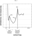
- FIG. 4 is a diagram schematically showing the battery differential profile (Pb_d) according to an embodiment of the present disclosure.
- FIG. 4 is a diagram showing the battery differential profile (Pb_d) in a graph form.
- FIG. 4 is a diagram schematically showing an X-Y graph when the capacity of the battery cell B is set to the X axis and the differential voltage is set to the Y axis.
- the profile generating unit 120 may be configured to adjust the reference negative electrode differential profile (Pa_d) to correspond to the battery differential profile (Pb_d).
- FIG. 5 is a diagram schematically showing the negative electrode differential profile (Pa_d) according to an embodiment of the present disclosure.
- FIG. 5 is a diagram showing the reference negative electrode differential profile (Pa_d) in a graph form.
- FIG. 5 is a diagram schematically showing an X-Y graph when the capacity of the negative electrode half-cell is set to the X axis and the differential voltage is set to the Y axis.
- the profile generating unit 120 may be configured to determine a plurality of reference peaks in the battery differential profile (Pb_d).
- the reference peak may be a peak of which the instantaneous rate of change of the differential voltage with respect to capacity is 0 and the differential voltage is largest in the corresponding capacity region.
- the profile generating unit 120 may determine a peak of which the instantaneous rate of change of the differential voltage with respect to capacity in the first capacity region is 0 and the differential voltage is largest as the first reference peak (RP1).
- the profile generating unit 120 may determine a peak of which the instantaneous rate of change of the differential voltage with respect to capacity in the second capacity region is 0 and the differential voltage is largest as the second reference peak (RP2).
- first capacity region and the second capacity region may be preset not to overlap each other.
- information on the first capacity region and the second capacity region may be stored in advance in the profile generating unit 120 and/or the storage unit 140.
- the first capacity region and the second capacity region may be capacity regions configured in consideration of the electrochemical characteristics of the battery cell B.
- a predetermined capacity region in which the first reference peak (RP1) may appear may be preset as the first capacity region
- a predetermined capacity region in which the second reference peak (RP2) may appear may be preset as the second capacity region.
- the first capacity region may be set as a capacity region of 0% to 30% in the entire capacity region (min to max1 region) of the negative electrode half-cell of the BOL battery cell B.
- the first capacity region may be preset as a region of "min” to "min + [(max1 - min) ⁇ 0.3 ⁇ ".
- the second capacity region may be set as a capacity region of 40% to 60% in the entire capacity region (min to max1 region) of the negative electrode half-cell of the BOL battery cell B.
- the second capacity region may be preset as "min + ⁇ (maxi - min) ⁇ 0.4 ⁇ " to "min + ⁇ (maxi - min) ⁇ 0.6 ⁇ " region.
- the profile generating unit 120 may be configured to adjust the reference negative electrode differential profile (Pa_d) such that a capacity of a plurality of target peaks preset in the reference negative electrode differential profile (Pa_d) becomes equal to a capacity of a corresponding reference peak.
- FIG. 6 is a diagram schematically showing a negative electrode differential profile (Pa_d2) adjusted by the battery management apparatus 100 according to an embodiment of the present disclosure.
- the profile generating unit 120 may be configured to adjust the reference negative electrode differential profile (Pa_d) by adjusting the offset corresponding to the minimum capacity of the reference negative electrode differential profile (Pa_d) and the scale representing the entire capacity region of the reference negative electrode differential profile (Pa_d).
- the offset may correspond to the minimum capacity among the entire capacity region of the reference negative electrode differential profile (Pa_d), and the scale may correspond to the entire capacity region of the reference negative electrode differential profile (Pa_d).
- the profile generating unit 120 may adjust the offset and/or the scale of the reference negative electrode differential profile (Pa_d) so that the capacity of the plurality of target peaks included in the reference negative electrode differential profile (Pa_d) becomes equal to the capacity of the corresponding reference peak.
- the capacity of the first reference peak (RP1) included in the battery differential profile (Pb_d) may be a1 [mAh]
- the capacity of the second reference peak (RP2) may be a2 [mAh].
- the capacity of the first target peak (TP1) included in the reference negative electrode differential profile (Pa_d) may be b1 [mAh]
- the capacity of the second target peak (TP2) may be b2 [mAh].
- the profile generating unit 120 may adjust the offset and/or the scale of the reference negative electrode differential profile (Pa_d) such that the capacity of the first target peak (TP1) becomes a1 [mAh] and the capacity of the second target peak (TP2) becomes a2 [mAh].
- the shape of the negative electrode profile may be maintained even if the battery cell B is degraded. That is, even if the battery cell B is degraded, the scale of the entire capacity region of the negative electrode profile is changed as a whole without changing only the scale of some capacity region of the entire capacity region of the negative electrode profile. Thus, even if the battery cell B is degraded, the shape of the negative electrode profile may be maintained. Accordingly, the profile generating unit 120 may obtain the adjusted negative electrode differential profile (Pa_d2) corresponding to the battery differential profile (Pb_d) by adjusting the offset and/or the scale of the reference negative electrode differential profile (Pa_d).
- the profile generating unit 120 may be configured to adjust the reference negative electrode profile (Pa) to correspond to the adjusted negative electrode differential profile (Pa_d2).
- the profile generating unit 120 may be configured to adjust the reference negative electrode profile (Pa) to correspond to the adjusted negative electrode differential profile (Pa_d2) by applying the change information of the offset and the scale for the adjusted negative electrode differential profile (Pa_d2) to the reference negative electrode profile (Pa).
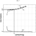
- FIG. 7 is a diagram schematically showing an example where a positive electrode profile (Pc2) is generated by the battery management apparatus 100 according to an embodiment of the present disclosure.
- the profile generating unit 120 may generate an adjusted negative electrode profile (Pa2) by applying the offset and the scale of the adjusted negative electrode differential profile (Pa_d2) to the reference negative electrode profile (Pa).
- the profile generating unit 120 may be configured to generate the positive electrode profile (Pc2) based on the adjusted negative electrode profile (Pa2) and the battery profile (Pb).
- the profile generating unit 120 may generate the positive electrode profile (Pc2) by summing the voltage per capacity of the battery profile (Pb) and the voltage per capacity of the adjusted negative electrode profile (Pa2) for the same capacity.
- the voltage corresponding to the S1 [mAh] capacity in the adjusted negative electrode profile (Pa2) may be Va [V]
- the voltage corresponding to the S1 [mAh] capacity in the battery profile (Pb) may be Vb [V].
- the profile generating unit 120 may obtain Vc [V] by calculating "Va + Vb”.
- the profile generating unit 120 may generate the positive electrode profile (Pc2) in which the voltage corresponding to the S1 [mAh] capacity is Vc [V].
- the first target peak (TP1) and the second target peak (TP2) included in the negative electrode differential profile (Pa_d) may be related to the staging phenomenon in which lithium ions are extracted during the discharge process.
- a staging process in which lithium ions contained between graphite layers are extracted is performed.
- the staging process in the discharge process proceeds from a high stage to a low stage according to the extraction reaction of lithium ions.
- the staging process is performed in the order of stage IV, stage III, stage II, and stage I.
- the capacity (b1) of the first target peak (TP1) included in the reference negative electrode differential profile (Pa_d) may correspond to the negative electrode capacity when the stage III state progresses.
- the capacity (b1) of the first target peak (TP1) may correspond to the negative electrode capacity when the stage II and stage III states that are coexisting are converted to the stage III state.
- the capacity (b2) of the second target peak (TP2) included in the reference negative electrode differential profile (Pa_d) may correspond to the negative electrode capacity when the stage II state progresses.
- the capacity (b2) of the second target peak (TP2) may correspond to the negative electrode capacity when the stage I and stage II states that are coexisting are converted to the stage II state.
- the capacity corresponding to the first target peak (TP1) and the second target peak (TP2) may not change significantly even if the battery cell B is degraded.
- the capacity of each of the first reference peak (RP1) and the second reference peak (RP2) may be identical or similar to the capacity of the first target peak (TP1) and the second target peak (TP2).
- the first capacity region is a capacity region in which the first reference peak (RP1) is expected to appear, and may be set as a region in which the capacity of the first target peak (TP1) is considered.
- the second capacity region is a capacity region in which the second reference peak (RP2) is expected to appear, and may be set as a region in which the capacity of the second target peak (TP2) is considered.
- the first capacity region may be set as a capacity region of 0% to 30% in the entire capacity region (min to max1 region) of the negative electrode half cell of the BOL battery cell B.
- the second capacity region may be set as a capacity region of 40% to 60% in the entire capacity region (min to max1 region) of the negative electrode half cell of the BOL battery cell B.
- control unit 130 generates the battery prediction profile (Pb_e)
- control unit 130 may be configured to derive a conversion prediction function (fe) based on a voltage change amount per capacity between the plurality of conversion functions (f1, f2).
- At least two conversion functions may be required.
- FIG. 8 is a diagram schematically showing an example where a positive electrode prediction profile (Pc_e) is generated by the battery management apparatus 100 according to an embodiment of the present disclosure.
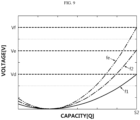
- FIG. 9 is a diagram schematically showing a conversion function (f1, f2) and a conversion prediction function (fe) derived by the battery management apparatus 100 according to an embodiment of the present disclosure.
- FIG. 8 is diagram showing the reference positive electrode profile (Pc), two positive electrode profiles (hereinafter, referred to as the second positive electrode profile (Pc2) and the third positive electrode profile (Pc3)) generated by the profile generating unit 120, and the positive electrode prediction profile (Pc_e) generated by the control unit 130.
- the second positive electrode profile (Pc2) may be a positive electrode profile generated by the profile generating unit 120 in the embodiment of FIG. 7 .
- FIG. 9 is a diagram showing the first conversion function (f1)between the reference positive electrode profile (Pc) and the second positive electrode profile (Pc2), the second conversion function (f2) between the reference positive electrode profile (Pc) and the third positive electrode profile (Pc3), and the conversion prediction function (fe) between the reference positive electrode profile (Pc) and the positive electrode prediction profile (Pc_e).
- the conversion prediction function (fe) may be derived based on the voltage change amount per capacity between the first conversion function (f1) and the second conversion function (f2).
- the positive electrode profile generated by the profile generating unit 120 at the 100 th cycle point is the second positive electrode profile (Pc2)
- the positive electrode profile generated at the 200 th cycle point is the third positive electrode profile (Pc3).
- the control unit 130 may derive the first conversion function (f1)capable of converting the reference positive electrode profile (Pc) into the second positive electrode profile (Pc2) by comparing the reference positive electrode profile (Pc) and the second positive electrode profile (Pc2).
- control unit 130 may derive the second conversion function (f2) capable of converting the reference positive electrode profile (Pc) into the third positive electrode profile (Pc3) by comparing the reference positive electrode profile (Pc) and the third positive electrode profile (Pc3).
- the first conversion function (f1) is a conversion function corresponding to the 100 th cycle point
- the second conversion function (f2) is a conversion function corresponding to the 200 th cycle point.
- control unit 130 may derive the conversion prediction function (fe) based on the voltage change rate per capacity between the first conversion function (f1) and the second conversion function (f2) in consideration of a cycle point corresponding to each of the first conversion function (f1) and the second conversion function (f2).
- the conversion prediction function (fe) derived by the control unit 130 may be a conversion function corresponding to the 300 th cycle point.
- the control unit 130 may derive the conversion prediction function (fe) in which the voltage corresponding to S2 [mAh] is Vf [V] by considering that the difference between the cycle point corresponding to the first conversion function (f1) and the cycle point corresponding to the second conversion function (f2) is 100 cycle points. In this way, the control unit 130 may derive the conversion prediction function (fe) by comparing the voltage per capacity of the first conversion function (f1) and the voltage per capacity of the second conversion function (f2) in the entire capacity region.
- control unit 130 may be configured to generate the positive electrode prediction profile (Pc_e) by applying the derived conversion prediction function (fe) to the reference positive electrode profile (Pc).
- control unit 130 may be configured to generate the positive electrode prediction profile (Pc_e) for the target point by deriving the conversion prediction function (fe) for the target point and applying the derived conversion prediction function (fe) to the reference positive electrode profile (Pc).
- control unit 130 may derive the conversion prediction function (fe) corresponding to the 300 th cycle point based on the first conversion function (f1) corresponding to the 100 th cycle point and the second conversion function (f2) corresponding to the 200 th cycle point.
- control unit 130 may generate the positive electrode prediction profile (Pc_e) corresponding to the 300 th cycle point by applying the conversion prediction function (fe) to the reference positive electrode profile (Pc).
- control unit 130 may be configured to generate the battery prediction profile (Pb_e) by calculating a difference between the voltage of the positive electrode prediction profile (Pc_e) and the voltage of the adjusted negative electrode profile for the same capacity.
- FIG. 10 is a diagram schematically showing an example where the battery prediction profile (Pb_e) is generated by the battery management apparatus 100 according to an embodiment of the present disclosure.
- the adjusted negative electrode profile (Pa3) of FIG. 10 may be a negative electrode profile corresponding to the third positive electrode profile (Pc3). That is, the adjusted negative electrode profile (Pa3) of FIG. 10 is a negative electrode profile generated by adjusting the offset and/or the scale of the reference negative electrode profile (Pa) in order for the profile generating unit 120 to generate the third positive electrode profile (Pc3).
- the voltage corresponding to the S3 [mAh] capacity in the adjusted negative electrode profile (Pa3) may be Vg [V]
- the voltage corresponding to the S3 [mAh] capacity in the positive electrode prediction profile (Pc_e) may be Vi [V].
- the control unit 130 may obtain Vh [V] by calculating "Vi - Vg”.
- the control unit 130 may generate a battery prediction profile (Pb_e) in which the voltage corresponding to the S3 [mAh] capacity is Vh [V].
- the control unit 130 may generate the battery prediction profile (Pb_e) corresponding to the 300 th cycle point based on the positive electrode prediction profile (Pc_e) corresponding to the 300 th cycle point and the adjusted negative electrode profile (Pa3) corresponding to the 200 th cycle point.
- the profile generating unit 120 generates a battery profile and a positive electrode profile at the 100 th cycle point and the 200 th cycle point has been described.
- the cycle in which the profile generating unit 120 generates the battery profile and the positive electrode profile may be adjusted.
- the profile generating unit 120 may generate a battery profile and a positive electrode profile at every 10 cycle points.
- control unit 130 may be configured to generate the battery prediction profile (Pb_e) by calculating the difference between the voltage of the positive electrode prediction profile (Pc_e) and the voltage of the reference negative electrode profile (Pa) for the same capacity.
- the control unit 130 may generate the battery prediction profile (Pb_e) based on the positive electrode prediction profile (Pc_e) and the reference negative electrode profile (Pa). That is, as described above, even if the battery cell B is degraded, the shape of the reference negative electrode profile (Pa) does not change significantly, so the control unit 130 may also generate the battery prediction profile (Pb_e), which further considers the degradation associated with the positive electrode of the battery cell B, based on the reference negative electrode profile (Pa).
- the profile generating unit 120 may be configured to generate the battery profile (Pb) and generate the positive electrode profile at every preset cycle.
- the profile generating unit 120 may generate a battery profile (Pb) and a positive electrode profile at every 100 cycle points.
- the second positive electrode profile (Pc2) may be a positive electrode profile generated at the 100 th cycle point
- the third positive electrode profile (Pc3) may be a positive electrode profile generated at the 200 th cycle point.
- control unit 130 may be configured to derive a conversion function between each of the plurality of positive electrode profiles (Pc2, Pc3) generated by the profile generating unit 120 until the current cycle and the reference positive electrode profile (Pc) and derive the conversion prediction function (fe) based on the plurality of derived conversion functions (f1, f2).
- the control unit 130 may derive a conversion function for the corresponding cycle point. For example, in the embodiment of FIG. 9 , the control unit 130 may derive the first conversion function (f1) corresponding to the second positive electrode profile (Pc2) generated at the 100 th cycle point. In addition, the control unit 130 may derive the second conversion function (f2) corresponding to the third positive electrode profile (Pc3) generated at the 200 th cycle point.
- control unit 130 may be configured to generate the battery prediction profile (Pb_e) after generating the positive electrode prediction profile (Pc_e) using the derived conversion prediction function (fe) and the reference positive electrode profile (Pc) until the next cycle arrives.
- the control unit 130 may generate a plurality of battery prediction profiles (Pb_e) by deriving the conversion prediction functions (fe) from the 201 st cycle point to the 299 th cycle point.
- the control unit 130 may generate the battery prediction profile (Pb_e) not only at the cycle point where the battery profile (Pb) and the positive electrode profile (Pc2, Pc3) are generated by the profile generating unit 120 but also at the time point until the next cycle arrives. Therefore, since the battery profile (Pb) or the battery prediction profile (Pb_e) at various cycle points may be obtained, the battery management apparatus 100 according to an embodiment of the present disclosure has an advantage of providing a profile by which the degradation of the battery cell B may be more specifically analyzed.
- the battery profile (Pb), the positive electrode profile (Pc2, Pc3), and the adjusted negative electrode profile (Pa2, Pa3) corresponding to each other may be provided, or the battery prediction profile (Pb_e), the positive electrode prediction profile (Pc_e), and the adjusted negative electrode profile (Pa2, Pa3) corresponding to each other may be provided.
- the profile (the battery profile (Pb) or the battery prediction profile (Pb_e)) for a full cell is provided as data for analyzing the degradation of the battery cell B, but also the profile (the positive electrode profile (Pc2, Pc3)) for the positive electrode half-cell or the profile (the adjusted negative electrode profile (Pa2, Pa3)) for the positive electrode prediction profile (Pc_e)) and the negative electrode half-cell profile may be provided together. Accordingly, it is possible to more precisely analyze not only whether the battery cell B is degraded, but also analyze the cause of degradation whether the degradation of the battery cell B is due to the degradation of the positive electrode or the degradation of the negative electrode.
- the battery management apparatus 100 may be applied to a BMS (Battery Management System). That is, the BMS according to the present disclosure may include the battery management apparatus 100. In this configuration, at least some of the components of the battery management apparatus 100 may be implemented by supplementing or adding functions of components included in a conventional BMS. For example, the measuring unit 110, the profile generating unit 120, the control unit 130 and the storage unit 140 of the battery management apparatus 100 may be implemented as components of the BMS.
- the battery management apparatus 100 may be provided to a battery pack 1. That is, the battery pack 1 according to the present disclosure may include the battery management apparatus 100 as described above and at least one battery cell B. In addition, the battery pack 1 may further include electrical equipment (relays, fuses, etc.), a case, and the like.
- the battery pack 1 may include a battery cell B and the battery management apparatus 100.
- a charging and discharging unit 2 may be connected to a positive electrode terminal (P+) and a negative electrode terminal (P-) of the battery pack 1 to charge or discharge the battery cell B.
- P+ positive electrode terminal
- P- negative electrode terminal
- all of the battery cell B, the battery management apparatus 100, and the charging and discharging unit 2 may be included in the battery pack 1.
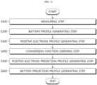
- FIG. 11 is a diagram schematically showing a battery management method according to another embodiment of the present disclosure.
- Each step of the battery management method according to another embodiment of the present disclosure may be performed by the battery management apparatus 100.
- the content overlapping with the previously described content will be omitted or briefly described.
- the battery management method may include a measuring step (S100), a battery profile generating step (S200), a positive electrode profile generating step (S300), a conversion function deriving step (S400), a positive electrode prediction profile generating step (S500), and a battery prediction profile generating step (S600).
- the measuring step (S100) is a step of measuring the voltage and capacity of the battery cell B, and may be performed by the measuring unit 110.
- the measuring unit 110 may measure the voltage of the battery cell B using the first sensing line SL1 and the second sensing line SL2. Also, the measuring unit 110 may measure the current of the battery cell B using the third sensing line SL3, and may measure the capacity of the battery cell B based on the measurement time and the measured current.
- the battery profile generating step (S200) is a step of generating a battery profile (Pb) representing the correspondence between the voltage and the capacity measured in the measuring step (S 100), and may be performed by the profile generating unit 120.
- the profile generating unit 120 may receive the voltage and the capacity of the battery cell B from the measuring unit 110, and generate a battery profile (Pb) representing the correspondence between the voltage and the capacity corresponding to each other.
- the positive electrode profile generating step (S300) is a step of generating a positive electrode profile of the battery cell B based on the battery profile (Pb) generated in the battery profile generating step (S200) as well as a reference negative electrode profile (Pa) and a reference negative electrode differential profile (Pa_d) preset for the battery cell B, and may be performed by the profile generating unit 120.
- the profile generating unit 120 may convert the battery profile (Pb) into a battery differential profile (Pb_d).In addition, the profile generating unit 120 may adjust the reference negative electrode differential profile (Pa_d) to correspond to the battery differential profile (Pb_d). In addition, the profile generating unit 120 may adjust the reference negative electrode profile (Pa) to correspond to the adjusted negative electrode differential profile (Pa_d2). Finally, the profile generating unit 120 may generate a positive electrode profile based on the adjusted negative electrode profile (Pa2) and the battery profile (Pb).
- the profile generating unit 120 may generate a positive electrode profile by summing the voltage per capacity of the generated battery profile (Pb) and the voltage per capacity of the adjusted negative electrode profile (Pa2).
- the conversion function deriving step (S400) is a step of deriving a conversion function representing conversion information from the reference positive electrode profile (Pc) preset for the battery cell B to the generated positive electrode profile, and may be performed by the control unit 130.
- the positive electrode profile generated by the profile generating unit 120 may be derived.
- the reference positive electrode profile (Pc) may be derived.
- the positive electrode prediction profile generating step (S500) is a step of generating a positive electrode prediction profile (Pc_e) for the battery cell B from the reference positive electrode profile (Pc) based on the conversion function derived in the conversion function deriving step (S400), and may be performed by the control unit 130.
- control unit 130 may include a plurality of conversion functions, and may derive a conversion prediction function (fe) based on the voltage change per capacity of the plurality of provided conversion functions.
- control unit 130 may generate the positive electrode prediction profile (Pc_e) by applying the derived conversion prediction function (fe) to the reference positive electrode profile (Pc).
- the battery prediction profile generating step (S600) is a step of generating a battery prediction profile (Pb_e) for the battery cell B based on the positive electrode prediction profile (Pc_e) generated in the positive electrode prediction profile generating step (S500), and may be performed by the control unit 130.
- the control unit 130 may generate a battery prediction profile (Pb_e) based on the positive electrode prediction profile (Pc_e) and the adjusted negative electrode profile (Pa2).
- the control unit 130 may generate a battery prediction profile (Pb_e) based on the positive electrode prediction profile (Pc_e) and the reference negative electrode profile (Pa).
- the battery prediction profile (Pb_e) may be generated based on the positive electrode prediction profile (Pc_e) and the adjusted negative electrode profile (Pa2).
- the embodiments of the present disclosure described above may not be implemented only through an apparatus and a method, but may be implemented through a program that realizes a function corresponding to the configuration of the embodiments of the present disclosure or a recording medium on which the program is recorded.
- the program or recording medium may be easily implemented by those skilled in the art from the above description of the embodiments.
Landscapes
- Physics & Mathematics (AREA)
- General Physics & Mathematics (AREA)
- Engineering & Computer Science (AREA)
- Manufacturing & Machinery (AREA)
- Chemical & Material Sciences (AREA)
- Chemical Kinetics & Catalysis (AREA)
- Electrochemistry (AREA)
- General Chemical & Material Sciences (AREA)
- Microelectronics & Electronic Packaging (AREA)
- Secondary Cells (AREA)
- Tests Of Electric Status Of Batteries (AREA)
Applications Claiming Priority (2)
| Application Number | Priority Date | Filing Date | Title |
|---|---|---|---|
| KR1020200113290A KR102846753B1 (ko) | 2020-09-04 | 2020-09-04 | 배터리 관리 장치 및 방법 |
| PCT/KR2021/007913 WO2022050540A1 (fr) | 2020-09-04 | 2021-06-23 | Dispositif et procédé de gestion de batterie |
Publications (3)
| Publication Number | Publication Date |
|---|---|
| EP4135099A1 true EP4135099A1 (fr) | 2023-02-15 |
| EP4135099A4 EP4135099A4 (fr) | 2023-11-22 |
| EP4135099B1 EP4135099B1 (fr) | 2026-03-18 |
Family
ID=80491298
Family Applications (1)
| Application Number | Title | Priority Date | Filing Date |
|---|---|---|---|
| EP21864503.4A Active EP4135099B1 (fr) | 2020-09-04 | 2021-06-23 | Appareil et procédé de gestion de batterie |
Country Status (5)
| Country | Link |
|---|---|
| EP (1) | EP4135099B1 (fr) |
| JP (1) | JP7409597B2 (fr) |
| KR (1) | KR102846753B1 (fr) |
| CN (1) | CN115516695B (fr) |
| WO (1) | WO2022050540A1 (fr) |
Cited By (1)
| Publication number | Priority date | Publication date | Assignee | Title |
|---|---|---|---|---|
| EP4556925A4 (fr) * | 2022-12-26 | 2026-03-04 | Lg Energy Solution Ltd | Appareil et procédé de gestion de batterie |
Families Citing this family (15)
| Publication number | Priority date | Publication date | Assignee | Title |
|---|---|---|---|---|
| KR102672284B1 (ko) | 2022-06-21 | 2024-06-03 | 주식회사 엘지에너지솔루션 | 배터리 관리 장치 및 방법 |
| JP7729322B2 (ja) * | 2022-12-12 | 2025-08-26 | 株式会社デンソー | 残容量算出装置及びプログラム |
| EP4553523A4 (fr) | 2022-12-26 | 2026-03-04 | Lg Energy Solution Ltd | Appareil et procédé de gestion de batterie |
| JP2026500698A (ja) * | 2022-12-26 | 2026-01-08 | エルジー エナジー ソリューション リミテッド | バッテリー管理装置及び方法 |
| WO2024144229A2 (fr) * | 2022-12-26 | 2024-07-04 | 주식회사 엘지에너지솔루션 | Appareil et procédé de gestion de batterie |
| EP4641749A4 (fr) * | 2022-12-26 | 2026-03-04 | Lg Energy Solution Ltd | Appareil et procédé de gestion de batterie |
| KR102813498B1 (ko) * | 2022-12-26 | 2025-05-28 | 주식회사 엘지에너지솔루션 | 배터리 관리 장치 및 방법 |
| JP7769841B1 (ja) | 2022-12-28 | 2025-11-13 | エルジー エナジー ソリューション リミテッド | バッテリー管理装置及び方法 |
| KR20250017041A (ko) * | 2023-07-26 | 2025-02-04 | 주식회사 엘지에너지솔루션 | 배터리 관리 장치 및 방법 |
| KR20250106953A (ko) | 2024-01-04 | 2025-07-11 | 주식회사 엘지에너지솔루션 | 배터리 관리 장치 및 방법 |
| WO2025150978A1 (fr) * | 2024-01-12 | 2025-07-17 | 주식회사 엘지에너지솔루션 | Appareil de gestion de batterie et procédé associé |
| CN120936892A (zh) * | 2024-01-12 | 2025-11-11 | 株式会社Lg新能源 | 电池管理装置及其方法 |
| KR20250117109A (ko) * | 2024-01-26 | 2025-08-04 | 주식회사 엘지에너지솔루션 | 배터리 정보 생성 장치 및 방법 |
| KR102825235B1 (ko) * | 2024-01-26 | 2025-06-24 | 주식회사 엘지에너지솔루션 | 배터리 정보 생성 장치 및 방법 |
| KR102766452B1 (ko) * | 2024-02-16 | 2025-02-10 | 주식회사 엘지에너지솔루션 | 배터리 진단 장치 및 방법 |
Family Cites Families (17)
| Publication number | Priority date | Publication date | Assignee | Title |
|---|---|---|---|---|
| US9130248B2 (en) * | 2012-05-25 | 2015-09-08 | GM Global Technology Operations LLC | Modeling changes in the state-of-charge open circuit voltage curve by using regressed parameters in a reduced order physics based model |
| EP2990818B1 (fr) * | 2014-09-01 | 2019-11-27 | Yokogawa Electric Corporation | Système et procédé de mesure de capacité de batterie secondaire |
| JP6123844B2 (ja) * | 2014-09-01 | 2017-05-10 | 横河電機株式会社 | 二次電池容量測定システム及び二次電池容量測定方法 |
| KR101696313B1 (ko) * | 2014-10-24 | 2017-01-13 | 주식회사 엘지화학 | 이차전지의 퇴화에 따른 soc-ocv 프로파일 추정 방법 |
| DE102015214128A1 (de) * | 2015-07-27 | 2017-02-02 | Robert Bosch Gmbh | Verfahren und Vorrichtung zum Abschätzen eines aktuellen Leerlaufspannungsverlaufs einer Batterie |
| KR102574084B1 (ko) * | 2016-01-14 | 2023-09-04 | 삼성전자주식회사 | 배터리 관리 장치 및 방법 |
| MX2018011648A (es) | 2016-03-31 | 2019-01-30 | Omeros Corp | Metodos para la inhibicion de fibrosis en un sujeto en necesidad del mismo. |
| JP6477610B2 (ja) | 2016-06-22 | 2019-03-06 | 横河電機株式会社 | 二次電池容量測定システムおよび二次電池容量測定方法 |
| CN106127793B (zh) * | 2016-07-29 | 2019-07-09 | 广东正业科技股份有限公司 | 一种电池阴阳电极轮廓的提取方法 |
| KR101972521B1 (ko) * | 2016-08-26 | 2019-04-25 | 주식회사 엘지화학 | 배터리 셀의 성능 테스트 장치 및 방법 |
| KR102730913B1 (ko) * | 2017-02-07 | 2024-11-14 | 삼성전자주식회사 | 배터리 충전 방법 및 장치 |
| JP7069593B2 (ja) * | 2017-08-09 | 2022-05-18 | 株式会社デンソー | 電池状態推定装置及び電源装置 |
| KR102258833B1 (ko) * | 2017-09-28 | 2021-05-31 | 주식회사 엘지에너지솔루션 | 리튬 이온 배터리 셀의 퇴화 정보를 획득하는 장치 |
| KR102563753B1 (ko) * | 2017-12-29 | 2023-08-04 | 삼성전자주식회사 | 배터리 충전 방법 및 장치 |
| KR102156404B1 (ko) * | 2018-01-09 | 2020-09-15 | 주식회사 엘지화학 | 배터리 셀 성능 테스트 장치 및 방법 |
| KR102452626B1 (ko) * | 2018-03-07 | 2022-10-06 | 주식회사 엘지에너지솔루션 | Soc-ocv 프로파일 추정 방법 및 장치 |
| EP3703177B1 (fr) * | 2018-08-09 | 2023-01-04 | LG Energy Solution, Ltd. | Procédé d'analyse précise du degré d'imprégnation d'électrolyte d'électrode dans une cellule |
-
2020
- 2020-09-04 KR KR1020200113290A patent/KR102846753B1/ko active Active
-
2021
- 2021-06-23 JP JP2022567642A patent/JP7409597B2/ja active Active
- 2021-06-23 WO PCT/KR2021/007913 patent/WO2022050540A1/fr not_active Ceased
- 2021-06-23 EP EP21864503.4A patent/EP4135099B1/fr active Active
- 2021-06-23 CN CN202180029481.7A patent/CN115516695B/zh active Active
Cited By (1)
| Publication number | Priority date | Publication date | Assignee | Title |
|---|---|---|---|---|
| EP4556925A4 (fr) * | 2022-12-26 | 2026-03-04 | Lg Energy Solution Ltd | Appareil et procédé de gestion de batterie |
Also Published As
| Publication number | Publication date |
|---|---|
| KR20220031412A (ko) | 2022-03-11 |
| EP4135099B1 (fr) | 2026-03-18 |
| EP4135099A4 (fr) | 2023-11-22 |
| CN115516695B (zh) | 2025-08-01 |
| WO2022050540A1 (fr) | 2022-03-10 |
| JP7409597B2 (ja) | 2024-01-09 |
| JP2023524580A (ja) | 2023-06-12 |
| KR102846753B1 (ko) | 2025-08-13 |
| US20230318057A1 (en) | 2023-10-05 |
| CN115516695A (zh) | 2022-12-23 |
Similar Documents
| Publication | Publication Date | Title |
|---|---|---|
| EP4135099B1 (fr) | Appareil et procédé de gestion de batterie | |
| US11990590B2 (en) | Battery management apparatus and method | |
| US20250389775A1 (en) | Battery Management Apparatus and Method | |
| EP4163655B1 (fr) | Appareil et procédé de gestion de batterie | |
| EP4155748A1 (fr) | Dispositif et procédé de gestion de batteries | |
| EP4145158B1 (fr) | Dispositif et procédé de diagnostic de batterie | |
| US12388282B2 (en) | Battery management apparatus and method | |
| EP3998489B1 (fr) | Dispositif et procédé de diagnostic dod pour batterie | |
| EP4145589A1 (fr) | Dispositif et procédé de classification de batterie | |
| CN115667957B (zh) | 电池管理设备、电池检测装置及电池管理方法 | |
| EP4152025A1 (fr) | Dispositif et procédé de diagnostic de batterie | |
| EP4641749A2 (fr) | Appareil et procédé de gestion de batterie | |
| US12620641B2 (en) | Battery management apparatus and method | |
| EP4191747A1 (fr) | Appareil et procédé de détection de précipitation de lithium |
Legal Events
| Date | Code | Title | Description |
|---|---|---|---|
| STAA | Information on the status of an ep patent application or granted ep patent |
Free format text: STATUS: THE INTERNATIONAL PUBLICATION HAS BEEN MADE |
|
| PUAI | Public reference made under article 153(3) epc to a published international application that has entered the european phase |
Free format text: ORIGINAL CODE: 0009012 |
|
| STAA | Information on the status of an ep patent application or granted ep patent |
Free format text: STATUS: REQUEST FOR EXAMINATION WAS MADE |
|
| 17P | Request for examination filed |
Effective date: 20221111 |
|
| AK | Designated contracting states |
Kind code of ref document: A1 Designated state(s): AL AT BE BG CH CY CZ DE DK EE ES FI FR GB GR HR HU IE IS IT LI LT LU LV MC MK MT NL NO PL PT RO RS SE SI SK SM TR |
|
| A4 | Supplementary search report drawn up and despatched |
Effective date: 20231024 |
|
| RIC1 | Information provided on ipc code assigned before grant |
Ipc: H01M 10/44 20060101ALI20231018BHEP Ipc: H01M 10/42 20060101ALI20231018BHEP Ipc: G01R 31/392 20190101ALI20231018BHEP Ipc: G01R 31/388 20190101ALI20231018BHEP Ipc: G01R 31/36 20200101ALI20231018BHEP Ipc: H01M 10/48 20060101AFI20231018BHEP |
|
| DAV | Request for validation of the european patent (deleted) | ||
| DAX | Request for extension of the european patent (deleted) | ||
| GRAP | Despatch of communication of intention to grant a patent |
Free format text: ORIGINAL CODE: EPIDOSNIGR1 |
|
| STAA | Information on the status of an ep patent application or granted ep patent |
Free format text: STATUS: GRANT OF PATENT IS INTENDED |
|
| INTG | Intention to grant announced |
Effective date: 20251015 |
|
| P01 | Opt-out of the competence of the unified patent court (upc) registered |
Free format text: CASE NUMBER: UPC_APP_0012149_4135099/2025 Effective date: 20251105 |
|
| GRAS | Grant fee paid |
Free format text: ORIGINAL CODE: EPIDOSNIGR3 |
|
| GRAA | (expected) grant |
Free format text: ORIGINAL CODE: 0009210 |
|
| STAA | Information on the status of an ep patent application or granted ep patent |
Free format text: STATUS: THE PATENT HAS BEEN GRANTED |
|
| AK | Designated contracting states |
Kind code of ref document: B1 Designated state(s): AL AT BE BG CH CY CZ DE DK EE ES FI FR GB GR HR HU IE IS IT LI LT LU LV MC MK MT NL NO PL PT RO RS SE SI SK SM TR |
|
| REG | Reference to a national code |
Ref country code: CH Ref legal event code: F10 Free format text: ST27 STATUS EVENT CODE: U-0-0-F10-F00 (AS PROVIDED BY THE NATIONAL OFFICE) Effective date: 20260318 Ref country code: GB Ref legal event code: FG4D |
|
| REG | Reference to a national code |
Ref country code: DE Ref legal event code: R096 Ref document number: 602021050337 Country of ref document: DE |
|
| REG | Reference to a national code |
Ref country code: IE Ref legal event code: FG4D |