EP4135149A1 - Ladesteuerungsverfahren und -vorrichtung, batterieverwaltungssystem und lesbares speichermedium - Google Patents
Ladesteuerungsverfahren und -vorrichtung, batterieverwaltungssystem und lesbares speichermedium Download PDFInfo
- Publication number
- EP4135149A1 EP4135149A1 EP21819319.1A EP21819319A EP4135149A1 EP 4135149 A1 EP4135149 A1 EP 4135149A1 EP 21819319 A EP21819319 A EP 21819319A EP 4135149 A1 EP4135149 A1 EP 4135149A1
- Authority
- EP
- European Patent Office
- Prior art keywords
- charging
- battery
- waveform
- pulse
- frequency
- Prior art date
- Legal status (The legal status is an assumption and is not a legal conclusion. Google has not performed a legal analysis and makes no representation as to the accuracy of the status listed.)
- Granted
Links
Images


Classifications
-
- H—ELECTRICITY
- H02—GENERATION; CONVERSION OR DISTRIBUTION OF ELECTRIC POWER
- H02J—ELECTRIC POWER NETWORKS; CIRCUIT ARRANGEMENTS OR SYSTEMS FOR SUPPLYING OR DISTRIBUTING ELECTRIC POWER; SYSTEMS FOR STORING ELECTRIC ENERGY
- H02J7/00—Circuit arrangements for charging or discharging batteries or for supplying loads from batteries
- H02J7/90—Regulation of charging or discharging current or voltage
- H02J7/927—Regulation of charging or discharging current or voltage with introduction of pulses during the charging process
-
- G—PHYSICS
- G01—MEASURING; TESTING
- G01R—MEASURING ELECTRIC VARIABLES; MEASURING MAGNETIC VARIABLES
- G01R31/00—Arrangements for testing electric properties; Arrangements for locating electric faults; Arrangements for electrical testing characterised by what is being tested not provided for elsewhere
- G01R31/36—Arrangements for testing, measuring or monitoring the electrical condition of accumulators or electric batteries, e.g. capacity or state of charge [SoC]
- G01R31/382—Arrangements for monitoring battery or accumulator variables, e.g. SoC
-
- H—ELECTRICITY
- H01—ELECTRIC ELEMENTS
- H01M—PROCESSES OR MEANS, e.g. BATTERIES, FOR THE DIRECT CONVERSION OF CHEMICAL ENERGY INTO ELECTRICAL ENERGY
- H01M10/00—Secondary cells; Manufacture thereof
- H01M10/42—Methods or arrangements for servicing or maintenance of secondary cells or secondary half-cells
- H01M10/425—Structural combination with electronic components, e.g. electronic circuits integrated to the outside of the casing
-
- H—ELECTRICITY
- H01—ELECTRIC ELEMENTS
- H01M—PROCESSES OR MEANS, e.g. BATTERIES, FOR THE DIRECT CONVERSION OF CHEMICAL ENERGY INTO ELECTRICAL ENERGY
- H01M10/00—Secondary cells; Manufacture thereof
- H01M10/42—Methods or arrangements for servicing or maintenance of secondary cells or secondary half-cells
- H01M10/44—Methods for charging or discharging
- H01M10/443—Methods for charging or discharging in response to temperature
-
- H—ELECTRICITY
- H01—ELECTRIC ELEMENTS
- H01M—PROCESSES OR MEANS, e.g. BATTERIES, FOR THE DIRECT CONVERSION OF CHEMICAL ENERGY INTO ELECTRICAL ENERGY
- H01M10/00—Secondary cells; Manufacture thereof
- H01M10/42—Methods or arrangements for servicing or maintenance of secondary cells or secondary half-cells
- H01M10/48—Accumulators combined with arrangements for measuring, testing or indicating the condition of cells, e.g. the level or density of the electrolyte
- H01M10/486—Accumulators combined with arrangements for measuring, testing or indicating the condition of cells, e.g. the level or density of the electrolyte for measuring temperature
-
- H—ELECTRICITY
- H02—GENERATION; CONVERSION OR DISTRIBUTION OF ELECTRIC POWER
- H02J—ELECTRIC POWER NETWORKS; CIRCUIT ARRANGEMENTS OR SYSTEMS FOR SUPPLYING OR DISTRIBUTING ELECTRIC POWER; SYSTEMS FOR STORING ELECTRIC ENERGY
- H02J7/00—Circuit arrangements for charging or discharging batteries or for supplying loads from batteries
- H02J7/40—Circuit arrangements for charging or discharging batteries or for supplying loads from batteries characterised by the exchange of charge or discharge related data
-
- H—ELECTRICITY
- H02—GENERATION; CONVERSION OR DISTRIBUTION OF ELECTRIC POWER
- H02J—ELECTRIC POWER NETWORKS; CIRCUIT ARRANGEMENTS OR SYSTEMS FOR SUPPLYING OR DISTRIBUTING ELECTRIC POWER; SYSTEMS FOR STORING ELECTRIC ENERGY
- H02J7/00—Circuit arrangements for charging or discharging batteries or for supplying loads from batteries
- H02J7/80—Circuit arrangements for charging or discharging batteries or for supplying loads from batteries including monitoring or indicating arrangements
- H02J7/82—Control of state of charge [SOC]
-
- H—ELECTRICITY
- H02—GENERATION; CONVERSION OR DISTRIBUTION OF ELECTRIC POWER
- H02J—ELECTRIC POWER NETWORKS; CIRCUIT ARRANGEMENTS OR SYSTEMS FOR SUPPLYING OR DISTRIBUTING ELECTRIC POWER; SYSTEMS FOR STORING ELECTRIC ENERGY
- H02J7/00—Circuit arrangements for charging or discharging batteries or for supplying loads from batteries
- H02J7/875—Charging or discharging for charge maintenance, battery initiation or rejuvenation
-
- H—ELECTRICITY
- H02—GENERATION; CONVERSION OR DISTRIBUTION OF ELECTRIC POWER
- H02J—ELECTRIC POWER NETWORKS; CIRCUIT ARRANGEMENTS OR SYSTEMS FOR SUPPLYING OR DISTRIBUTING ELECTRIC POWER; SYSTEMS FOR STORING ELECTRIC ENERGY
- H02J7/00—Circuit arrangements for charging or discharging batteries or for supplying loads from batteries
- H02J7/90—Regulation of charging or discharging current or voltage
- H02J7/96—Regulation of charging or discharging current or voltage in response to battery voltage
- H02J7/963—Regulation of charging or discharging current or voltage in response to battery voltage in response to battery voltage gradient
-
- H—ELECTRICITY
- H02—GENERATION; CONVERSION OR DISTRIBUTION OF ELECTRIC POWER
- H02J—ELECTRIC POWER NETWORKS; CIRCUIT ARRANGEMENTS OR SYSTEMS FOR SUPPLYING OR DISTRIBUTING ELECTRIC POWER; SYSTEMS FOR STORING ELECTRIC ENERGY
- H02J7/00—Circuit arrangements for charging or discharging batteries or for supplying loads from batteries
- H02J7/90—Regulation of charging or discharging current or voltage
- H02J7/971—Regulation of charging or discharging current or voltage the charge cycle being controlled or terminated in response to non-electric parameters
- H02J7/975—Regulation of charging or discharging current or voltage the charge cycle being controlled or terminated in response to non-electric parameters in response to temperature
- H02J7/977—Regulation of charging or discharging current or voltage the charge cycle being controlled or terminated in response to non-electric parameters in response to temperature of the battery
-
- H—ELECTRICITY
- H01—ELECTRIC ELEMENTS
- H01M—PROCESSES OR MEANS, e.g. BATTERIES, FOR THE DIRECT CONVERSION OF CHEMICAL ENERGY INTO ELECTRICAL ENERGY
- H01M10/00—Secondary cells; Manufacture thereof
- H01M10/42—Methods or arrangements for servicing or maintenance of secondary cells or secondary half-cells
- H01M10/44—Methods for charging or discharging
- H01M10/446—Initial charging measures
-
- H—ELECTRICITY
- H02—GENERATION; CONVERSION OR DISTRIBUTION OF ELECTRIC POWER
- H02J—ELECTRIC POWER NETWORKS; CIRCUIT ARRANGEMENTS OR SYSTEMS FOR SUPPLYING OR DISTRIBUTING ELECTRIC POWER; SYSTEMS FOR STORING ELECTRIC ENERGY
- H02J7/00—Circuit arrangements for charging or discharging batteries or for supplying loads from batteries
- H02J7/90—Regulation of charging or discharging current or voltage
- H02J7/92—Regulation of charging or discharging current or voltage with prioritisation of loads or sources
-
- Y—GENERAL TAGGING OF NEW TECHNOLOGICAL DEVELOPMENTS; GENERAL TAGGING OF CROSS-SECTIONAL TECHNOLOGIES SPANNING OVER SEVERAL SECTIONS OF THE IPC; TECHNICAL SUBJECTS COVERED BY FORMER USPC CROSS-REFERENCE ART COLLECTIONS [XRACs] AND DIGESTS
- Y02—TECHNOLOGIES OR APPLICATIONS FOR MITIGATION OR ADAPTATION AGAINST CLIMATE CHANGE
- Y02E—REDUCTION OF GREENHOUSE GAS [GHG] EMISSIONS, RELATED TO ENERGY GENERATION, TRANSMISSION OR DISTRIBUTION
- Y02E60/00—Enabling technologies; Technologies with a potential or indirect contribution to GHG emissions mitigation
- Y02E60/10—Energy storage using batteries
Definitions
- the present application relates to the technical field of batteries, and in particular, relates to a charging control method and apparatus, a battery management system and a readable storage medium.
- Pulse charging is a battery charging technique for charging a battery with a pulse current.
- a bidirectional pulse current is generally employed to charge the battery and a pulse charging frequency will be set as a battery characteristic frequency.
- the battery characteristic frequency changes with a change in a battery temperature and the pulse charging frequency is adjusted according to the battery characteristic frequency until the end of the charging.
- the objective of the present application is to provide a charging control method and apparatus, a battery management system and a readable storage medium for improving the stability and safety of the battery charging.
- the present application provides a charging control method, including: obtaining a battery temperature and a battery state of charge; determining a pulse charging frequency according to the battery temperature, the battery state of charge and a pre-calibrated corresponding relationship, where the pre-calibrated corresponding relationship is a corresponding relationship between a battery temperature, a battery state of charge, and a pulse charging frequency; obtaining a preset waveform characteristic of a pulse charging waveform, where the waveform characteristic includes a ratio range of an area of a positive pulse waveform to an area of a negative pulse waveform in each pulse cycle of the pulse charging waveform; generating a charging request according to the pulse charging frequency and the waveform characteristic; and transmitting the charging request to a charging device.
- the corresponding relationship between the pre-calibrated battery temperature, the state of charge and the pulse charging frequency is pre-calibrated, when a battery management system performs charging control, a real time battery temperature and state of charge are firstly obtained, and then based on the obtained battery temperature, the state of charge and the corresponding relationship, the pulse charging frequency is determined, thereby realizing effective determination of the pulse charging frequency.
- a waveform characteristic of a pulse charging waveform is preset, the waveform characteristic including a ratio range of an area of a positive pulse waveform to an area of a negative pulse waveform in each pulse cycle of the pulse charging waveform. Normal performing of the pulse charging can be ensured by setting the lower limit of the ratio range.
- the waveform characteristic further includes a preset current peak of the positive pulse waveform corresponding to the battery temperature and the state of charge, and a preset current peak of the negative pulse waveform corresponding to the battery temperature and the state of charge, and a current peak of the negative pulse waveform is greater than a current peak of the positive pulse waveform.
- the current peak of the negative pulse waveform in a pulse cycle, if the current peak of the negative pulse waveform is greater than the current peak of the positive pulse waveform, the current peak increases after switching from positive pulse charging to negative pulse charging, in which case it is not easy to cause lithium plating and cell polarization for the battery. Therefore, by defining the current peak of the negative pulse waveform to be greater than the current peak of the positive pulse waveform in the waveform characteristic, safety of the pulse charging can be improved, and the impact on battery performance can be avoided.
- the waveform characteristic further includes a positive pulse waveform characteristic; and the positive pulse waveform characteristic is represented as ⁇ t 1 t 2 F t ⁇ I max + ⁇ t 2 ⁇ t 1 2 ; where F ( t ) represents the positive pulse waveform, ⁇ t 1 t 2 F t is the area of the positive pulse waveform, t1 is a starting time of the positive pulse waveform, t2 is an ending time of the positive pulse waveform and I max+ is a current peak of the positive pulse waveform.
- the positive pulse waveform characteristic can be understood as that the area of the positive pulse waveform is greater than half of the area of a rectangular region corresponding to the positive pulse waveform.
- the pulse charging can be ensured to realize a maximum discharging current.
- a battery voltage corresponding to the current peak of the positive pulse waveform is smaller than a pre-calibrated charging cutoff voltage, and the charging cutoff voltage is a decomposition voltage of a battery electrolyte or a breakdown voltage value of a battery separator.
- the battery voltage corresponding to the current peak of the positive pulse waveform is an upper limit of the voltage, and the upper limit of the voltage can be limited through a charging cutoff voltage.
- the charging cutoff voltage is a decomposition voltage of a battery electrolyte or a breakdown voltage value of a battery separator.
- the two voltages are greater than a conventional charging cutoff voltage and the corresponding peak charging current is also larger. Therefore, by determining the two voltages as the voltage upper limit, the peak value of charging current can be increased to enable completion of charging for the battery as soon as possible, thus improving the charging efficiency of the battery.
- a frequency range of the pulse charging frequency in the pre-calibrated corresponding relationship is: 200Hz - 1500Hz.
- the frequency is smaller than 200Hz, it will be easy to cause lithium plating for the battery, thus causing attenuation of a capacity thereof. 1500Hz can be understood as the maximum frequency that the charging device can reach. Therefore, by defining the frequency range, smooth completion of charging can be ensured for the charging device while ensuring security of battery charging and preventing effects on battery performance.
- the charging control method before the determining a pulse charging frequency according to the battery temperature, the battery state of charge and a pre-calibrated corresponding relationship, the charging control method further includes: determining whether the battery temperature is in a preset temperature range; and the determining a pulse charging frequency according to the battery temperature, the battery state of charge and a pre-calibrated corresponding relationship includes: when determining that the battery temperature is in the preset temperature range, determining the pulse charging frequency according to the battery temperature, the battery state of charge and the pre-calibrated corresponding relationship.
- the battery management system controls the battery to perform pulse charging, equivalent to that the charging control policy of the battery can be flexibly adjusted according to a temperature situation to improve charging flexibility of the battery.
- an upper limit of the ratio range is 10 and a lower limit of the ratio range is 1.
- the lower limit of the ratio range is 1, in which case normal performing of the pulse charging can be ensured; and the upper limit of the ratio range is 10, in which case potential safety hazards caused by lithium plating of the battery due to excessively large positive pulse can be avoided.
- the present application provides a charging control apparatus, including each functional module for realizing the charging control method in the first aspect and any possible implementation of the first aspect.
- the present application provides a battery management system, including a processor and a memory communicatively connected with the processor, where the memory stores an instruction executable by the processor, and the instruction is executed by the processor to cause the processor to perform the charging control method in the first aspect and any possible implementation of the first aspect.
- the present application provides a readable storage medium, where a computer program is stored on the readable storage medium, and when the computer program is operated by a computer, the charging control method in the first aspect and any possible implementation of the first aspect is performed.
- REFERENCE SIGNS 10-charging system; 11-charging device; 12-battery management system; 120-processor; 121-memory; 122-communication module; 500-charging control apparatus; 510-obtaining module; and 520-processing module.
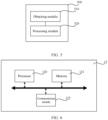
- FIG. 1 shows a schematic diagram of a charging system 10 provided by embodiment of the present application.
- the charging system 10 includes a charging device 11, a battery management system 12 and a battery.
- the charging device 11 and the battery management system 12 are in a communication connection
- the charging device 11 and the battery are in an electrical connection
- the battery management system 12 and the battery are in an electrical connection.
- the charging device 11 can be a charging pile, a charging box, a charging cabinet or the like. Within the charging device 11, a DC charging module and a pulse charging module can be included, i.e. the charging device 11 can realize DC charging and can also realize pulse charging.
- the battery management system 12 is used for managing the battery, such as management for various parameters like a SOC (state of charge) of the battery, a capacity of the battery and a temperature of the battery; and for performing charging control on the battery for example again. Therefore, a hardware environment to which the charging control method provided by embodiment of the present application is applied can be the battery management system 12 corresponding to the battery.
- the hardware environment in which a battery system formed by the battery management system 12 and the battery is located can be an electric device such as an electric that uses a power battery as a power source.
- the electric vehicle can be for example an electric automobile, an electric motor and the like. Therefore, the charging control method provided by embodiment of the present application can be applied to various electric devices.
- the battery can be various types of lithium batteries, for example, a lithium iron phosphate battery and a lithium iron sulfide battery etc.
- a charging message can interact between the charging device 11 and the battery management system 12.
- the battery management system 12 transmits corresponding charging information to the charging device 11 in a form of the charging message, and the charging device 11 charges the battery based on the obtained charging information in the charging message.
- a charging message can interact between the battery management system 12 and the charging device 11.
- the interaction of the charging message can be performed continuously between the battery management system 12 and the charging device 11.
- the charging information can be adjusted and the charging policy of the battery can also be adjusted. For example, the frequency of the pulse charging can be adjusted and the waveform of the pulse charging can be adjusted etc.
- FIG. 2 shows a flowchart of a charging control method provided by embodiment of the present application.
- the method can be applied to the battery management system 12, including:
- the corresponding relationship between the pre-calibrated battery temperature, the battery SOC and the pulse charging frequency is pre-calibrated, when a battery management system 12 performs charging control, a real time battery temperature and battery SOC are firstly obtained, and then based on the obtained battery temperature, battery SOC and the corresponding relationship, the pulse charging frequency is determined, thereby realizing effective determination of the pulse charging frequency.
- a waveform characteristic of a pulse charging waveform is preset, the waveform characteristic including a ratio range of an area of a positive pulse waveform to an area of a negative pulse waveform in each pulse cycle of the pulse charging waveform.
- the battery management system 12 can collect the battery temperature through a temperature collection module in a collection module of the charging information, realizing obtaining of the battery temperature.
- the temperature collection module can be a thermistor, a temperature sensor or the like.
- the battery management system 12 can also collect a voltage, a current, a power and other information of the battery through a voltage collection module, a current collection module, a power collection module and other collection modules of the collection module. Based on related information collected, the SOC of the battery is estimated, realizing obtaining of the SOC of the battery.
- the battery state information includes a battery temperature, a battery SOC, a voltage and a current etc. Accordingly, for the battery management system 12, in addition to obtaining the battery temperature and the battery SOC, can also obtain other battery state information when needed, such as a voltage, a current and the like of the battery.
- step 220 the corresponding relationship between the battery temperature, the battery SOC and the pulse charging frequency can be calibrated offline.
- the implementation of the offline calibration is introduced.
- the relationship between the cell impedance and the frequency can be represented through a cell impedance-frequency curve (profile).
- the abscissa of the curve is the frequency of an AC signal and the ordinate of the curve is an AC impedance of a cell anode, which is divided into an impedance real part and an impedance imaginary part.
- the process for determining a corresponding relationship between the frequency and the temperature includes: drawing a plurality of curves of the real part and the imaginary part for one same cell under different temperature conditions and different cell capacities, to obtain the curve functions of the real part and the imaginary part respectively. Then, one derivative is performed on the curve functions. When the derivative is negative and the derivative is smaller than a preset threshold for the first time, the frequency (abscissa value) corresponding to the derivative is a minimum value of the pulse charging frequency.
- the corresponding pulse current frequencies can also be obtained respectively for different SOC ranges, thus obtaining the pulse charging frequencies of different SOC ranges under the same temperature condition.
- the pulse charging frequency when calibrating the corresponding relationship, can also be limited in a fixed frequency range.
- the lower limit of the frequency in the fixed frequency range can be set according to the frequency value at which the effective values of the impedance real part and the impedance imaginary part start to decrease greatly.
- the lower limit for the frequency of the frequency range corresponding to the cell can be a frequency value which is slightly greater than 195Hz, such as 200Hz.
- the battery capacity will correspondingly decrease in case of lithium plating occurring to the battery. Therefore, in addition to the above implementation, a conventional battery charging and discharging capacity test can also be performed at a normal temperature. When the battery capacity decreases compared with the normal battery capacity, the corresponding frequency value can be determined as the frequency lower limit of the frequency range.
- the charging device 11 As the generator of the pulse current, there is a limit to the pulse charging frequency it can provide. If the pulse charging frequency is excessively large, the charging device 11 cannot provide the corresponding pulse charging current possibly. Therefore, the frequency upper limit of the fixed frequency range can be set according to the charging device 11.
- the frequency upper limit value suitable to the most charging device 11 can be directly preset.
- the battery management system 12 can interact a message with the charging device 11, such that the battery management system 12 determines the maximum pulse charging frequency acceptable by the charging device 11.
- the battery management system 12 provides several optional maximum pulse charging frequencies to the charging device 11.
- the charging device 11 determines a maximum pulse charging frequency adaptive to itself therefrom and then transmits the maximum pulse charging frequency to the battery management system 12. For example again, the charging device 11 voluntarily transmits its acceptable maximum pulse charging frequency to the battery management system 12.
- an optional pulse charging frequency ranging between 200Hz and 1500Hz is provided.
- the pulse charging frequency range can be applied to the lithium iron phosphate battery and most of the charging device 11.
- Table 1 shows an example of a corresponding relationship of a battery temperature, a battery SOC and a pulse charging frequency provided by embodiment of the present application. It can be understood that the corresponding relationship shown in Table 1 is only an example, which does not constitute any limitation to embodiment of the present application.
- each SOC range corresponds to one pulse charging frequency.
- the pulse charging frequency can be determined. For example, it is assumed that the battery temperature is -16°C and the battery SOC is 40%, the pulse charging frequency will be 1400Hz. It is assumed that the battery temperature is 2°C, the pulse charging frequency will be 300Hz regardless of how much the battery SOC is.
- the battery management system 12 obtains a preset waveform characteristic of a pulse charging waveform.
- the waveform characteristic includes a ratio range of an area of a positive pulse waveform to an area of a negative pulse waveform in each pulse cycle of the pulse charging waveform.
- the waveform function is F(t)
- the pulse charging waveform in the period of t1-t2 is the positive pulse waveform
- the pulse charging waveform in the period of t2-t3 is the negative pulse waveform
- t1-t3 is a pulse cycle.
- the area of S 1 region is the area of the positive pulse waveform
- the area of S2 region is the area of the negative pulse waveform.
- the waveform characteristic can be represented as: A ⁇ S1/S2 ⁇ B.
- the upper limit (B) of the ratio range By setting the upper limit (B) of the ratio range, the potential safety hazard of battery lithium plating can be avoided due to too large the positive pulse.
- the lower limit (A) of the ratio range By setting the lower limit (A) of the ratio range, normal performing of the pulse charging can be ensured.
- the lower limit of the ratio range can be determined according to a minimum area ratio that ensures the pulse charging.
- the upper limit of the ratio range at which battery lithium plating does not occur can be determined through the battery lithium plating situation according to different area ratios measured offline.
- the ratio range can be 1-10, then the above waveform characteristic can be represented as: 1 ⁇ S1/S2 ⁇ 10.
- the waveform characteristic can further include more limiting conditions.
- the waveform characteristic further includes a preset current peak of the positive pulse waveform corresponding to the battery temperature and the battery state of charge, and a preset current peak of the negative pulse waveform corresponding to the battery temperature and the battery state of charge; and a current peak of the negative pulse waveform is greater than a current peak of the positive pulse waveform.
- the preset value of the current peak of the positive pulse waveform is M and the preset value of the current peak of the negative pulse waveform is N
- M may be different and N may also be different at different temperatures.
- N is greater than M all the time.
- the battery SOC may be different
- M may be different and N may also be different.
- N is greater than M all the time.
- the pre-calibrated corresponding relationship can also be a relationship between the battery temperature, the battery state of charge, the pulse charging frequency, the current peak of the positive pulse waveform and the current peak of the negative pulse waveform in addition to the relationship between the battery temperature, the battery state of charge and the pulse charging frequency.
- the current peak of the corresponding positive pulse waveform and the current peak of the negative pulse waveform can be determined by combining the corresponding relationship.
- the current peak of the positive pulse waveform and the current peak of the negative pulse waveform are determined by combining the corresponding relationship with the real time battery temperature and the real time state of charge.
- the battery voltage corresponding to the current peak of the positive pulse waveform is a voltage upper limit, and the voltage upper limit of the battery can be calibrated through a charging cutoff voltage, that is, the battery voltage corresponding to the current peak of the positive pulse waveform is smaller than the pre-calibrated charging cutoff voltage.
- the charging cutoff voltage is a decomposition voltage of a battery electrolyte or a breakdown voltage of a battery separator. No matter the decomposition voltage or the breakdown voltage, both can be determined through offline measurement.
- the voltage upper limit of can be determined. Then, the current peak of the positive pulse waveform can be determined based on a positive correlation between the voltage and the current.
- a pulse charging cycle is set for the pulse charging. In a pulse charging cycle, electric ions transfer back and forth based on the positive and negative pulses. If the current is excessively large, the polarized voltage will not reach the peak value. Therefore, the current peak can be large as far as possible during the pulse charging.
- the decomposition voltage of a battery electrolyte or the breakdown voltage value of a battery separator is selected as the charging cutoff voltage.
- the two voltages are greater compared with a conventional charging cutoff voltage (for example a charging cutoff voltage of DC charging) and the corresponding charging current peak is also larger. Therefore, the peak charging current can be increased by determining the two voltages as the voltage upper limit to enable completion of charging for the battery as soon as possible, thus improving the charging efficiency of the battery.
- the corresponding battery voltage is greater than a pre-calibrated discharging cutoff voltage.
- the discharging cutoff voltage here is a conventional discharging cutoff voltage, without the need of combining particular battery characteristics for offline measurement. This is not introduced in details by embodiment of the present application.
- Table 2 shows an example of a corresponding relationship of a battery temperature, a battery SOC, a pulse charging frequency, a current peak of a positive pulse waveform and a current peak of the negative pulse waveform provided by embodiment of the present application. It can be understood that the corresponding relationship shown in Table 2 is only an example, which does not constitute any limitation to embodiment of the present application.
- each SOC range corresponds to one positive current peak (i.e. a current peak of a positive pulse waveform) and a negative current peak (i.e. a current peak of a negative pulse waveform).
- the positive current peak and the negative current peak can be determined. For example, it is assumed that the battery temperature is -16°C and the battery SOC is 40%, the positive current peak will be 0.05C (C represents Columb, in a unit) and the negative current peak will be 0.1C.
- the waveform characteristic can further include a positive pulse waveform characteristic.
- the positive pulse waveform characteristic is represented as ⁇ t 1 t 2 F t ⁇ I max + ⁇ t 2 ⁇ t 1 2 , where F ( t ) represents the positive pulse waveform, ⁇ t 1 t 2 F t is an area of the positive pulse waveform, t1 is a starting time of the positive pulse waveform, t2 is an ending time of the positive pulse waveform and I max+ is a current peak of the positive pulse waveform.
- the positive pulse waveform characteristic can be understood as that the area of the positive pulse waveform is greater than half of the area of a rectangular region corresponding to the positive pulse waveform.
- the area of the positive pulse waveform and the area of the rectangular region corresponding to the positive pulse waveform are equal, complying with the condition.
- the area of the positive pulse waveform is greater than half of the area of the rectangular region corresponding to the positive pulse waveform, complying with the condition as well.
- the duty cycle of the pulse charging waveform (decided by the pulse charging frequency), a positive pulse current amplitude, a negative pulse current magnitude, a ratio of effective values of the positive and negative pulses (area), the cutoff voltage of the positive and negative pulses of the battery, and other information are also defined accordingly.
- the waveform characteristic can include at least one waveform characteristic among the above several types of waveform characteristics, i.e. including at least one of a ratio of areas of positive and negative pulses, the positive pulse current amplitude, the negative pulse current amplitude, and the positive pulse waveform characteristic.
- the waveform shape of the pulse charging waveform is not limited. No matter the positive pulse or the negative pulse, under the precondition of satisfying the waveform characteristic, both can be a square wave, a trapezoidal wave, a sinusoidal wave and the like, and can also be a distortion or a superposition of these waveforms, and it is not limited to a certain particular waveform.
- the charging request upon generating a charging request according to the pulse charging frequency and the waveform characteristic, can include a pulse charging frequency and a waveform characteristic; and it can also include some optional waveform shapes, and it can also include a battery temperature.
- the waveform characteristic can be limited flexibly in combination with actual lithium plating risks of the battery.
- the lithium plating risks of the battery can be generally judged in combination with the battery temperature.
- the waveform characteristic in the charging request can be a specified waveform characteristic determined by the battery management system 12 in combination with the current battery temperature.
- the waveform characteristic can include an area ratio of positive and negative pulses, the positive pulse current amplitude, the negative pulse current amplitude, and the positive pulse waveform characteristic.
- the waveform characteristic can include 1-3 waveform characteristics, such as including an area ratio of positive and negative pulses, the positive pulse current amplitude and the negative pulse current amplitude.
- the charging request can also include each waveform characteristic above: an area ratio of positive and negative pulses, the positive pulse current amplitude, the negative pulse current amplitude and the positive pulse waveform characteristic; and the charging request further includes the battery temperature.
- the battery management system 12 feeds each of the waveform characteristics determined back to the charging device 11, and the charging device 11 can determine the waveform characteristic matching the battery temperature therefrom by combining the battery temperature.
- the determining manner reference can be made to the implementation of determining the designated waveform characteristic by the battery management system 12 in combination with the battery temperature.
- a corresponding pulse charging current is generated according to each charging information in the charging request to perform pulse charging on the battery.
- the frequency of the pulse charging waveform finally output by the charging device 11 may be equal to the pulse charging frequency, or may be a certain frequency higher than the pulse charging frequency.
- the pulse charging technique is applied to a situation in which the battery temperature is low. Therefore, in an actual application, if the charging device 11 is simultaneously equipped with a DC charging module and a pulse charging module, the pulse charging and the DC charging can be flexibly adjusted.
- the method before step 240, the method further includes determining whether the battery temperature is in a preset temperature range; and when determining that the battery temperature is in the preset temperature range, performing step 240.
- the preset temperature range is equivalent to the condition of the pulse charging manner. Only when the temperature is in the preset temperature range, the pulse charging is employed. When the temperature is not in the preset temperature range, the conventional DC charging can be employed.
- the preset temperature range for example can be (- ⁇ , 5 °C], i.e. when the battery temperature is smaller than or equal to 5 °C, the pulse charging is employed; and when the battery temperature is greater than 5 °C, the DC charging is employed.
- the charging control policy of the battery can be flexibly adjusted according to the temperature situation to improve flexibility of the battery charging.
- the battery can also be charged in pulses throughout the entire process, until the battery is fully charged.
- the frequency of the pulse charging changes accordingly with a change in the battery temperature through charging control of the battery management system 12.
- embodiment of the present application provide two updated implementations for the pre-calibrated corresponding relationship and the preset waveform characteristic.
- the first optional implementation is updated through interaction with the charging device 11 for the pulse charging frequency in the corresponding relationship.
- the battery management system 12 requests the maximum pulse charging frequency (it can be understood as the actual maximum pulse charging frequency) that the charging device 11 can output, and compares the actual maximum pulse charging frequency with the maximum pulse charging frequency (it can be understood as the theoretical maximum pulse charging frequency) in the corresponding relationship. If the actual maximum pulse charging frequency is greater than or equal to the theoretical maximum pulse charging frequency, it is not necessary to update each pulse charging frequency in the corresponding relationship. If the actual maximum pulse charging frequency is smaller than the theoretical maximum pulse charging frequency, the preset amount decreases for each pulse charging frequency in the corresponding relationship.
- the preset amount can be a difference value between the actual maximum pulse charging frequency and the theoretical maximum pulse frequency.
- the corresponding relationship between the number of battery charging times and an amplitude loss amount is preset.
- the battery management system 12 can record the charging times of the battery. For example, after each battery is fully charged, the number of battery charging times is +1, and the initial value of the battery charging times is 0. After the number of the battery charging times reaches the corresponding charging times in the corresponding relationship, the corresponding amplitude loss amount is subtracted on the basis of the original positive pulse amplitude and negative pulse amplitude.
- the positive pulse waveform characteristic and the ratio range of areas of the positive and negative pulses of the waveform characteristic generally do not change with the change of the battery performance, so there is no need to update.
- the battery management system 12 records the maximum SOC that the battery can reach.
- the maximum SOC that the battery can reach is smaller than the preset SOC, the corresponding reminding information is output and the reminding information is used to indicate update of the pre-calibrated corresponding relationship and the waveform characteristic.
- the battery management system 12 estimates loss of the battery through the change of the SOC, thus reminding update according to the loss of the battery. After a corresponding user receives the reminding information, offline calibration can be performed again on the battery to realize update of the pre-calibrated corresponding relationship and the waveform characteristic.
- embodiment of the present application further provides a charging control apparatus 500, including an obtaining module 510 and a processing module 520.
- the obtaining module 510 is used for obtaining a battery temperature and a battery state of charge.
- the processing module 520 is configured to determine a pulse charging frequency according to the battery temperature, the battery state of charge and a pre-calibrated corresponding relationship, where the pre-calibrated corresponding relationship is a corresponding relationship between a battery temperature, a battery state of charge, and a pulse charging frequency.
- the obtaining module 510 is further configured to obtain a preset waveform characteristic of a pulse charging waveform; the waveform characteristic includes a ratio range of an area of a positive pulse waveform to an area of a negative pulse waveform in each pulse cycle of the pulse charging waveform; and the processing module 520 is further configured to generate a charging request according to the pulse charging frequency and the waveform characteristic and transmitting the charging request to a charging device 11.
- the processing module 520 is further configured to determine whether the battery temperature is in a preset temperature range; and the processing module 520 is specifically configured to: when determining that the battery temperature is in the preset temperature range, determine the pulse charging frequency according to the battery temperature, the battery state of charge and the pre-calibrated corresponding relationship.
- the charging control apparatus 500 corresponds to the charging control method introduced in the previous embodiments and each functional module is also in one-to-one correspondence to each step of the charging control method. Therefore, regarding the implementations of each functional module, reference can be made to the implementations of the charging control method, which is not introduced herein repeatedly.
- embodiment of the present application further provides a battery management system 12, including a processor 120, a memory 121 and a communication module 122.
- the processor 120, the memory 121 and the communication module 122 are electrically connected to each other directly or indirectly to realize transmission or interaction of data.
- these elements can be electrically connected through one or more communication buses or signal buses.
- the charging control method respectively includes at least one software function module stored in the memory 121 in the form of a software or a firmware (firmware).
- the processor 120 may be an integrated circuit chip and has a signal processing capability.
- the processor 120 may be a general purpose processor, including a central processing unit (Central Processing Unit, CPU), a network processor (Network Processor, NP) and the like; and can also be a digital signal processor, a specific integrated circuit, a field programmable gate array or other programmable logic devices, a discrete gate or a transistor logic device, or a discrete hardware component.
- the methods, steps, and logical block diagrams that are disclosed in embodiments of the present application may be implemented or performed.
- the general purpose processor may be a microprocessor, or the processor may also be any conventional processor or the like.
- the memory 121 can store various software programs and modules, such as the charging control method provided by embodiment of the present application and the program instruction/module corresponding to the apparatus.
- the processor 120 thus performs various function applications and data processing by running the software programs and modules stored in the memory 121, i.e. implementing the technical solution in embodiments of the present application.
- the memory 121 can include but not be limited to a random access memory (Random Access Memory, RAM), a read-only memory (Read Only Memory, ROM), a programmable read-only memory (Programmable Read-Only Memory, PROM), an erasable programmable read-only memory (Erasable Programmable Read-Only Memory, EPROM), and an electric erasable programmable read-only memory (Electric Erasable Programmable Read-Only Memory, EEPROM) etc.
- RAM Random Access Memory
- ROM read-only memory
- PROM Programmable Read-Only Memory
- EPROM Erasable Programmable Read-Only Memory
- EEPROM Electric Erasable Programmable Read-Only Memory
- the communication module 122 is configured to realize a communication connection between the battery management system 12 and the charging device 11, which can be a wireless communication module, a Bluetooth communication module and a 4G/5G communication module etc.
- the component shown in FIG. 6 is only an example and the battery management system 12 can further include more components and for example can also include a temperature collection module etc.
- Embodiment of the present application further provides an electric vehicle, including a power battery and the battery management system 12 shown in FIG. 6 , and further includes a vehicle controller and basic structures or components equipped for other electric vehicles.
- Embodiment of present application further provides a readable storage medium, where a computer program is stored on the readable storage medium and when the computer program is operated by a computer, the charging control method provided by embodiments of the present application is performed.
Landscapes
- Engineering & Computer Science (AREA)
- Power Engineering (AREA)
- Manufacturing & Machinery (AREA)
- Chemical & Material Sciences (AREA)
- Chemical Kinetics & Catalysis (AREA)
- Electrochemistry (AREA)
- General Chemical & Material Sciences (AREA)
- Physics & Mathematics (AREA)
- General Physics & Mathematics (AREA)
- Microelectronics & Electronic Packaging (AREA)
- Secondary Cells (AREA)
- Charge And Discharge Circuits For Batteries Or The Like (AREA)
Priority Applications (1)
| Application Number | Priority Date | Filing Date | Title |
|---|---|---|---|
| HUE21819319A HUE069145T2 (hu) | 2021-06-17 | 2021-06-17 | Töltésszabályozási eljárás, berendezés és olvasható adathordozó |
Applications Claiming Priority (1)
| Application Number | Priority Date | Filing Date | Title |
|---|---|---|---|
| PCT/CN2021/100724 WO2022261910A1 (zh) | 2021-06-17 | 2021-06-17 | 充电控制方法及装置、电池管理系统、可读存储介质 |
Publications (5)
| Publication Number | Publication Date |
|---|---|
| EP4135149A4 EP4135149A4 (de) | 2023-02-15 |
| EP4135149A1 true EP4135149A1 (de) | 2023-02-15 |
| EP4135149B1 EP4135149B1 (de) | 2024-09-04 |
| EP4135149C0 EP4135149C0 (de) | 2024-09-04 |
| EP4135149B8 EP4135149B8 (de) | 2024-10-16 |
Family
ID=84490503
Family Applications (1)
| Application Number | Title | Priority Date | Filing Date |
|---|---|---|---|
| EP21819319.1A Active EP4135149B8 (de) | 2021-06-17 | 2021-06-17 | Ladesteuerungsverfahren und -vorrichtung und lesbares speichermedium |
Country Status (8)
| Country | Link |
|---|---|
| US (1) | US12113388B2 (de) |
| EP (1) | EP4135149B8 (de) |
| JP (1) | JP7461386B2 (de) |
| KR (1) | KR102681018B1 (de) |
| CN (1) | CN116349055B (de) |
| ES (1) | ES2996932T3 (de) |
| HU (1) | HUE069145T2 (de) |
| WO (1) | WO2022261910A1 (de) |
Families Citing this family (6)
| Publication number | Priority date | Publication date | Assignee | Title |
|---|---|---|---|---|
| KR102893180B1 (ko) * | 2021-01-28 | 2025-12-01 | 컨템포러리 엠퍼렉스 테크놀로지 (홍콩) 리미티드 | 충전 방법, 전원 배터리의 배터리 관리 시스템 및 충전 파일 |
| KR102644606B1 (ko) * | 2021-01-28 | 2024-03-08 | 컨템포러리 엠퍼렉스 테크놀로지 씨오., 리미티드 | 충전 방법 및 전력 변환 장치 |
| KR102726227B1 (ko) * | 2021-01-28 | 2024-11-05 | 컨템포러리 엠퍼렉스 테크놀로지 (홍콩) 리미티드 | 충전 방법, 전원 배터리의 배터리 관리 시스템 및 충전 파일 |
| CN116885343B (zh) * | 2023-07-24 | 2024-07-12 | 赛力斯汽车有限公司 | 电池包加热方法、加热系统、计算机设备和存储介质 |
| CN118249469B (zh) * | 2024-05-21 | 2024-09-13 | 东莞市奥源电子科技有限公司 | 一种动力电池的充电控制方法及装置 |
| CN119651829B (zh) * | 2024-11-26 | 2026-03-06 | 清华大学 | 基于双向脉冲电流调控的电池充电方法和装置 |
Family Cites Families (75)
| Publication number | Priority date | Publication date | Assignee | Title |
|---|---|---|---|---|
| US5548200A (en) * | 1994-07-06 | 1996-08-20 | Norvik Traction Inc. | Universal charging station and method for charging electric vehicle batteries |
| JP3599819B2 (ja) * | 1995-03-27 | 2004-12-08 | コーリンメディカルテクノロジー株式会社 | 生体情報監視装置 |
| JP3228097B2 (ja) * | 1995-10-19 | 2001-11-12 | 株式会社日立製作所 | 充電システム及び電気自動車 |
| US5773955A (en) * | 1997-03-11 | 1998-06-30 | Northrop Grumman Corporation | Battery charger apparatus |
| JP2002125326A (ja) | 2000-10-12 | 2002-04-26 | Honda Motor Co Ltd | バッテリの充電制御方法 |
| DE10232251A1 (de) * | 2002-07-17 | 2004-02-12 | Vb Autobatterie Gmbh | Verfahren zur Bestimmung der einer Speicherbatterie noch entnehmbaren Ladungsmenge und Speicherbatterie |
| ITMI20061296A1 (it) * | 2006-07-04 | 2008-01-05 | Campagnolo Srl | Metodo di controllo e sistema di carica di una unita' di alimentazione a batteria |
| US8493024B2 (en) * | 2007-06-06 | 2013-07-23 | Wfk & Associates, Llc | Apparatus for pulse charging electric vehicles |
| JP2009223955A (ja) * | 2008-03-17 | 2009-10-01 | Fujitsu Ltd | 電源電圧供給回路及びディスク装置 |
| JP5563574B2 (ja) * | 2009-07-15 | 2014-07-30 | パナソニック株式会社 | 電力制御システム、電力制御方法、電力制御装置及び電力制御プログラム |
| KR101230353B1 (ko) * | 2010-01-28 | 2013-02-06 | 주식회사 엘지화학 | 전지 내부 저항을 이용한 저온 성능 개선 전지팩 시스템 |
| DE102010020683B4 (de) * | 2010-05-15 | 2021-03-18 | Dr. Ing. H.C. F. Porsche Aktiengesellschaft | Verfahren und Vorrichtung zum Steuern eines Batteriepuls-Erwärmungsbetriebs einer Traktionsbatterie eines Hybridfahrzeuges |
| US10067198B2 (en) * | 2010-05-21 | 2018-09-04 | Qnovo Inc. | Method and circuitry to adaptively charge a battery/cell using the state of health thereof |
| US11397215B2 (en) * | 2010-05-21 | 2022-07-26 | Qnovo Inc. | Battery adaptive charging using battery physical phenomena |
| US8698458B2 (en) * | 2010-07-08 | 2014-04-15 | Samsung Sdi Co., Ltd. | Battery pack having boosting charge function and method thereof |
| US8334675B2 (en) * | 2010-07-28 | 2012-12-18 | Honda Motor Co., Ltd. | Method of charging battery based on calcualtion of an ion concentration of a solid active material and battery charging control system |
| WO2013115038A1 (ja) * | 2012-01-31 | 2013-08-08 | プライムアースEvエナジー株式会社 | 電池状態検出装置 |
| US20140266068A1 (en) * | 2013-03-14 | 2014-09-18 | Evgentech, Inc. | Pulse battery charger methods and systems for improved charging of lithium ion batteries |
| FR3005216B1 (fr) * | 2013-04-29 | 2015-04-10 | Renault Sa | Procede et systeme de charge d'une batterie de vehicule automobile en fonction de la temperature |
| CN104249629B (zh) * | 2013-06-28 | 2016-09-07 | 比亚迪股份有限公司 | 电动汽车、电动汽车的动力系统和动力电池的充电方法 |
| US9331364B2 (en) * | 2014-02-04 | 2016-05-03 | Nissan North America, Inc. | Lithium sulfur battery pulse charging method and pulse waveform |
| CN103825060B (zh) * | 2014-02-28 | 2016-06-29 | 清华大学 | 电池的低温预热与充电方法 |
| US9673657B2 (en) | 2014-04-03 | 2017-06-06 | Nxp B.V. | Battery charging apparatus and approach |
| CN104064836B (zh) * | 2014-06-17 | 2016-07-06 | 北京交通大学 | 一种锂离子电池的低温自加热方法 |
| EP3195445B1 (de) * | 2014-07-28 | 2020-12-02 | EC Power, LLC | Systeme und verfahren zum schnellen laden von batterien bei niedrigen temperaturen |
| TWI523297B (zh) * | 2014-11-07 | 2016-02-21 | 財團法人工業技術研究院 | 基於老化調適電池運作區間的電池調控方法 |
| US10193366B2 (en) * | 2015-01-12 | 2019-01-29 | Potential Difference, Inc. | Rapid battery charging |
| US9991726B2 (en) * | 2015-01-12 | 2018-06-05 | Potential Difference, Inc. | Rapid battery charging |
| CN106253405A (zh) * | 2016-08-30 | 2016-12-21 | 深圳市金立通信设备有限公司 | 一种充电方法及终端 |
| US10996281B2 (en) * | 2016-12-28 | 2021-05-04 | Silicon Laboratories Inc. | Charge measurement calibration in a system using a pulse frequency modulated DC-DC converter |
| JP6941789B2 (ja) * | 2017-04-27 | 2021-09-29 | パナソニックIpマネジメント株式会社 | 電力供給装置、蓄電システム、及び充電方法 |
| US20180339601A1 (en) * | 2017-05-23 | 2018-11-29 | Martin Kruszelnicki | Charging station system and method |
| US20180339597A1 (en) * | 2017-05-23 | 2018-11-29 | Martin Kruszelnicki | Charging connector |
| CN107394294B (zh) * | 2017-07-20 | 2018-09-04 | 浙江谷神能源科技股份有限公司 | 用于锂离子电池充放电的系统、控制装置以及相关方法 |
| JP2019117685A (ja) | 2017-10-25 | 2019-07-18 | ゼジャン・ゴッドセンド・パワー・テクノロジー・カンパニー・リミテッド | リチウムイオン電池の充放電システム、制御装置及び関連方法 |
| MX2020009845A (es) * | 2018-03-22 | 2020-10-15 | Tae Tech Inc | Sistemas y metodos para gestion y control de potencia. |
| CN108878996B (zh) * | 2018-05-22 | 2021-03-23 | 宁德时代新能源科技股份有限公司 | 电池组系统及其控制方法、管理设备 |
| US10933767B2 (en) * | 2019-01-04 | 2021-03-02 | Hyundai Motor Company | Electric vehicle energy sharing marketplace |
| CN109755682B (zh) | 2019-01-24 | 2025-06-20 | 深圳市比克动力电池有限公司 | 双脉冲激励构筑锂离子电池电解质界面膜的方法 |
| JP6719853B1 (ja) * | 2019-03-25 | 2020-07-08 | マレリ株式会社 | 充電制御装置、充電制御方法および充電制御プログラム |
| KR102768452B1 (ko) * | 2019-04-05 | 2025-02-13 | 주식회사 엘지에너지솔루션 | 배터리 관리 장치 및 방법 |
| JP2020180861A (ja) * | 2019-04-25 | 2020-11-05 | トヨタ自動車株式会社 | 電池抵抗測定装置 |
| CN110970691B (zh) * | 2019-05-28 | 2021-10-22 | 宁德时代新能源科技股份有限公司 | 可充电电池的加热方法、控制单元及加热电路 |
| DE102019117944A1 (de) * | 2019-07-03 | 2021-01-07 | Dr. Ing. H.C. F. Porsche Aktiengesellschaft | Verfahren und Vorrichtung zum Laden einer Fahrzeug-Batterie |
| CN110556608B (zh) * | 2019-08-29 | 2020-11-03 | 清华大学 | 电池脉冲加热参数确定方法及参数确定系统 |
| CN114402473B (zh) * | 2019-09-13 | 2023-03-24 | 日产自动车株式会社 | 全固态锂离子二次电池系统和全固态锂离子二次电池用充电装置 |
| JP7261477B2 (ja) | 2019-09-17 | 2023-04-20 | 学校法人早稲田大学 | 電池状態推定方法および電池システム |
| CN112578298B (zh) * | 2019-09-29 | 2022-03-15 | 比亚迪股份有限公司 | 电池温度估算方法、装置、电子设备及存储介质 |
| CN114586220B (zh) * | 2019-10-23 | 2024-05-03 | 加拿大电池能源公司 | 电池形成的方法和系统 |
| CN111029667B (zh) * | 2019-11-08 | 2021-05-18 | 华为技术有限公司 | 电池加热系统、电动汽车和车载系统 |
| CN111162332A (zh) * | 2019-12-20 | 2020-05-15 | 浙江大学 | 一种基于动力锂离子电池特征频率的脉冲充电方法 |
| KR102842939B1 (ko) * | 2020-07-01 | 2025-08-07 | 현대자동차주식회사 | 차량의 배터리 충전 장치 및 방법 |
| EP3960532B1 (de) * | 2020-08-27 | 2024-11-13 | Ningbo Geely Automobile Research & Development Co. Ltd. | Stromversorgungssystem für einen elektrofahrzeugantrieb |
| CN112260372B (zh) * | 2020-12-23 | 2021-04-27 | 江苏时代新能源科技有限公司 | 一种电池均衡方法、装置及电池管理系统 |
| CN112820963B (zh) * | 2021-01-08 | 2022-02-08 | 清华大学 | 锂离子电池低温充电方法 |
| KR102644606B1 (ko) * | 2021-01-28 | 2024-03-08 | 컨템포러리 엠퍼렉스 테크놀로지 씨오., 리미티드 | 충전 방법 및 전력 변환 장치 |
| KR102893180B1 (ko) * | 2021-01-28 | 2025-12-01 | 컨템포러리 엠퍼렉스 테크놀로지 (홍콩) 리미티드 | 충전 방법, 전원 배터리의 배터리 관리 시스템 및 충전 파일 |
| JP7326491B2 (ja) * | 2021-01-28 | 2023-08-15 | 寧徳時代新能源科技股▲分▼有限公司 | 電力変換装置の給電制御方法及び電力変換装置 |
| KR102726227B1 (ko) * | 2021-01-28 | 2024-11-05 | 컨템포러리 엠퍼렉스 테크놀로지 (홍콩) 리미티드 | 충전 방법, 전원 배터리의 배터리 관리 시스템 및 충전 파일 |
| KR102681017B1 (ko) * | 2021-01-28 | 2024-07-03 | 컨템포러리 엠퍼렉스 테크놀로지 씨오., 리미티드 | 충전 방법 및 전력 변환 장치 |
| CN115152118B (zh) * | 2021-01-28 | 2024-01-26 | 宁德时代新能源科技股份有限公司 | 功率转换设备的预充电的方法和功率转换设备 |
| JP7468435B2 (ja) * | 2021-03-30 | 2024-04-16 | 株式会社デンソー | 電力変換装置の制御装置 |
| EP4166381B8 (de) * | 2021-08-31 | 2024-10-23 | Contemporary Amperex Technology (Hong Kong) Limited | Ladeverwaltungsverfahren in einer batteriewechselstation, batteriewechselschrank und system |
| EP4195448A4 (de) * | 2021-10-14 | 2023-12-20 | Contemporary Amperex Technology Co., Limited | Ladevorrichtung, ladesteuerungsverfahren, energieverwaltungssystem und speichermedium |
| JP7594678B2 (ja) * | 2021-11-05 | 2024-12-04 | 香港時代新能源科技有限公司 | 電池パックの充電方法、コンピュータ可読記憶媒体及び電力消費装置 |
| JP2024526322A (ja) * | 2021-11-23 | 2024-07-17 | 寧徳時代新能源科技股▲分▼有限公司 | 二次電池の充電方法及び充電装置、コンピュータ記憶媒体、及び電子機器 |
| JP7622242B6 (ja) * | 2021-12-01 | 2025-03-07 | 香港時代新能源科技有限公司 | 電池加熱方法、装置、デバイス及び記憶媒体 |
| CN117157799A (zh) * | 2021-12-31 | 2023-12-01 | 宁德时代新能源科技股份有限公司 | 电池加热系统、方法、供电系统和用电装置 |
| EP4239755A4 (de) * | 2022-01-14 | 2023-10-25 | Contemporary Amperex Technology Co., Limited | Verfahren und vorrichtung zur rückgewinnung von batterieenergie, batterieverwaltungssystem und batterie |
| JP7536886B2 (ja) * | 2022-02-18 | 2024-08-20 | 寧徳時代新能源科技股▲分▼有限公司 | 電池モジュール充電システムとその制御方法、装置、ユニット及び記憶媒体 |
| CN119994308A (zh) * | 2022-03-11 | 2025-05-13 | 宁德时代新能源科技股份有限公司 | 电池加热的方法、充电装置和电池管理系统 |
| WO2023168677A1 (zh) * | 2022-03-11 | 2023-09-14 | 宁德时代新能源科技股份有限公司 | 电池加热装置及其控制方法、控制电路和动力装置 |
| WO2023201659A1 (zh) * | 2022-04-21 | 2023-10-26 | 宁德时代新能源科技股份有限公司 | 电池加热系统、及其控制方法、装置和电子设备 |
| CN118044093A (zh) * | 2022-05-19 | 2024-05-14 | 宁德时代新能源科技股份有限公司 | 电池的充电方法和充电装置 |
| EP4366119A4 (de) * | 2022-05-19 | 2024-12-04 | Contemporary Amperex Technology (Hong Kong) Limited | Ladeverfahren, batterieverwaltungssystem, batterie und ladevorrichtung |
-
2021
- 2021-06-17 WO PCT/CN2021/100724 patent/WO2022261910A1/zh not_active Ceased
- 2021-06-17 CN CN202180073030.3A patent/CN116349055B/zh active Active
- 2021-06-17 KR KR1020217040141A patent/KR102681018B1/ko active Active
- 2021-06-17 JP JP2021573559A patent/JP7461386B2/ja active Active
- 2021-06-17 EP EP21819319.1A patent/EP4135149B8/de active Active
- 2021-06-17 HU HUE21819319A patent/HUE069145T2/hu unknown
- 2021-06-17 ES ES21819319T patent/ES2996932T3/es active Active
- 2021-12-23 US US17/561,239 patent/US12113388B2/en active Active
Also Published As
| Publication number | Publication date |
|---|---|
| EP4135149B1 (de) | 2024-09-04 |
| KR20220169375A (ko) | 2022-12-27 |
| CN116349055A (zh) | 2023-06-27 |
| US12113388B2 (en) | 2024-10-08 |
| EP4135149C0 (de) | 2024-09-04 |
| WO2022261910A1 (zh) | 2022-12-22 |
| US20220407338A1 (en) | 2022-12-22 |
| JP2023539960A (ja) | 2023-09-21 |
| HUE069145T2 (hu) | 2025-02-28 |
| KR102681018B1 (ko) | 2024-07-02 |
| EP4135149A4 (de) | 2023-02-15 |
| EP4135149B8 (de) | 2024-10-16 |
| ES2996932T3 (en) | 2025-02-13 |
| CN116349055B (zh) | 2025-08-05 |
| JP7461386B2 (ja) | 2024-04-03 |
Similar Documents
| Publication | Publication Date | Title |
|---|---|---|
| EP4135149B1 (de) | Ladesteuerungsverfahren und -vorrichtung und lesbares speichermedium | |
| EP3677465B1 (de) | Batterieegalisierungsverfahren und -system, fahrzeug, speichermedium und elektronische vorrichtung | |
| KR102893180B1 (ko) | 충전 방법, 전원 배터리의 배터리 관리 시스템 및 충전 파일 | |
| US7453238B2 (en) | State of charge tracking system for battery systems based on relaxation voltage | |
| US6646421B2 (en) | Method and apparatus for controlling residual battery capacity of secondary battery | |
| US6366057B1 (en) | Charging method of rechargeable battery | |
| US20240010103A1 (en) | Battery heating method, charging device, and battery management system | |
| US20240250320A1 (en) | Discharge method and discharge apparatus for battery | |
| EP4174506A1 (de) | Vorrichtung und verfahren zur berechnung des batteriewiderstands | |
| EP4064411A1 (de) | Ladeverfahren, batterieverwaltungssystem einer strombatterie und ladesäule | |
| US7375497B2 (en) | State of charge tracking system for battery systems | |
| US20230378799A1 (en) | Charge method and charge apparatus for battery | |
| US11791747B2 (en) | Electric power supply system | |
| US11196268B2 (en) | Method for generating data diagram and method for managing battery pack | |
| WO2026060290A1 (en) | Systems and methods for generating waveform parameters for a battery charging signal | |
| US12431556B2 (en) | Heating method and heating system of traction battery | |
| US8878539B2 (en) | State of charge tracking system for battery systems based on relaxation voltage | |
| US11971768B2 (en) | Power supply control device, power supply device, and power supply control method | |
| KR20220128023A (ko) | 실시간 soh 정보를 이용한 배터리 충전제어 방법 및 장치 | |
| CN117681712B (en) | Vehicle battery charging control method and system | |
| US20240343147A1 (en) | Detection and mitigation of charging signal oscillations during offboard charging event | |
| CN119651866A (zh) | 一种soc补偿电路及soc补偿方法 |
Legal Events
| Date | Code | Title | Description |
|---|---|---|---|
| STAA | Information on the status of an ep patent application or granted ep patent |
Free format text: STATUS: UNKNOWN |
|
| STAA | Information on the status of an ep patent application or granted ep patent |
Free format text: STATUS: THE INTERNATIONAL PUBLICATION HAS BEEN MADE |
|
| PUAI | Public reference made under article 153(3) epc to a published international application that has entered the european phase |
Free format text: ORIGINAL CODE: 0009012 |
|
| STAA | Information on the status of an ep patent application or granted ep patent |
Free format text: STATUS: REQUEST FOR EXAMINATION WAS MADE |
|
| 17P | Request for examination filed |
Effective date: 20211214 |
|
| A4 | Supplementary search report drawn up and despatched |
Effective date: 20221205 |
|
| AK | Designated contracting states |
Kind code of ref document: A1 Designated state(s): AL AT BE BG CH CY CZ DE DK EE ES FI FR GB GR HR HU IE IS IT LI LT LU LV MC MK MT NL NO PL PT RO RS SE SI SK SM TR |
|
| STAA | Information on the status of an ep patent application or granted ep patent |
Free format text: STATUS: EXAMINATION IS IN PROGRESS |
|
| 17Q | First examination report despatched |
Effective date: 20231215 |
|
| RIC1 | Information provided on ipc code assigned before grant |
Ipc: H01M 10/42 20060101ALI20240429BHEP Ipc: H01M 10/48 20060101ALI20240429BHEP Ipc: H01M 10/44 20060101ALI20240429BHEP Ipc: H02J 7/00 20060101AFI20240429BHEP |
|
| GRAP | Despatch of communication of intention to grant a patent |
Free format text: ORIGINAL CODE: EPIDOSNIGR1 |
|
| STAA | Information on the status of an ep patent application or granted ep patent |
Free format text: STATUS: GRANT OF PATENT IS INTENDED |
|
| DAV | Request for validation of the european patent (deleted) | ||
| DAX | Request for extension of the european patent (deleted) | ||
| INTG | Intention to grant announced |
Effective date: 20240611 |
|
| GRAS | Grant fee paid |
Free format text: ORIGINAL CODE: EPIDOSNIGR3 |
|
| GRAA | (expected) grant |
Free format text: ORIGINAL CODE: 0009210 |
|
| STAA | Information on the status of an ep patent application or granted ep patent |
Free format text: STATUS: THE PATENT HAS BEEN GRANTED |
|
| AK | Designated contracting states |
Kind code of ref document: B1 Designated state(s): AL AT BE BG CH CY CZ DE DK EE ES FI FR GB GR HR HU IE IS IT LI LT LU LV MC MK MT NL NO PL PT RO RS SE SI SK SM TR |
|
| REG | Reference to a national code |
Ref country code: GB Ref legal event code: FG4D |
|
| RIN1 | Information on inventor provided before grant (corrected) |
Inventor name: ZUO, XIYANG Inventor name: SUN, WEIPING Inventor name: XIONG, SHUYUN Inventor name: DAN, ZHIMIN Inventor name: YAN, YU Inventor name: LI, ZHANLIANG |
|
| REG | Reference to a national code |
Ref country code: DE Ref legal event code: R081 Ref document number: 602021018456 Country of ref document: DE Owner name: CONTEMPORARY AMPEREX TECHNOLOGY (HONG KONG) LI, HK Free format text: FORMER OWNER: CONTEMPORARY AMPEREX TECHNOLOGY CO., LIMITED, NINGDE, FUJIAN, CN |
|
| REG | Reference to a national code |
Ref country code: CH Ref legal event code: EP |
|
| REG | Reference to a national code |
Ref country code: IE Ref legal event code: FG4D |
|
| REG | Reference to a national code |
Ref country code: DE Ref legal event code: R096 Ref document number: 602021018456 Country of ref document: DE |
|
| REG | Reference to a national code |
Ref country code: CH Ref legal event code: PK Free format text: BERICHTIGUNG B8 |
|
| RAP2 | Party data changed (patent owner data changed or rights of a patent transferred) |
Owner name: CONTEMPORARY AMPEREX TECHNOLOGY(HONG KONG) LIMITED |
|
| U01 | Request for unitary effect filed |
Effective date: 20240930 |
|
| U07 | Unitary effect registered |
Designated state(s): AT BE BG DE DK EE FI FR IT LT LU LV MT NL PT RO SE SI Effective date: 20241024 |
|
| PG25 | Lapsed in a contracting state [announced via postgrant information from national office to epo] |
Ref country code: GR Free format text: LAPSE BECAUSE OF FAILURE TO SUBMIT A TRANSLATION OF THE DESCRIPTION OR TO PAY THE FEE WITHIN THE PRESCRIBED TIME-LIMIT Effective date: 20241205 Ref country code: PL Free format text: LAPSE BECAUSE OF FAILURE TO SUBMIT A TRANSLATION OF THE DESCRIPTION OR TO PAY THE FEE WITHIN THE PRESCRIBED TIME-LIMIT Effective date: 20240904 |
|
| PG25 | Lapsed in a contracting state [announced via postgrant information from national office to epo] |
Ref country code: HR Free format text: LAPSE BECAUSE OF FAILURE TO SUBMIT A TRANSLATION OF THE DESCRIPTION OR TO PAY THE FEE WITHIN THE PRESCRIBED TIME-LIMIT Effective date: 20240904 |
|
| PG25 | Lapsed in a contracting state [announced via postgrant information from national office to epo] |
Ref country code: RS Free format text: LAPSE BECAUSE OF FAILURE TO SUBMIT A TRANSLATION OF THE DESCRIPTION OR TO PAY THE FEE WITHIN THE PRESCRIBED TIME-LIMIT Effective date: 20241204 |
|
| PG25 | Lapsed in a contracting state [announced via postgrant information from national office to epo] |
Ref country code: RS Free format text: LAPSE BECAUSE OF FAILURE TO SUBMIT A TRANSLATION OF THE DESCRIPTION OR TO PAY THE FEE WITHIN THE PRESCRIBED TIME-LIMIT Effective date: 20241204 Ref country code: PL Free format text: LAPSE BECAUSE OF FAILURE TO SUBMIT A TRANSLATION OF THE DESCRIPTION OR TO PAY THE FEE WITHIN THE PRESCRIBED TIME-LIMIT Effective date: 20240904 Ref country code: HR Free format text: LAPSE BECAUSE OF FAILURE TO SUBMIT A TRANSLATION OF THE DESCRIPTION OR TO PAY THE FEE WITHIN THE PRESCRIBED TIME-LIMIT Effective date: 20240904 Ref country code: GR Free format text: LAPSE BECAUSE OF FAILURE TO SUBMIT A TRANSLATION OF THE DESCRIPTION OR TO PAY THE FEE WITHIN THE PRESCRIBED TIME-LIMIT Effective date: 20241205 |
|
| REG | Reference to a national code |
Ref country code: ES Ref legal event code: FG2A Ref document number: 2996932 Country of ref document: ES Kind code of ref document: T3 Effective date: 20250213 |
|
| REG | Reference to a national code |
Ref country code: HU Ref legal event code: AG4A Ref document number: E069145 Country of ref document: HU |
|
| PG25 | Lapsed in a contracting state [announced via postgrant information from national office to epo] |
Ref country code: IS Free format text: LAPSE BECAUSE OF FAILURE TO SUBMIT A TRANSLATION OF THE DESCRIPTION OR TO PAY THE FEE WITHIN THE PRESCRIBED TIME-LIMIT Effective date: 20250104 |
|
| PG25 | Lapsed in a contracting state [announced via postgrant information from national office to epo] |
Ref country code: SM Free format text: LAPSE BECAUSE OF FAILURE TO SUBMIT A TRANSLATION OF THE DESCRIPTION OR TO PAY THE FEE WITHIN THE PRESCRIBED TIME-LIMIT Effective date: 20240904 |
|
| PG25 | Lapsed in a contracting state [announced via postgrant information from national office to epo] |
Ref country code: CZ Free format text: LAPSE BECAUSE OF FAILURE TO SUBMIT A TRANSLATION OF THE DESCRIPTION OR TO PAY THE FEE WITHIN THE PRESCRIBED TIME-LIMIT Effective date: 20240904 |
|
| PG25 | Lapsed in a contracting state [announced via postgrant information from national office to epo] |
Ref country code: SK Free format text: LAPSE BECAUSE OF FAILURE TO SUBMIT A TRANSLATION OF THE DESCRIPTION OR TO PAY THE FEE WITHIN THE PRESCRIBED TIME-LIMIT Effective date: 20240904 |
|
| PGFP | Annual fee paid to national office [announced via postgrant information from national office to epo] |
Ref country code: GB Payment date: 20250620 Year of fee payment: 5 |
|
| PLBE | No opposition filed within time limit |
Free format text: ORIGINAL CODE: 0009261 |
|
| STAA | Information on the status of an ep patent application or granted ep patent |
Free format text: STATUS: NO OPPOSITION FILED WITHIN TIME LIMIT |
|
| PGFP | Annual fee paid to national office [announced via postgrant information from national office to epo] |
Ref country code: NO Payment date: 20250627 Year of fee payment: 5 |
|
| PGFP | Annual fee paid to national office [announced via postgrant information from national office to epo] |
Ref country code: HU Payment date: 20250612 Year of fee payment: 5 |
|
| U20 | Renewal fee for the european patent with unitary effect paid |
Year of fee payment: 5 Effective date: 20250624 |
|
| 26N | No opposition filed |
Effective date: 20250605 |
|
| PGFP | Annual fee paid to national office [announced via postgrant information from national office to epo] |
Ref country code: ES Payment date: 20250702 Year of fee payment: 5 |
|
| REG | Reference to a national code |
Ref country code: CH Ref legal event code: H13 Free format text: ST27 STATUS EVENT CODE: U-0-0-H10-H13 (AS PROVIDED BY THE NATIONAL OFFICE) Effective date: 20260127 |
|
| PG25 | Lapsed in a contracting state [announced via postgrant information from national office to epo] |
Ref country code: MC Free format text: LAPSE BECAUSE OF FAILURE TO SUBMIT A TRANSLATION OF THE DESCRIPTION OR TO PAY THE FEE WITHIN THE PRESCRIBED TIME-LIMIT Effective date: 20240904 |
|
| PG25 | Lapsed in a contracting state [announced via postgrant information from national office to epo] |
Ref country code: IE Free format text: LAPSE BECAUSE OF NON-PAYMENT OF DUE FEES Effective date: 20250617 |
|
| PG25 | Lapsed in a contracting state [announced via postgrant information from national office to epo] |
Ref country code: CH Free format text: LAPSE BECAUSE OF NON-PAYMENT OF DUE FEES Effective date: 20250630 |