EP4135219A1 - Procédé, appareil et système de localisation de défaillance - Google Patents
Procédé, appareil et système de localisation de défaillance Download PDFInfo
- Publication number
- EP4135219A1 EP4135219A1 EP20933243.6A EP20933243A EP4135219A1 EP 4135219 A1 EP4135219 A1 EP 4135219A1 EP 20933243 A EP20933243 A EP 20933243A EP 4135219 A1 EP4135219 A1 EP 4135219A1
- Authority
- EP
- European Patent Office
- Prior art keywords
- correspondence
- optical
- port
- receive power
- stage
- Prior art date
- Legal status (The legal status is an assumption and is not a legal conclusion. Google has not performed a legal analysis and makes no representation as to the accuracy of the status listed.)
- Granted
Links
Images




Classifications
-
- H—ELECTRICITY
- H04—ELECTRIC COMMUNICATION TECHNIQUE
- H04B—TRANSMISSION
- H04B10/00—Transmission systems employing electromagnetic waves other than radio-waves, e.g. infrared, visible or ultraviolet light, or employing corpuscular radiation, e.g. quantum communication
- H04B10/07—Arrangements for monitoring or testing transmission systems; Arrangements for fault measurement of transmission systems
- H04B10/071—Arrangements for monitoring or testing transmission systems; Arrangements for fault measurement of transmission systems using a reflected signal, e.g. using optical time domain reflectometers [OTDR]
-
- H—ELECTRICITY
- H04—ELECTRIC COMMUNICATION TECHNIQUE
- H04B—TRANSMISSION
- H04B10/00—Transmission systems employing electromagnetic waves other than radio-waves, e.g. infrared, visible or ultraviolet light, or employing corpuscular radiation, e.g. quantum communication
- H04B10/07—Arrangements for monitoring or testing transmission systems; Arrangements for fault measurement of transmission systems
- H04B10/075—Arrangements for monitoring or testing transmission systems; Arrangements for fault measurement of transmission systems using an in-service signal
- H04B10/077—Arrangements for monitoring or testing transmission systems; Arrangements for fault measurement of transmission systems using an in-service signal using a supervisory or additional signal
- H04B10/0771—Fault location on the transmission path
-
- H—ELECTRICITY
- H04—ELECTRIC COMMUNICATION TECHNIQUE
- H04B—TRANSMISSION
- H04B10/00—Transmission systems employing electromagnetic waves other than radio-waves, e.g. infrared, visible or ultraviolet light, or employing corpuscular radiation, e.g. quantum communication
- H04B10/07—Arrangements for monitoring or testing transmission systems; Arrangements for fault measurement of transmission systems
- H04B10/075—Arrangements for monitoring or testing transmission systems; Arrangements for fault measurement of transmission systems using an in-service signal
- H04B10/077—Arrangements for monitoring or testing transmission systems; Arrangements for fault measurement of transmission systems using an in-service signal using a supervisory or additional signal
- H04B10/0773—Network aspects, e.g. central monitoring of transmission parameters
-
- H—ELECTRICITY
- H04—ELECTRIC COMMUNICATION TECHNIQUE
- H04B—TRANSMISSION
- H04B10/00—Transmission systems employing electromagnetic waves other than radio-waves, e.g. infrared, visible or ultraviolet light, or employing corpuscular radiation, e.g. quantum communication
- H04B10/27—Arrangements for networking
- H04B10/272—Star-type networks or tree-type networks
-
- H—ELECTRICITY
- H04—ELECTRIC COMMUNICATION TECHNIQUE
- H04B—TRANSMISSION
- H04B10/00—Transmission systems employing electromagnetic waves other than radio-waves, e.g. infrared, visible or ultraviolet light, or employing corpuscular radiation, e.g. quantum communication
- H04B10/60—Receivers
- H04B10/61—Coherent receivers
- H04B10/614—Coherent receivers comprising one or more polarization beam splitters, e.g. polarization multiplexed [PolMux] X-PSK coherent receivers, polarization diversity heterodyne coherent receivers
-
- H—ELECTRICITY
- H04—ELECTRIC COMMUNICATION TECHNIQUE
- H04Q—SELECTING
- H04Q11/00—Selecting arrangements for multiplex systems
- H04Q11/0001—Selecting arrangements for multiplex systems using optical switching
- H04Q11/0062—Network aspects
-
- H—ELECTRICITY
- H04—ELECTRIC COMMUNICATION TECHNIQUE
- H04Q—SELECTING
- H04Q11/00—Selecting arrangements for multiplex systems
- H04Q11/0001—Selecting arrangements for multiplex systems using optical switching
- H04Q11/0062—Network aspects
- H04Q11/0067—Provisions for optical access or distribution networks, e.g. Gigabit Ethernet Passive Optical Network (GE-PON), ATM-based Passive Optical Network (A-PON), PON-Ring
-
- H—ELECTRICITY
- H04—ELECTRIC COMMUNICATION TECHNIQUE
- H04Q—SELECTING
- H04Q11/00—Selecting arrangements for multiplex systems
- H04Q11/0001—Selecting arrangements for multiplex systems using optical switching
- H04Q11/0062—Network aspects
- H04Q2011/0079—Operation or maintenance aspects
- H04Q2011/0083—Testing; Monitoring
Definitions
- This application relates to the fiber-optic communication field, and in particular, to a fault locating method, apparatus, and system.
- a passive optical network system includes an optical line terminal (optical line terminal, OLT), an optical distribution network (Optical Distribution Network, ODN), and a plurality of optical access network user terminals.
- the optical access network user terminal adopts an optical network unit (Optical Network Unit, ONU) or an optical network terminal (Optical Network Terminal, ONT).
- the ODN may be divided into an optical splitter, a feeder optical fiber, a distribution optical fiber (existing in a plurality of stages of optical splitters), and a drop optical fiber.
- the feeder optical fiber is an optical fiber between the OLT and the ODN
- the distribution optical fiber is an optical fiber between optical splitters at various stages
- the drop optical fiber is an optical fiber between the optical splitter and the optical access network user terminal.
- An explosive increase in a quantity of constructed passive optical network systems causes a shortage of a maintenance engineer, a heavy workload, a lack of a maintenance means, and a difficulty in accurately locating a fault point.
- the difficulty of fault locating mainly exists in the ODN, and a main reason is a large quantity of ODNs. As a result, the network is complex, and it is relatively difficult to quickly locate a fault.
- an optical time domain reflectometer (Optical Time Domain Reflectometer, OTDR) is deployed at a central office end (an OLT side).
- the OTDR emits an optical signal for downlink transmission.
- the OTDR establishes a correspondence between a transmission distance and receive power by using receive power of a received optical signal and a receive time of receiving the optical signal.
- Receive power at a transmission distance is superposed power of optical signals backscattered by all distribution optical fibers and drop optical fibers at the transmission distance in the ODN, or superposed power of optical signals reflected and backscattered by all distribution optical fibers and drop optical fibers at the transmission distance (the optical fiber reflects the optical signal at a broken location of the optical fiber).
- the OTDR may determine, based on the correspondence, a location point at which receive power suddenly changes; and may determine, based on the location point, whether an optical fiber in the ODN is faulty.
- receive power at a transmission distance is superposed power of optical signals backscattered by all distribution optical fibers and drop optical fibers at the transmission distance in the ODN, or superposed power of optical signals reflected and backscattered by all distribution optical fibers and drop optical fibers at the transmission distance. Therefore, even if a location point at which receive power suddenly changes is obtained, a faulty distribution optical fiber and a faulty drop optical fiber cannot be determined.
- Embodiments of this application provide a fault locating method, apparatus, and system. This application may be used to accurately locate a fault in an ODN.
- a fault locating method is provided, and is applied to a passive optical network.
- the passive optical network includes an ODN, and a reflection component reflecting test optical signals of different wavelengths is disposed at each port of at least one stage of optical splitter in the ODN.
- the method includes: obtaining a first correspondence between a receive time and receive power during reverse backhaul that occurs when a test optical signal that can be reflected by the reflection component disposed at each port of the at least one stage of optical splitter is in downlink transmission in the ODN, where reverse backhaul includes backscatter and reflection or includes backscatter; determining, based on the first correspondence, a second correspondence between a transmission distance and receive power during reverse backhaul that occurs when a test optical signal is in downlink transmission in an optical fiber between each port of the at least one stage of optical splitter and a component connected to the port; and locating a fault in the ODN based on the second correspondence.
- an apparatus for locating a fault may be an OTDR with a tunable wavelength.
- a fault locating instruction may be sent to the OTDR (for example, an OLT sends the fault locating instruction).
- the OTDR may sequentially send test optical signals of wavelengths that can be reflected by the reflection component at each port of the at least one stage of optical splitter, and record sending times.
- a reflection component at a port that is corresponding to the wavelength and that is of the at least one stage of optical splitter in the ODN reflects (basically totally reflects) the test optical signal of the wavelength.
- the test optical signal of the wavelength is completely transmitted when passing through another port in the ODN. It may be learned that the test optical signal of the wavelength is reflected and backscattered by only various optical fibers and a specific reflection component in the ODN (the optical fiber reflects the test optical signal when being broken), so that a part of the test optical signal of the wavelength returns to the OTDR through reverse backhaul and is received by the OTDR.
- the OTDR may record a correspondence between a receive time and receive power.
- the OTDR may determine, by using each first correspondence, a second correspondence between a transmission distance and receive power during reverse backhaul that occurs when a test optical signal is in downlink transmission in an optical fiber between each port of the at least one stage of optical splitter and a component connected to the port.
- the OTDR may determine, based on each second correspondence, whether a fault exists in the ODN, and determine a fault location point.
- an optical fiber between a port of the optical splitter and a component connected to the port is corresponding to the second correspondence, it may be accurately determined, by using the second correspondence, whether a fault exists in an optical fiber (a drop optical fiber, a feeder optical fiber, and a distribution optical fiber) in the ODN, and a location at which the fault occurs.
- an optical fiber a drop optical fiber, a feeder optical fiber, and a distribution optical fiber
- the at least one stage of optical splitter is a first-stage optical splitter.
- the determining, based on the first correspondence, a second correspondence between a transmission distance and receive power during reverse backhaul that occurs when a test optical signal is in downlink transmission in an optical fiber between each port of the at least one stage of optical splitter and a component connected to the port includes: obtaining a third correspondence between a transmission distance in the ODN and superposed receive power of all optical fibers in the ODN; converting each first correspondence into a fourth correspondence between a transmission distance and receive power during reverse backhaul; and performing subtraction between receive power at a same transmission distance in the third correspondence and each fourth correspondence, to obtain a second correspondence between a transmission distance and receive power during reverse backhaul that occurs when a test optical signal is in downlink transmission in an optical fiber between each port of the first-stage optical splitter and a component connected to the port of the first-stage optical splitter.
- the OTDR may obtain the third correspondence.
- superposed receive power corresponding to each transmission distance is superposition of power of optical signals reflected and backscattered by all optical fibers at the transmission distance, or superposition of power of optical signals backscattered by all optical fibers at the transmission distance.
- the OTDR may determine, by using an emitting time of the test optical signal and the receive time in the first correspondence, a transmission distance corresponding to each receive time in the first correspondence. Then, the OTDR makes a correspondence between the transmission distance corresponding to each receive time and the receive power, to obtain a fourth correspondence between the transmission distance and the receive power.
- the OTDR may separately perform subtraction between receive power at a same transmission distance in the third correspondence and the fourth correspondence, to obtain a difference of receive power corresponding to each transmission distance in the fourth correspondence.
- the OTDR determines that a correspondence between the transmission distance and the difference of the receive power is a second correspondence between a transmission distance and receive power during reverse backhaul that occurs when a test optical signal is in downlink transmission in an optical fiber between the first port and a component connected to the first port. In this way, the second correspondence may be accurately determined.
- the at least one stage of optical splitter includes a first-stage optical splitter and a second-stage optical splitter.
- the determining, based on the first correspondence, a second correspondence between a transmission distance and receive power during reverse backhaul that occurs when a test optical signal is in downlink transmission in an optical fiber between each port of the at least one stage of optical splitter and a component connected to the port includes: obtaining a third correspondence between a transmission distance in the ODN and superposed receive power of all optical fibers in the ODN; determining, based on the third correspondence and a first correspondence between a receive time and receive power during reverse backhaul that occurs when a test optical signal that can be reflected by a reflection component disposed at each port of the second-stage optical splitter is in downlink transmission in the ODN, a second correspondence between a transmission distance and receive power during reverse backhaul that occurs when a test optical signal is in downlink transmission in an optical fiber between each port of the second-stage optical splitter and a component connected to the port of the
- the OTDR may obtain the third correspondence.
- superposed receive power corresponding to each transmission distance is superposition of power of optical signals reflected and backscattered by all optical fibers at the transmission distance, or superposition of power of optical signals backscattered by all optical fibers at the transmission distance.
- the OTDR may determine, by using an emitting time of the test optical signal and the receive time in the first correspondence, a transmission distance corresponding to each receive time in the first correspondence. Then, the OTDR makes a correspondence between the transmission distance corresponding to each receive time and the receive power, to obtain a fourth correspondence between the transmission distance and the receive power.
- the OTDR may separately perform subtraction between receive power at a same transmission distance in the third correspondence and the fourth correspondence, to obtain a difference of receive power corresponding to each transmission distance in the fourth correspondence.
- the OTDR determines that a correspondence between the transmission distance and the difference of the receive power is a second correspondence between a transmission distance and receive power during reverse backhaul that occurs when a test optical signal is in downlink transmission in an optical fiber between the second port and a component connected to the second port.
- the OTDR may determine, by using each first correspondence and a second correspondence between a transmission distance and receive power during reverse backhaul that occurs when a test optical signal is in downlink transmission in an optical fiber between each port of the second-stage optical splitter connected to a first port (the first port is any port of the first-stage optical splitter) and a component connected to the port of the second-stage optical splitter, a second correspondence between a transmission distance and receive power during reverse backhaul that occurs when a test optical signal is in downlink transmission in an optical fiber between the first port and a component connected to the first port. In this way, the second correspondence may be accurately determined.
- the obtaining a third correspondence between a transmission distance in the ODN and superposed receive power of all optical fibers in the ODN includes: obtaining a correspondence between a transmission distance and receive power during reverse backhaul that occurs when a test optical signal of a first wavelength is in downlink transmission in the ODN, and determining the correspondence as the third correspondence between a transmission distance in the ODN and superposed receive power of all optical fibers in the ODN, where the first wavelength is different from a wavelength of a test optical signal that can be reflected by the reflection component at each port of the at least one stage of optical splitter; or determining the third correspondence between a transmission distance in the ODN and superposed receive power of all optical fibers in the ODN based on a first correspondence between a receive time and receive power during reverse backhaul that occurs when a test optical signal that can be reflected by a reflection component disposed at each port of the first-stage optical splitter is in downlink transmission in the ODN.
- the OTDR may send the test optical signal of the first wavelength, and record a sending time of sending the test optical signal of the first wavelength.
- all the reflection components disposed at the ports of the at least one stage of optical splitter in the ODN transmit the test optical signal of the first wavelength, and only various optical fibers and optical splitters in the ODN reflect and backscatter or backscatter the test optical signal of the first wavelength, so that a part of the test optical signal of the first wavelength returns to the OTDR and is received by the OTDR.
- the OTDR may record a correspondence between a receive time and receive power, and then determine a transmission distance by using a difference between the receive time and a sending time, to obtain a correspondence between a transmission distance and receive power, that is, obtain the third correspondence.
- the OTDR may convert, into a correspondence between a transmission distance and receive power, the first correspondence between a receive time and receive power during reverse backhaul that occurs when the test optical signal that can be reflected by the reflection component disposed at each port of the first-stage optical splitter is in downlink transmission in the ODN.
- the OTDR adds up receive power at a same transmission distance in these correspondences to obtain a value, and then divides (m-1) by the value to obtain receive power at the same transmission distance, where m is a quantity of ports of the first-stage optical splitter. In this manner, receive power at each transmission distance is determined, and a correspondence may be made between the transmission distance and the receive power to obtain the third correspondence. In this way, because the test optical signal of the first wavelength does not need to be sent, a wavelength adjustment range of the OTDR may be reduced.
- the locating a fault in the ODN based on the second correspondence includes: if it is determined, based on a second correspondence between a transmission distance and receive power during reverse backhaul that occurs when a test optical signal is in downlink transmission in an optical fiber between a target port of the at least one stage of optical splitter and a component connected to the target port, that an abnormal location point at which receive power suddenly changes exists, determining the abnormal location point as a fault location point of the optical fiber between the target port and the component connected to the target port.
- the OTDR may view, in each second correspondence, whether an abnormal location point at which receive power suddenly changes exists. If an abnormal location point exists in the second correspondence between a transmission distance and receive power during reverse backhaul that occurs when a test optical signal is in downlink transmission in the optical fiber between the target port of the at least one stage of optical splitter and the component connected to the target port, the abnormal location point may be determined as the fault location point of the optical fiber between the target port and the component connected to the target port. In this way, not only a faulty optical fiber in the ODN is provided, but also a location point at which the optical fiber is faulty is provided.
- a fault locating system is provided and is applied to a passive optical network, where the system includes an optical time domain reflectometer OTDR.
- the OTDR is configured to output test optical signals of a plurality of wavelengths.
- the OTDR is further configured to perform the method according to the first aspect.
- a fault locating system is provided and is applied to a passive optical network, where the system includes an optical time domain reflectometer OTDR and an optical line terminal OLT.
- the OTDR is configured to output test optical signals of a plurality of wavelengths.
- the OTDR is further configured to detect receive power and a receive time of a received test optical signal.
- the OLT establishes a communication connection to the OTDR.
- the OLT is configured to perform the method according to the first aspect.
- a fault locating apparatus includes a plurality of modules, and the plurality of modules execute instructions to implement the fault locating method according to the first aspect.
- a fault locating device includes a processor and a memory.
- the memory stores computer instructions.
- the processor executes the computer instructions to implement the method according to the first aspect.
- a computer-readable storage medium stores computer instructions.
- the fault locating device is enabled to perform the method according to the first aspect.
- this application provides a computer program product, where the computer program product includes computer instructions.
- the fault locating device When the computer instructions are executed by a fault locating device, the fault locating device performs the fault locating method according to the first aspect.
- a structure of the PON system includes three parts: an OLT, an ODN, and an optical access network user terminal (such as an ONT).
- the ODN is usually divided into four parts: an optical splitter, a feeder optical fiber, a distribution optical fiber, and a drop optical fiber.
- the feeder optical fiber is an optical fiber between the OLT and the ODN
- the distribution optical fiber is an optical fiber between optical splitters at various stages
- the drop optical fiber is an optical fiber between the optical splitter and the optical access network user terminal.
- FIG. 1 is a diagram of a structure of an ODN with two-stage optical splitting. An ODN with only one-stage optical splitting only has a feeder optical fiber and a drop optical fiber.
- this application provides a fault locating method.
- a reflection component reflecting test optical signals of different wavelengths is disposed at each port of at least one stage of optical splitter in the ODN. Reflectivity of the reflection component disposed at each port is greater than or equal to a preset value.
- the preset value is relatively large, for example, the preset value is 99% or 98%.
- the at least one stage of optical splitter includes a first-stage optical splitter, the first-stage optical splitter is a 1*4 optical splitter, and a reflection component reflecting test optical signals of different wavelengths is disposed at each of four ports.
- the reflection component may be a reflection grating, or may be another component. This is not limited in this embodiment of this application.
- the PON system further includes an OTDR, where the OTDR is a tunable OTDR.
- the tunable OTDR is an OTDR with a tunable wavelength.
- the tunable OTDR means that an OTDR is enabled, based on the original OTDR, to send test optical signals of a plurality of wavelengths.
- the plurality of wavelengths include a wavelength of a test optical signal that can be reflected by the reflection component disposed at each port of the at least one stage of optical splitter.
- the tunable OTDR may further detect receive power and a receive time of a received test optical signal.
- the receive power exists herein because the test optical signal is backscattered to the tunable OTDR when being transmitted in the optical fiber, and the test optical signal is reflected back to the tunable OTDR when the optical fiber is broken, or because the reflection component disposed at the port of the optical splitter reflects the test optical signal back to the tunable OTDR.
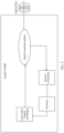
- the tunable OTDR may further locate a fault. As shown in FIG. 2 , a schematic diagram of a tunable OTDR is further provided.
- the tunable OTDR includes a laser with a tunable wavelength, an optical combiner/splitter (such as a coupler) or a circulator, a receive component, a processor, and the like.
- the laser with a tunable wavelength is configured to output test optical signals of a plurality of wavelengths.
- the optical combiner/splitter or the circulator is configured to send a test optical signal and receive a test optical signal.
- the receive component is configured to detect receive power, and the processor is configured to record a receive time, and so on.
- FIG. 2 shows only some components.
- a component such as a wavelength division multiplexer, configured to combine the service optical signal and the test optical signal may be further disposed between the tunable OTDR and an ODN.
- the component is also used when the service optical signal is sent between an OLT and the ODN.
- the fault locating method may be performed by a fault locating device, and the fault locating device may be an OLT or a tunable OTDR. Specifically, when being performed by the OLT, the fault locating method may be performed by a board in the OLT. Certainly, the fault locating device may be another device, such as a terminal or a server.
- the fault locating device includes a memory 301 and a processor 302.
- the memory 301 may be a read-only memory (Read-Only Memory, ROM), a static storage device, a dynamic storage device, or the like.
- the memory 301 may store computer instructions. When the computer instructions stored in the memory 301 are executed by the processor 302, the processor 302 is configured to perform the fault locating method.
- the memory may further store data.
- the processor 302 may be a general-purpose central processing unit (Central Processing Unit, CPU), an ASIC, a graphics processing unit (Graphics Processing Unit, GPU), or any combination thereof.
- the processor 302 may include one or more chips.
- an execution procedure of a fault locating method is provided. This procedure is described by using an example in which a fault locating apparatus is an OTDR with a tunable wavelength.
- Step 401 Obtain a first correspondence between a receive time and receive power during reverse backhaul that occurs when a test optical signal that can be reflected by a reflection component disposed at each port of at least one stage of optical splitter is in downlink transmission in an ODN, where reverse backhaul includes backscatter and reflection or includes backscatter.
- Downlink transmission refers to a transmission direction from an OLT to an ONT.
- Reverse backhaul occurs when backscatter of an optical fiber exists, or occurs when backscatter and reflection of an optical fiber exist (for example, reflection occurs when an optical fiber is broken).
- reverse backhaul may also occur when a reflection component reflects a test optical signal.
- a fault locating instruction may be sent to the OTDR (for example, the OLT sends the fault locating instruction).
- the OTDR may sequentially send test optical signals of wavelengths that can be reflected by the reflection component at each port of the at least one stage of optical splitter, and record sending times of sending the test optical signals of these wavelengths.
- a reflection component at a port that is corresponding to the wavelength and that is of the at least one stage of optical splitter in the ODN reflects (basically totally reflects) the test optical signal of the wavelength.
- test optical signal of the wavelength is completely transmitted when passing through another port in the ODN. It may be learned that the test optical signal of the wavelength is reflected and backscattered by only various optical fibers and a specific reflection component in the ODN (generally, the optical fiber only backscatters the test optical signal, and the optical fiber also reflects the test optical signal when being broken), so that a part of the test optical signal of the wavelength returns to the OTDR through reverse backhaul and is received by the OTDR.
- the OTDR may record a correspondence between a receive time and receive power.
- a first correspondence between a receive time and receive power during reverse backhaul that occurs when a test optical signal that can be reflected by a reflection component corresponding to the wavelength is in downlink transmission in the ODN is obtained. Because a test optical signal of a wavelength that can be reflected by the reflection component at each port of the at least one stage of optical splitter needs to be sent, the first correspondence between a receive time and receive power during reverse backhaul that occurs when the test optical signal that can be reflected by the reflection component disposed at each port of the at least one stage of optical splitter is in downlink transmission in the ODN may be obtained (for ease of description in the following, this description is simplified as a description that the first correspondence corresponding to each port of the at least one stage of optical splitter is obtained).
- Step 402 Determine, based on the first correspondence, a second correspondence between a transmission distance and receive power during reverse backhaul that occurs when a test optical signal is in downlink transmission in an optical fiber between each port of the at least one stage of optical splitter and a component connected to the port.
- the OTDR may determine, by using each first correspondence, the second correspondence between a transmission distance and receive power during reverse backhaul that occurs when a test optical signal is in downlink transmission in the optical fiber between each port of the at least one stage of optical splitter and the component connected to the port.
- Reverse backhaul is caused by backscatter and reflection or by backscatter.
- receive power generated by backscatter may alternatively be converted into an optical fiber loss, that is, the second correspondence may be a correspondence between the transmission distance and the optical fiber loss.
- Receive power generated after backscatter and reflection may alternatively be converted into a transmission distance and a reflection event, that is, the second correspondence may alternatively be a correspondence between the transmission distance and the reflection event.
- the at least one stage of optical splitter is an i th -stage optical splitter (i is greater than or equal to 1), and the i th -stage optical splitter is directly connected to the ONT, an optical fiber between each port of the i th -stage optical splitter and a component connected to the port may be referred to as a drop optical fiber.
- an optical fiber between each port of the i th -stage optical splitter and the (i+1) th -stage optical splitter connected to the port may be referred to as a distribution optical fiber.
- Step 403 Locate a fault in the ODN based on the second correspondence.
- the OTDR may determine, based on the second correspondence determined in step 402, whether a fault exists in the ODN, and determine a fault location point.
- the OTDR may notify operation and maintenance engineer of the fault location point in the ODN, so that the operation and maintenance engineer know fault information of the ODN in time.
- a second correspondence between a transmission distance and receive power during reverse backhaul that occurs when a test optical signal is in downlink transmission in each segment of optical fiber in the ODN may be directly obtained, so that whether a fault exists in an optical fiber (a drop optical fiber, a feeder optical fiber, and a distribution optical fiber) in the ODN can be accurately determined, and a location at which the fault occurs can be accurately determined.
- an optical fiber a drop optical fiber, a feeder optical fiber, and a distribution optical fiber
- the at least one stage of optical splitter is a first-stage optical splitter.
- the ODN includes only one stage of optical splitter, or the ODN includes a plurality of stages of optical splitters but a reflection component is disposed at each port of only the first-stage optical splitter.
- processing of determining the second correspondence may be: obtaining a third correspondence between a transmission distance in the ODN and superposed receive power of all optical fibers in the ODN; converting each first correspondence into a fourth correspondence between a transmission distance and receive power during reverse backhaul; and performing subtraction between receive power at a same transmission distance in the third correspondence and each fourth correspondence, to obtain a second correspondence between a transmission distance and receive power during reverse backhaul that occurs when a test optical signal is in downlink transmission in an optical fiber between each port of the first-stage optical splitter and a component connected to the port of the first-stage optical splitter.
- the OTDR may obtain the third correspondence.
- superposed receive power corresponding to each transmission distance is superposition of power of optical signals reflected and backscattered by all optical fibers at the transmission distance, or superposition of power of optical signals backscattered by all optical fibers at the transmission distance.
- the OTDR may determine, by using an emitting time of a test optical signal obtaining the first correspondence and the receive time in the first correspondence, a transmission time corresponding to each receive time in the first correspondence, and then determine a transmission distance by using the transmission time.
- the OTDR makes a correspondence between the transmission distance corresponding to each receive time and the receive power, to obtain a fourth correspondence between the transmission distance and the receive power.
- the OTDR may separately perform subtraction between receive power at a same transmission distance in the third correspondence and the fourth correspondence, to obtain a difference of receive power corresponding to each transmission distance in the fourth correspondence.
- the OTDR determines that a correspondence between the transmission distance and the difference of the receive power is a second correspondence between a transmission distance and receive power during reverse backhaul that occurs when a test optical signal is in downlink transmission in an optical fiber between the first port and a component connected to the first port.
- the foregoing method may be used for processing for each port of the first-stage optical splitter, to obtain the second correspondence between a transmission distance and receive power during reverse backhaul that occurs when a test optical signal is in downlink transmission in the optical fiber between each port of the first-stage optical splitter and the component connected to the port may be obtained.
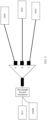
- the ODN includes a first-stage optical splitter, and the first-stage optical splitter is a 1 ⁇ 3 optical splitter, and is connected to an ONT 1, an ONT 2, and an ONT 3.
- Reflection gratings disposed at three ports (a port A, a port B, and a port C) of the first-stage optical splitter respectively reflect test optical signals of ⁇ 1, ⁇ 2 and ⁇ 3.
- the third correspondence is a correspondence between a transmission distance and superposed power for reflecting and backscattering any test optical signal by optical fibers between the ONT and the port A, the port B, and the port C, or a correspondence between a transmission distance and superposed power for backscatter.
- the reflection grating at the port A reflects most of the test optical signal of ⁇ 1, so that receive power is superposed power for reflecting and backscattering the test optical signal of ⁇ 1 by optical fibers between the ONT and the port B and the port C, or superposed power for backscatter.
- the reflection grating at the port B totally reflects the test optical signal of ⁇ 2, so that receive power is superposed power for reflecting and backscattering the test optical signal of ⁇ 2 by optical fibers between the ONT and the port A and the port C, or superposed power for backscatter.
- the reflection grating at the port C totally reflects the test optical signal of ⁇ 3, so that receive power is superposed power for reflecting and backscattering the test optical signal of ⁇ 3 by optical fibers between the ONT and the port A and the port B, or superposed power for backscatter. Therefore, the superposed power for sending the test optical signal of ⁇ 1 may be subtracted from the receive power in the third correspondence, to obtain receive power generated when an optical fiber between the port A and the ONT reflects and backscatters the test optical signal, or receive power generated during backscatter.
- the superposed power for sending the test optical signal of A 2 may be subtracted from the receive power in the third correspondence to obtain receive power generated when an optical fiber between the port B and the ONT reflects and backscatters the test optical signal, or receive power generated during backscatter.
- the superposed power for sending the test optical signal of A 3 may be subtracted from the receive power in the third correspondence, to obtain receive power generated when an optical fiber between the port C and the ONT reflects and backscatters the test optical signal, or receive power generated during backscatter. It should be noted herein that, when the superposed power is subtracted from the receive power in the third correspondence, subtraction is performed between receive power at a same transmission distance.
- the optical fiber connected to each port of the first-stage optical splitter is a drop optical fiber.
- the at least one stage of optical splitter includes a first-stage optical splitter and a second-stage optical splitter.
- the ODN includes only two stages of optical splitters, or the ODN includes a plurality of stages of optical splitters but a reflection component is disposed at each port of only the first-stage optical splitter and the second-stage optical splitter.
- processing of determining the second correspondence may be: obtaining a third correspondence between a transmission distance in the ODN and superposed receive power of all optical fibers in the ODN; determining, based on the third correspondence and a first correspondence between a receive time and receive power during reverse backhaul that occurs when a test optical signal that can be reflected by a reflection component disposed at each port of the second-stage optical splitter is in downlink transmission in the ODN, a second correspondence between a transmission distance and receive power during reverse backhaul that occurs when a test optical signal is in downlink transmission in an optical fiber between each port of the second-stage optical splitter and a component connected to the port of the second-stage optical splitter; and determining, based on each first correspondence and each second correspondence, a second correspondence between a transmission distance and receive power during reverse backhaul that occurs when a test optical signal is in downlink transmission in an optical fiber between each port of the first-stage optical splitter and a component connected to the port of the first-stage optical splitter.
- the OTDR may obtain the third correspondence.
- superposed receive power corresponding to each transmission distance is superposition of power of optical signals reflected and backscattered by all optical fibers at the transmission distance, or superposition of power of optical signals backscattered by all optical fibers at the transmission distance.
- the OTDR may determine, by using an emitting time of a test optical signal obtaining the first correspondence and the receive time in the first correspondence, a transmission distance corresponding to each receive time in the first correspondence. Then, the OTDR makes a correspondence between the transmission distance corresponding to each receive time and the receive power, to obtain a fourth correspondence between the transmission distance and the receive power. The OTDR may separately perform subtraction between receive power at a same transmission distance in the third correspondence and the fourth correspondence, to obtain a difference of receive power corresponding to each transmission distance in the fourth correspondence.
- the OTDR determines that a correspondence between the transmission distance and the difference of the receive power is a second correspondence between a transmission distance and receive power during reverse backhaul that occurs when a test optical signal is in downlink transmission in an optical fiber between the second port and a component connected to the second port.
- the OTDR may obtain a first correspondence corresponding to each port of the first-stage optical splitter, and then convert, into a transmission distance, a receive time in the first correspondence corresponding to each port, that is, convert the first correspondence into a correspondence between the transmission distance and the receive power.
- the OTDR may obtain second correspondences separately corresponding to optical fibers connected to all ports of the second-stage optical splitter connected to the first port.
- P11 is the sum of receive power at the first transmission distance in the first correspondence corresponding to ports other than the first port in the first-stage optical splitter;
- P0 is receive power at the first transmission distance in the first correspondence corresponding to the first port in the first-stage optical splitter;
- P21 is the sum of receive power at the first transmission distance in second correspondences corresponding to optical fibers separately connected to all the ports in the second-stage optical splitter connected to the first port; and
- n is a quantity of ports other than the first port in the first-stage optical splitter.
- the second correspondence corresponding to the optical fiber connected to the first port may be determined. This manner may be used for each port of the first-stage optical splitter, to obtain second correspondences corresponding to optical fibers connected to all the ports.
- the ODN includes a first-stage optical splitter and a second-stage optical splitter.
- the second-stage optical splitter is connected to an ONT.
- the first-stage optical splitter is a 1 *2 optical splitter.
- the second-stage optical splitter includes two 1 *2 optical splitters. Reflection gratings at two ports of the first-stage optical splitter respectively reflect test optical signals of A 1 and A 2.
- Optical fibers connected to the two ports are respectively A and B.
- Reflection gratings at ports of the two 1 *2 optical splitters of the second-stage optical splitter respectively reflect test optical signals of A 3, A 4, A 5, and A 6.
- Optical fibers connected to the ports are respectively C, D, E and F.
- the OTDR may sequentially send the test optical signals of ⁇ 1, ⁇ 2, ⁇ 3, ⁇ 4, ⁇ 5, and A 6, to obtain a first correspondence corresponding to each port.
- Receive power in a first correspondence corresponding to a port at which a reflection component of A 1 is located is superposition of B, E, and F (that is, B+E+F).
- receive power in a first correspondence corresponding to a port at which a reflection component of A 2 is located is superposition of A, C, and D (that is, A+C+D).
- Receive power in a first correspondence corresponding to a port at which a reflection component of A 3 is located is superposition of A, B, D, E, and F (that is, A+B+D+E+F).
- Receive power in a first correspondence corresponding to a port at which a reflection component of A 4 is located is superposition of A, B, C, E, and F (that is, A+B+C+E+F).
- Receive power in a first correspondence corresponding to a port at which a reflection component of A 5 is located is superposition of A, B, C, D, and F (that is, A+B+C+D+F).
- Receive power in a first correspondence corresponding to a port at which a reflection component of A 6 is located is superposition of A, B, C, D, and E (that is, A+B+C+D+E). Therefore, when a second correspondence corresponding to A is determined, C and D may be subtracted from A+C+D.
- E and F may be subtracted from B+E+F.
- A+B+D+E+F may be subtracted from A+B+C+D+E+F.
- A+B+C+E+F may be subtracted from A+B+C+D+E+F.
- A+B+C+D+E may be subtracted from A+B+C+D+E+F.
- A+B+C+D+E may be subtracted from A+B+C+D+E+F.
- the second correspondence corresponding to the optical fiber connected to each port in the ODN may be obtained in this manner. It should be noted herein that, the subtracting C and D from A+C+D is subtraction between receive power at a same transmission distance. Other cases are similar to this case, and details are not described herein again.
- Superposition of B, E, and F is power of a test optical signal that is received by the OTDR after the three segments of optical fibers B, E, and F separately backscatter or backscatter and reflect the test optical signal.
- third correspondences that are between a transmission distance and receive power and that are corresponding to all optical fibers in the ODN may be determined in the following two manners.
- Manner 1 A correspondence between a transmission distance and receive power during reverse backhaul that occurs when a test optical signal of a first wavelength is in downlink transmission in the ODN is obtained, and the correspondence is determined as a third correspondence between a transmission distance in the ODN and superposed receive power of all optical fibers in the ODN, where the first wavelength is different from a wavelength of a test optical signal that can be reflected by the reflection component at each port of the at least one stage of optical splitter.
- the first wavelength is different from a wavelength of a test optical signal that can be reflected by each port of the at least one stage of optical splitter.
- a fault locating instruction may be sent to the OTDR.
- the OTDR may send the test optical signal of the first wavelength, and record a sending time of sending the test optical signal of the first wavelength.
- test optical signal of the first wavelength passes through the ODN, all the reflection components disposed at the ports of the at least one stage of optical splitter in the ODN transmit the test optical signal of the first wavelength, and only various optical fibers and optical splitters in the ODN reflect and backscatter or backscatter the test optical signal of the first wavelength (reflection occurs at a location of a broken optical fiber or a reflection component), so that a part of the test optical signal of the first wavelength returns to the OTDR and is received by the OTDR.
- the OTDR may record a correspondence between a receive time and receive power, and then determine a transmission distance by using a difference between the receive time and a sending time (the transmission distance can be directly determined by using the foregoing formula, and details are not described herein), to obtain a correspondence between a transmission distance and receive power, that is, obtain the third correspondence. Because none of the reflection components in the ODN reflects the test optical signal of the first wavelength, the test optical signal of the first wavelength can pass through all the optical fibers in the ODN. Therefore, detected receive power is superposed power obtained after all the optical fibers backscatter the test optical signal of the first wavelength, or superposed power obtained after backscatter and reflection. It should be noted herein that the third correspondence may be obtained first, and then the first correspondence is determined, or the first correspondence may be determined first, and then the third correspondence is determined. This is not limited in this embodiment of this application.
- a third correspondence between a transmission distance in the ODN and superposed receive power of all optical fibers in the ODN is determined based on a first correspondence between a receive time and receive power during reverse backhaul that occurs when a test optical signal that can be reflected by a reflection component disposed at each port of the first-stage optical splitter is in downlink transmission in the ODN.
- the OTDR may convert the first correspondence corresponding to each port of the first-stage optical splitter into a correspondence between a transmission distance and receive power. Afterwards, the OTDR adds up receive power at a same transmission distance in these correspondences to obtain a value, and then divides (m-1) by the value to obtain receive power at the same transmission distance. In this manner, receive power at each transmission distance is determined, and a correspondence may be made between the transmission distance and the receive power to obtain the third correspondences that are between the transmission distance and the receive power and that are corresponding to all the optical fibers in the ODN. In this way, a wavelength adjustment range of the OTDR can be reduced.
- m is a quantity of ports of the first-stage optical splitter.
- a fault may be located in the ODN in the following manner.
- the abnormal location point is determined as a fault location point of the optical fiber between the first port and the component connected to the first port.
- the OTDR may view, in the second correspondence corresponding to the optical fiber connected to each port of the at least one stage of optical splitter, whether an abnormal location point at which receive power suddenly changes exists. If an abnormal location point exists in a second correspondence corresponding to an optical fiber connected to a target port, it is determined that the optical fiber connected to the target port is a faulty optical fiber in the ODN, the abnormal location point may be determined as a fault location point of the optical fiber connected to the target port. In this way, not only a faulty optical fiber in the ODN is provided, but also a location point at which the optical fiber is faulty is provided.
- an abnormal location point at which receive power suddenly changes can be determined based on the second correspondence due to the following reason: Normally, when a test optical signal is transmitted in an optical fiber, receive power becomes smaller as a transmission distance becomes longer (this is described for only transmission in the optical fiber, and the receive power also becomes larger, because the test optical signal is transmitted to the ONT). However, when the optical fiber is split or broken, there is a relatively large reflectivity on the test optical signal, which causes relatively large receive power. Therefore, a fault location may be determined based on a location point at which receive power suddenly changes.
- the OLT may establish a communication connection to the OTDR, and obtain the first correspondence from the OTDR and a sending time corresponding to each receive time in the first correspondence. Then, the OLT performs subsequent processing based on the first correspondence, and the subsequent processing is the same as that performed by the OTDR. Details are not described herein again.
- the receive power may alternatively be converted into an optical fiber loss to locate a fault in the ODN.
- a correspondence between a transmission distance and receive power during reverse backhaul that occurs when a test optical signal is in downlink transmission in each optical fiber in the ODN is obtained to accurately determine whether the optical fiber is faulty. Therefore, a fault can be more accurately located in the ODN.
- FIG. 7 is a diagram of a structure of a fault locating apparatus according to an embodiment of this application.
- the apparatus may be completely or partially implemented by using software, hardware, or a combination thereof.
- the apparatus is applied to a passive optical network.
- the passive optical network includes an ODN, and a reflection component reflecting test optical signals of different wavelengths is disposed at each port of at least one stage of optical splitter in the ODN.
- the apparatus provided in this embodiment of this application may implement the procedure in FIG. 4 in the embodiments of this application.
- the apparatus includes an obtaining module 710 and a determining module 720.
- the obtaining module 710 is configured to obtain a first correspondence between a receive time and receive power during reverse backhaul that occurs when a test optical signal that can be reflected by the reflection component disposed at each port of the at least one stage of optical splitter is in downlink transmission in the ODN, where reverse backhaul includes backscatter and reflection or includes backscatter.
- the obtaining module 710 may be specifically configured to implement an obtaining function in step 401 and a hidden step included in step 401.
- the determining module 720 is configured to: determine, based on the first correspondence, a second correspondence between a transmission distance and receive power during reverse backhaul that occurs when a test optical signal is in downlink transmission in an optical fiber between each port of the at least one stage of optical splitter and a component connected to the port; and locate a fault in the ODN based on the second correspondence.
- the determining module 720 may be specifically configured to implement determining functions in step 402 and step 403, and hidden steps included in step 402 and step 403.
- the at least one stage of optical splitter is a first-stage optical splitter.
- the determining module 720 is configured to:
- the at least one stage of optical splitter includes a first-stage optical splitter and a second-stage optical splitter.
- the determining module 720 is configured to:
- the determining module 720 is configured to:
- the determining module 720 is configured to: if it is determined, based on a second correspondence between a transmission distance and receive power during reverse backhaul that occurs when a test optical signal is in downlink transmission in an optical fiber between a target port of the at least one stage of optical splitter and a component connected to the target port, that an abnormal location point at which receive power suddenly changes exists, determine the abnormal location point as a fault location point of the optical fiber between the target port and the component connected to the target port.
- Division into the modules in embodiments of this application is an example, is merely division into logical functions, and may be other division during actual implementation.
- functional modules in embodiments of this application may be integrated into one processor, or each of the modules may exist alone physically, or two or more modules may be integrated into one module.
- the integrated module may be implemented in a form of hardware, or may be implemented in a form of a software functional module.
- the foregoing embodiments may be completely or partially implemented by using software, hardware, firmware, or any combination thereof.
- the foregoing embodiments may be completely or partially implemented in a form of a computer program product.
- the computer program product includes one or more computer instructions.
- the computer instructions may be stored in a computer-readable storage medium or transmitted from one computer-readable storage medium to another computer-readable storage medium.
- the computer-readable storage medium may be any usable medium accessible by the OLT, or a data storage device, such as a server or a data center, integrating one or more usable media.
- the usable medium may be a magnetic medium (such as a floppy disk, a hard disk, or a magnetic tape), or may be an optical medium (such as a digital video disk (Digital Video Disk, DVD)) or a semiconductor medium (such as a solid-state disk).
- a magnetic medium such as a floppy disk, a hard disk, or a magnetic tape
- an optical medium such as a digital video disk (Digital Video Disk, DVD)
- a semiconductor medium such as a solid-state disk.
Landscapes
- Engineering & Computer Science (AREA)
- Computer Networks & Wireless Communication (AREA)
- Physics & Mathematics (AREA)
- Electromagnetism (AREA)
- Signal Processing (AREA)
- Computing Systems (AREA)
- Optical Communication System (AREA)
- Testing Of Optical Devices Or Fibers (AREA)
Applications Claiming Priority (2)
| Application Number | Priority Date | Filing Date | Title |
|---|---|---|---|
| CN202010357617.4A CN111669221B (zh) | 2020-04-29 | 2020-04-29 | 故障定位的方法、装置和系统 |
| PCT/CN2020/132534 WO2021218145A1 (fr) | 2020-04-29 | 2020-11-28 | Procédé, appareil et système de localisation de défaillance |
Publications (3)
| Publication Number | Publication Date |
|---|---|
| EP4135219A1 true EP4135219A1 (fr) | 2023-02-15 |
| EP4135219A4 EP4135219A4 (fr) | 2023-09-13 |
| EP4135219B1 EP4135219B1 (fr) | 2026-03-04 |
Family
ID=72382923
Family Applications (1)
| Application Number | Title | Priority Date | Filing Date |
|---|---|---|---|
| EP20933243.6A Active EP4135219B1 (fr) | 2020-04-29 | 2020-11-28 | Procédé, appareil et système de localisation de défaillance |
Country Status (8)
| Country | Link |
|---|---|
| US (1) | US12231162B2 (fr) |
| EP (1) | EP4135219B1 (fr) |
| JP (1) | JP7522227B2 (fr) |
| KR (1) | KR102693346B1 (fr) |
| CN (1) | CN111669221B (fr) |
| BR (1) | BR112022021661A2 (fr) |
| MX (1) | MX2022013688A (fr) |
| WO (1) | WO2021218145A1 (fr) |
Families Citing this family (9)
| Publication number | Priority date | Publication date | Assignee | Title |
|---|---|---|---|---|
| CN111669221B (zh) * | 2020-04-29 | 2021-09-21 | 华为技术有限公司 | 故障定位的方法、装置和系统 |
| CN114679640B (zh) * | 2020-12-24 | 2024-12-24 | 中国电信股份有限公司 | 光网络的资源管理系统中异常端口用户的检测方法及装置 |
| CN116865848A (zh) * | 2022-03-28 | 2023-10-10 | 华为技术有限公司 | 光链路检测方法及装置 |
| CN115021807B (zh) * | 2022-05-27 | 2024-07-23 | 中国电信股份有限公司 | 分光器的监测方法及分光监测系统 |
| CN115396017B (zh) * | 2022-08-22 | 2025-08-29 | 国网青海省电力公司信息通信公司 | 光纤线路的故障识别方法及装置 |
| CN119729559B (zh) * | 2023-09-27 | 2025-10-10 | 大唐移动通信设备有限公司 | 下行链路的故障检测方法、装置、接入网设备及介质 |
| CN118199719A (zh) * | 2024-04-25 | 2024-06-14 | 深圳市光网世纪科技有限公司 | 针对光纤链路的故障定位方法、设备及介质 |
| CN120979546A (zh) * | 2024-05-15 | 2025-11-18 | 华为技术有限公司 | 信号处理的方法、装置及系统 |
| CN118464377B (zh) * | 2024-07-10 | 2024-09-06 | 国网浙江省电力有限公司宁波市鄞州区供电公司 | 一种光纤故障定位方法、装置、电子设备及存储介质 |
Family Cites Families (35)
| Publication number | Priority date | Publication date | Assignee | Title |
|---|---|---|---|---|
| JP4932197B2 (ja) * | 2005-09-02 | 2012-05-16 | 株式会社フジクラ | 光線路障害監視装置及び方法 |
| KR100663462B1 (ko) * | 2005-11-23 | 2007-01-02 | 삼성전자주식회사 | 수동형 광 가입자 망 |
| JP4902213B2 (ja) * | 2006-02-03 | 2012-03-21 | 株式会社フジクラ | 光線路監視装置及び方法 |
| WO2007088976A1 (fr) * | 2006-02-03 | 2007-08-09 | Fujikura Ltd. | Dispositif et procede de surveillance du trajet d'un faisceau lumineux |
| CN101688819B (zh) * | 2007-03-28 | 2014-01-29 | 爱斯福公司 | 用于确定差分群时延和偏振模色散的方法和设施 |
| EP2425556B1 (fr) * | 2009-04-30 | 2019-10-30 | Telefonaktiebolaget LM Ericsson (publ) | Procédé et appareil pour découverte de défaut dans un réseau optique passif (pon) |
| TWI406526B (zh) * | 2009-06-12 | 2013-08-21 | Univ Nat Taiwan Science Tech | 用於光網路監控及錯誤檢測之光信號切換模組 |
| JP5652889B2 (ja) * | 2009-07-15 | 2015-01-14 | ピーエムシー−シエラ イスラエル,エルティディ. | 受動的光ネットワーク(pon)インバンド光学的時間範囲反射率測定器(otdr) |
| CN102082605B (zh) * | 2009-12-01 | 2014-03-12 | 华为技术有限公司 | 光网络测试方法、装置及系统 |
| CN102244538B (zh) * | 2010-05-10 | 2015-06-17 | 华为技术有限公司 | 分支光纤检测系统及方法、光分配网络和分光器 |
| CN102244539B (zh) * | 2010-05-11 | 2014-09-17 | 华为技术有限公司 | 分支光纤检测方法及系统、无源光网络和分光器 |
| EP2656515B1 (fr) * | 2010-12-22 | 2015-02-18 | Telefonaktiebolaget L M Ericsson (PUBL) | Analyse de trace otdr dans des systèmes pon |
| JP2012173184A (ja) * | 2011-02-23 | 2012-09-10 | Kddi Corp | 光多重反射点特定装置及び方法 |
| EP2726836B1 (fr) * | 2011-06-30 | 2020-06-24 | Telefonaktiebolaget LM Ericsson (publ) | Analyse de trace rdto dans des systèmes rop |
| WO2013006100A1 (fr) * | 2011-07-01 | 2013-01-10 | Telefonaktiebolaget L M Ericsson (Publ) | Dispositif, nœud à distance et procédés pour supervision de pon |
| CN202206397U (zh) * | 2011-08-30 | 2012-04-25 | 上海波汇通信科技有限公司 | 无源光网络故障监测装置 |
| CN102571199B (zh) * | 2011-12-31 | 2016-01-20 | 中兴通讯股份有限公司 | 一种光纤故障检测方法及装置 |
| WO2012095044A2 (fr) * | 2012-02-21 | 2012-07-19 | 华为技术有限公司 | Module d'émission-réception optique, système de réseau optique passif, procédé et système de détection à fibre optique |
| CN102594452A (zh) * | 2012-03-15 | 2012-07-18 | 武汉光迅科技股份有限公司 | 一种自诊断无源光网络系统 |
| CN103107842B (zh) * | 2012-09-05 | 2015-11-25 | 华为技术有限公司 | 分光器端口识别系统 |
| CN103229433B (zh) * | 2012-11-29 | 2016-08-03 | 华为技术有限公司 | 一种光线路终端、光时域反射计及光信号收发方法和系统 |
| CN103036615B (zh) * | 2012-12-19 | 2015-10-28 | 青岛海信宽带多媒体技术有限公司 | 光时域检测仪光模块及吉比特无源光网络断点检测系统 |
| CN103281609A (zh) * | 2013-06-19 | 2013-09-04 | 苏州彩云飞电子有限公司 | 多波长无源光网络系统 |
| CN104426603A (zh) * | 2013-08-30 | 2015-03-18 | 华为技术有限公司 | 光网络检测方法、装置、设备、系统及分光器 |
| CN104579459B (zh) * | 2013-10-25 | 2018-03-16 | 华为技术有限公司 | 一种光纤链路识别的方法、设备和系统 |
| CN103957052A (zh) * | 2014-05-12 | 2014-07-30 | 华为技术有限公司 | 光纤故障定位方法、光模块及光纤网络单元 |
| US9752955B2 (en) * | 2014-07-31 | 2017-09-05 | Ii-Vi Incorporated | Edge propagating optical time domain reflectometer and method of using the same |
| CN105530046B (zh) * | 2014-09-30 | 2018-06-12 | 中国电信股份有限公司 | 实现光功率和分支衰减故障自动测试的方法和系统 |
| CN104935378B (zh) * | 2015-06-05 | 2017-12-19 | 烽火通信科技股份有限公司 | 一种用于无源光网络的光纤链路检测系统及方法 |
| CN106911378A (zh) * | 2015-12-23 | 2017-06-30 | 中国电信股份有限公司 | 实现光路检测的方法、管理系统及光时域反射仪设备 |
| CN110474678B (zh) * | 2019-08-22 | 2021-06-01 | 华为技术有限公司 | 一种光纤编码的获取方法、系统以及相关设备 |
| CN110996193B (zh) * | 2019-11-19 | 2021-10-26 | 华为技术有限公司 | 识别光网络单元连接端口的方法、相关装置及系统 |
| CN111010228B (zh) * | 2019-11-19 | 2023-01-13 | 华为技术有限公司 | 一种端口识别的方法、装置、系统和分光器 |
| CN111669221B (zh) * | 2020-04-29 | 2021-09-21 | 华为技术有限公司 | 故障定位的方法、装置和系统 |
| CN115579725A (zh) * | 2022-12-02 | 2023-01-06 | 武汉灵途传感科技有限公司 | 一种mopa激光器系统 |
-
2020
- 2020-04-29 CN CN202010357617.4A patent/CN111669221B/zh active Active
- 2020-11-28 WO PCT/CN2020/132534 patent/WO2021218145A1/fr not_active Ceased
- 2020-11-28 EP EP20933243.6A patent/EP4135219B1/fr active Active
- 2020-11-28 BR BR112022021661A patent/BR112022021661A2/pt unknown
- 2020-11-28 MX MX2022013688A patent/MX2022013688A/es unknown
- 2020-11-28 KR KR1020227040077A patent/KR102693346B1/ko active Active
- 2020-11-28 JP JP2022565953A patent/JP7522227B2/ja active Active
-
2022
- 2022-10-28 US US17/976,558 patent/US12231162B2/en active Active
Also Published As
| Publication number | Publication date |
|---|---|
| MX2022013688A (es) | 2022-11-30 |
| CN111669221B (zh) | 2021-09-21 |
| EP4135219A4 (fr) | 2023-09-13 |
| KR102693346B1 (ko) | 2024-08-09 |
| US12231162B2 (en) | 2025-02-18 |
| JP7522227B2 (ja) | 2024-07-24 |
| WO2021218145A1 (fr) | 2021-11-04 |
| BR112022021661A2 (pt) | 2022-12-20 |
| EP4135219B1 (fr) | 2026-03-04 |
| KR20230002795A (ko) | 2023-01-05 |
| US20230052962A1 (en) | 2023-02-16 |
| CN111669221A (zh) | 2020-09-15 |
| JP2023523080A (ja) | 2023-06-01 |
Similar Documents
| Publication | Publication Date | Title |
|---|---|---|
| EP4135219B1 (fr) | Procédé, appareil et système de localisation de défaillance | |
| KR101751158B1 (ko) | 광 네트워크 검출 방법, 장치 및 시스템 | |
| US12101117B2 (en) | Port identification method, apparatus, and system | |
| US11050485B2 (en) | High-precision and large-dynamic-range fault monitoring device and method for WDM-PON | |
| CN110945800A (zh) | 一种光性能监测装置及方法 | |
| US20230261757A1 (en) | Port Identification Method and Apparatus | |
| EP3869709B1 (fr) | Système de réflectométrie de domaine temporel optique (otdr) pour le diagnostic d'un réseau optique passif (pon) | |
| JP4932197B2 (ja) | 光線路障害監視装置及び方法 | |
| US12088337B2 (en) | Systems and methods for detecting a location of the optical elements causing multipath interference in an optical link | |
| CN121126149A (zh) | 光通信系统、端口连接关系的确定方法、装置、设备及存储介质 | |
| CN117956326A (zh) | 光链路信息构建方法、系统、设备及计算机可读存储介质 | |
| CN120880549A (zh) | 一种测试方法、测试装置、测试系统及存储介质 | |
| Araki et al. | A new optical fiber line testing function for service construction work that checks for optical filters below an optical splitter in a PON |
Legal Events
| Date | Code | Title | Description |
|---|---|---|---|
| STAA | Information on the status of an ep patent application or granted ep patent |
Free format text: STATUS: THE INTERNATIONAL PUBLICATION HAS BEEN MADE |
|
| PUAI | Public reference made under article 153(3) epc to a published international application that has entered the european phase |
Free format text: ORIGINAL CODE: 0009012 |
|
| STAA | Information on the status of an ep patent application or granted ep patent |
Free format text: STATUS: REQUEST FOR EXAMINATION WAS MADE |
|
| 17P | Request for examination filed |
Effective date: 20221107 |
|
| AK | Designated contracting states |
Kind code of ref document: A1 Designated state(s): AL AT BE BG CH CY CZ DE DK EE ES FI FR GB GR HR HU IE IS IT LI LT LU LV MC MK MT NL NO PL PT RO RS SE SI SK SM TR |
|
| DAV | Request for validation of the european patent (deleted) | ||
| DAX | Request for extension of the european patent (deleted) | ||
| A4 | Supplementary search report drawn up and despatched |
Effective date: 20230810 |
|
| RIC1 | Information provided on ipc code assigned before grant |
Ipc: H04B 10/077 20130101ALI20230804BHEP Ipc: H04B 10/272 20130101ALI20230804BHEP Ipc: H04Q 11/00 20060101ALI20230804BHEP Ipc: H04B 10/071 20130101AFI20230804BHEP |
|
| GRAP | Despatch of communication of intention to grant a patent |
Free format text: ORIGINAL CODE: EPIDOSNIGR1 |
|
| STAA | Information on the status of an ep patent application or granted ep patent |
Free format text: STATUS: GRANT OF PATENT IS INTENDED |
|
| INTG | Intention to grant announced |
Effective date: 20250624 |
|
| GRAJ | Information related to disapproval of communication of intention to grant by the applicant or resumption of examination proceedings by the epo deleted |
Free format text: ORIGINAL CODE: EPIDOSDIGR1 |
|
| STAA | Information on the status of an ep patent application or granted ep patent |
Free format text: STATUS: REQUEST FOR EXAMINATION WAS MADE |
|
| GRAP | Despatch of communication of intention to grant a patent |
Free format text: ORIGINAL CODE: EPIDOSNIGR1 |
|
| STAA | Information on the status of an ep patent application or granted ep patent |
Free format text: STATUS: GRANT OF PATENT IS INTENDED |
|
| INTC | Intention to grant announced (deleted) | ||
| INTG | Intention to grant announced |
Effective date: 20251014 |
|
| GRAS | Grant fee paid |
Free format text: ORIGINAL CODE: EPIDOSNIGR3 |
|
| GRAA | (expected) grant |
Free format text: ORIGINAL CODE: 0009210 |
|
| STAA | Information on the status of an ep patent application or granted ep patent |
Free format text: STATUS: THE PATENT HAS BEEN GRANTED |
|
| AK | Designated contracting states |
Kind code of ref document: B1 Designated state(s): AL AT BE BG CH CY CZ DE DK EE ES FI FR GB GR HR HU IE IS IT LI LT LU LV MC MK MT NL NO PL PT RO RS SE SI SK SM TR |
|
| REG | Reference to a national code |
Ref country code: CH Ref legal event code: F10 Free format text: ST27 STATUS EVENT CODE: U-0-0-F10-F00 (AS PROVIDED BY THE NATIONAL OFFICE) Effective date: 20260304 Ref country code: GB Ref legal event code: FG4D |
|
| REG | Reference to a national code |
Ref country code: IE Ref legal event code: FG4D |
|
| REG | Reference to a national code |
Ref country code: DE Ref legal event code: R096 Ref document number: 602020068236 Country of ref document: DE |