EP4135548B1 - Vorrichtung zum verbinden des unterschenkels eines skifahrers mit einer skibindung und schuhaufbau mit einer solchen vorrichtung - Google Patents
Vorrichtung zum verbinden des unterschenkels eines skifahrers mit einer skibindung und schuhaufbau mit einer solchen vorrichtung Download PDFInfo
- Publication number
- EP4135548B1 EP4135548B1 EP21722107.6A EP21722107A EP4135548B1 EP 4135548 B1 EP4135548 B1 EP 4135548B1 EP 21722107 A EP21722107 A EP 21722107A EP 4135548 B1 EP4135548 B1 EP 4135548B1
- Authority
- EP
- European Patent Office
- Prior art keywords
- skier
- axis
- lower leg
- footwear assembly
- ski
- Prior art date
- Legal status (The legal status is an assumption and is not a legal conclusion. Google has not performed a legal analysis and makes no representation as to the accuracy of the status listed.)
- Active
Links
Images


Classifications
-
- A—HUMAN NECESSITIES
- A43—FOOTWEAR
- A43B—CHARACTERISTIC FEATURES OF FOOTWEAR; PARTS OF FOOTWEAR
- A43B5/00—Footwear for sporting purposes
- A43B5/04—Ski or like boots
-
- A—HUMAN NECESSITIES
- A43—FOOTWEAR
- A43B—CHARACTERISTIC FEATURES OF FOOTWEAR; PARTS OF FOOTWEAR
- A43B5/00—Footwear for sporting purposes
- A43B5/04—Ski or like boots
- A43B5/0427—Ski or like boots characterised by type or construction details
- A43B5/0468—Adjustment of the angle of the boot to the ski
-
- A—HUMAN NECESSITIES
- A43—FOOTWEAR
- A43B—CHARACTERISTIC FEATURES OF FOOTWEAR; PARTS OF FOOTWEAR
- A43B5/00—Footwear for sporting purposes
- A43B5/04—Ski or like boots
- A43B5/0415—Accessories
- A43B5/0417—Accessories for soles or associated with soles of ski boots; for ski bindings
- A43B5/0423—Accessories for soles or associated with soles of ski boots; for ski bindings located on the sides of the sole
-
- A—HUMAN NECESSITIES
- A43—FOOTWEAR
- A43B—CHARACTERISTIC FEATURES OF FOOTWEAR; PARTS OF FOOTWEAR
- A43B5/00—Footwear for sporting purposes
- A43B5/04—Ski or like boots
- A43B5/0427—Ski or like boots characterised by type or construction details
- A43B5/0429—Adjustment of the boot to calf or shin, i.e. fibula, tibia
- A43B5/0431—Adjustment of the boot to calf or shin, i.e. fibula, tibia to the length of calf or shin, i.e. fibula, tibia
-
- A—HUMAN NECESSITIES
- A63—SPORTS; GAMES; AMUSEMENTS
- A63C—SKATES; SKIS; ROLLER SKATES; DESIGN OR LAYOUT OF COURTS, RINKS OR THE LIKE
- A63C10/00—Snowboard bindings
- A63C10/24—Calf or heel supports, e.g. adjustable high back or heel loops
-
- A—HUMAN NECESSITIES
- A43—FOOTWEAR
- A43B—CHARACTERISTIC FEATURES OF FOOTWEAR; PARTS OF FOOTWEAR
- A43B5/00—Footwear for sporting purposes
- A43B5/04—Ski or like boots
- A43B5/0427—Ski or like boots characterised by type or construction details
- A43B5/0452—Adjustment of the forward inclination of the boot leg
- A43B5/0454—Adjustment of the forward inclination of the boot leg including flex control; Dampening means
- A43B5/0456—Adjustment of the forward inclination of the boot leg including flex control; Dampening means with the actuator being disposed at the rear side of the boot
Definitions
- the invention relates to a device for connecting the lower leg of a skier to a ski binding.
- the invention also covers the footwear assembly incorporating said device.
- ski boot technology has changed little over time and only offers approximate foot comfort, while the practice requires increased comfort for the practitioners.
- ski boots are made of relatively rigid plastic and have two rigid articulated parts. The vertical part of the ski boot receives part of the tibia and the calf and the horizontal part receives the foot itself. The amplitude of the ankle flexion in such boots is very limited, only a few degrees. Adjustment means have been provided to adjust this amplitude but over extremely limited ranges. During practice, there are movements of the foot and movements of the boot that are different.
- One area of the foot is particularly stressed mechanically, at the level of the talus which is compressed during flexion movements.
- the upper part of the shell comes to bear on the upper of the shell and exerts significant pressure.
- This is a real source of discomfort and trauma.
- pressure on the malleoli can chew the flesh and cause localized heating.
- the pressure, during flexion the pressure can also be concentrated at the top of the part located around the lower leg and cause certain discomfort due to a concentration of efforts.
- Another solution is to have a shell shoe for the foot only and a lever with a headband is connected in an articulated manner to said shell and by its other end to the calf or at least to the lower leg by a headband with tightening means.
- Mechanical stops limit the amplitudes of flexion.
- the result can only be based on the average of the results acquired.
- the present invention proposes a device for connecting the lower leg of a skier with a ski binding aimed at replacing the part capable of receiving the tibia with a lighter and more comfortable tibia support system, eliminating the effects of misalignment at the ankle and the lack of parallelism between the tibia and the upper part while meeting the different functions of connecting the skier's body with the ski for better control during practice, for adjustable thermal insulation and improved sealing, without intermediate elements likely to interfere while ensuring excellent ventilation of the foot with evacuation of the humidity produced.
- the invention covers the footwear assembly equipped with the connecting device according to the present invention.
- the present invention also proposes a footwear assembly that allows the skier to wear only one pair of boots, that avoids any constraints on the foot related to wearing a shell, in particular eliminating pressure on the talus and/or on the malleoli, that includes a high tibial connection to allow better control of the practice, that allows modifications of the insulation according to the season of practice, that ensures better comfort by ventilation if necessary, that can be equipped with a device for connecting the lower leg of a skier with a lighter and more comfortable ski binding, eliminating the effects of misalignment at the ankle and the lack of parallelism between the tibia and the upper part while meeting the different functions of connecting the skier's body with the ski for better control during practice.
- the present invention thus makes it possible to solve numerous technical problems by improving the comfort of the practitioner, by proposing a much lighter device and adaptability according to the season, ski conditions, type or discipline of skiing practiced.
- the present invention allows for quick repairs without special tools, a reduced manufacturing cost and a limited quantity of material.
- the invention relates to a connecting device according to claim 1.
- the securing means may comprise a collar comprising at least one strip whose ends are provided with self-gripping means.
- the tibial connection may comprise two rigid rods, left and right.
- the two rigid rods, right and left may be attached, by their upper ends, to the same fixing means and each of the rigid rods may be articulated at the bottom around its own pivoting connection, right and left.
- the tibial connection may comprise a rod of semi-enveloping shape.
- the tibial connection may comprise a rigid semi-enveloping part provided, in the upper part, with two lateral rods and in the lower part, with two lateral straps.
- the straps may extend obliquely with respect to the lateral rods, and may in particular be connected by a transverse connecting part.
- the articulation means may comprise a degree of freedom in translation and a degree of freedom in rotation.
- the articulation means comprise a mushroom-shaped pin with a body and a head, integral with the means of securing to the lower leg and comprise a longitudinal slot provided at the upper end of the rigid rod, through which the body of said pin passes, this slot having a width less than the diameter of the head, so that the body of said pin slides in this longitudinal slot while the head of said pin retains said upper end of the rigid rod of said tibial connection.
- the articulation means may comprise a flange in which the upper end of the rigid rod slides.
- the flange may be of rectangular section and the end of the rigid rod may be rectangular and of width and length less than those of the flange.
- the invention also relates to a footwear assembly equipped with the connecting device according to the invention.
- the footwear assembly is characterized in that it comprises a base sole intended to receive a shoe, said base sole comprising at least one lateral lug, substantially vertical, the end of each lateral lug being intended to receive the pivot connection of each rigid upper.
- the base sole comprises two lateral ears, right and left.
- the end of each lateral ear being intended to receive the pivot connection of each corresponding rigid rod, right or left.
- the end of each lateral ear being intended to receive one of the pivot connections of the rigid rod of semi-enveloping shape.
- one or more angular stops, front and/or rear can be positioned on the or each lateral ear.
- each lateral ear rises substantially in line with the axis of the skier's ankle, such that the axis of the pivot connection is at least close to the axis of rotation of the ankle.
- each lateral ear may extend such that the axis of the pivot connection is substantially offset from the axis of the ankle, for example by being positioned above the talus of the foot.
- each lateral ear may extend obliquely, and in particular towards the front of the base sole.
- the end of each lateral ear rises vertically while being offset from the axis of the ankle.
- the connecting device comprises a hinge fixedly connected to the straps of the tibial connection, for example by being mounted on the transverse connecting piece.
- each lateral lug is connected to said hinge to form a pivot connection.
- the base sole comprises at the front and at the rear ends and respectively, having a profile conjugate to that of the ski binding.
- the lightweight shoe comprises a rigid sole provided with a first part of removable fastening means, the second part of these removable fastening means being carried by the base sole.
- the removable fastening means may comprise screws, snap-on or slide fastenings.
- the footwear assembly comprises at least one waterproof envelope, of tubular shape with a barrel, a lower opening, an upper opening and an opening for putting on.
- the waterproof envelope is in particular made of waterproof fabric.
- the lower opening can have a profile adapted to the peripheral shape of the base sole and the upper opening can be linked to the fastening means.
- a front or rear opening, for example of the zipper type, can be provided in the waterproof envelope, in particular along a vertical longitudinal line.
- the footwear assembly comprises an insulating layer, in a fixed lining by gluing or in a removable lining of the waterproof envelope so as to ensure thermal insulation.
- the footwear assembly comprises a mechanical pump for ventilation of the interior of the envelope.
- perforations may be provided in the shoe.
- the footwear assembly comprises shock-absorbing means, interposed between the base sole and at least one of the rigid rods of the connecting means.
- the shock-absorbing means may comprise a mechanical spring cylinder housed in two cylindrical half-bodies capable of sliding coaxially.
- the shock-absorbing means may comprise a gas cylinder, an oil cylinder, a mixed cylinder or a coupling of two cylinders.
- the footwear assembly comprises means for adjusting the coincidence of the axis of the pivot connection with the axis of rotation of the ankle.
- the adjustment means may be of the single or double eccentric type housed in a ring.
- the adjustment means may comprise sets of lights crossed at 90°.
- the footwear assembly may comprise means for locking the adjustment means in a given angular position.
- the footwear assembly comprises means for adjusting the position of the axis of the pivot connection relative to the axis of rotation of the ankle.
- the interaction between a footwear device A10 and the lower leg J of a skier S in an embodiment of the prior art has been shown in a simplified manner.
- the footwear device A10 of the prior art is fixed in a known manner by its sole A12, integral with a shell A14 receiving the foot P, on a ski board PS by means of a binding F, this in a known manner.
- the footwear device A10 of known type comprises a tibial connection A16.
- This tibial connection A16 is made up of at least one rigid rod A16-3 which comprises at its upper end A16-1 fixing means A18, intended to be positioned in the lower part of the calf M, above the ankle C of the skier S and comprises at its lower end A10-2 pivot connection means A20 with the shell A14.
- This tibial connection A16 can therefore pivot around an axis AA' and the tibia of the skier S can pivot relative to the foot around an axis CC' which is the axis of the ankle C.
- a single rigid semi-enveloping rod is provided. which is completely equivalent to two right and left rods connected together.
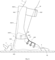
- the present invention is schematically shown in the figure 2 , clothing such as socks and pants has been removed for clarity of representation.
- the connecting device 10 of the lower leg J of a skier S to a ski binding comprises a tibial connection 16, in the form of at least one rigid rod 16-3, the upper end 16-1 of which carries means of fixing 18 to the lower leg and the lower end 16-2 of which carries a pivot connection 20.
- the present invention relates in particular to these fixing means 18 which comprise articulation means 22, with at least one degree of freedom, in translation and in translation and rotation in the best embodiment.
- This arrangement can therefore be adapted to existing shell shoes with tibial connection, simple shoes with tibial connection linked to said simple shoe or even to the embodiment of a preferred footwear assembly with sole as described above.
- the fixing means 18 comprise means 24 for securing to the lower leg J, for example in the form of a collar 26 of the type comprising at least one strip whose ends are provided with self-gripping means. These self-gripping means allow adjustment of the tightening of the securing means by the skier S on the lower leg, this in a known manner.
- the tibial connection 16 comprises at least one rigid rod 16-3, right and left or semi-enveloping, each with an upper end 16-1.
- the articulation means 22 are interposed between each upper end 16-1 of said at least one rigid rod 16-3 and the fixing means 18. In this case, two right and left rods are provided but they could also form only one rigid rod of semi-enveloping shape as already indicated.
- the articulation means 22 comprise at least at least one degree of freedom in translation.
- these articulation means 22 consist of a mushroom-shaped pin 22-1 with a body 22-2 and a head 22-3.
- the pin 22-1 is integral with the securing means 24 to the lower leg J.
- the upper end 16-1 of the rigid rod 16-3 comprises the other part of the articulation means 22, namely a longitudinal slot 16-4. This slot has a width less than the diameter of the head, over at least part of its periphery.
- the body 22-2 of said pin 22-1 slides in this longitudinal slot 16-4 while the head 22-3 of said pin retains said upper end 16-1 of the rigid rod 16-3 of said tibial connection 16.
- the upper end 16-1 of the tibial connection 16 can then pivot and move in translation relative to the securing means 24 which are in no way stressed relative to the lower leg J.
- the securing means 24 of the fixing means 18 of the tibial connection can be placed higher on the lower leg J, that is to say below the knee, in the upper part of the tibia, without inconvenience.
- the higher the positioning of the tibial connection the greater the movements of the fixing means relative to the lower leg.
- the articulation means 22 interposed between the at least one rigid rod 16-3 of the tibial connection 16 and the fixing means 18 of said tibial connection 16 on the lower leg J make it possible to position the securing means 24 between the lower part of the leg base J and the upper part of the lower leg J, therefore preferably in the upper part, this provided that the at least one rigid rod 16-3 is of the appropriate length.
- the advantage of positioning the securing means with at least one rigid rod 16-3 of great length is to provide the skier S with better control of his flexion and the movements of the foot P and to have less significant forces transmitted to the tibia for a given flexion moment due to the increase in the length of the multiplier lever arm.
- a rigid rod 16-3 is provided on each side of the lower leg J so as to have for each shell 14 two rigid rods, right and left, attached to the same fixing means 18 and therefore to the same securing means 24, including when it is a single semi-enveloping rod.
- Articulation means 22, other than a pin in a slide, can be envisaged, including a simple flange in which the upper end of the corresponding rigid rod slides. The flange then being of rectangular section and the end of the rod also being rectangular but of slightly smaller width and sufficiently smaller length, the clearance is sufficient to allow a given translation and angular rotation.
- connecting device 10 finds application to shells with tibial connection of the prior art, to shoes with tibial connection and to the footwear assembly described below.
- the numerous problems related to the presence of a shell with the weight, the constraints on the talus, on the malleolus, the constraints related to the tightening of the shell, the confinement of the foot with the sealing to the evacuation of perspiration, in particular, are not resolved by the connecting device according to the present invention.
- the connecting device according to the present invention can be put in place with the articulation means 22, the present invention proposes a footwear assembly, equipped or not with said connecting device 10, which solves the problems mentioned above and not resolved by the connecting device.
- the footwear assembly 30 comprises a base sole 32 intended to receive a boot 34.
- This base sole 32 comprises at least one lateral lug 32-1, substantially vertical, the end of each lateral lug 32-1 being intended to receive the pivot connection 20 of each rigid upper 16-3.
- each lateral lug 32-1 rises substantially in line with the axis CC' of the ankle of the skier S, having put on the ski, so that the axis AA' coincides with or at least close to the axis CC'.
- This base sole 32 comprises at the front and at the rear ends 32-2 and 32-3 respectively, having a profile conjugated to that of the ski binding F which receives it.
- the foot P is housed in a lightweight shoe 34, itself comprising an upper 34-1 enveloping the foot, for example made of leather comfort, and a rigid sole 34-2.
- the rigid sole 34-2 is advantageously a sole of great stiffness, such as the soles of cycling shoes for automatic pedals.
- This rigid sole 34-2 comprises a first part 36-1 of removable fixing means 36, the second part 36-2 of these removable fixing means 36 of which is carried by the base sole.
- the lightweight shoe 34 can therefore be removably fixed to the base sole 32.
- the removable fixing means 36 can be screws, snap-on fixings, slides or any similar means, at the front and rear of the sole.
- the foot P is held in the lightweight shoe by any known means of closing the upper, such as laces, micrometric closures with wires or even hook closures.
- the footwear assembly 30 therefore comprises a base sole 32 comprising, in the preferred embodiment, two lateral ears 32-1, right and left, a tibial connection 16 with two rigid rods 16-3, right and left, connected together or being a single monolithic rigid rod in a semi-enveloping shape.
- Each rigid rod 16-3 is articulated at the lower part 16-2 around its own pivoting connection 20, right and left, defining the axis AA'.
- Each rigid rod 16-3 is connected by its upper end 16-1, right and left to the fixing means 18 and more particularly to the articulation means 22 of the securing means 24 of said fixing means 18 to the lower leg J.
- the present footwear assembly 30 is completed by at least one waterproof envelope 38, of tubular shape with a barrel 38-1, a lower opening 38-2 and an upper opening 38-3.
- the material used is preferably a waterproof fabric.
- the barrel 38-1 can be made in shape, that is to say with the profile of the light shoe and the lower leg J.
- the lower opening 38-2 has a profile adapted to the peripheral shape of the base sole 32 in order to be able to ensure a mechanical and waterproof connection between said lower opening 38-2 and said base sole 32.
- the upper opening 38-3 can be linked to the fixing means 18, in particular to the securing means 24.
- An opening for putting on the shoe for example a rear opening of the zipper type, can be provided, more particularly along a vertical longitudinal line. This zipper can advantageously be waterproof.
- An opening on the front is also possible.
- This footwear assembly can also be equipped with an insulating layer 39, shown very partially in the figure 2 , which can be a fixed lining by gluing or removable from the waterproof envelope 38 or a separate envelope.
- This insulating layer 39 provides thermal insulation.
- the skier therefore wears a lightweight boot attached and secured to the base sole 32.
- the fixing means 18 at the lower leg J, secured to said base sole in part lower, articulated by means of the pivot links 20, in the lower part, ensure the control of the base sole 32, this protected from external humidity and cold.
- the forces are thus exerted on the base sole 32 and not on the sides of the boot when the rigid uppers are attached to it.
- the flexion can be limited angularly in particular by the stroke of the articulation means 22, so that angular stops, front and rear, can be positioned on the ears for example.
- the choice of the stroke is linked to the physiological possibilities and the pleasure of the practice. This makes it possible to improve the control of the ski by the skier.
- shock absorber means 40 interposed between the base sole 32 and at least one of the rigid rods 16-3 of the connecting means 16.
- shock absorber means 40 can take any form, in particular that of a mechanical spring cylinder housed in two cylindrical half-bodies capable of sliding coaxially, but can also be more sophisticated such as a gas cylinder, an oil cylinder, a mixed cylinder or a coupling of two cylinders. The forces are significant due to the lever arms involved.
- shock absorber means make it possible to further improve the skier's control of the skis during practice and in particular during the descent.
- the shock absorber means can also be disengaged during prolonged stops in downhill skiing or during the ascent with touring skis. During the descent, in both disciplines, the shock absorber means are in service for good control. The clutch is released without tools. According to a particular arrangement, the shock absorber cylinder could also be placed on the front. Similarly, instead of two rigid rods, right and left, a single rigid hemi-enveloping rod would be completely equivalent and this rigid hemi-enveloping rod could come on the front and not on the rear.
- the axis 20-1 of the pivot connection 20 is mounted on coincidence adjustment means 42 of the eccentric type 20-2, see figure 4 . If an adjustment is desired to ensure an even more perfect coincidence, a double eccentric assembly allows an adjustment in the plane. Thus, by rotating the eccentric in its ring, it is already possible to adjust the position of the axis 20-1 of the pivot connection, which further improves comfort by virtually eliminating the movements of the articulation means 22 by coincidence of the axes AA' and CC'.
- the articulation means 22 could be put in place with very limited amplitudes in the footwear assembly 30 according to the present invention.
- the footwear assembly 30 of the present invention makes it possible to maintain free visual and contact access to the ankle and therefore to be able to ensure the adjustment in an optimized manner relative to the morphology of the skier to achieve an almost perfect coincidence, especially with a double eccentric.
- locking means ensure the maintenance of the eccentric or double eccentric in the determined angular position.
- a variant of the coincidence adjustment means 42 of the axis AA' with the axis of rotation of the ankle CC' is visible on the figure 5 .
- This variant includes 20-4 lights crossed at 90°, is another possibility of adjustment.
- a plate 20-5 carries the axis 20-1 of the pivot connection and a set of 20-4 lights and the ear 32-1 carries another set of 20-4 lights crossed at 90°, allows an adjustment of the position of the axis 20-1 of said pivot connection 20 to obtain the desired coincidence.
- This arrangement corresponds to the possibilities of movement of the double eccentric of the previous variant, without these arrangements being limiting.
- the connecting device 50 comprises a tibial connection 51 comprising a rigid semi-enveloping part 51-1 intended to surround the back of the skier's calf and provided, in the upper part, with two left and right rods 51-2, 51-3 intended to come on either side of the calf, and in the lower part, with two left and right straps 51-4 and 51-5 connected together by a transverse connection 51-6 intended to come above the skier's foot.
- a tibial connection 51 comprising a rigid semi-enveloping part 51-1 intended to surround the back of the skier's calf and provided, in the upper part, with two left and right rods 51-2, 51-3 intended to come on either side of the calf, and in the lower part, with two left and right straps 51-4 and 51-5 connected together by a transverse connection 51-6 intended to come above the skier's foot.
- the connecting device 50 comprises means 52 for fixing to the lower leg comprising on the one hand securing means 52-1 intended to be fixed isostatically to the skier's leg.
- the securing means 52-1 may comprise at least one elastic band or a Velcro system for ensuring this isostatism.
- the fixing means 52 also comprise a semi-enveloping part 52-2 intended to surround the front of the skier's tibia, on which the securing means 52-1 are fixed.
- Two left and right straps 52-3 and 52-4 are attached to lateral ends of this part 52-2.
- a slot is provided in each left and right strap 52-3 and 52-4, the upper end of the left, respectively right rod 51-2, 51-3 sliding in this slot.
- each of the flanges 52-3, 52-4 is greater than that of the rod 51-2, 51-3 which slides therein, so that each pair of flange and rod forms an articulation means 53 of the fixing means 52 with respect to the tibial connection 51, which comprises a degree of freedom in translation and a degree of freedom in rotation.
- the securing means 52-1 being isostatic with respect to the leg, the tibial connection 51 and the connecting device 50 are also isostatic with respect to the leg.
- the articulation means 53 only transmits forces perpendicular to the tibia, due to the free translation of the fixing means 52 in a direction parallel to the tibia, which are distributed homogeneously on the leg, due to the free rotation of the fixing means 52 with respect to the tibial connection 51. It would be possible, as a variant, to replace each flange with a slide in which slides a rail mounted on the corresponding rigid rod, the slide and the rail then forming a means of articulation comprising only one degree of freedom in translation.
- the footwear assembly 60 comprises a base sole 61, from which two left and right lateral ears 61-1 and 61-2 extend.
- the ears 61-1, 61-2 extend from a substantially central point of the base sole 61, and obliquely and towards the front of the base sole. It could, as a variant, be envisaged that the ears 61-1, 62-2 extend from an off-center point of the base sole 61 and vertically.
- a loop 61-3 extends from the base sole 61 and rearwardly, so as to be able to surround the skier's heel.
- the lateral ends of the loop 61-3 and the lower ends of the ears 61-1, 61-2 are merged.
- the connecting device 50 comprises a hinge 54, mounted on the transverse connection 51-6, and having two left and right lateral legs 54-1 and 54-2. Each leg 54-1, 54-2 is thus connected to one of the ears 61-1, 61-2 to form a pivot connection 55 of the tibial connection 51 with respect to the base sole 61, the pivot connections 55 thus defining an axis AA'.
- the footwear assembly 60 may include shock-absorbing means 40 interposed between the tibial connection 51 and the base sole 61.
- a first hinge 51-6 is mounted on the part 51-1 and a second hinge 61-4 is mounted on the loop 61-3, the damping means 40 comprising a spring cylinder whose cylinder and piston are each connected to one of these hinges 61-6 and 61-4.
- the axis AA' is substantially offset relative to the axis of rotation CC' of the skier's ankle, being positioned above the talus of the skier's foot.
- This geometry makes it possible to ensure a distribution of the points of force, defined by the articulation means 53, the pivot connections 55, and the two hinges 51-6 and 64-4, relatively balanced around the axis of rotation CC', the lever arms at each of these points of force thus being of the same order of magnitude and the forces at these points being consequently homogeneous.
- the invention makes it possible to dissociate the mechanical, thermal insulation and sealing functions, by distributing them over different elements each dedicated to one or more of these functions. While these functions are generally all provided by the assembly of the rigid shell and the foam of a conventional ski boot, which poses the problems mentioned in the preamble to the description, the invention proposes to assign the mechanical function to the connecting device alone and to assign the thermal insulation and sealing functions to the envelope, and thus to specifically address each of these functions without impacting or interfering with the others.
Landscapes
- Health & Medical Sciences (AREA)
- General Health & Medical Sciences (AREA)
- Physical Education & Sports Medicine (AREA)
- Footwear And Its Accessory, Manufacturing Method And Apparatuses (AREA)
Claims (10)
- Vorrichtung für eine Verbindung zwischen dem Unterschenkel (J) eines Skifahrers (S) mit einem Fuß (P) und einer Knöchelachse (CC'), auf einer Skibindung (F), die auf einem Skibrett (PS) montiert ist, umfassend eine Schuhanordnung (30, 60), eine Schienbeinverbindung (16, 51) mit mindestens einem starren Stab (16-3, 51-2, 51-3), der mindestens eine starre Stab umfassend ein oberes Ende (16-1), das Mittel (18, 52) für die Bindung an den Unterschenkel (J) besitzt, einschließlich Sicherungsmitteln (24, 52-1), und ein unteres Ende (16-2), das einen Verbindungszapfen (20, 55) entlang einer Achse AA' relativ zu der Schuhanordnung (30, 60) aufweist, die Gelenkmittel (22, 53) aufweist, die mindestens einen Freiheitsgrad vorweisen, die zwischen dem oberen Ende (16-1) des mindestens einen starren Stabs (16-3, 51-2, 51-3) und den Mitteln (18, 52) für die Bindung an den Unterschenkel (J) eingefügt sind,
dadurch gekennzeichnet, dass die Gelenkmittel (22, 53) einen Translationsfreiheitsgrad umfassen. - Verbindungsvorrichtung zwischen dem Unterschenkel (J) eines Skifahrers (S) und einer Skibindung (F), die auf einem Skibrett (PS) montiert ist, nach Anspruch 1, dadurch gekennzeichnet, dass die Gelenkmittel (22, 53) einen Translationsfreiheitsgrad und einen Rotationsfreiheitsgrad umfassen.
- Verbindungsvorrichtung zwischen dem Unterschenkel (J) eines Skifahrers (S) und einer Skibindung (F), die auf einem Skibrett (PS) montiert ist, nach einem der vorstehenden Ansprüche, dadurch gekennzeichnet, dass die Gelenkmittel (22) einen pilzförmigen Stift (22-1) mit einem Körper (22-2) und einem Kopf (22-3) umfassen, der mit dem Sicherungsmittel (24) an dem Unterschenkel (J) fest verbunden ist, und einen Längsschlitz (16-4) umfassen, der an dem oberen Ende (16-1) des starren Stabs (16-3) vorgesehen ist, durch den der Körper des Stifts verläuft, wobei dieser Schlitz eine Breite besitzt, die kleiner als der Durchmesser des Kopfs ist, sodass der Körper (22-2) des Stifts (22-1) in diesem Längsschlitz (16-4) gleitet, wohingegen der Kopf (22-3) des Stifts das obere Ende (16-1) des starren Stabs (16-3) der Schienbeinverbindung (16) hält.
- Schuhanordnung (30, 60), die mit der Verbindungsvorrichtung (10) zwischen dem Unterschenkel (J) eines Skifahrers (S) und einer Skibindung (F) ausgerüstet ist, die auf einem Skibrett (PS) montiert ist, nach einem der Ansprüche 1 bis 3, dadurch gekennzeichnet, dass sie eine Basissohle (32, 61) umfasst, die dazu bestimmt, ist, einen Schuh (34) aufzunehmen, wobei die Basissohle (32, 61) mindestens einen seitlichen Lappen (32-1, 61-1, 61-2) aufweist, im Wesentlichen vertikal, wobei das Ende jedes seitlichen Lappens (32-1, 61-1, 61-2) dazu bestimmt ist, die Schwenkverbindung (20, 55) jedes starren Stabs (16-3, 51-2, 51-3) aufzunehmen.
- Schuhanordnung (30) nach Anspruch 4, dadurch gekennzeichnet, dass das Ende jedes seitlichen Lappens (32-1) im Wesentlichen an der Achse (CC') des Knöchels des Skifahrers (S) steigt, so dass die Achse (AA') der Schwenkverbindung (55) mindestens nahe an der Achse (CC') des Knöchels (S) des Skifahrers liegt.
- Schuhanordnung (60) nach Anspruch 4, dadurch gekennzeichnet, dass sich jeder seitliche Lappen (61-1, 61-2) so erstreckt, dass die Achse (AA') der Schwenkverbindung (55) relativ zu der Achse (CC') des Knöchels im Wesentlichen versetzt ist.
- Schuhanordnung (30, 60) nach Anspruch 4 bis 6,
dadurch gekennzeichnet, dass die Basissohle (32, 61) vorne und hinten Enden (32-2) beziehungsweise (32-3) aufweist, die ein Profil besitzen, das mit dem der Skibindung (F) in Einklang ist. - Schuhanordnung (30, 60) nach Anspruch 4 bis 7,
dadurch gekennzeichnet, dass der Schuh (34) eine starre Sohle (34-2) umfasst, die mit einem ersten Teil (36-1) von abnehmbaren Bindungsmitteln (36) versehen ist, wobei der zweite Teil (36-2) dieser abnehmbaren Bindungsmittel (36) durch die Basissohle (32, 61) getragen wird. - Schuhanordnung (30, 60) nach einem der Ansprüche 4 bis 8,
dadurch gekennzeichnet, dass sie mindestens eine röhrenförmige undurchlässige Hülle (38) mit einem Schaft (38-1), einer unteren Öffnung (38-2), einer oberen Öffnung (38-3) und einer Öffnung für das Anziehen umfasst. - Schuhanordnung (30) nach einem der Ansprüche 4 bis 9,
dadurch gekennzeichnet, dass sie Mittel (42) zum Einstellen eines Zusammentreffens der Achse (AA') der Schwenkverbindung (55) mit der Rotationsachse (CC') des Knöchels des Skifahrers (S) umfasst.
Applications Claiming Priority (3)
| Application Number | Priority Date | Filing Date | Title |
|---|---|---|---|
| FR2003773A FR3109279B1 (fr) | 2020-04-15 | 2020-04-15 | Dispositif de liaison de la basse jambe d'un skieur avec une fixation de ski, ensemble chaussant integrant ledit dispositif |
| FR2003775A FR3109278B1 (fr) | 2020-04-15 | 2020-04-15 | Ensemble chaussant integrant un dispositif de liaison de la basse jambe d'un skieur avec une fixation de ski |
| PCT/EP2021/059420 WO2021209376A1 (fr) | 2020-04-15 | 2021-04-12 | Dispositif de liaison de la basse jambe d'un skieur avec une fixation de ski, ensemble chaussant integrant ledit dispositif |
Publications (3)
| Publication Number | Publication Date |
|---|---|
| EP4135548A1 EP4135548A1 (de) | 2023-02-22 |
| EP4135548B1 true EP4135548B1 (de) | 2024-09-04 |
| EP4135548C0 EP4135548C0 (de) | 2024-09-04 |
Family
ID=75728780
Family Applications (1)
| Application Number | Title | Priority Date | Filing Date |
|---|---|---|---|
| EP21722107.6A Active EP4135548B1 (de) | 2020-04-15 | 2021-04-12 | Vorrichtung zum verbinden des unterschenkels eines skifahrers mit einer skibindung und schuhaufbau mit einer solchen vorrichtung |
Country Status (5)
| Country | Link |
|---|---|
| US (1) | US12396514B2 (de) |
| EP (1) | EP4135548B1 (de) |
| JP (1) | JP7692434B2 (de) |
| CN (1) | CN115605109A (de) |
| WO (1) | WO2021209376A1 (de) |
Families Citing this family (1)
| Publication number | Priority date | Publication date | Assignee | Title |
|---|---|---|---|---|
| FR3131509B1 (fr) * | 2022-01-06 | 2025-05-02 | K2I | Chaussure de ski avec pièce levier arrière |
Family Cites Families (20)
| Publication number | Priority date | Publication date | Assignee | Title |
|---|---|---|---|---|
| CH505630A (de) | 1969-11-10 | 1971-04-15 | Gertsch Ernst | Sicherheits-Skibindung |
| US3747235A (en) * | 1972-08-29 | 1973-07-24 | D Post | Lever-type ski boots |
| AT325485B (de) | 1973-06-07 | 1975-10-27 | Smolka & Co Wiener Metall | Auslöseskibindung |
| ATA725375A (de) * | 1974-10-01 | 1977-08-15 | Willi Hans Anton | Beinstutze zum abstutzen des unterschenkels eines skifahrers |
| FR2462116A1 (fr) * | 1979-07-27 | 1981-02-13 | Baumann Peter | Chaussure de ski |
| US4367885A (en) * | 1980-04-11 | 1983-01-11 | Alpine Research, Inc. | Ski binding |
| FR2497639A1 (fr) * | 1981-01-09 | 1982-07-16 | Salomon & Fils F | Dispositif de controle de l'appui avant de la tige d'une chaussure de ski |
| US4473235A (en) * | 1982-01-19 | 1984-09-25 | Burt Lionel J | Apparatus for improved control of skis |
| FR2527908A1 (fr) * | 1982-06-02 | 1983-12-09 | Salomon & Fils F | Dispositif de reglage d'une chaussure de ski |
| DE4139527C2 (de) * | 1991-02-12 | 1995-07-13 | Raimund W Vogel | Skischuh |
| ATE126974T1 (de) * | 1991-03-21 | 1995-09-15 | Helmut Girardelli | Skischuh. |
| WO1994027455A1 (de) * | 1993-05-21 | 1994-12-08 | Helmut Girardelli | Skischuh |
| FR2745988B1 (fr) * | 1996-03-15 | 1998-09-04 | Chaussures de sport guidees par des jambieres et dispositif de freinage adapte | |
| FR2750875B1 (fr) * | 1996-07-11 | 1998-09-11 | Rossignol Sa | Ensemble chaussure-ski equipe de moyens destines a modifier la raideur et/ou le cambre du ski en fonction de l'inclinaison du collier par rapport a la coque de la chaussure |
| CA2209836C (en) * | 1997-08-12 | 2001-03-27 | Johan G. F. Heuvel | Ski boot |
| US6663118B1 (en) * | 1998-12-02 | 2003-12-16 | Shimano, Inc. | Snowboard interface with an upper portion that translates and rotates relative to a lower portion |
| FR2793660B1 (fr) * | 1999-05-17 | 2001-08-10 | Jean Francois Couturier | Chaussure de sport, notamment de ski alpin, de randonnee, de fond, de surf des neiges, de patin a roulettes ou de patin a glace |
| KR200358899Y1 (ko) * | 2004-05-14 | 2004-08-12 | 김준 | 스노우 보드용 바인딩 |
| AT503543B1 (de) * | 2006-07-18 | 2007-11-15 | Barthel Fritz | Sportschuh |
| EP2163226A1 (de) * | 2007-04-23 | 2010-03-17 | Golden Crab, S.L. | Exoskelett zur sicherheit und kontrolle beim schifahren |
-
2021
- 2021-04-12 US US17/918,785 patent/US12396514B2/en active Active
- 2021-04-12 CN CN202180035485.6A patent/CN115605109A/zh active Pending
- 2021-04-12 JP JP2022562718A patent/JP7692434B2/ja active Active
- 2021-04-12 WO PCT/EP2021/059420 patent/WO2021209376A1/fr not_active Ceased
- 2021-04-12 EP EP21722107.6A patent/EP4135548B1/de active Active
Also Published As
| Publication number | Publication date |
|---|---|
| US12396514B2 (en) | 2025-08-26 |
| US20230143847A1 (en) | 2023-05-11 |
| EP4135548A1 (de) | 2023-02-22 |
| EP4135548C0 (de) | 2024-09-04 |
| WO2021209376A1 (fr) | 2021-10-21 |
| JP7692434B2 (ja) | 2025-06-13 |
| CN115605109A (zh) | 2023-01-13 |
| JP2023521239A (ja) | 2023-05-23 |
Similar Documents
| Publication | Publication Date | Title |
|---|---|---|
| EP0644730B1 (de) | Ski- oder schlittschuh | |
| EP1174048B1 (de) | Spannvorrichtung für Schuhwerk | |
| EP1166668B1 (de) | Sportschuh mit einer an einer flexiblen Fersenkappe befestigten steifen Fersenkappe | |
| EP1040768A1 (de) | Sportschuh mit weicher Versteifungsstruktur | |
| EP3165113B1 (de) | Sportstiefel | |
| EP0740908A1 (de) | Schuh zum Betreiben eines Wintersports | |
| FR2793660A1 (fr) | Chaussure de sport, notamment de ski alpin, de randonnee, de fond, de surf des neiges, de patin a roulettes ou de patin a glace | |
| EP0774218B1 (de) | Rollschuh | |
| EP4135548B1 (de) | Vorrichtung zum verbinden des unterschenkels eines skifahrers mit einer skibindung und schuhaufbau mit einer solchen vorrichtung | |
| EP0416437A1 (de) | Langlaufskischuh | |
| FR2471755A2 (fr) | Chaussure de sport equipee d'une languette dynamique | |
| EP0521287A1 (de) | Lauf- oder Wanderschuh für Bergtouren mit innerer Spannhalterung | |
| EP0753267B1 (de) | Schneegleitbrett mit einer Innenschale und einem schwenkbaren steifen Hinterteil | |
| FR2740011A1 (fr) | Chaussure a tige ajustable | |
| FR3109279A1 (fr) | Dispositif de liaison de la basse jambe d'un skieur avec une fixation de ski, ensemble chaussant integrant ledit dispositif | |
| FR3109278A1 (fr) | Ensemble chaussant integrant un dispositif de liaison de la basse jambe d'un skieur avec une fixation de ski | |
| CH686754A5 (fr) | Chausson intérieur pour chaussure de ski. | |
| EP1319346B1 (de) | Sportschuh mit variabeler Steifigkeit | |
| WO2003092422A1 (fr) | Patin a roulettes | |
| WO2019116138A1 (fr) | Chaussure de sport sans appui sur la malléole | |
| EP0947144A1 (de) | Sportschuh mit teilweise bedeckter starrer Struktur | |
| EP0941676B1 (de) | Schuh für Gleitsporten | |
| FR3131509A1 (fr) | Chaussure de ski avec pièce levier arrière | |
| FR2764485A1 (fr) | Chaussure de ski | |
| FR2769799A1 (fr) | Chaussure pour sport de glisse, en particulier chaussure de ski |
Legal Events
| Date | Code | Title | Description |
|---|---|---|---|
| STAA | Information on the status of an ep patent application or granted ep patent |
Free format text: STATUS: UNKNOWN |
|
| STAA | Information on the status of an ep patent application or granted ep patent |
Free format text: STATUS: THE INTERNATIONAL PUBLICATION HAS BEEN MADE |
|
| PUAI | Public reference made under article 153(3) epc to a published international application that has entered the european phase |
Free format text: ORIGINAL CODE: 0009012 |
|
| STAA | Information on the status of an ep patent application or granted ep patent |
Free format text: STATUS: REQUEST FOR EXAMINATION WAS MADE |
|
| 17P | Request for examination filed |
Effective date: 20221006 |
|
| AK | Designated contracting states |
Kind code of ref document: A1 Designated state(s): AL AT BE BG CH CY CZ DE DK EE ES FI FR GB GR HR HU IE IS IT LI LT LU LV MC MK MT NL NO PL PT RO RS SE SI SK SM TR |
|
| DAV | Request for validation of the european patent (deleted) | ||
| DAX | Request for extension of the european patent (deleted) | ||
| GRAP | Despatch of communication of intention to grant a patent |
Free format text: ORIGINAL CODE: EPIDOSNIGR1 |
|
| STAA | Information on the status of an ep patent application or granted ep patent |
Free format text: STATUS: GRANT OF PATENT IS INTENDED |
|
| INTG | Intention to grant announced |
Effective date: 20240328 |
|
| GRAS | Grant fee paid |
Free format text: ORIGINAL CODE: EPIDOSNIGR3 |
|
| GRAA | (expected) grant |
Free format text: ORIGINAL CODE: 0009210 |
|
| STAA | Information on the status of an ep patent application or granted ep patent |
Free format text: STATUS: THE PATENT HAS BEEN GRANTED |
|
| AK | Designated contracting states |
Kind code of ref document: B1 Designated state(s): AL AT BE BG CH CY CZ DE DK EE ES FI FR GB GR HR HU IE IS IT LI LT LU LV MC MK MT NL NO PL PT RO RS SE SI SK SM TR |
|
| REG | Reference to a national code |
Ref country code: GB Ref legal event code: FG4D Free format text: NOT ENGLISH |
|
| REG | Reference to a national code |
Ref country code: CH Ref legal event code: EP |
|
| REG | Reference to a national code |
Ref country code: IE Ref legal event code: FG4D Free format text: LANGUAGE OF EP DOCUMENT: FRENCH |
|
| REG | Reference to a national code |
Ref country code: DE Ref legal event code: R096 Ref document number: 602021018309 Country of ref document: DE |
|
| U01 | Request for unitary effect filed |
Effective date: 20241003 |
|
| U07 | Unitary effect registered |
Designated state(s): AT BE BG DE DK EE FI FR IT LT LU LV MT NL PT RO SE SI Effective date: 20241025 |
|
| PG25 | Lapsed in a contracting state [announced via postgrant information from national office to epo] |
Ref country code: NO Free format text: LAPSE BECAUSE OF FAILURE TO SUBMIT A TRANSLATION OF THE DESCRIPTION OR TO PAY THE FEE WITHIN THE PRESCRIBED TIME-LIMIT Effective date: 20241204 |
|
| PG25 | Lapsed in a contracting state [announced via postgrant information from national office to epo] |
Ref country code: GR Free format text: LAPSE BECAUSE OF FAILURE TO SUBMIT A TRANSLATION OF THE DESCRIPTION OR TO PAY THE FEE WITHIN THE PRESCRIBED TIME-LIMIT Effective date: 20241205 Ref country code: PL Free format text: LAPSE BECAUSE OF FAILURE TO SUBMIT A TRANSLATION OF THE DESCRIPTION OR TO PAY THE FEE WITHIN THE PRESCRIBED TIME-LIMIT Effective date: 20240904 |
|
| PG25 | Lapsed in a contracting state [announced via postgrant information from national office to epo] |
Ref country code: HR Free format text: LAPSE BECAUSE OF FAILURE TO SUBMIT A TRANSLATION OF THE DESCRIPTION OR TO PAY THE FEE WITHIN THE PRESCRIBED TIME-LIMIT Effective date: 20240904 |
|
| PG25 | Lapsed in a contracting state [announced via postgrant information from national office to epo] |
Ref country code: ES Free format text: LAPSE BECAUSE OF FAILURE TO SUBMIT A TRANSLATION OF THE DESCRIPTION OR TO PAY THE FEE WITHIN THE PRESCRIBED TIME-LIMIT Effective date: 20240904 Ref country code: RS Free format text: LAPSE BECAUSE OF FAILURE TO SUBMIT A TRANSLATION OF THE DESCRIPTION OR TO PAY THE FEE WITHIN THE PRESCRIBED TIME-LIMIT Effective date: 20241204 |
|
| PG25 | Lapsed in a contracting state [announced via postgrant information from national office to epo] |
Ref country code: RS Free format text: LAPSE BECAUSE OF FAILURE TO SUBMIT A TRANSLATION OF THE DESCRIPTION OR TO PAY THE FEE WITHIN THE PRESCRIBED TIME-LIMIT Effective date: 20241204 Ref country code: PL Free format text: LAPSE BECAUSE OF FAILURE TO SUBMIT A TRANSLATION OF THE DESCRIPTION OR TO PAY THE FEE WITHIN THE PRESCRIBED TIME-LIMIT Effective date: 20240904 Ref country code: NO Free format text: LAPSE BECAUSE OF FAILURE TO SUBMIT A TRANSLATION OF THE DESCRIPTION OR TO PAY THE FEE WITHIN THE PRESCRIBED TIME-LIMIT Effective date: 20241204 Ref country code: HR Free format text: LAPSE BECAUSE OF FAILURE TO SUBMIT A TRANSLATION OF THE DESCRIPTION OR TO PAY THE FEE WITHIN THE PRESCRIBED TIME-LIMIT Effective date: 20240904 Ref country code: GR Free format text: LAPSE BECAUSE OF FAILURE TO SUBMIT A TRANSLATION OF THE DESCRIPTION OR TO PAY THE FEE WITHIN THE PRESCRIBED TIME-LIMIT Effective date: 20241205 Ref country code: ES Free format text: LAPSE BECAUSE OF FAILURE TO SUBMIT A TRANSLATION OF THE DESCRIPTION OR TO PAY THE FEE WITHIN THE PRESCRIBED TIME-LIMIT Effective date: 20240904 |
|
| PG25 | Lapsed in a contracting state [announced via postgrant information from national office to epo] |
Ref country code: IS Free format text: LAPSE BECAUSE OF FAILURE TO SUBMIT A TRANSLATION OF THE DESCRIPTION OR TO PAY THE FEE WITHIN THE PRESCRIBED TIME-LIMIT Effective date: 20250104 |
|
| PG25 | Lapsed in a contracting state [announced via postgrant information from national office to epo] |
Ref country code: SM Free format text: LAPSE BECAUSE OF FAILURE TO SUBMIT A TRANSLATION OF THE DESCRIPTION OR TO PAY THE FEE WITHIN THE PRESCRIBED TIME-LIMIT Effective date: 20240904 |
|
| PG25 | Lapsed in a contracting state [announced via postgrant information from national office to epo] |
Ref country code: CZ Free format text: LAPSE BECAUSE OF FAILURE TO SUBMIT A TRANSLATION OF THE DESCRIPTION OR TO PAY THE FEE WITHIN THE PRESCRIBED TIME-LIMIT Effective date: 20240904 |
|
| PG25 | Lapsed in a contracting state [announced via postgrant information from national office to epo] |
Ref country code: SK Free format text: LAPSE BECAUSE OF FAILURE TO SUBMIT A TRANSLATION OF THE DESCRIPTION OR TO PAY THE FEE WITHIN THE PRESCRIBED TIME-LIMIT Effective date: 20240904 |
|
| U20 | Renewal fee for the european patent with unitary effect paid |
Year of fee payment: 5 Effective date: 20250409 |
|
| PGFP | Annual fee paid to national office [announced via postgrant information from national office to epo] |
Ref country code: GB Payment date: 20250423 Year of fee payment: 5 |
|
| PLBE | No opposition filed within time limit |
Free format text: ORIGINAL CODE: 0009261 |
|
| STAA | Information on the status of an ep patent application or granted ep patent |
Free format text: STATUS: NO OPPOSITION FILED WITHIN TIME LIMIT |
|
| PGFP | Annual fee paid to national office [announced via postgrant information from national office to epo] |
Ref country code: CH Payment date: 20250501 Year of fee payment: 5 |
|
| 26N | No opposition filed |
Effective date: 20250605 |
|
| PG25 | Lapsed in a contracting state [announced via postgrant information from national office to epo] |
Ref country code: MC Free format text: LAPSE BECAUSE OF FAILURE TO SUBMIT A TRANSLATION OF THE DESCRIPTION OR TO PAY THE FEE WITHIN THE PRESCRIBED TIME-LIMIT Effective date: 20240904 |