EP4135555B1 - Pièce de support, kit de meubles, meuble et utilisation correspondante - Google Patents
Pièce de support, kit de meubles, meuble et utilisation correspondante Download PDFInfo
- Publication number
- EP4135555B1 EP4135555B1 EP20719408.5A EP20719408A EP4135555B1 EP 4135555 B1 EP4135555 B1 EP 4135555B1 EP 20719408 A EP20719408 A EP 20719408A EP 4135555 B1 EP4135555 B1 EP 4135555B1
- Authority
- EP
- European Patent Office
- Prior art keywords
- support part
- furniture
- piece
- valve
- liquid outlet
- Prior art date
- Legal status (The legal status is an assumption and is not a legal conclusion. Google has not performed a legal analysis and makes no representation as to the accuracy of the status listed.)
- Active
Links
Images

Classifications
-
- A—HUMAN NECESSITIES
- A47—FURNITURE; DOMESTIC ARTICLES OR APPLIANCES; COFFEE MILLS; SPICE MILLS; SUCTION CLEANERS IN GENERAL
- A47B—TABLES; DESKS; OFFICE FURNITURE; CABINETS; DRAWERS; GENERAL DETAILS OF FURNITURE
- A47B77/00—Kitchen cabinets
- A47B77/04—Provision for particular uses of compartments or other parts ; Compartments moving up and down, revolving parts
- A47B77/06—Provision for particular uses of compartments or other parts ; Compartments moving up and down, revolving parts for incorporating sinks, with or without draining boards, splash-backs, or the like
-
- E—FIXED CONSTRUCTIONS
- E03—WATER SUPPLY; SEWERAGE
- E03C—DOMESTIC PLUMBING INSTALLATIONS FOR FRESH WATER OR WASTE WATER; SINKS
- E03C1/00—Domestic plumbing installations for fresh water or waste water; Sinks
- E03C1/02—Plumbing installations for fresh water
- E03C1/04—Water-basin installations specially adapted to wash-basins or baths
- E03C1/0401—Fixing a tap to the sanitary appliance or to an associated mounting surface, e.g. a countertop
-
- A—HUMAN NECESSITIES
- A47—FURNITURE; DOMESTIC ARTICLES OR APPLIANCES; COFFEE MILLS; SPICE MILLS; SUCTION CLEANERS IN GENERAL
- A47B—TABLES; DESKS; OFFICE FURNITURE; CABINETS; DRAWERS; GENERAL DETAILS OF FURNITURE
- A47B57/00—Cabinets, racks or shelf units, characterised by features for adjusting shelves or partitions
- A47B57/30—Cabinets, racks or shelf units, characterised by features for adjusting shelves or partitions with means for adjusting the height of detachable shelf supports
-
- A—HUMAN NECESSITIES
- A47—FURNITURE; DOMESTIC ARTICLES OR APPLIANCES; COFFEE MILLS; SPICE MILLS; SUCTION CLEANERS IN GENERAL
- A47B—TABLES; DESKS; OFFICE FURNITURE; CABINETS; DRAWERS; GENERAL DETAILS OF FURNITURE
- A47B96/00—Details of cabinets, racks or shelf units not covered by a single one of groups A47B43/00 - A47B95/00; General details of furniture
- A47B96/02—Shelves
- A47B96/024—Shelves characterised by support bracket location means, e.g. fixing means between support bracket and shelf
-
- E—FIXED CONSTRUCTIONS
- E03—WATER SUPPLY; SEWERAGE
- E03C—DOMESTIC PLUMBING INSTALLATIONS FOR FRESH WATER OR WASTE WATER; SINKS
- E03C1/00—Domestic plumbing installations for fresh water or waste water; Sinks
- E03C1/02—Plumbing installations for fresh water
- E03C1/021—Devices for positioning or connecting of water supply lines
-
- A—HUMAN NECESSITIES
- A47—FURNITURE; DOMESTIC ARTICLES OR APPLIANCES; COFFEE MILLS; SPICE MILLS; SUCTION CLEANERS IN GENERAL
- A47B—TABLES; DESKS; OFFICE FURNITURE; CABINETS; DRAWERS; GENERAL DETAILS OF FURNITURE
- A47B2220/00—General furniture construction, e.g. fittings
- A47B2220/03—Combined cabinets and wash basins
Definitions
- the invention relates to a support part in the form of a shelf for a piece of furniture.
- Such support parts are known, for example, as shelf boards in system furniture and other pieces of furniture, in particular cabinets or shelves.
- the invention further relates to a furniture construction kit and a piece of furniture.
- the medicine cabinet for mounting on a wall above a wash basin is previously known.
- the medicine cabinet comprises a cabinet frame and a door which is pivotally mounted on the front of the cabinet frame.
- a mirror is mounted on the outer surface of the door and has an opening there.
- a discharge channel extends through the opening in the mirror and allows a jet of water to be discharged.
- the features of claim 1 are provided according to the invention.
- the carrier part has a liquid outlet which is arranged at least indirectly on an outer side of the carrier part, in particular, it is attached to the outside.
- the outside, on which the liquid outlet can be arranged and in particular attached can be, for example, a top side, a bottom side or also a transverse side of the carrier part.
- the liquid outlet can be arranged, in particular fastened, for example by means of a holder on the outside of the carrier part.
- the holder can have a fastening interface and/or a receptacle.
- the holder can be easily fastened to the carrier part via the fastening interface.
- the liquid outlet can be arranged in the receptacle of the holder.
- the liquid outlet is arranged completely outside an imaginary envelope of the carrier part.
- the liquid outlet can thus be arranged as a separate part on an outer side of the carrier part, for example a shelf, and fastened to this outer side without providing a recess or depression for receiving the liquid outlet in the carrier part. In this way, any carrier parts can be provided with a liquid outlet without prior adjustments.
- the support part is designed in the shape of a plate. This makes it possible to achieve a compact design in which the piece of furniture does not have to have large dimensions after being equipped with a water-conducting functionality according to the invention.
- the invention has recognized that the at least one connection line and the liquid outlet can be easily arranged, in particular attached, to a plate-shaped structure.
- the support part is designed as a shelf. This means that the liquid outlet can be positioned flexibly.
- an actuating mechanism for a valve that blocks or releases at least one connecting line can be arranged on the piece of furniture. This makes it easy to open and close the liquid outlet.
- the actuating mechanism can be arranged on the support part.
- the advantage here is that a functional unit can be provided that can be easily retrofitted or installed without specific specialist knowledge of the water connection being required.
- the valve can also be designed as a temperature-dependent switching valve and/or as a mixing valve.
- the support part can be made of wood and/or wood fibers or at least coated with wood on the outside or made of wood. This opens up interesting design options, for example in the kitchen and bathroom area.
- the support part can be made of a composite material, in particular WPC (wood-plastic composite, wood-polymer composite).
- the carrier part can also be made of sheet metal, metal, ceramic, acrylic and/or polymer, for example in a sandwich construction, in particular in combination with a wood-containing component.
- the carrier part can also be milled, cast and/or glued together. This makes it possible to create robust furniture.
- the cable routing is arranged between two plates forming the top and bottom.
- the cable routing is formed in a hollow structure, for example a honeycomb structure or a lamella structure.
- the invention makes use of the fact that hollow spaces in a lightweight structure can be used for the at least one connecting cable and accessories.
- At least one control line of the pilot valve is arranged on an outer side of the carrier part or in a control line guide in the carrier part.
- the pilot valve can thus be arranged at a distance from the main valve, for example outside the carrier part.
- several control lines can be provided in order to form a mixing valve.
- control line can thus be attached to the support part without first having to introduce a control line guide into the support part.
- a preferred application provides for a furniture kit with at least one support part according to the invention, in particular as described above and/or according to one of the claims directed to a support part.
- a modular system can also be formed in that, for example, a uniform support part with the water-conducting functionality can be used for different pieces of furniture, for example with different heights.
- the invention thus makes it possible to form a piece of furniture with at least one support part according to the invention, in particular as described above and/or according to one of the claims directed to a support part.
- This enables a space-saving integration of a water-carrying function into pieces of furniture such as bookshelves, and separate washstands and the like are no longer necessary. This can be used to advantage in particular when furnishing a narrowly limited living space.
- the piece of furniture can be provided with a washbasin underneath the support part. This also makes it easy to integrate a drainage system for escaping water into the piece of furniture. A washstand or a sink can thus be easily integrated into a normal piece of furniture.
- the support part can be arranged on the piece of furniture in a height-adjustable manner. This makes it easy to integrate an exit height, for example above a washbasin.
- the piece of furniture can be provided that the valve can be connected to a water outlet via a pipe laid in or behind a wall of the piece of furniture.
- a pipe laid in or behind a wall of the piece of furniture.
- the invention takes advantage of the fact that there is often enough space on the rear wall or in the rear wall to accommodate the pipe.
- the pipe can then be easily led to the floor. From there, it can be connected to a water outlet, for example a corner valve.
- a preferred application provides for the use of a support part according to the invention, in particular as described above and/or according to one of the claims directed to a support part, of a piece of furniture for fastening a water outlet and at least one connecting line.
- a waterproof design of the support part or other parts of the piece of furniture is therefore not necessary.
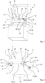
- a connecting line 12 is attached to the underside 5 of the carrier part 1. Both the connecting line 12 and the liquid outlet 9 are arranged completely outside an imaginary envelope of the carrier part 1.
- the liquid outlet 9 is connected to the connecting line 12 for supplying liquid, here water.
- the support part 1 is designed as a shelf 16 which is inserted into a body 17 of the piece of furniture 3.
- the support part 1 is designed as part of the body 17, for example as part of a side wall or a top side or a bottom side or a stabilizing wall between the top side and the bottom side.
- the valve 19 can be connected to the liquid outlet 9 via a flexible hose.
- a section of the connecting line between the valve 19 and the liquid outlet 9 is formed by a pipe 38 which opens into the liquid outlet 9 at its other end.
- Another section of the connecting line 12 is also designed as a rigid pipe 38. This section connects the valve 19 to a line 35 that runs along the back of a rear wall 34 of the piece of furniture 3.
- the at least one connecting line 12 is designed as a flexible hose.
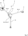
- the valve 19 has a pilot valve 24 with which a main valve 25 of the valve 19 can be controlled.
- the main valve 25 has a membrane which can be controlled with a water pressure applied to the main valve 25 depending on a switching position of the pilot valve 24.
- a control line 26 is formed inside the valve 19, with which water can be guided into or out of a pressure chamber 27, which is delimited by the membrane.
- the control line 26 can be formed as a relief opening in the previously mentioned membrane.
- the at least one control line is designed as a separate control line.
- the pilot valve 24 can be actuated via an actuating element 28 of the actuating mechanism 18.
- Fig. 5 shows the case that the actuating element 28 is mechanically coupled to the pilot valve 24 via a mechanical coupling 29, which comprises a control rod 30.
- the actuating element 28 is coupled to the valve 19 in a different way, for example via a Bowden cable or a gear.
- the actuating element 28 is formed below a front outer side 31 of the carrier part 1. In further embodiments, the actuating element 28 is arranged on the top side, the bottom side and/or another side edge.
- the support part 1 shown and described forms part of a furniture kit, with which, for example, the Figures 1 and 2 shown piece of furniture 3 can be put together.
- Figure 1 shows that a wash basin 32 is arranged below the liquid outlet 9.
- the body 17 has side walls 33 and the previously mentioned rear wall 34. A line 35 is led through the rear wall 34.
- the valve 19 can thus be connected via the line 35 to a water extraction point not shown, for example a fitting or an angle valve.
- the support part 1 can be attached to the body 17 as a shelf 16 at different heights.
- the piece of furniture 3 has a hole in its rear wall 34 at the appropriate position of the shelf 16.
- the rear wall 34 can be composed of several individual parts, for example one individual part being designed with a hole and other individual parts without a hole. By selecting the dimensions of the individual parts accordingly, it is possible to achieve that the hole can be placed in different positions when the individual parts are put together in different ways.
- the rear wall 34 can be designed in two parts with an upper and a lower part, wherein the upper part can be pushed upwards like a roller shutter and the lower part can be pushed downwards like a roller shutter. A dividing line between the parts can thus be moved vertically in order to enable the cable 35 to be led out at the dividing line for all positions of the support part 1.
- the actuating element 28 can be coupled to the valve 19, in particular to the pilot valve 24, via a mechanical coupling 29 or another, for example electronic, coupling.
- the pilot valve 24 can be separated from the main valve 25 and connected to it via a control line 26.
- the pilot valve 24 can be arranged directly on the actuating element 28.
- valve 19 can be arranged in or on the vanity top 36 or in or on the wash basin 32 and connected to the liquid outlet 9 via a long connecting line 12.
- the support part 1 is designed as a base of the body 17, and the piece of furniture 3 is arranged for use above a washbasin or a bath or shower tray.
Landscapes
- Health & Medical Sciences (AREA)
- Life Sciences & Earth Sciences (AREA)
- Engineering & Computer Science (AREA)
- Hydrology & Water Resources (AREA)
- Public Health (AREA)
- Water Supply & Treatment (AREA)
- Sink And Installation For Waste Water (AREA)
- Details Of Rigid Or Semi-Rigid Containers (AREA)
- Assembled Shelves (AREA)
- Furniture Connections (AREA)
Claims (17)
- Pièce portante (1), à savoir planche de rayon (2), pour un meuble (3), laquelle pièce portante (1) comporte un écoulement de liquide (9) qui et disposé, en particulier fixé, au moins indirectement sur une face extérieure (4, 5), en particulier sur une face supérieure (4) ou une face inférieure (5) ou sur une face transversale de la pièce portante (1), caractérisée en ce que la pièce portante (1) comporte une conduite de raccordement (12) vers l'écoulement de liquide (9) qui est au moins en partie disposée sur une face extérieure (4, 5) de la pièce portante (1) et dépasse de celle-ci, et en ce qu'est formé dans la pièce portante (1) un guidage de conduite dans lequel est disposée une partie de la conduite de raccordement (12).
- Pièce portante (1) selon la revendication précédente, dans laquelle l'écoulement de liquide (9) est disposé, en particulier fixé, sur la face extérieure (4, 5) de la pièce portante (1) au moyen d'une fixation (10) et/ou dans laquelle l'écoulement de liquide (9) est entièrement disposé à l'extérieur d'une enveloppante imaginaire de la pièce portante (1).
- Pièce portante (1) selon l'une des revendications précédentes, dans laquelle la conduite de raccordement (12) est disposée, de préférence fixée, au moins en partie sur une face supérieure (4) ou une face inférieure (5) ou sur une face transversale de la pièce portante (1), de préférence sur la même face extérieure que l'écoulement de liquide (9), la conduite de raccordement (12) étant de préférence entièrement disposée à l'extérieur d'une enveloppante imaginaire de la pièce portante (1).
- Pièce portante (1) selon l'une des revendications précédentes, laquelle pièce portante (1) est assemblée de façon amovible à un corps (17) du meuble (3) et/ou disposée de façon mobile sur le ou un corps (17).
- Pièce portante (1) selon l'une des revendications précédentes, caractérisée en ce que la pièce portante (1) est conformée comme une partie d'un corps (17) du meuble (3).
- Pièce portante (1) selon l'une des revendications précédentes, caractérisée en ce qu'est disposé sur le meuble (3), en particulier sur la pièce portante (1), un mécanisme d'actionnement (18) pour une vanne (19) qui ferme ou ouvre au moins une conduite de raccordement (12), en particulier une vanne commutant en fonction de la température et/ou une vanne mélangeuse.
- Pièce portante (1) selon l'une des revendications précédentes, caractérisée en ce que la ou une vanne (19) est fixée sur la pièce portante (1), en particulier sur une face extérieure (4, 5) de la pièce portante (1), et/ou en ce que la ou une vanne (19) est reliée à l'écoulement de liquide (9) par un tuyau flexible (20).
- Pièce portante (1) selon l'une des revendications précédentes, caractérisée en ce que la pièce portante (1) est fabriquée en bois et/ou en fibres de bois ou au moins habillée de bois sur l'extérieur ou contient du bois.
- Pièce portante (1) selon l'une des revendications précédentes, caractérisée en ce que le ou un mécanisme d'actionnement (18) comprend une vanne-pilote (24) avec laquelle la vanne (19) peut être actionné comme vanne principale (25).
- Pièce portante (1) selon l'une des revendications précédentes, caractérisée en ce qu'au moins une conduite de commande (26) de la vanne-pilote (24) est disposée sur une face extérieure (4, 5), la conduite de commande (26) étant en particulier entièrement disposée à l'extérieur d'une enveloppante imaginaire de la pièce portante (1).
- Pièce portante (1) selon l'une des revendications précédentes, caractérisée en ce qu'un élément d'actionnement (28) est amené de la vanne (19) ou d'une ou de la vanne-pilote (24) dans la pièce portante (1) vers l'extérieur, en particulier en passant par un accouplement mécanique (29) et/ou un bord latéral (31) de la pièce portante (1).
- Pièce portante (1) selon l'une des revendications précédentes, caractérisée en ce que l'écoulement de liquide est une sortie d'eau.
- Module de meuble avec au moins une pièce portante (1) selon l'une des revendications précédentes.
- Meuble (3) avec au moins une pièce portante (1) selon l'une des revendications 1 à 12, en particulier dans lequel la pièce portante (1) est disposée horizontalement.
- Meuble (3) selon la revendication 14, caractérisé en ce qu'un lavabo (32) est disposé en dessous de la pièce portante (1) et/ou en ce que la pièce portante (1) est disposée sur le meuble (3) avec possibilité de réglage en hauteur.
- Meuble (3) selon la revendication 14 ou 15, caractérisé en ce que la vanne (19) peut être raccordé à une prise d'eau par une conduite (35) passée dans ou derrière une paroi (33), en particulier une paroi arrière (34), du meuble (3).
- Utilisation d'une pièce portante (1) de meuble (3) selon l'une des revendications 1 à 12 pour fixer un écoulement de liquide (9), en particulier une évacuation d'eau, et au moins une conduite de raccordement (12), pour former un module de meuble selon la revendication 13 et/ou un meuble (3) selon l'une des revendications 14 à 16.
Applications Claiming Priority (1)
| Application Number | Priority Date | Filing Date | Title |
|---|---|---|---|
| PCT/EP2020/060462 WO2021209118A1 (fr) | 2020-04-14 | 2020-04-14 | Pièce de support, kit de construction pour meuble, meuble et utilisation correspondante |
Publications (3)
| Publication Number | Publication Date |
|---|---|
| EP4135555A1 EP4135555A1 (fr) | 2023-02-22 |
| EP4135555B1 true EP4135555B1 (fr) | 2025-03-05 |
| EP4135555C0 EP4135555C0 (fr) | 2025-03-05 |
Family
ID=70289795
Family Applications (1)
| Application Number | Title | Priority Date | Filing Date |
|---|---|---|---|
| EP20719408.5A Active EP4135555B1 (fr) | 2020-04-14 | 2020-04-14 | Pièce de support, kit de meubles, meuble et utilisation correspondante |
Country Status (5)
| Country | Link |
|---|---|
| US (1) | US12398544B2 (fr) |
| EP (1) | EP4135555B1 (fr) |
| CN (1) | CN115397285A (fr) |
| BR (1) | BR112022020192A2 (fr) |
| WO (1) | WO2021209118A1 (fr) |
Citations (2)
| Publication number | Priority date | Publication date | Assignee | Title |
|---|---|---|---|---|
| JPH11169309A (ja) * | 1997-12-15 | 1999-06-29 | Matsushita Electric Works Ltd | 洗面ボウル |
| FR2866546A1 (fr) * | 2004-02-23 | 2005-08-26 | Der Mye David Harry Van | Dispositif constitue d'un boitier qui s'adapte sur la cuve a eau des toilettes et qui possede un lave-mains articule qui s'abaisse au-dessus de la cuvette |
Family Cites Families (9)
| Publication number | Priority date | Publication date | Assignee | Title |
|---|---|---|---|---|
| US1719386A (en) * | 1926-05-13 | 1929-07-02 | Louis J Bence | Medicine cabinet |
| US1745209A (en) * | 1928-06-08 | 1930-01-28 | Donovan Deil | Bathroom cabinet |
| US1840033A (en) * | 1930-07-30 | 1932-01-05 | Martin L Hampton | Portable dispensing cabinet |
| DE20009957U1 (de) * | 2000-06-02 | 2000-08-24 | Kirchgeorg Volker | Sensorgesteuerte Wand-Wasserauslaufarmatur |
| NZ532495A (en) * | 2001-10-26 | 2006-11-30 | Kohler Co | Cabinet spout assembly with spout extending through aperture in mirror |
| CN203784403U (zh) * | 2014-01-07 | 2014-08-20 | 天津市易泰柯自动控制设备有限公司 | 一种流量控制阀 |
| DE102015103216A1 (de) * | 2015-03-05 | 2016-09-08 | Ucosan B.V. | Kombinationsbadmöbel |
| CN204764316U (zh) * | 2015-07-01 | 2015-11-18 | 舟山市家汇家纺有限公司 | 一种带有净水器的厨柜 |
| CN109843141B (zh) * | 2017-09-05 | 2022-03-04 | 斯库尔伊姆特有限公司 | 包含洗碗机功能的洗涤槽 |
-
2020
- 2020-04-14 BR BR112022020192A patent/BR112022020192A2/pt unknown
- 2020-04-14 WO PCT/EP2020/060462 patent/WO2021209118A1/fr not_active Ceased
- 2020-04-14 US US17/918,633 patent/US12398544B2/en active Active
- 2020-04-14 CN CN202080099827.6A patent/CN115397285A/zh active Pending
- 2020-04-14 EP EP20719408.5A patent/EP4135555B1/fr active Active
Patent Citations (2)
| Publication number | Priority date | Publication date | Assignee | Title |
|---|---|---|---|---|
| JPH11169309A (ja) * | 1997-12-15 | 1999-06-29 | Matsushita Electric Works Ltd | 洗面ボウル |
| FR2866546A1 (fr) * | 2004-02-23 | 2005-08-26 | Der Mye David Harry Van | Dispositif constitue d'un boitier qui s'adapte sur la cuve a eau des toilettes et qui possede un lave-mains articule qui s'abaisse au-dessus de la cuvette |
Also Published As
| Publication number | Publication date |
|---|---|
| EP4135555A1 (fr) | 2023-02-22 |
| US20230142779A1 (en) | 2023-05-11 |
| EP4135555C0 (fr) | 2025-03-05 |
| WO2021209118A1 (fr) | 2021-10-21 |
| US12398544B2 (en) | 2025-08-26 |
| BR112022020192A2 (pt) | 2022-11-22 |
| CN115397285A (zh) | 2022-11-25 |
Similar Documents
| Publication | Publication Date | Title |
|---|---|---|
| EP2986787B1 (fr) | Wc muni d'une douchette intime intégrée dans le distributeur d'eau de rinçage | |
| EP2166163A1 (fr) | Dispositif de montage pour une cuvette de WC | |
| EP2236683A1 (fr) | Agencement de rainures de douche pour montage mural | |
| DE202010017544U1 (de) | Duschablaufanordnung für einen Duschplatz | |
| EP3911203B1 (fr) | Partie de support, kit de construction de meuble, meuble et utilisation correspondante | |
| EP4135555B1 (fr) | Pièce de support, kit de meubles, meuble et utilisation correspondante | |
| EP2111836B1 (fr) | Cabine de sauna | |
| DE102019101097B4 (de) | Trägerteil, Möbelstück-Baukasten, Möbelstück und korrespondierende Verwendung | |
| DE102009005319B4 (de) | Multifunktionale Toilettenanordnung | |
| DE102013219646B3 (de) | Sanitärzelle für ein Schienenfahrzeug | |
| EP1036534B1 (fr) | Cabinet de douche | |
| EP2220983B1 (fr) | Table de lavage dotée d'un bac et d'une enveloppe extérieure | |
| DE102010002535B4 (de) | Sanitärarmatur mit relingartigem Bügel | |
| DE10313031B3 (de) | Dusch- oder Dampfbadkabine | |
| EP4481124A1 (fr) | Cuvette sanitaire, en particulier évier | |
| DE9419990U1 (de) | Duscheinrichtung mit heb- und senkbarem Duschsitz | |
| DE10358024A1 (de) | Raumsparende Sanitäreinrichtung | |
| DE10114195B4 (de) | Sanitäre Duscheinrichtung | |
| DE7324883U (de) | Einbauelement zur verwendung im haushalt und aehnlichen bereichen insbesondere fuer die nassraeume in wohnungen | |
| AT18415U1 (de) | Gehäuse einer Toiletteinheit | |
| DE202016103645U1 (de) | Dezente WC-Anlage im Schrankkörper | |
| CH693932A5 (de) | Einrichtung mit Sanitaer- und/oder Kuechenkomponenten. | |
| DE2851709A1 (de) | Schrank zur aufnahme einer kuechenausstattung | |
| DE8619494U1 (de) | Unterschrank | |
| DE102013020513A1 (de) | Sanitärarmatur |
Legal Events
| Date | Code | Title | Description |
|---|---|---|---|
| STAA | Information on the status of an ep patent application or granted ep patent |
Free format text: STATUS: UNKNOWN |
|
| STAA | Information on the status of an ep patent application or granted ep patent |
Free format text: STATUS: THE INTERNATIONAL PUBLICATION HAS BEEN MADE |
|
| PUAI | Public reference made under article 153(3) epc to a published international application that has entered the european phase |
Free format text: ORIGINAL CODE: 0009012 |
|
| STAA | Information on the status of an ep patent application or granted ep patent |
Free format text: STATUS: REQUEST FOR EXAMINATION WAS MADE |
|
| 17P | Request for examination filed |
Effective date: 20221114 |
|
| AK | Designated contracting states |
Kind code of ref document: A1 Designated state(s): AL AT BE BG CH CY CZ DE DK EE ES FI FR GB GR HR HU IE IS IT LI LT LU LV MC MK MT NL NO PL PT RO RS SE SI SK SM TR |
|
| DAV | Request for validation of the european patent (deleted) | ||
| DAX | Request for extension of the european patent (deleted) | ||
| STAA | Information on the status of an ep patent application or granted ep patent |
Free format text: STATUS: EXAMINATION IS IN PROGRESS |
|
| 17Q | First examination report despatched |
Effective date: 20240320 |
|
| GRAP | Despatch of communication of intention to grant a patent |
Free format text: ORIGINAL CODE: EPIDOSNIGR1 |
|
| STAA | Information on the status of an ep patent application or granted ep patent |
Free format text: STATUS: GRANT OF PATENT IS INTENDED |
|
| INTG | Intention to grant announced |
Effective date: 20241015 |
|
| GRAS | Grant fee paid |
Free format text: ORIGINAL CODE: EPIDOSNIGR3 |
|
| GRAA | (expected) grant |
Free format text: ORIGINAL CODE: 0009210 |
|
| STAA | Information on the status of an ep patent application or granted ep patent |
Free format text: STATUS: THE PATENT HAS BEEN GRANTED |
|
| AK | Designated contracting states |
Kind code of ref document: B1 Designated state(s): AL AT BE BG CH CY CZ DE DK EE ES FI FR GB GR HR HU IE IS IT LI LT LU LV MC MK MT NL NO PL PT RO RS SE SI SK SM TR |
|
| REG | Reference to a national code |
Ref country code: GB Ref legal event code: FG4D Free format text: NOT ENGLISH |
|
| REG | Reference to a national code |
Ref country code: CH Ref legal event code: EP |
|
| REG | Reference to a national code |
Ref country code: DE Ref legal event code: R096 Ref document number: 502020010535 Country of ref document: DE |
|
| REG | Reference to a national code |
Ref country code: IE Ref legal event code: FG4D Free format text: LANGUAGE OF EP DOCUMENT: GERMAN |
|
| U01 | Request for unitary effect filed |
Effective date: 20250324 |
|
| U07 | Unitary effect registered |
Designated state(s): AT BE BG DE DK EE FI FR IT LT LU LV MT NL PT RO SE SI Effective date: 20250328 |
|
| U20 | Renewal fee for the european patent with unitary effect paid |
Year of fee payment: 6 Effective date: 20250331 |
|
| PG25 | Lapsed in a contracting state [announced via postgrant information from national office to epo] |
Ref country code: RS Free format text: LAPSE BECAUSE OF FAILURE TO SUBMIT A TRANSLATION OF THE DESCRIPTION OR TO PAY THE FEE WITHIN THE PRESCRIBED TIME-LIMIT Effective date: 20250605 |
|
| PG25 | Lapsed in a contracting state [announced via postgrant information from national office to epo] |
Ref country code: ES Free format text: LAPSE BECAUSE OF FAILURE TO SUBMIT A TRANSLATION OF THE DESCRIPTION OR TO PAY THE FEE WITHIN THE PRESCRIBED TIME-LIMIT Effective date: 20250305 |
|
| PG25 | Lapsed in a contracting state [announced via postgrant information from national office to epo] |
Ref country code: NO Free format text: LAPSE BECAUSE OF FAILURE TO SUBMIT A TRANSLATION OF THE DESCRIPTION OR TO PAY THE FEE WITHIN THE PRESCRIBED TIME-LIMIT Effective date: 20250605 |
|
| PG25 | Lapsed in a contracting state [announced via postgrant information from national office to epo] |
Ref country code: HR Free format text: LAPSE BECAUSE OF FAILURE TO SUBMIT A TRANSLATION OF THE DESCRIPTION OR TO PAY THE FEE WITHIN THE PRESCRIBED TIME-LIMIT Effective date: 20250305 |
|
| PG25 | Lapsed in a contracting state [announced via postgrant information from national office to epo] |
Ref country code: GR Free format text: LAPSE BECAUSE OF FAILURE TO SUBMIT A TRANSLATION OF THE DESCRIPTION OR TO PAY THE FEE WITHIN THE PRESCRIBED TIME-LIMIT Effective date: 20250606 |
|
| PG25 | Lapsed in a contracting state [announced via postgrant information from national office to epo] |
Ref country code: SM Free format text: LAPSE BECAUSE OF FAILURE TO SUBMIT A TRANSLATION OF THE DESCRIPTION OR TO PAY THE FEE WITHIN THE PRESCRIBED TIME-LIMIT Effective date: 20250305 |
|
| PG25 | Lapsed in a contracting state [announced via postgrant information from national office to epo] |
Ref country code: PL Free format text: LAPSE BECAUSE OF FAILURE TO SUBMIT A TRANSLATION OF THE DESCRIPTION OR TO PAY THE FEE WITHIN THE PRESCRIBED TIME-LIMIT Effective date: 20250305 |
|
| PG25 | Lapsed in a contracting state [announced via postgrant information from national office to epo] |
Ref country code: CZ Free format text: LAPSE BECAUSE OF FAILURE TO SUBMIT A TRANSLATION OF THE DESCRIPTION OR TO PAY THE FEE WITHIN THE PRESCRIBED TIME-LIMIT Effective date: 20250305 |
|
| PG25 | Lapsed in a contracting state [announced via postgrant information from national office to epo] |
Ref country code: SK Free format text: LAPSE BECAUSE OF FAILURE TO SUBMIT A TRANSLATION OF THE DESCRIPTION OR TO PAY THE FEE WITHIN THE PRESCRIBED TIME-LIMIT Effective date: 20250305 |
|
| PG25 | Lapsed in a contracting state [announced via postgrant information from national office to epo] |
Ref country code: IS Free format text: LAPSE BECAUSE OF FAILURE TO SUBMIT A TRANSLATION OF THE DESCRIPTION OR TO PAY THE FEE WITHIN THE PRESCRIBED TIME-LIMIT Effective date: 20250705 |
|
| REG | Reference to a national code |
Ref country code: CH Ref legal event code: H13 Free format text: ST27 STATUS EVENT CODE: U-0-0-H10-H13 (AS PROVIDED BY THE NATIONAL OFFICE) Effective date: 20251125 |
|
| PG25 | Lapsed in a contracting state [announced via postgrant information from national office to epo] |
Ref country code: MC Free format text: LAPSE BECAUSE OF FAILURE TO SUBMIT A TRANSLATION OF THE DESCRIPTION OR TO PAY THE FEE WITHIN THE PRESCRIBED TIME-LIMIT Effective date: 20250305 |
|
| PLBE | No opposition filed within time limit |
Free format text: ORIGINAL CODE: 0009261 |
|
| STAA | Information on the status of an ep patent application or granted ep patent |
Free format text: STATUS: NO OPPOSITION FILED WITHIN TIME LIMIT |
|
| REG | Reference to a national code |
Ref country code: CH Ref legal event code: L10 Free format text: ST27 STATUS EVENT CODE: U-0-0-L10-L00 (AS PROVIDED BY THE NATIONAL OFFICE) Effective date: 20260114 |
|
| PG25 | Lapsed in a contracting state [announced via postgrant information from national office to epo] |
Ref country code: CH Free format text: LAPSE BECAUSE OF NON-PAYMENT OF DUE FEES Effective date: 20250430 |
|
| 26N | No opposition filed |
Effective date: 20251208 |
|
| GBPC | Gb: european patent ceased through non-payment of renewal fee |
Effective date: 20250605 |
|
| PG25 | Lapsed in a contracting state [announced via postgrant information from national office to epo] |
Ref country code: GB Free format text: LAPSE BECAUSE OF NON-PAYMENT OF DUE FEES Effective date: 20250605 |
|
| PG25 | Lapsed in a contracting state [announced via postgrant information from national office to epo] |
Ref country code: IE Free format text: LAPSE BECAUSE OF NON-PAYMENT OF DUE FEES Effective date: 20250414 |