EP4135580B1 - Portique de scanner de tep refroidi par air - Google Patents
Portique de scanner de tep refroidi par air Download PDFInfo
- Publication number
- EP4135580B1 EP4135580B1 EP20731773.6A EP20731773A EP4135580B1 EP 4135580 B1 EP4135580 B1 EP 4135580B1 EP 20731773 A EP20731773 A EP 20731773A EP 4135580 B1 EP4135580 B1 EP 4135580B1
- Authority
- EP
- European Patent Office
- Prior art keywords
- air
- flow
- medical image
- image scanner
- annular
- Prior art date
- Legal status (The legal status is an assumption and is not a legal conclusion. Google has not performed a legal analysis and makes no representation as to the accuracy of the status listed.)
- Active
Links
Images




Classifications
-
- A—HUMAN NECESSITIES
- A61—MEDICAL OR VETERINARY SCIENCE; HYGIENE
- A61B—DIAGNOSIS; SURGERY; IDENTIFICATION
- A61B6/00—Apparatus or devices for radiation diagnosis; Apparatus or devices for radiation diagnosis combined with radiation therapy equipment
- A61B6/44—Constructional features of apparatus for radiation diagnosis
- A61B6/4488—Means for cooling
-
- A—HUMAN NECESSITIES
- A61—MEDICAL OR VETERINARY SCIENCE; HYGIENE
- A61B—DIAGNOSIS; SURGERY; IDENTIFICATION
- A61B6/00—Apparatus or devices for radiation diagnosis; Apparatus or devices for radiation diagnosis combined with radiation therapy equipment
- A61B6/02—Arrangements for diagnosis sequentially in different planes; Stereoscopic radiation diagnosis
- A61B6/03—Computed tomography [CT]
- A61B6/037—Emission tomography
-
- G—PHYSICS
- G01—MEASURING; TESTING
- G01T—MEASUREMENT OF NUCLEAR OR X-RADIATION
- G01T1/00—Measuring X-radiation, gamma radiation, corpuscular radiation, or cosmic radiation
- G01T1/29—Measurement performed on radiation beams, e.g. position or section of the beam; Measurement of spatial distribution of radiation
- G01T1/2914—Measurement of spatial distribution of radiation
- G01T1/2985—In depth localisation, e.g. using positron emitters; Tomographic imaging (longitudinal and transverse section imaging; apparatus for radiation diagnosis sequentially in different planes, steroscopic radiation diagnosis)
-
- A—HUMAN NECESSITIES
- A61—MEDICAL OR VETERINARY SCIENCE; HYGIENE
- A61B—DIAGNOSIS; SURGERY; IDENTIFICATION
- A61B6/00—Apparatus or devices for radiation diagnosis; Apparatus or devices for radiation diagnosis combined with radiation therapy equipment
- A61B6/42—Arrangements for detecting radiation specially adapted for radiation diagnosis
- A61B6/4208—Arrangements for detecting radiation specially adapted for radiation diagnosis characterised by using a particular type of detector
- A61B6/4258—Arrangements for detecting radiation specially adapted for radiation diagnosis characterised by using a particular type of detector for detecting non x-ray radiation, e.g. gamma radiation
-
- A—HUMAN NECESSITIES
- A61—MEDICAL OR VETERINARY SCIENCE; HYGIENE
- A61B—DIAGNOSIS; SURGERY; IDENTIFICATION
- A61B6/00—Apparatus or devices for radiation diagnosis; Apparatus or devices for radiation diagnosis combined with radiation therapy equipment
- A61B6/44—Constructional features of apparatus for radiation diagnosis
- A61B6/4417—Constructional features of apparatus for radiation diagnosis related to combined acquisition of different diagnostic modalities
Definitions
- the present disclosure generally relates to a novel configuration for a PET or a PET/CT scanner gantry that improves cooling of the PET detector electronic assembly.
- Cooling In which the patient is positioned within a tunnel, such as PET and PET/CT scanners, require cooling that is typically accomplished with application of one or more cooling medium.
- cooling medium can be a liquid, gas, or a combination of both.
- the presence of the tunnel for the patient within the imaging volume greatly limits the placement of the components such as gamma detectors in the PET scanners to radial arrangement around the tunnel.
- the operational effects of the cooling system on the patient comfort must be considered. For example, in the existing PET and PET/CT scanner systems, the noise generated by the cooling system can be undesirably loud.
- individual electronic components such as the gamma detector assembly are employed with their own cooling means and/or are ganged together in such a manner as to share a common stream of cooling medium with great difficulty because of the aforementioned limitation in space and patient comfort.
- the gamma detector assembly includes electronic components such as SiPM detectors and their associated drivers. All these electronic components generate heat while operating and the components must be cooled to maintain optimal performance because overheating can detrimentally affect their performance. Therefore, in conventional PET and PET/CT scanner systems, the electronic components typically have their own source of cooling air. The cooling air source must be both uniformly distributed and reliable so that overheating conditions do not occur, or heating related errors exhibited by the electronic components must be compensated. Often, however, these design elements are in conflict with one another.
- a cooling fan or multiple cooling fans are packaged within the gantry that houses the gamma detectors to ensure the performance of the gamma detectors and other electronics therein.
- This assurance comes with a cost.
- Each cooling fan pushes the noise level towards a maximum threshold and if an array of gamma detectors is to work in unison, any detector not working properly, such as by a malfunctioning fan, brings the entire system down. With high number of fan units, the statistical likelihood of a system failure is stacked against the assurance of a reliable design.
- US 2017/176607 A1 discloses an imaging system including an imaging device and/or a cooling system is provided.
- the imaging system includes a control module, an imaging device, and/or a cooling system.
- the imaging device includes a first portion and a second portion.
- the cooling system includes a cooling module configured to generate a cooling medium, and/or a cooling medium passage configured to spread the cooling medium.
- the cooling medium passage belongs to a closed loop. At least part of the cooling system is located within the imaging device such that the cooling medium is in direct contact with the at least part of the imaging device.
- EP 3 466 489 A1 discloses an image guided radiation therapy (IGRT) apparatus comprising a medical imaging device and a radiation source, wherein the radiation source is provided on a gantry which surrounds the medical imaging device.
- IGRT image guided radiation therapy
- the apparatus further comprises ducting for directing cool air from a source of cool air to a gap between the gantry and the medical imaging device.
- US 2004/228450 A1 discloses a cooling system for a gantry of a computer tomography system which has a gantry supporting an x-ray source being positioned in a gantry housing and being rotatable around a rotation axis, the gantry housing being positioned by at least one bearing on a stationary part of the computer housing so that it can be moved relative to the housing.
- the cooling system comprises a cooling gas supply arrangement or device directing a cooling gas flow in the region of at least one bearing between the stationary part and the gantry housing.
- US 2007/053501 A1 discloses a gantry for a computed tomography apparatus has a supporting body and a support ring for a rotatable rotary carriage.
- the supporting body internally exhibits a channel that communicates in terms of flow with the support ring.
- a cooling ring with a cooling channel is mounted on the radially inward circumferential side of the support ring. The cross-section of the cooling channel varies in the circumferential direction.
- the cooling ring exhibits a cooling ring region that has stiffening ribs.
- US 2013/119259 A1 discloses that detector crystals in a positron emission tomography (PET) apparatus gantry are cooled by directing cooling gas flow into a cooling duct bounded by the crystals and a cover defining the patient scanning field within the gantry.
- the cooling gas cools the crystals.
- Cooling gas may also be directed radially outwardly from the cooling duct into spatial gaps defined between detector enclosures that include the crystals, further isolating heat generated by other components within gantry from the detector crystals.
- Cooling gas is provided by a cooling system that may be incorporated within the gantry, external the gantry or a combination of both. Cooling gas can be provided by directing air within the gantry in contact with internal gantry cooling tubes and routing cooled air directly into the cooling duct with a powered fan.
- a system incorporating multiple cooling fans has hidden costs associated with system downtime, service, component replacement, and patient discomfort due to noise.
- distributing the cooling airflow using just one or a few fans equally around the PET gantry can be difficult to realize when accounting for the loss of gantry volume, especially as the airflow must be balanced and stable.
- the cost of a liquid cooling system is even higher, with failure leading to catastrophic results. Therefore, an improved cooling system for PET or PET/CT scanner.
- a PET scanner gantry incorporating a cooling air delivery manifold comprises a patient tunnel portion, a front funnel portion, and a plurality of gamma detectors housed inside the PET scanner gantry and positioned behind the front funnel portion.
- the front funnel portion comprises an annular interior wall defining an entry opening of the patient tunnel portion; and an air plenum comprising an annular structure for carrying a flow of pressurized air received from a remote source.
- the air plenum comprises an annular nozzle configured for directing the flow of pressurized air toward the plurality of gamma detectors.
- the air plenum also comprises a supplemental air inlet that draws additional air from the ambient air and merges it with the primary pressurized cooling air flowing out of the annular nozzle as high-velocity air.
- a PET scanner system fitted with the PET scanner gantry is also disclosed.
- a cooling air delivery manifold concept that assimilates the cooling air delivery manifold into a cover set of a gantry of a PET scanner or a PET/CT hybrid scanner.
- PET scanner will be used herein as referring to both PET scanner and PET/CT hybrid scanner embodiments.
- the cooling air delivery manifold is assimilated into the front funnel portion of the patient tunnel of the PET scanner gantry.
- the cooling air delivery manifold is configured such that it is not restricted by the existence of a bore nor by other radial constraints.
- the cooling air delivery manifold is configured to receive a supply of pressurized cooling air from one or more remote source and uniformly deliver the cooling air to the gamma detectors in the gantry by utilizing an airfoil shape that has been incorporated in to the cooling air delivery manifold.
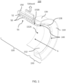
- the air delivery manifold 110 comprises a patient tunnel portion 120, a front funnel portion 130, and a plurality of gamma detectors 50 housed inside the PET scanner gantry 100 and positioned behind the front funnel portion 130.
- the front funnel portion 130 comprises an annular interior wall 132 defining an entry opening of the patient tunnel portion 120; and an air plenum 134 comprising an annular cavity structure for carrying a flow of pressurized air received from one or more remote source (not shown).
- the annular cavity structure of the air plenum 134 has an interior space 134' that carries the flow of pressurized air.
- the annular cavity structure of the air plenum 134 in one embodiment can also be described as having a substantially toroid shape.
- the illustration in FIG. 1 is a cross-sectioned view of the PET scanner gantry 100 and shows about half of the annular cavity structure of the air plenum 134.
- cooling air delivery manifold 110 of the present disclosure allows the one or more sources of the pressurized cooling air, i.e., the hardware such as fans or impellers that provide the supply of pressurized cooling air, to be located remote from the PET scanner system so that the patient in the PET scanner can be insulated from the noise of such hardware.
- the hardware such as fans or impellers that provide the supply of pressurized cooling air
- the air plenum 134 comprises an annular nozzle 135 configured for directing the flow of pressurized cooling air from the interior space 134' toward the plurality of gamma detectors 50.
- the air nozzle 135 can be better seen in the more detailed views in FIGS. 2 and 3 .
- Each of the discrete detector in the array of gamma detectors 50 have one or more heatsinks 52 attached to it to cool the detector.
- the air plenum 134 further comprises an airfoil surface 136 located adjacent to and downstream of the annular nozzle 135.
- the annular nozzle 135 is divided into a series of non-continuous slots by a plurality of fins 138 provided at regular intervals along the annular structure of the air plenum 134.
- the plurality of fins 138 can be better seen in FIGS. 1 and 3 .
- the plurality of fins 138 are oriented parallel to the longitudinal axis of the patient tunnel portion 120 so that the pressurized cooling air exiting each of the non-continuous slots in the annular nozzle 135 is directed toward the gamma detectors 50 in detector electronic assembly (DEA) 55.
- DEA detector electronic assembly
- annular nozzle 135 into a series of non-continuous slots helps with maintaining balanced radially uniform flow of the cooling air around the circumference of the front funnel portion 130.
- DEA 55 is depicted in FIG. 1 .
- a plurality of such DEA 55 are arranged circumferentially around the exterior of a first annular surface 132A forming detector rings.
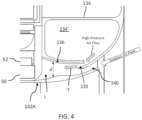
- the annular interior wall 132 is nested inside the annular structure of the air plenum 134, whereby a supplemental air inlet 140 is formed between the annular interior wall 132 and the air plenum 134, whereby when the pressurized air flows out of the annular nozzle 135, ambient air is drawn through the supplemental air inlet 140 and merges with the pressurized air exiting the annular nozzle 135 and flows toward the plurality of gamma detectors 50.
- a supplemental air inlet 140 is formed between the annular interior wall 132 and the air plenum 134, whereby when the pressurized air flows out of the annular nozzle 135, ambient air is drawn through the supplemental air inlet 140 and merges with the pressurized air exiting the annular nozzle 135 and flows toward the plurality of gamma detectors 50.
- the plurality of fins 138 also connect the air plenum 134 to the annular interior wall 132.
- the plurality of fins 138 maintain a desired spacing between the air plenum 134 and the annular interior wall 132 which forms the supplemental air inlet 140.
- the provision of the plurality of fins 138 is applicable to all of the embodiments of the PET scanner gantry 100 and PET scanner system disclosed herein.
- the plurality of fins 138 also provides the function of supporting the air plenum 134 under high pressure of the pressurized cooling air filling the interior space 134' by providing structural rigidity to the air plenum. Because the air plenum 134 is essentially a curved tube that has a disconnected side wall formed by the annular nozzle 135, without the support structure such as the fins 138 holding the edges of the annular nozzle 135 in place and preventing them from bursting outward from the pressure of the pressurized cooling air, the air plenum 134 may not hold its shape.
- the annular interior wall 132 comprises a first annular surface 132A facing the tunnel space S defined by the patient tunnel portion 120 and a second annular surface 132B facing the air plenum.
- the airfoil surface 136 is contoured such that the surface falls away from the trajectory T of the high-velocity pressure driven air exiting the annular nozzle 135.
- the distance d between the airfoil surface 136 and the second annular surface 132B of the annular interior wall 132 increases away from the annular nozzle 135.
- the volume of space between the airfoil surface 136 and the annular interior wall 132 increases in the direction toward the gamma detectors 50.
- the contour of the airfoil surface 136 causes the high-velocity air exiting the annular nozzle 135 to hug the airfoil surface 136 and skim the airfoil surface 136 as it flows away from the annular nozzle 135 and toward the gamma detectors 50.
- the air expands in volume, producing a low pressure area L between the airfoil surface 136 and the second annular surface 132B because of the inertance principle.
- This low pressure area L creates a suction that draws in the ambient air through the supplemental air inlet 140.
- the additional air drawn in from the ambient through the supplemental air inlet 140 joins the flow of the high-velocity cooling air, thus, amplifying the total amount of cooling air directed to the gamma detectors 50. Because this process of adding additional air is accomplished without any additional moving hardware such as fans or impellers, there is no additional noise generated while increasing the volume of cooling air flow.
- the airfoil surface 136 feature provided on the air plenum 134 is applicable to all of the embodiments of the PET scanner gantry 100 and PET scanner system disclosed herein.
- the cooling air can be provided from a remote source to the air plenum 134.
- the remote source for the cooling air can be located at some distance away from the PET scanner to minimize the noise to a patient that would be positioned in the scanner tunnel.
- the remote source can be located in a different room from the PET scanner to minimize the noise at the PET scanner for the patient's comfort.
- the remote source of cooling air can be pressurized plant air, sometimes referred to as facilities air, in which case the air plenum 134 just need to be connected to the plant air ducting.
- the remote source can be one or more fans or impellers that are appropriately configured to provide a desired amount of the cooling air to the air plenum 134.
- the remote source for the cooling air can be one or more fans or impellers located on or around the gantry structure.
- appropriate sound proofing packaging can be provided for the remote source for the cooling air to muffle and minimize the noise produced by the remote source.
- the air plenum 134 can comprise one or more air inlets 160 for receiving the flow of pressurized air from the remote source.
- FIG. 5 shows an embodiment of the PET scanner gantry 100 of the present disclosure that has two such air inlets 160 as an example.
- a plurality of sources for the pressurized cooling air supply can be connected to the air inlet 160 of the air plenum 134.
- some examples of the sources for the pressurized cooling air supply can be fan(s) or impeller(s). Having multiple sources for the pressurized air provides redundancy which can provide improved reliability of the system. Additionally, when there are multiple sources for the pressurized air, the fans in the individual air source can run at lower speed, thus reducing the amount of noise generated.
- housing 150 can direct the now heated exhaust air to the ambient surrounding. This is shown in FIGS. 1 and 2 .
- the air plenum 134 can be configured to incorporate a guided exhaust duct 134'-II that can direct the heated exhaust air away from the PET scanner via an exhaust outlet 180.
- An example of such exhaust outlet 180 is shown in FIG. 5 .
- the interior space 134' of the air plenum 134 is divided into two main sections, the cooling air duct portiom 134'-I that is configured to deliver the pressurized air for cooling, and the exhaust air duct portion 134'-II that is configured to direct the flow of heated exhaust air away from the PET scanner via the exhaust outlet 180.
- the exhaust air duct portion 134'-II receives a flow of exhaust air and directs the exhaust air away from the medical image scanner, wherien
- the flow of heated exhaust air is the cooling air flow after the cooling air flow has flown over the plurality of gamma detectors and returned to the air plenum 134 by the DEA housing 155.
- air delivery manifold can comprise an assembly of more than one unconnected air plenums.
- the cooling air delivery manifold 110 can be comprised of two air plenums 134A and 134B.
- the cooling air delivery manifold 110 can be comprised of three air plenums 134C, 134D, and 134E.
- the cooling air delivery manifold 110 can be comprised of four air plenums 134F, 134G, 134H, and 1341.
- each of the air plenums 134A - 134I can comprise at least one air inlet 160A - 160I, respectively.
- These multiple unconnected air plenums can each be configured to have both cooling air duct and exhaust air duct within each of the air plenum similar to the embodiment shown in FIGS. 6-7 .
- Each of the air plenums 134A-134I would comprise an air inlet and an air outlet.
- each air plenum has a volume of interior space and each air plenum comprises one or more air inlet Air-in that is connected to a source for the pressurized cooling air.
- each of the more than one air plenums can be connected to its own supply source for the pressurized cooling air or they can share one supply source for the pressurized cooling air.
- a PET scanner system that is fitted with the PET scanner gantry 100 incorporating a cooling air delivery manifold 110 according to the present disclosure is disclosed.
- the cooling air delivery manifold 110 Compared to the conventional PET scanner detector cooling systems, in which the array of gamma detectors with the associated detector electronic assemblies on the detector rings are often provided with an array of cooling fans, the cooling air delivery manifold 110 provides a system that is less noisy and more reliable.
Landscapes
- Health & Medical Sciences (AREA)
- Life Sciences & Earth Sciences (AREA)
- Engineering & Computer Science (AREA)
- Medical Informatics (AREA)
- Physics & Mathematics (AREA)
- Molecular Biology (AREA)
- High Energy & Nuclear Physics (AREA)
- Radiology & Medical Imaging (AREA)
- Surgery (AREA)
- Pathology (AREA)
- Nuclear Medicine, Radiotherapy & Molecular Imaging (AREA)
- Biomedical Technology (AREA)
- Heart & Thoracic Surgery (AREA)
- Biophysics (AREA)
- Optics & Photonics (AREA)
- Animal Behavior & Ethology (AREA)
- General Health & Medical Sciences (AREA)
- Public Health (AREA)
- Veterinary Medicine (AREA)
- General Physics & Mathematics (AREA)
- Spectroscopy & Molecular Physics (AREA)
- Nuclear Medicine (AREA)
- Apparatus For Radiation Diagnosis (AREA)
Claims (21)
- Portique de scanner d'imagerie médicale (100) comprenant :
un distributeur d'air de refroidissement (110) comprenant :une partie tunnel pour patient (120) ; etune partie entonnoir avant (130) ;une pluralité de détecteurs gamma (50) logés à l'intérieur du portique de scanner d'imagerie médicale (100) et positionnés derrière la partie entonnoir avant (130) qui comprend :une paroi intérieure annulaire (132) définissant une ouverture d'entrée de la partie tunnel pour patient (120) ; etune chambre à air (134) comprenant une structure annulaire destinée à transporter un écoulement d'air comprimé reçu depuis une source distante, la chambre à air (134) comprenant une buse annulaire (135) configurée pour diriger l'écoulement d'air comprimé vers la pluralité de détecteurs gamma (50) sous la forme d'un écoulement d'air à grande vitesse pour refroidir la pluralité de détecteurs gamma (50) et leurs composants électroniques associés ;dans lequel la paroi intérieure annulaire (132) est imbriquée à l'intérieur de la structure annulaire de la chambre à air (134), moyennant quoi une entrée d'air supplémentaire (140) est formée entre la paroi intérieure annulaire (132) et la chambre à air (134), moyennant quoi, quand l'écoulement d'air à grande vitesse s'écoule hors de la buse annulaire (135), l'air ambiant est aspiré par l'entrée d'air supplémentaire (140) et se mélange avec l'écoulement d'air à grande vitesse sortant de la buse annulaire (135) et s'écoule vers la pluralité de détecteurs gamma (50) en tant qu'écoulement d'air de refroidissement. - Portique de scanner d'imagerie médicale (100) selon la revendication 1, dans lequel la chambre à air (134) comprend en outre une surface aérodynamique (136) située au voisinage et en aval de la buse annulaire (135) pour diriger l'écoulement d'air à grande vitesse vers les détecteurs (50).
- Portique de scanner d'imagerie médicale (100) selon la revendication 1 ou 2, comprenant en outre une pluralité d'ailettes (138) reliant la chambre à air (134) à la paroi intérieure annulaire (132).
- Portique de scanner d'imagerie médicale (100) selon la revendication 3, dans lequel la pluralité d'ailettes (138) maintiennent un espacement souhaité entre la chambre à air (134) et la paroi intérieure annulaire (132) qui forme l'entrée d'air supplémentaire (140).
- Portique de scanner d'imagerie médicale (100) selon la revendication 1 ou 2, dans lequel la chambre à air (134) comprend une entrée d'air (160) destinée à recevoir l'écoulement d'air comprimé provenant d'une source distante.
- Portique de scanner d'imagerie médicale (100) selon la revendication 1, dans lequel la paroi intérieure annulaire (132) comprend une première surface annulaire (132A) faisant face à l'ouverture d'entrée de la partie tunnel pour patient (120) et une deuxième surface annulaire (132B) faisant face à la chambre à air (134) et comprenant en outre une arête annulaire disposée sur la deuxième surface annulaire (132B) et située en aval de la buse annulaire (135).
- Portique de scanner d'imagerie médicale (100) selon la revendication 1, dans lequel la chambre à air (134) comprend :une partie conduit d'air de refroidissement (134'-1) destinée à transporter l'écoulement d'air comprimé, la partie conduit d'air de refroidissement (134'-1) comportant la buse annulaire (135) ; etune partie conduit d'air d'échappement (134'-II) destinée à recevoir un écoulement d'air d'échappement et diriger l'air d'échappement loin du portique de scanner d'imagerie médicale (100), l'écoulement d'air d'échappement étant ledit écoulement d'air de refroidissement après que ledit écoulement d'air de refroidissement s'est écoulé par-dessus la pluralité de détecteurs gamma (50).
- Portique de scanner d'imagerie médicale (100) comprenant :
un distributeur d'air de refroidissement (110) comprenant :une partie tunnel pour patient (120) ; etune partie entonnoir avant (130) ;une pluralité de détecteurs gamma (50) logés à l'intérieur du portique de scanner d'imagerie médicale (100) et positionnés derrière la partie entonnoir avant (130) qui comprend :une paroi intérieure annulaire (132) définissant une ouverture d'entrée de la partie tunnel pour patient (120) ; etun ensemble d'au moins deux chambres à air (134A, 134B), chacune des au moins deux chambres à air (134A, 134B) ayant une structure incurvée, lesquelles forment conjointement un ensemble annulaire, chacune des au moins deux chambres à air (134A, 134B) comprenant une structure destinée à transporter un écoulement d'air comprimé reçu depuis une source distante, chacune des au moins deux chambres à air (134A, 134B) comprenant en outre une buse incurvée configurée pour diriger l'écoulement d'air comprimé vers la pluralité de détecteurs gamma (50) sous la forme d'un écoulement d'air à grande vitesse pour refroidir la pluralité de détecteurs gamma (50) et leurs composants électroniques associés ;dans lequel la paroi intérieure annulaire (132) est imbriquée à l'intérieur de l'ensemble annulaire formé par les au moins deux chambres à air (134A, 134B), moyennant quoi une entrée d'air supplémentaire (140) est formée entre la paroi intérieure annulaire (132) et les au moins deux chambres à air (134A, 134B), moyennant quoi, quand l'écoulement d'air à grande vitesse s'écoule hors des buses incurvées, l'air ambiant est aspiré par l'entrée d'air supplémentaire (140) et se mélange avec l'écoulement d'air à grande vitesse sortant des buses incurvées et s'écoule vers la pluralité de détecteurs gamma (50) en tant qu'écoulement d'air de refroidissement. - Portique de scanner d'imagerie médicale (100) selon la revendication 8, dans lequel chacune des au moins deux chambres à air (134A, 134B) comprend en outre une surface aérodynamique (136) située au voisinage et en aval de la buse incurvée pour diriger l'écoulement d'air à grande vitesse vers les détecteurs (50).
- Portique de scanner d'imagerie médicale (100) selon la revendication 8, comprenant en outre une pluralité d'ailettes (138) reliant les au moins deux chambres à air (134A, 134B) à la paroi intérieure annulaire (132).
- Portique de scanner d'imagerie médicale (100) selon la revendication 8, dans lequel chacune des au moins deux chambres à air (134A, 134B) comprend :une partie conduit d'air de refroidissement (134'-1) destinée à transporter l'écoulement d'air comprimé, la partie conduit d'air de refroidissement (134'-1) comportant la buse incurvée ; etune partie conduit d'air d'échappement (134'-II) destinée à recevoir un écoulement d'air d'échappement et diriger l'air d'échappement loin du scanner d'imagerie médicale, l'écoulement d'air d'échappement étant ledit écoulement d'air de refroidissement après que ledit écoulement d'air de refroidissement s'est écoulé par-dessus la pluralité de détecteurs gamma (50).
- Système de scanner d'imagerie médicale, comprenant :le portique de scanner d'imagerie médicale (100) selon l'une quelconque des revendications 1 à 7 ; etune source distante destinée à fournir l'écoulement d'air comprimé reçu par la chambre à air (134).
- Portique de scanner d'imagerie médicale (100) selon la revendication 1, dans lequel l'air ambiant aspiré par l'entrée d'air supplémentaire (140) et se mélangeant avec l'écoulement d'air à grande vitesse sortant de la buse annulaire (135) ne génère pas de bruit supplémentaire.
- Portique de scanner d'imagerie médicale (100) selon la revendication 13, dans lequel l'air ambiant aspiré par l'entrée d'air supplémentaire (140) et se mélangeant avec l'écoulement d'air à grande vitesse sortant de la buse annulaire (135) ne génère pas de bruit supplémentaire en raison d'une absence de besoin de ventilateurs ou turbines supplémentaires.
- Système de scanner d'imagerie médicale selon la revendication 12, dans lequel le fait de prévoir une source distante pour l'air comprimé minimise le bruit au niveau du portique de scanner d'imagerie médicale (100).
- Système de scanner d'imagerie médicale selon la revendication 12, dans lequel la source distante est distante du portique de scanner d'imagerie médicale (100).
- Système de scanner d'imagerie médicale selon la revendication 12, dans lequel la source distante comprend au moins un élément parmi de l'air comprimé d'usine, un ou plusieurs ventilateurs ou une ou plusieurs turbines.
- Système de scanner d'imagerie médicale selon la revendication 17, dans lequel la source distante comprenant au moins deux sources permet au(x) ventilateur(s) de fonctionner à une vitesse réduite.
- Système de scanner d'imagerie médicale selon la revendication 18, dans lequel le bruit est encore réduit en raison de la vitesse réduite du ou des ventilateurs.
- Système de scanner d'imagerie médicale selon la revendication 12, dans lequel la source distante consiste en un ou plusieurs ventilateurs et turbines situés sur ou autour du portique (100).
- Système de scanner d'imagerie médicale selon la revendication 20, dans lequel la source distante est pourvue d'une insonorisation pour minimiser le bruit.
Applications Claiming Priority (1)
| Application Number | Priority Date | Filing Date | Title |
|---|---|---|---|
| PCT/US2020/070061 WO2021236172A1 (fr) | 2020-05-19 | 2020-05-19 | Portique de scanner de tep refroidi par air |
Publications (3)
| Publication Number | Publication Date |
|---|---|
| EP4135580A1 EP4135580A1 (fr) | 2023-02-22 |
| EP4135580B1 true EP4135580B1 (fr) | 2024-05-08 |
| EP4135580C0 EP4135580C0 (fr) | 2024-05-08 |
Family
ID=71070076
Family Applications (1)
| Application Number | Title | Priority Date | Filing Date |
|---|---|---|---|
| EP20731773.6A Active EP4135580B1 (fr) | 2020-05-19 | 2020-05-19 | Portique de scanner de tep refroidi par air |
Country Status (5)
| Country | Link |
|---|---|
| US (1) | US11998377B2 (fr) |
| EP (1) | EP4135580B1 (fr) |
| JP (1) | JP7483944B2 (fr) |
| CN (1) | CN115551412B (fr) |
| WO (1) | WO2021236172A1 (fr) |
Families Citing this family (4)
| Publication number | Priority date | Publication date | Assignee | Title |
|---|---|---|---|---|
| DE102020214467B4 (de) * | 2020-11-18 | 2023-01-19 | Siemens Healthcare Gmbh | Magnetresonanzvorrichtung mit einer Patientenbelüftungseinheit und ein Verfahren zu einem Steuern einer Patientenbelüftungseinheit |
| US12295767B2 (en) * | 2021-08-11 | 2025-05-13 | Shanghai United Imaging Healthcare Co., Ltd. | Detection apparatus and imaging apparatus |
| KR102855071B1 (ko) * | 2024-09-27 | 2025-09-09 | (주)에프티글로벌 | 양전자 방출 단층 촬영 장치용 갠트리 결합 구조 |
| KR102855066B1 (ko) * | 2024-09-27 | 2025-09-09 | (주)에프티글로벌 | 냉각시스템이 구비된 양전자 방출 단층 촬영 장치 |
Family Cites Families (25)
| Publication number | Priority date | Publication date | Assignee | Title |
|---|---|---|---|---|
| US5956383A (en) * | 1996-11-07 | 1999-09-21 | General Electric Company | Apparatus for removing heat from X-ray tube cooling fluid |
| JP3856511B2 (ja) | 1996-11-29 | 2006-12-13 | 株式会社日立メディコ | ポジトロンct装置用ガントリ |
| JP2001321373A (ja) * | 2000-05-18 | 2001-11-20 | Katsuhiro Ono | カソードスキャン型x線発生器を用いたx線ctスキャナ |
| JP2003290211A (ja) * | 2002-03-29 | 2003-10-14 | Ge Medical Systems Global Technology Co Llc | X線診断システム及び装置 |
| DE10304661B4 (de) * | 2003-02-05 | 2007-03-01 | Siemens Ag | Kühlsystem und Verfahren zur Kühlung einer Gantry |
| DE10312253B4 (de) | 2003-03-19 | 2007-04-05 | Siemens Ag | Kühlsystem, Computertomographie-Anlage mit einem solchen Kühlsystem und Verfahren zur Kühlung einer Gantry |
| US7065173B2 (en) | 2003-12-02 | 2006-06-20 | General Electric Company | Method and apparatus for thermal management of CT electronics |
| DE102005041538B4 (de) | 2005-08-31 | 2009-04-30 | Siemens Ag | Gantry eines Computertomographen |
| DE102006024972B4 (de) | 2006-05-29 | 2008-08-21 | Siemens Ag | Vorrichtung zur Kühlung eines Röntgenstrahlungsdetektors und Kühlsystem für eine Strahlungsdetektoranordnung |
| DE102007037313B4 (de) * | 2007-08-08 | 2009-11-12 | Siemens Ag | Computertomographiegerät mit einer Gantry zur Halterung von um eine Systemachse rotierbar angeordneten Komponenten eines Aufnahmesystems |
| US8282278B2 (en) | 2007-11-30 | 2012-10-09 | Koninklijke Philips Electronics N.V. | Gantry cooling |
| JP2013084572A (ja) * | 2011-09-27 | 2013-05-09 | Toshiba Corp | 冷却機 |
| US8481949B2 (en) | 2011-11-14 | 2013-07-09 | Siemens Medical Solutions Usa, Inc. | Apparatus and methods for cooling positron emission tomography scanner detector crystals |
| CN103860187B (zh) | 2012-12-10 | 2015-05-13 | 上海联影医疗科技有限公司 | 一种正电子发射断层扫描仪的冷却系统 |
| KR101722689B1 (ko) * | 2015-02-12 | 2017-04-03 | 삼성전자주식회사 | 냉각 ct 시스템 |
| CN204392758U (zh) * | 2015-02-13 | 2015-06-10 | 上海联影医疗科技有限公司 | 一种医疗影像设备的风冷散热系统 |
| US10001569B2 (en) * | 2015-08-31 | 2018-06-19 | General Electric Company | Positron emission tomography detector assembly for dual-modality imaging |
| CN105704982B (zh) * | 2015-12-18 | 2017-12-22 | 上海联影医疗科技有限公司 | 一种用于医学成像装置的冷却系统 |
| CN205514644U (zh) * | 2016-03-15 | 2016-08-31 | 上海联影医疗科技有限公司 | 一种乳腺成像装置 |
| US10054698B2 (en) * | 2016-08-31 | 2018-08-21 | General Electric Company | Temperature stabilization for detector heads |
| US10267930B2 (en) * | 2016-09-30 | 2019-04-23 | Shanghai United Imaging Healthcare Co., Ltd. | Systems for PET imaging |
| GB2567193A (en) * | 2017-10-05 | 2019-04-10 | Elekta ltd | Image guided radiation therapy apparatus |
| GB2569797B (en) * | 2017-12-21 | 2020-03-25 | Elekta ltd | Light circuit for imaging device |
| US10353084B1 (en) * | 2018-04-02 | 2019-07-16 | General Electric Company | Systems and methods for cooling an imaging system |
| WO2020057654A1 (fr) * | 2018-09-21 | 2020-03-26 | Shanghai United Imaging Healthcare Co., Ltd. | Systèmes pour l'imagerie |
-
2020
- 2020-05-19 EP EP20731773.6A patent/EP4135580B1/fr active Active
- 2020-05-19 US US17/757,152 patent/US11998377B2/en active Active
- 2020-05-19 JP JP2022569255A patent/JP7483944B2/ja active Active
- 2020-05-19 CN CN202080101067.8A patent/CN115551412B/zh active Active
- 2020-05-19 WO PCT/US2020/070061 patent/WO2021236172A1/fr not_active Ceased
Also Published As
| Publication number | Publication date |
|---|---|
| EP4135580C0 (fr) | 2024-05-08 |
| JP7483944B2 (ja) | 2024-05-15 |
| EP4135580A1 (fr) | 2023-02-22 |
| WO2021236172A1 (fr) | 2021-11-25 |
| US20220409155A1 (en) | 2022-12-29 |
| JP2023526306A (ja) | 2023-06-21 |
| CN115551412A (zh) | 2022-12-30 |
| CN115551412B (zh) | 2025-09-09 |
| US11998377B2 (en) | 2024-06-04 |
Similar Documents
| Publication | Publication Date | Title |
|---|---|---|
| EP4135580B1 (fr) | Portique de scanner de tep refroidi par air | |
| CN1891017B (zh) | X射线管组件、冷却系统及二者组合和该组件的冷却方法 | |
| CN101574265B (zh) | X射线计算断层摄影装置 | |
| US20070222223A1 (en) | Wind turbine generators having wind assisted cooling systems and cooling methods | |
| US5956383A (en) | Apparatus for removing heat from X-ray tube cooling fluid | |
| JP2004237103A (ja) | コンピュータ断層撮影装置のガントリの冷却システムおよび冷却方法 | |
| CN102400929A (zh) | 风扇 | |
| US7374338B2 (en) | Gantry for a computed tomography apparatus and method for cooling a gantry | |
| JP2020504885A5 (fr) | ||
| CN111743559B (zh) | 用于计算机断层摄影设备的冷却系统和冷却方法 | |
| JP2004283577A (ja) | ガントリの冷却システムおよび冷却方法 | |
| US20040240619A1 (en) | Optimized x-ray tube cooling device | |
| US7072445B2 (en) | Controlling cooling air in CT system | |
| CN108392218B (zh) | 一种pet设备的风冷装置 | |
| CN110448325A (zh) | 一种pet系统风冷散热装置 | |
| US8197136B2 (en) | Tomography apparatus with an annular airflow channel with an air-diverting ventilation element | |
| CN217219038U (zh) | Ct机风冷散热通道、ct机风冷散热系统及ct机 | |
| CN114246606A (zh) | 改善核成像系统中的患者舒适度 | |
| EP4001593A1 (fr) | Une aube directrice de turbine à gaz comprenant une plate-forme interne refroidie par impact | |
| CN213478401U (zh) | 涡轮叶片冷却系统及航空发动机 | |
| CN107912001B (zh) | 医疗影像设备检测器的散热装置 | |
| CN117939863A (zh) | 用于医疗影像设备的低噪音控温装置和方法及医疗影像设备 | |
| US11421695B2 (en) | Turbomachines with decoupled collectors | |
| CN219397308U (zh) | 医疗设备 | |
| WO2025014508A1 (fr) | Atténuation de bruit pour système d'imagerie nucléaire |
Legal Events
| Date | Code | Title | Description |
|---|---|---|---|
| STAA | Information on the status of an ep patent application or granted ep patent |
Free format text: STATUS: UNKNOWN |
|
| STAA | Information on the status of an ep patent application or granted ep patent |
Free format text: STATUS: THE INTERNATIONAL PUBLICATION HAS BEEN MADE |
|
| PUAI | Public reference made under article 153(3) epc to a published international application that has entered the european phase |
Free format text: ORIGINAL CODE: 0009012 |
|
| STAA | Information on the status of an ep patent application or granted ep patent |
Free format text: STATUS: REQUEST FOR EXAMINATION WAS MADE |
|
| 17P | Request for examination filed |
Effective date: 20221116 |
|
| AK | Designated contracting states |
Kind code of ref document: A1 Designated state(s): AL AT BE BG CH CY CZ DE DK EE ES FI FR GB GR HR HU IE IS IT LI LT LU LV MC MK MT NL NO PL PT RO RS SE SI SK SM TR |
|
| DAV | Request for validation of the european patent (deleted) | ||
| DAX | Request for extension of the european patent (deleted) | ||
| GRAP | Despatch of communication of intention to grant a patent |
Free format text: ORIGINAL CODE: EPIDOSNIGR1 |
|
| STAA | Information on the status of an ep patent application or granted ep patent |
Free format text: STATUS: GRANT OF PATENT IS INTENDED |
|
| INTG | Intention to grant announced |
Effective date: 20231205 |
|
| GRAS | Grant fee paid |
Free format text: ORIGINAL CODE: EPIDOSNIGR3 |
|
| GRAA | (expected) grant |
Free format text: ORIGINAL CODE: 0009210 |
|
| STAA | Information on the status of an ep patent application or granted ep patent |
Free format text: STATUS: THE PATENT HAS BEEN GRANTED |
|
| AK | Designated contracting states |
Kind code of ref document: B1 Designated state(s): AL AT BE BG CH CY CZ DE DK EE ES FI FR GB GR HR HU IE IS IT LI LT LU LV MC MK MT NL NO PL PT RO RS SE SI SK SM TR |
|
| REG | Reference to a national code |
Ref country code: GB Ref legal event code: FG4D |
|
| REG | Reference to a national code |
Ref country code: CH Ref legal event code: EP |
|
| REG | Reference to a national code |
Ref country code: DE Ref legal event code: R096 Ref document number: 602020030623 Country of ref document: DE |
|
| REG | Reference to a national code |
Ref country code: IE Ref legal event code: FG4D |
|
| U01 | Request for unitary effect filed |
Effective date: 20240508 |
|
| U07 | Unitary effect registered |
Designated state(s): AT BE BG DE DK EE FI FR IT LT LU LV MT NL PT SE SI Effective date: 20240523 |
|
| U20 | Renewal fee for the european patent with unitary effect paid |
Year of fee payment: 5 Effective date: 20240523 |
|
| PG25 | Lapsed in a contracting state [announced via postgrant information from national office to epo] |
Ref country code: IS Free format text: LAPSE BECAUSE OF FAILURE TO SUBMIT A TRANSLATION OF THE DESCRIPTION OR TO PAY THE FEE WITHIN THE PRESCRIBED TIME-LIMIT Effective date: 20240908 |
|
| PG25 | Lapsed in a contracting state [announced via postgrant information from national office to epo] |
Ref country code: HR Free format text: LAPSE BECAUSE OF FAILURE TO SUBMIT A TRANSLATION OF THE DESCRIPTION OR TO PAY THE FEE WITHIN THE PRESCRIBED TIME-LIMIT Effective date: 20240508 |
|
| PG25 | Lapsed in a contracting state [announced via postgrant information from national office to epo] |
Ref country code: GR Free format text: LAPSE BECAUSE OF FAILURE TO SUBMIT A TRANSLATION OF THE DESCRIPTION OR TO PAY THE FEE WITHIN THE PRESCRIBED TIME-LIMIT Effective date: 20240809 |
|
| PG25 | Lapsed in a contracting state [announced via postgrant information from national office to epo] |
Ref country code: ES Free format text: LAPSE BECAUSE OF FAILURE TO SUBMIT A TRANSLATION OF THE DESCRIPTION OR TO PAY THE FEE WITHIN THE PRESCRIBED TIME-LIMIT Effective date: 20240508 |
|
| PG25 | Lapsed in a contracting state [announced via postgrant information from national office to epo] |
Ref country code: PL Free format text: LAPSE BECAUSE OF FAILURE TO SUBMIT A TRANSLATION OF THE DESCRIPTION OR TO PAY THE FEE WITHIN THE PRESCRIBED TIME-LIMIT Effective date: 20240508 |
|
| PG25 | Lapsed in a contracting state [announced via postgrant information from national office to epo] |
Ref country code: PL Free format text: LAPSE BECAUSE OF FAILURE TO SUBMIT A TRANSLATION OF THE DESCRIPTION OR TO PAY THE FEE WITHIN THE PRESCRIBED TIME-LIMIT Effective date: 20240508 Ref country code: NO Free format text: LAPSE BECAUSE OF FAILURE TO SUBMIT A TRANSLATION OF THE DESCRIPTION OR TO PAY THE FEE WITHIN THE PRESCRIBED TIME-LIMIT Effective date: 20240808 Ref country code: IS Free format text: LAPSE BECAUSE OF FAILURE TO SUBMIT A TRANSLATION OF THE DESCRIPTION OR TO PAY THE FEE WITHIN THE PRESCRIBED TIME-LIMIT Effective date: 20240908 Ref country code: HR Free format text: LAPSE BECAUSE OF FAILURE TO SUBMIT A TRANSLATION OF THE DESCRIPTION OR TO PAY THE FEE WITHIN THE PRESCRIBED TIME-LIMIT Effective date: 20240508 Ref country code: GR Free format text: LAPSE BECAUSE OF FAILURE TO SUBMIT A TRANSLATION OF THE DESCRIPTION OR TO PAY THE FEE WITHIN THE PRESCRIBED TIME-LIMIT Effective date: 20240809 Ref country code: ES Free format text: LAPSE BECAUSE OF FAILURE TO SUBMIT A TRANSLATION OF THE DESCRIPTION OR TO PAY THE FEE WITHIN THE PRESCRIBED TIME-LIMIT Effective date: 20240508 Ref country code: RS Free format text: LAPSE BECAUSE OF FAILURE TO SUBMIT A TRANSLATION OF THE DESCRIPTION OR TO PAY THE FEE WITHIN THE PRESCRIBED TIME-LIMIT Effective date: 20240808 |
|
| REG | Reference to a national code |
Ref country code: CH Ref legal event code: PL |
|
| PG25 | Lapsed in a contracting state [announced via postgrant information from national office to epo] |
Ref country code: CZ Free format text: LAPSE BECAUSE OF FAILURE TO SUBMIT A TRANSLATION OF THE DESCRIPTION OR TO PAY THE FEE WITHIN THE PRESCRIBED TIME-LIMIT Effective date: 20240508 |
|
| PG25 | Lapsed in a contracting state [announced via postgrant information from national office to epo] |
Ref country code: SK Free format text: LAPSE BECAUSE OF FAILURE TO SUBMIT A TRANSLATION OF THE DESCRIPTION OR TO PAY THE FEE WITHIN THE PRESCRIBED TIME-LIMIT Effective date: 20240508 Ref country code: RO Free format text: LAPSE BECAUSE OF FAILURE TO SUBMIT A TRANSLATION OF THE DESCRIPTION OR TO PAY THE FEE WITHIN THE PRESCRIBED TIME-LIMIT Effective date: 20240508 |
|
| PG25 | Lapsed in a contracting state [announced via postgrant information from national office to epo] |
Ref country code: SM Free format text: LAPSE BECAUSE OF FAILURE TO SUBMIT A TRANSLATION OF THE DESCRIPTION OR TO PAY THE FEE WITHIN THE PRESCRIBED TIME-LIMIT Effective date: 20240508 |
|
| PG25 | Lapsed in a contracting state [announced via postgrant information from national office to epo] |
Ref country code: SM Free format text: LAPSE BECAUSE OF FAILURE TO SUBMIT A TRANSLATION OF THE DESCRIPTION OR TO PAY THE FEE WITHIN THE PRESCRIBED TIME-LIMIT Effective date: 20240508 Ref country code: SK Free format text: LAPSE BECAUSE OF FAILURE TO SUBMIT A TRANSLATION OF THE DESCRIPTION OR TO PAY THE FEE WITHIN THE PRESCRIBED TIME-LIMIT Effective date: 20240508 Ref country code: RO Free format text: LAPSE BECAUSE OF FAILURE TO SUBMIT A TRANSLATION OF THE DESCRIPTION OR TO PAY THE FEE WITHIN THE PRESCRIBED TIME-LIMIT Effective date: 20240508 Ref country code: CZ Free format text: LAPSE BECAUSE OF FAILURE TO SUBMIT A TRANSLATION OF THE DESCRIPTION OR TO PAY THE FEE WITHIN THE PRESCRIBED TIME-LIMIT Effective date: 20240508 Ref country code: CH Free format text: LAPSE BECAUSE OF NON-PAYMENT OF DUE FEES Effective date: 20240531 |
|
| PG25 | Lapsed in a contracting state [announced via postgrant information from national office to epo] |
Ref country code: MC Free format text: LAPSE BECAUSE OF FAILURE TO SUBMIT A TRANSLATION OF THE DESCRIPTION OR TO PAY THE FEE WITHIN THE PRESCRIBED TIME-LIMIT Effective date: 20240508 |
|
| REG | Reference to a national code |
Ref country code: DE Ref legal event code: R097 Ref document number: 602020030623 Country of ref document: DE |
|
| PLBE | No opposition filed within time limit |
Free format text: ORIGINAL CODE: 0009261 |
|
| STAA | Information on the status of an ep patent application or granted ep patent |
Free format text: STATUS: NO OPPOSITION FILED WITHIN TIME LIMIT |
|
| 26N | No opposition filed |
Effective date: 20250211 |
|
| PG25 | Lapsed in a contracting state [announced via postgrant information from national office to epo] |
Ref country code: IE Free format text: LAPSE BECAUSE OF NON-PAYMENT OF DUE FEES Effective date: 20240519 |
|
| U20 | Renewal fee for the european patent with unitary effect paid |
Year of fee payment: 6 Effective date: 20250520 |
|
| PGFP | Annual fee paid to national office [announced via postgrant information from national office to epo] |
Ref country code: GB Payment date: 20250610 Year of fee payment: 6 |
|
| PG25 | Lapsed in a contracting state [announced via postgrant information from national office to epo] |
Ref country code: CY Free format text: LAPSE BECAUSE OF FAILURE TO SUBMIT A TRANSLATION OF THE DESCRIPTION OR TO PAY THE FEE WITHIN THE PRESCRIBED TIME-LIMIT; INVALID AB INITIO Effective date: 20200519 |
|
| PG25 | Lapsed in a contracting state [announced via postgrant information from national office to epo] |
Ref country code: HU Free format text: LAPSE BECAUSE OF FAILURE TO SUBMIT A TRANSLATION OF THE DESCRIPTION OR TO PAY THE FEE WITHIN THE PRESCRIBED TIME-LIMIT; INVALID AB INITIO Effective date: 20200519 |