EP4135789B1 - Dialysatregenerator und system damit - Google Patents
Dialysatregenerator und system damit Download PDFInfo
- Publication number
- EP4135789B1 EP4135789B1 EP21721241.4A EP21721241A EP4135789B1 EP 4135789 B1 EP4135789 B1 EP 4135789B1 EP 21721241 A EP21721241 A EP 21721241A EP 4135789 B1 EP4135789 B1 EP 4135789B1
- Authority
- EP
- European Patent Office
- Prior art keywords
- dialysate
- regenerator
- pump
- compartment
- chamber
- Prior art date
- Legal status (The legal status is an assumption and is not a legal conclusion. Google has not performed a legal analysis and makes no representation as to the accuracy of the status listed.)
- Active
Links
Images








Classifications
-
- A—HUMAN NECESSITIES
- A61—MEDICAL OR VETERINARY SCIENCE; HYGIENE
- A61M—DEVICES FOR INTRODUCING MEDIA INTO, OR ONTO, THE BODY; DEVICES FOR TRANSDUCING BODY MEDIA OR FOR TAKING MEDIA FROM THE BODY; DEVICES FOR PRODUCING OR ENDING SLEEP OR STUPOR
- A61M1/00—Suction or pumping devices for medical purposes; Devices for carrying-off, for treatment of, or for carrying-over, body-liquids; Drainage systems
- A61M1/14—Dialysis systems; Artificial kidneys; Blood oxygenators ; Reciprocating systems for treatment of body fluids, e.g. single needle systems for hemofiltration or pheresis
- A61M1/16—Dialysis systems; Artificial kidneys; Blood oxygenators ; Reciprocating systems for treatment of body fluids, e.g. single needle systems for hemofiltration or pheresis with membranes
- A61M1/1694—Dialysis systems; Artificial kidneys; Blood oxygenators ; Reciprocating systems for treatment of body fluids, e.g. single needle systems for hemofiltration or pheresis with membranes with recirculating dialysing liquid
- A61M1/1696—Dialysis systems; Artificial kidneys; Blood oxygenators ; Reciprocating systems for treatment of body fluids, e.g. single needle systems for hemofiltration or pheresis with membranes with recirculating dialysing liquid with dialysate regeneration
-
- A—HUMAN NECESSITIES
- A61—MEDICAL OR VETERINARY SCIENCE; HYGIENE
- A61M—DEVICES FOR INTRODUCING MEDIA INTO, OR ONTO, THE BODY; DEVICES FOR TRANSDUCING BODY MEDIA OR FOR TAKING MEDIA FROM THE BODY; DEVICES FOR PRODUCING OR ENDING SLEEP OR STUPOR
- A61M1/00—Suction or pumping devices for medical purposes; Devices for carrying-off, for treatment of, or for carrying-over, body-liquids; Drainage systems
- A61M1/14—Dialysis systems; Artificial kidneys; Blood oxygenators ; Reciprocating systems for treatment of body fluids, e.g. single needle systems for hemofiltration or pheresis
- A61M1/15—Dialysis systems; Artificial kidneys; Blood oxygenators ; Reciprocating systems for treatment of body fluids, e.g. single needle systems for hemofiltration or pheresis with a cassette forming partially or totally the flow circuit for the treating fluid, e.g. the dialysate fluid circuit or the treating gas circuit
- A61M1/156—Constructional details of the cassette, e.g. specific details on material or shape
- A61M1/1563—Details of incorporated filters
-
- A—HUMAN NECESSITIES
- A61—MEDICAL OR VETERINARY SCIENCE; HYGIENE
- A61M—DEVICES FOR INTRODUCING MEDIA INTO, OR ONTO, THE BODY; DEVICES FOR TRANSDUCING BODY MEDIA OR FOR TAKING MEDIA FROM THE BODY; DEVICES FOR PRODUCING OR ENDING SLEEP OR STUPOR
- A61M1/00—Suction or pumping devices for medical purposes; Devices for carrying-off, for treatment of, or for carrying-over, body-liquids; Drainage systems
- A61M1/14—Dialysis systems; Artificial kidneys; Blood oxygenators ; Reciprocating systems for treatment of body fluids, e.g. single needle systems for hemofiltration or pheresis
- A61M1/16—Dialysis systems; Artificial kidneys; Blood oxygenators ; Reciprocating systems for treatment of body fluids, e.g. single needle systems for hemofiltration or pheresis with membranes
- A61M1/1601—Control or regulation
- A61M1/1603—Regulation parameters
-
- A—HUMAN NECESSITIES
- A61—MEDICAL OR VETERINARY SCIENCE; HYGIENE
- A61M—DEVICES FOR INTRODUCING MEDIA INTO, OR ONTO, THE BODY; DEVICES FOR TRANSDUCING BODY MEDIA OR FOR TAKING MEDIA FROM THE BODY; DEVICES FOR PRODUCING OR ENDING SLEEP OR STUPOR
- A61M1/00—Suction or pumping devices for medical purposes; Devices for carrying-off, for treatment of, or for carrying-over, body-liquids; Drainage systems
- A61M1/14—Dialysis systems; Artificial kidneys; Blood oxygenators ; Reciprocating systems for treatment of body fluids, e.g. single needle systems for hemofiltration or pheresis
- A61M1/16—Dialysis systems; Artificial kidneys; Blood oxygenators ; Reciprocating systems for treatment of body fluids, e.g. single needle systems for hemofiltration or pheresis with membranes
- A61M1/26—Dialysis systems; Artificial kidneys; Blood oxygenators ; Reciprocating systems for treatment of body fluids, e.g. single needle systems for hemofiltration or pheresis with membranes and internal elements which are moving
- A61M1/267—Dialysis systems; Artificial kidneys; Blood oxygenators ; Reciprocating systems for treatment of body fluids, e.g. single needle systems for hemofiltration or pheresis with membranes and internal elements which are moving used for pumping
-
- A—HUMAN NECESSITIES
- A61—MEDICAL OR VETERINARY SCIENCE; HYGIENE
- A61M—DEVICES FOR INTRODUCING MEDIA INTO, OR ONTO, THE BODY; DEVICES FOR TRANSDUCING BODY MEDIA OR FOR TAKING MEDIA FROM THE BODY; DEVICES FOR PRODUCING OR ENDING SLEEP OR STUPOR
- A61M1/00—Suction or pumping devices for medical purposes; Devices for carrying-off, for treatment of, or for carrying-over, body-liquids; Drainage systems
- A61M1/14—Dialysis systems; Artificial kidneys; Blood oxygenators ; Reciprocating systems for treatment of body fluids, e.g. single needle systems for hemofiltration or pheresis
- A61M1/28—Peritoneal dialysis ; Other peritoneal treatment, e.g. oxygenation
- A61M1/287—Dialysates therefor
-
- B—PERFORMING OPERATIONS; TRANSPORTING
- B01—PHYSICAL OR CHEMICAL PROCESSES OR APPARATUS IN GENERAL
- B01D—SEPARATION
- B01D15/00—Separating processes involving the treatment of liquids with solid sorbents; Apparatus therefor
- B01D15/08—Selective adsorption, e.g. chromatography
- B01D15/10—Selective adsorption, e.g. chromatography characterised by constructional or operational features
- B01D15/16—Selective adsorption, e.g. chromatography characterised by constructional or operational features relating to the conditioning of the fluid carrier
- B01D15/166—Fluid composition conditioning, e.g. gradient
-
- B—PERFORMING OPERATIONS; TRANSPORTING
- B01—PHYSICAL OR CHEMICAL PROCESSES OR APPARATUS IN GENERAL
- B01D—SEPARATION
- B01D15/00—Separating processes involving the treatment of liquids with solid sorbents; Apparatus therefor
- B01D15/08—Selective adsorption, e.g. chromatography
- B01D15/10—Selective adsorption, e.g. chromatography characterised by constructional or operational features
- B01D15/18—Selective adsorption, e.g. chromatography characterised by constructional or operational features relating to flow patterns
-
- B—PERFORMING OPERATIONS; TRANSPORTING
- B01—PHYSICAL OR CHEMICAL PROCESSES OR APPARATUS IN GENERAL
- B01D—SEPARATION
- B01D15/00—Separating processes involving the treatment of liquids with solid sorbents; Apparatus therefor
- B01D15/08—Selective adsorption, e.g. chromatography
- B01D15/26—Selective adsorption, e.g. chromatography characterised by the separation mechanism
- B01D15/36—Selective adsorption, e.g. chromatography characterised by the separation mechanism involving ionic interaction, e.g. ion-exchange, ion-pair, ion-suppression or ion-exclusion
- B01D15/361—Ion-exchange
- B01D15/362—Cation-exchange
-
- B—PERFORMING OPERATIONS; TRANSPORTING
- B01—PHYSICAL OR CHEMICAL PROCESSES OR APPARATUS IN GENERAL
- B01D—SEPARATION
- B01D15/00—Separating processes involving the treatment of liquids with solid sorbents; Apparatus therefor
- B01D15/08—Selective adsorption, e.g. chromatography
- B01D15/26—Selective adsorption, e.g. chromatography characterised by the separation mechanism
- B01D15/36—Selective adsorption, e.g. chromatography characterised by the separation mechanism involving ionic interaction, e.g. ion-exchange, ion-pair, ion-suppression or ion-exclusion
- B01D15/361—Ion-exchange
- B01D15/363—Anion-exchange
-
- B—PERFORMING OPERATIONS; TRANSPORTING
- B01—PHYSICAL OR CHEMICAL PROCESSES OR APPARATUS IN GENERAL
- B01J—CHEMICAL OR PHYSICAL PROCESSES, e.g. CATALYSIS OR COLLOID CHEMISTRY; THEIR RELEVANT APPARATUS
- B01J20/00—Solid sorbent compositions or filter aid compositions; Sorbents for chromatography; Processes for preparing, regenerating or reactivating thereof
- B01J20/02—Solid sorbent compositions or filter aid compositions; Sorbents for chromatography; Processes for preparing, regenerating or reactivating thereof comprising inorganic material
- B01J20/20—Solid sorbent compositions or filter aid compositions; Sorbents for chromatography; Processes for preparing, regenerating or reactivating thereof comprising inorganic material comprising free carbon; comprising carbon obtained by carbonising processes
-
- B—PERFORMING OPERATIONS; TRANSPORTING
- B01—PHYSICAL OR CHEMICAL PROCESSES OR APPARATUS IN GENERAL
- B01J—CHEMICAL OR PHYSICAL PROCESSES, e.g. CATALYSIS OR COLLOID CHEMISTRY; THEIR RELEVANT APPARATUS
- B01J20/00—Solid sorbent compositions or filter aid compositions; Sorbents for chromatography; Processes for preparing, regenerating or reactivating thereof
- B01J20/28—Solid sorbent compositions or filter aid compositions; Sorbents for chromatography; Processes for preparing, regenerating or reactivating thereof characterised by their form or physical properties
- B01J20/28014—Solid sorbent compositions or filter aid compositions; Sorbents for chromatography; Processes for preparing, regenerating or reactivating thereof characterised by their form or physical properties characterised by their form
- B01J20/2805—Sorbents inside a permeable or porous casing, e.g. inside a container, bag or membrane
-
- B—PERFORMING OPERATIONS; TRANSPORTING
- B01—PHYSICAL OR CHEMICAL PROCESSES OR APPARATUS IN GENERAL
- B01J—CHEMICAL OR PHYSICAL PROCESSES, e.g. CATALYSIS OR COLLOID CHEMISTRY; THEIR RELEVANT APPARATUS
- B01J39/00—Cation exchange; Use of material as cation exchangers; Treatment of material for improving the cation exchange properties
- B01J39/02—Processes using inorganic exchangers
-
- B—PERFORMING OPERATIONS; TRANSPORTING
- B01—PHYSICAL OR CHEMICAL PROCESSES OR APPARATUS IN GENERAL
- B01J—CHEMICAL OR PHYSICAL PROCESSES, e.g. CATALYSIS OR COLLOID CHEMISTRY; THEIR RELEVANT APPARATUS
- B01J39/00—Cation exchange; Use of material as cation exchangers; Treatment of material for improving the cation exchange properties
- B01J39/08—Use of material as cation exchangers; Treatment of material for improving the cation exchange properties
- B01J39/10—Oxides or hydroxides
-
- B—PERFORMING OPERATIONS; TRANSPORTING
- B01—PHYSICAL OR CHEMICAL PROCESSES OR APPARATUS IN GENERAL
- B01J—CHEMICAL OR PHYSICAL PROCESSES, e.g. CATALYSIS OR COLLOID CHEMISTRY; THEIR RELEVANT APPARATUS
- B01J39/00—Cation exchange; Use of material as cation exchangers; Treatment of material for improving the cation exchange properties
- B01J39/08—Use of material as cation exchangers; Treatment of material for improving the cation exchange properties
- B01J39/12—Compounds containing phosphorus
-
- B—PERFORMING OPERATIONS; TRANSPORTING
- B01—PHYSICAL OR CHEMICAL PROCESSES OR APPARATUS IN GENERAL
- B01J—CHEMICAL OR PHYSICAL PROCESSES, e.g. CATALYSIS OR COLLOID CHEMISTRY; THEIR RELEVANT APPARATUS
- B01J41/00—Anion exchange; Use of material as anion exchangers; Treatment of material for improving the anion exchange properties
- B01J41/02—Processes using inorganic exchangers
-
- B—PERFORMING OPERATIONS; TRANSPORTING
- B01—PHYSICAL OR CHEMICAL PROCESSES OR APPARATUS IN GENERAL
- B01J—CHEMICAL OR PHYSICAL PROCESSES, e.g. CATALYSIS OR COLLOID CHEMISTRY; THEIR RELEVANT APPARATUS
- B01J41/00—Anion exchange; Use of material as anion exchangers; Treatment of material for improving the anion exchange properties
- B01J41/08—Use of material as anion exchangers; Treatment of material for improving the anion exchange properties
- B01J41/10—Inorganic material
-
- B—PERFORMING OPERATIONS; TRANSPORTING
- B01—PHYSICAL OR CHEMICAL PROCESSES OR APPARATUS IN GENERAL
- B01J—CHEMICAL OR PHYSICAL PROCESSES, e.g. CATALYSIS OR COLLOID CHEMISTRY; THEIR RELEVANT APPARATUS
- B01J47/00—Ion-exchange processes in general; Apparatus therefor
- B01J47/018—Granulation; Incorporation of ion-exchangers in a matrix; Mixing with inert materials
-
- B—PERFORMING OPERATIONS; TRANSPORTING
- B01—PHYSICAL OR CHEMICAL PROCESSES OR APPARATUS IN GENERAL
- B01J—CHEMICAL OR PHYSICAL PROCESSES, e.g. CATALYSIS OR COLLOID CHEMISTRY; THEIR RELEVANT APPARATUS
- B01J47/00—Ion-exchange processes in general; Apparatus therefor
- B01J47/02—Column or bed processes
- B01J47/022—Column or bed processes characterised by the construction of the column or container
- B01J47/024—Column or bed processes characterised by the construction of the column or container where the ion-exchangers are in a removable cartridge
-
- B—PERFORMING OPERATIONS; TRANSPORTING
- B01—PHYSICAL OR CHEMICAL PROCESSES OR APPARATUS IN GENERAL
- B01J—CHEMICAL OR PHYSICAL PROCESSES, e.g. CATALYSIS OR COLLOID CHEMISTRY; THEIR RELEVANT APPARATUS
- B01J47/00—Ion-exchange processes in general; Apparatus therefor
- B01J47/02—Column or bed processes
- B01J47/026—Column or bed processes using columns or beds of different ion exchange materials in series
-
- B—PERFORMING OPERATIONS; TRANSPORTING
- B01—PHYSICAL OR CHEMICAL PROCESSES OR APPARATUS IN GENERAL
- B01J—CHEMICAL OR PHYSICAL PROCESSES, e.g. CATALYSIS OR COLLOID CHEMISTRY; THEIR RELEVANT APPARATUS
- B01J47/00—Ion-exchange processes in general; Apparatus therefor
- B01J47/12—Ion-exchange processes in general; Apparatus therefor characterised by the use of ion-exchange material in the form of ribbons, filaments, fibres or sheets, e.g. membranes
-
- A—HUMAN NECESSITIES
- A61—MEDICAL OR VETERINARY SCIENCE; HYGIENE
- A61M—DEVICES FOR INTRODUCING MEDIA INTO, OR ONTO, THE BODY; DEVICES FOR TRANSDUCING BODY MEDIA OR FOR TAKING MEDIA FROM THE BODY; DEVICES FOR PRODUCING OR ENDING SLEEP OR STUPOR
- A61M1/00—Suction or pumping devices for medical purposes; Devices for carrying-off, for treatment of, or for carrying-over, body-liquids; Drainage systems
- A61M1/14—Dialysis systems; Artificial kidneys; Blood oxygenators ; Reciprocating systems for treatment of body fluids, e.g. single needle systems for hemofiltration or pheresis
- A61M1/16—Dialysis systems; Artificial kidneys; Blood oxygenators ; Reciprocating systems for treatment of body fluids, e.g. single needle systems for hemofiltration or pheresis with membranes
- A61M1/1601—Control or regulation
- A61M1/1603—Regulation parameters
- A61M1/1605—Physical characteristics of the dialysate fluid
-
- A—HUMAN NECESSITIES
- A61—MEDICAL OR VETERINARY SCIENCE; HYGIENE
- A61M—DEVICES FOR INTRODUCING MEDIA INTO, OR ONTO, THE BODY; DEVICES FOR TRANSDUCING BODY MEDIA OR FOR TAKING MEDIA FROM THE BODY; DEVICES FOR PRODUCING OR ENDING SLEEP OR STUPOR
- A61M1/00—Suction or pumping devices for medical purposes; Devices for carrying-off, for treatment of, or for carrying-over, body-liquids; Drainage systems
- A61M1/14—Dialysis systems; Artificial kidneys; Blood oxygenators ; Reciprocating systems for treatment of body fluids, e.g. single needle systems for hemofiltration or pheresis
- A61M1/16—Dialysis systems; Artificial kidneys; Blood oxygenators ; Reciprocating systems for treatment of body fluids, e.g. single needle systems for hemofiltration or pheresis with membranes
- A61M1/1601—Control or regulation
- A61M1/1603—Regulation parameters
- A61M1/1605—Physical characteristics of the dialysate fluid
- A61M1/1607—Physical characteristics of the dialysate fluid before use, i.e. upstream of dialyser
-
- A—HUMAN NECESSITIES
- A61—MEDICAL OR VETERINARY SCIENCE; HYGIENE
- A61M—DEVICES FOR INTRODUCING MEDIA INTO, OR ONTO, THE BODY; DEVICES FOR TRANSDUCING BODY MEDIA OR FOR TAKING MEDIA FROM THE BODY; DEVICES FOR PRODUCING OR ENDING SLEEP OR STUPOR
- A61M1/00—Suction or pumping devices for medical purposes; Devices for carrying-off, for treatment of, or for carrying-over, body-liquids; Drainage systems
- A61M1/14—Dialysis systems; Artificial kidneys; Blood oxygenators ; Reciprocating systems for treatment of body fluids, e.g. single needle systems for hemofiltration or pheresis
- A61M1/16—Dialysis systems; Artificial kidneys; Blood oxygenators ; Reciprocating systems for treatment of body fluids, e.g. single needle systems for hemofiltration or pheresis with membranes
- A61M1/1601—Control or regulation
- A61M1/1603—Regulation parameters
- A61M1/1605—Physical characteristics of the dialysate fluid
- A61M1/1609—Physical characteristics of the dialysate fluid after use, i.e. downstream of dialyser
-
- A—HUMAN NECESSITIES
- A61—MEDICAL OR VETERINARY SCIENCE; HYGIENE
- A61M—DEVICES FOR INTRODUCING MEDIA INTO, OR ONTO, THE BODY; DEVICES FOR TRANSDUCING BODY MEDIA OR FOR TAKING MEDIA FROM THE BODY; DEVICES FOR PRODUCING OR ENDING SLEEP OR STUPOR
- A61M1/00—Suction or pumping devices for medical purposes; Devices for carrying-off, for treatment of, or for carrying-over, body-liquids; Drainage systems
- A61M1/14—Dialysis systems; Artificial kidneys; Blood oxygenators ; Reciprocating systems for treatment of body fluids, e.g. single needle systems for hemofiltration or pheresis
- A61M1/16—Dialysis systems; Artificial kidneys; Blood oxygenators ; Reciprocating systems for treatment of body fluids, e.g. single needle systems for hemofiltration or pheresis with membranes
- A61M1/1601—Control or regulation
- A61M1/1619—Sampled collection of used dialysate, i.e. obviating the need for recovery of whole dialysate quantity for post-dialysis analysis
-
- A—HUMAN NECESSITIES
- A61—MEDICAL OR VETERINARY SCIENCE; HYGIENE
- A61M—DEVICES FOR INTRODUCING MEDIA INTO, OR ONTO, THE BODY; DEVICES FOR TRANSDUCING BODY MEDIA OR FOR TAKING MEDIA FROM THE BODY; DEVICES FOR PRODUCING OR ENDING SLEEP OR STUPOR
- A61M1/00—Suction or pumping devices for medical purposes; Devices for carrying-off, for treatment of, or for carrying-over, body-liquids; Drainage systems
- A61M1/14—Dialysis systems; Artificial kidneys; Blood oxygenators ; Reciprocating systems for treatment of body fluids, e.g. single needle systems for hemofiltration or pheresis
- A61M1/16—Dialysis systems; Artificial kidneys; Blood oxygenators ; Reciprocating systems for treatment of body fluids, e.g. single needle systems for hemofiltration or pheresis with membranes
- A61M1/1621—Constructional aspects thereof
- A61M1/1635—Constructional aspects thereof with volume chamber balancing devices between used and fresh dialysis fluid
-
- A—HUMAN NECESSITIES
- A61—MEDICAL OR VETERINARY SCIENCE; HYGIENE
- A61M—DEVICES FOR INTRODUCING MEDIA INTO, OR ONTO, THE BODY; DEVICES FOR TRANSDUCING BODY MEDIA OR FOR TAKING MEDIA FROM THE BODY; DEVICES FOR PRODUCING OR ENDING SLEEP OR STUPOR
- A61M2205/00—General characteristics of the apparatus
- A61M2205/33—Controlling, regulating or measuring
- A61M2205/3331—Pressure; Flow
-
- B—PERFORMING OPERATIONS; TRANSPORTING
- B01—PHYSICAL OR CHEMICAL PROCESSES OR APPARATUS IN GENERAL
- B01J—CHEMICAL OR PHYSICAL PROCESSES, e.g. CATALYSIS OR COLLOID CHEMISTRY; THEIR RELEVANT APPARATUS
- B01J2220/00—Aspects relating to sorbent materials
- B01J2220/50—Aspects relating to the use of sorbent or filter aid materials
- B01J2220/62—In a cartridge
Definitions
- An aspect of the disclosure relates to a dialysate regenerator for connecting to a dialysis apparatus.
- An aspect of the disclosure relates to a dialysis system including a dialysis apparatus coupled to the dialysate regenerator.
- Dialysate regenerators are disclosed in US2017/087291 and EP2612684 .
- the dialysate regenerator may include a regenerator inlet for receiving dialysate and a regenerator outlet for dispensing regenerated dialysate.
- the dialysate regenerator may further include a hydraulic circuit connected between the regenerator inlet and the regenerator outlet.
- the dialysate regenerator may further include a fluid portioning system to divide a dialysate flow into uniform portions for sequential regeneration.
- the dialysate regenerator may include purification means, which is configured to convert spent dialysate into regenerated dialysate.
- the purification means may include a compartment including a toxin remover, for example, an adsorber.
- the sequential regeneration may include two alternate states including a first state and a second state.
- the fluid portioning system may include: a chamber including a movable separator wall separating the interior of the chamber into a first compartment and a second compartment.
- the fluid portioning system may include a first opening for allowing exchange of dialysate to and from the first compartment.
- the fluid portioning system may include a second opening for allowing exchange of dialysate to and from the second compartment.
- the fluid portioning system may be configured to allow dialysate flow from the regenerator inlet to one of the first and second compartments in the first state and to the other one of the first and second compartments in the second state.
- a dialysate ingress into the one compartment causes displacement of the movable separator wall and dialysate to egress from the other compartment.
- the hydraulic circuit may further include a flow adjuster configured to detect an external flow or external pressure from one or each of the regenerator inlet and the regenerator outlet (individually) and adjust an internal flow or internal pressure so that the external flow or external pressure remains unchanged.
- a flow adjuster configured to detect an external flow or external pressure from one or each of the regenerator inlet and the regenerator outlet (individually) and adjust an internal flow or internal pressure so that the external flow or external pressure remains unchanged.
- the external flow or the external pressure remains substantially unchanged, for example the pressure remains within a close range to zero, for example within of +/- 7kPa.
- the flow at the outlet and at the inlet may be different. It is normal that a dialysis apparatus drains fluid faster than it withdraws fresh fluid.
- the flow adjuster may include a dampener for accommodating temporary changes of internal pressure.
- the dampener may also serve to accommodate differences of the external flow or pressure at the regenerator inlet and/or outlet.
- the flow adjuster may include a pressure sensor to detect the external pressure at the one or both of the regenerator inlet and the regenerator outlet.
- the flow adjuster may be configured to adjust the internal flow or internal pressure based on the external pressure detected by the sensor.
- the dialysate regenerator further including a housing, wherein the housing may include a base and a counter portion which may be releasably attachable to each other.
- the base may be a cradle.
- the chamber of the fluid portioning system may include a base part and a counter part, the base part included by the base of the housing.
- the base part and the counter part of the chamber may be attached together when the counter portion and the base are attached to each other.
- the counter part of the chamber may be a replaceable cartridge.
- the cartridge may be disposable.
- the movable separator wall may be attached to the counter part of the chamber so that it may be retained in the counter portion of the housing when the counter portion is released from the base of the housing. According to some embodiments, the movable separator wall may be attached to the cartridge so that it may be retained in the cartridge when the cartridge is removed from the base of the housing.
- the fluid portioning system may be included in the counter portion of the housing, thus, the fluid portioning system is replaced when the counter portion is replaced.
- the separator wall may be a membrane.
- the membrane may be pre-shaped, for example, having a convex side.
- the membrane may be flipable between a first membrane side being convex in the first state and a second side being convex in the second state.
- the first compartment may include a first bag fluidly connected to the first opening.
- the separator wall may be a wall of the first bag.
- the second compartment may include a second bag fluidly connected to the second opening.
- the separator wall may be a wall of the second bag.
- the first compartment may include a first bag fluidly connected to the first opening
- the second compartment may include a second bag fluidly connected to the second opening
- the wall of the first bag and the wall of the second bag contact each other and form the separator wall
- the flow adjuster may include a pump to increase pressure.
- the pump may be a bellows pump, a piston pump, a gear pump, a rotary vane pump, a roller pump, or a peristaltic pump.
- the pump tubing, and optionally also the pump profile may be part of the cartridge, while the pump roller and motor are part of the base.
- Disposable and non-disposable components may engage using a suitable lever and lock mechanism to ensure adequate mechanical stability.
- the pump may include two pump chambers that may be configured to alternately allow inflow of dialysate and to pump the dialysate out through an opening of a corresponding pump chamber.
- the pump may be a bellows pump.
- the pump may be controlled by a filling status of the pump chamber being filled.
- the pump may include one or more chamber filling sensors, which detect that the pump chamber, which is currently being filled with dialysate, is filled to a pre-determined volume (for example completely filled). When the pre-determined volume is achieved, the pump chamber is switched to empting mode, e.g., by switching valves.
- the one or more chamber filling sensors may be pressure sensors.
- the flow adjuster may be configured so that the pump chamber that is being emptied is always empty before or at the same time that the pump chamber being filled is completely filled, this may be achieved, e.g., by adjusting a pressure used for emptying the chamber.
- the pump may be pneumatic i.e ., pneumatically driven.
- To pump the dialysate may include applying pneumatic pressure on a side of a moveable pump wall that is opposite to a dialysate contacting side, on the corresponding pump chamber.
- the pump may be connected to the housing.
- the housing may include a base and a counter portion which may be releasably attachable to each other.
- one of the two pump chambers may be divided into two chambers connected in parallel to a pneumatic pressure receiving side.
- the two chambers may be disposed on opposite sides of the other one of the two pump chambers, so that tension applied to the housing during pumping by one of the two pump chambers may be symmetrically distributed to the other one of the two pump chambers.
- the pneumatic pressure receiving side of the one of the two pump chambers and a further pneumatic pressure receiving side of the other one of the two pump chambers may be disposed on the base, for example, be included by the base.
- the base may be reusable and may include control elements and the counter portion may include disposable elements.
- the base may be reusable.
- the counter portion of the housing may include a replaceable cartridge.
- the base may be reusable.
- the counter portion of the housing may include the replaceable cartridge.
- the dialysate regenerator may further include a purification means.
- the dialysate regenerator may further include a regeneration compartment comprising the purification means.
- the purification means may include one or both of an adsorption filter or a sorbent cartridge.
- the hydraulic circuit may further include an infusate input and is configured to add a predetermined volume of infusate to the dialysate.
- the hydraulic circuit may further include a sorbent cartridge.
- the hydraulic circuit may further include at least one reversible retainer including an ion reservoir. A direction of the dialysate flow through the reversible retainer may be reversible.
- the dialysate regenerator may include an additive doser (e.g., infusate doser) which allows for mixing an additive (e.g. infusate) into the dialysate.
- the additive doser may include its own portioning system (additive portioning system), which may be synchronized with the fluid portioning system that portions the dialysate, so that a ratio of additive to dialysate is kept constant according to a pre-determined ratio.
- additive dosing is sequential and provided by an additive portioning system (or infusate portioning system) which may include: an additive portioning chamber including a movable separator wall separating the interior of the additive portioning chamber into a first additive portioning compartment and a second additive portioning compartment.
- the additive portioning system may include a first opening for allowing exchange of additive to and from the first additive portioning compartment.
- the fluid portioning system may include a second opening for allowing exchange of additive to and from the second additive portioning compartment.
- the additive portioning system may be configured to allow additive flow from an additive input or reservoir to one of the first and second additive portioning compartments in the first state and to the other one of the first and second additive portioning compartments in the second state.
- An additive ingress into the one additive portioning compartment causes displacement of the movable separator wall and additive to egress from the other additive portioning compartment.
- a valve system may be implemented to regulate the flow and the mixture of the additive with the dialysate.
- the additive portioning system may also comprise only one additive portioning compartment, which may be pneumatically actuated.
- An aspect of the disclosure relates to a dialysis system including a dialysis apparatus and the dialysate regenerator in accordance with various embodiments.
- the dialysis apparatus may include a fresh dialysate input and a spent dialysate output.
- the regenerator inlet of the dialysate regenerator may be coupled to the spent dialysate output for receiving spent dialysate.
- the regenerator outlet of the dialysate regenerator may be coupled to the fresh dialysate input for dispensing regenerated dialysate.
- Embodiments described in the context of a system are analogously valid for a regenerator, and vice-versa.
- the articles "a”, “an” and “the” as used with regard to a feature or element include a reference to one or more of the features or elements.
- references a “base” may mean a part that cooperates to attach to the counter portion (or counter part) and is not necessarily limiting in position or direction in relation to ground.
- base may be positioned lower than the counter portion, and in other embodiments, the base may be positioned higher or at a same level as the counter portion.
- the base may be a cradle.
- the dialysate entering the regenerator input may be termed 'spent dialysate' and may refer to a dialysate that contains one or more toxins, or waste species, or waste substance, such as urea. It is generally understood that it is intended to remove such one or more toxins, or waste species, or waste substance, such as urea from the spent dialysate.
- the spent dialysate may also contain one or more electrolytes or ions.
- the dialysate dispensed at the regenerator outlet may be termed 'fresh dialysate' (or regenerated dialysate) and may refer to a dialysate that is substantially free of one or more toxins, or waste species, or waste substance, such as urea.
- the fresh dialysate may also contain a desired concentration of one or more electrolytes or ions.
- Dialysate regeneration may include removing unwanted contaminants or patient waste products from spent dialysate. Dialysate regeneration requires accurate determination of volumes or volume ratios of fluids used for regeneration. For example, accurate dosing of infusate to purified dialysate after sorbent purification on sorbent system, or accurate portioning for regeneration in electrolyte retaining sorbents.
- a comparative stand-alone system would further need to be able to passively control regeneration flow rate in response to external flow requirements. Further, a comparative stand-alone system would need to have particular safety functions specific to implemented regeneration method. For example, sensing means to detect potentially un-safe chemical composition of regenerated dialysate.
- a dialysate regenerator may include one or more, such as all of: fluid portioning means, infusate dispensing means, purification means (e.g., toxin removal means), flow adjustment means, sensing means, and electronic control means, which need not be integrated in an existing dialysis apparatus.
- the term 'dialysis' may refer to hemodialysis (HD), hemofiltration, hemodiafiltration, plasmapheresis, peritoneal dialysis (PD), liver dialysis, lung dialysis, water purification, regeneration of physiological fluids, or regeneration of biological fluids.
- the dialysis may be a sorbent-based regenerative dialysis.
- a dialysate regenerator may refer to a dialysate regenerator for hemodialysis dialysate, a dialysate regenerator for peritoneal dialysis dialysate, a dialysate regenerator for liver dialysis dialysate, a dialysate regenerator for lung dialysis dialysate, regeneration of water purification hydrolytes, a dialysate regenerator for regeneration of hemofiltrate, a dialysate regenerator for regeneration of plasma, a dialysate regenerator for regeneration of physiological fluids, or a dialysate regenerator for regeneration of biological fluids.
- FIG. 1 discloses a schematic of the dialysate regenerator 100 which is used for illustration purposes, and is otherwise not limiting.
- the dialysate regenerator 100 may include a regenerator inlet 102 for receiving dialysate and may further include a regenerator outlet 104 for dispensing regenerated dialysate.
- the dialysate regenerator 100 may include a hydraulic circuit 110 connected between the regenerator inlet 102 and the regenerator outlet 104.
- the dialysate regenerator 100 may further include a fluid portioning system 120 to divide a dialysate flow into uniform portions for sequential regeneration.
- the dialysate regenerator 100 may include the purification means 123, which is configured to convert spent dialysate into regenerated dialysate.
- the purification means may include a compartment including a toxin remover, for example, an adsorber.
- the adsorbent system relies on directly contacting spent dialysate with a series of adsorber materials (see FIG. 2 ). Those can be classified as follows:
- This sorbent removes organic uremic metabolites from spent dialysate, e.g., creatinine, uric acid and some middle molecules such as ⁇ 2 microglobulin.
- HZO hydrous zirconium oxide
- Urea adsorber Due to the low reactivity and specificity of urea, the sorbent system has to resort to a combination of enzyme (urease) catalyzed hydrolysis of urea, and subsequent adsorption of the hydrolysis product, ammonia, on a non-selective cation exchanger.
- This cation exchanger is zirconium phosphate (ZP), exchanging ammonium ions primarily for hydrogen ions.
- ZPhosphate also adsorbs other cations, most notably calcium, magnesium and potassium, primarily in exchange for sodium.
- Electrolyte re-infusion requires a controlled pumping system adding electrolytes to the regenerated dialysate in order to re-establish the physiologically required electrolyte concentrations.
- a solution of calcium, magnesium and/or potassium ions must typically be infused into the regenerated dialysate.
- the dispensed solution has to be prepared by the patient before treatment, or is provided in sterilised pre-packed form.
- the dialysate regenerator 100 may include a sensor for detecting whether the regenerated dialysate is within predefined parameters.
- the dialysate regenerator 100 may include an electronic ammonia sensor, configured to detect a level of ammonia in the regenerated dialysate.
- the regenerator controller detects an error condition, such as e.g. the presence of excessive amounts of ammonia in regenerated dialysate, the regenerator may stop its operation, for example by simply stopping the pump, thereby provoking a pressure alarm in the connected dialysis machine.
- the dialysate regenerator 100 may include a hydrophobic gas vent, where larger gas inclusions (if present) are vented. This gas vent may also serve as an interface connecting to the sensor, e.g, the electronic ammonia sensor, which may be located in the base.
- the sequential regeneration may include two alternate states ST1, ST2 including a first state ST1 and a second state ST2.
- FIG. 3A discloses a schematic of the dialysate regenerator 100 including more details of the fluid portioning system, which is used for illustration purposes, and is otherwise not limiting.
- the fluid portioning system 120 may include a chamber 121.
- the chamber 121 may include a movable separator wall 122 separating the interior of the chamber 121 into a first compartment 124 and a second compartment 126.
- the chamber 121 may further include a first opening 128 for allowing exchange of dialysate to and from the first compartment 124.
- the chamber 121 may further include a second opening 129 for allowing exchange of dialysate to and from the second compartment 126.
- the fluid portioning system 120 may be configured to allow dialysate flow from the regenerator inlet 102 to one of the first and second compartments 124, 126 in the first state ST1 and to the other one of the first and second compartments 126, 124 in the second state ST2, wherein dialysate ingress into the one compartment 124, 126 cause displacement of the movable separator wall 122 and dialysate to egress from the other compartment 126, 124.
- valves V1 and V2 may be controlled such that, during the first state ST1, valve V2 allows dialysate to flow into the first compartment 124, and valve V1 allows dialysate to flow out of the second compartment 126.
- valves V1 and V2 may be controlled such that, during the second state ST2, valve V1 allows dialysate to flow into the second compartment 126, and valve V2 allows dialysate to flow out of the first compartment 124.
- valve V2 connects the regenerator inlet 102 to the first compartment 124 during the first state ST1, and does not connect the regenerator outlet 104 to the first compartment 124 during the first state ST1, further, valve V1 connects the regenerator inlet 102 to the second compartment 126 during the second state ST2, and does not connect the regenerator outlet 104 to the second compartment 124 during the second state ST2.
- FIG. 3A is non-limiting and other elements may be implemented in further developments as describe herein.
- the hydraulic circuit 110 may further include: a flow adjuster 130 configured to detect an external flow or external pressure from one or both of the regenerator inlet 102 and the regenerator outlet 104 and adjust an internal flow or internal pressure so that the external flow remains unchanged.
- the external pressure remains within a close range to zero, for example within of +/- 7kPa.
- An external pressure from the regenerator inlet 102 means a pressure measured in proximity to the regenerator inlet 102.
- An external pressure from the regenerator outlet 104 means a pressure measured in proximity to the regenerator outlet 104.
- Dampener 134' may include a pressure sensor for measuring the external pressure PS 1 from the regenerator inlet 102.
- Dampener 134" may include a pressure sensor for measuring the external pressure PS2 from the regenerator outlet 104.
- the term "external" may be a reference to the regenerator inlet or at the regenerator outlet and adjacent tubing.
- the external pressure from the regenerator inlet may be measured at a tubing of which the end forms or is connected to an inlet port.
- the external pressure from the regenerator outlet may be measured at a tubing of which the end forms or is connected to an outlet port.
- purification means 123 may be connected in series with the flow adjuster.
- the flow adjuster 130 may include a dampener 134' and/or 134" for accommodating temporary changes of internal pressure, external pressure, temporary differences of external flow at the regenerator inlet, temporary differences of external flow at the regenerator outlet, or a combination thereof.
- the flow adjuster 130 may further include electronic control means to regulate the flow, e.g., via regulating a pump speed, in response to the supply or demand by a connected dialysis apparatus.
- This regulation may e.g., be achieved with a closed-loop regulation with pressure sensors at the regenerator inlet or the regenerator outlet of the dialysate regeneration device, or with level detectors in regenerator inlet or regenerator outlet reservoir volumes.
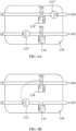
- FIG. 4A shows a flow adjuster 130 including hydraulic elements for adjusting pressure and/or flow.
- the flow adjuster 130 may include more or less elements than shown, for example, the flow adjuster 130 according to various embodiments, may have only one pump 132' or 132", or two pumps.
- FIG. 4A shows that, connected to the regenerator inlet 102, the flow adjuster 130 may include a dampener 134' and a first pressure sensor PS1, and a first pump 132' connected in series with the dampener.
- FIG. 4A further shows that, connected to the regenerator outlet 104, the flow adjuster 130 may include a dampener 134" and a second pressure sensor PS2, and a second pump 132" connected in series with the dampener.
- the first pump 132' may be started when the pressure measured by the first pressure sensor PS 1 is below a first threshold, and stopped when the pressure is over that threshold.
- the controlling of the first pump may be electronically, electric, pneumatic, or a combination thereof.
- Alternativeley or in addition the second pump 132" may be started when the pressure measured by the second pressure sensor PS2 is below a second threshold, and stopped when the pressure is over that threshold.
- the controlling of the second pump may be electronically, electric, pneumatic, or a combination thereof.
- only one pump is used (for example either 132' or 132") and the pump is controlled according to the pressure measured by the first pressure sensor PS1, the pressure measured by the second pressure sensor PS2, a filling level of the dampener 134', a filling level of the dampener dampener 134", according to a state depending on the first pressure and of the second pressure, according to a state depending on the filling level of the dampener 134' and the dampener 134".
- the flow adjuster 130 may include a reservoir connected to the regenerator inlet 102 (not shown in FIG. 4A ).
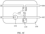
- FIG. 4B shows another flow adjuster 130 including hydraulic elements for adjusting pressure and/or flow.
- the flow adjuster 130 may include more or less elements than shown.
- the flow adjuster 130 may include a reservoir 135 connected to the regenerator inlet 102.
- the reservoir may ensure that a pressure of the regenerator inlet 102 is essentially zero, thus the inlet 102 is connectable a drain of a dialysis apparatus without any further modification.
- the reservoir 135 may also accommodate excess of dialysate, and may have a capacity (in volume) of up to 5L.
- the flow adjuster 130 may include a pump 132.
- FIG. 4B shows that, connected to the regenerator outlet 104, the flow adjuster 130 may include a dampener 134 and a pressure sensor PS2.
- the pump 132 may be started when the pressure measured by the pressure sensor PS2 is below a first threshold (e.g., below 7kPa), and stopped when the pressure is over that threshold.
- the controlling of the first pump may be electronically, electric, pneumatic, or a combination thereof.
- the flow adjuster 130 may alternatively include a reservoir 134 connected to the regenerator outlet 104.
- the reservoir may ensure that a pressure of the regenerator outlet 104 is essentially zero, thus the outlet 104 is connectable to the inlet of a dialysis apparatus without any further modification.
- the reservoir 134 may also accommodate excess of dialysate, and may have a capacity (in volume) of up to 5L.
- the flow adjuster 130 may include a pump 132.
- FIG. 4C shows that, connected to the regenerator inlet 102, the flow adjuster 130 may include a dampener 135 and a pressure sensor PS1.
- the pump 132 may be started when the pressure measured by the pressure sensor PS1 is above a first threshold (e.g., above 7kPa), and stopped when the pressure is below that threshold.
- the controlling of the first pump may be electronically, electric, pneumatic, or a combination thereof.
- the flow adjuster 130 may include a pressure sensor 136 to detect the external pressure at the one or both of the regenerator inlet 102 and the regenerator outlet 104, for example the pressure sensor 136 may include the pressure sensor PS1 and/or the pressure sensor PS2 illustrated in FIG. 3B .
- the flow adjuster 130 may be configured to adjust the internal flow or internal pressure based on the external pressure detected by the sensor 136.
- a dialysis apparatus connected to the regenerator inlet 102 and the regenerator outlet 104 sees flow impedances identical as in a comparative example wherein the dialysis apparatus is used with a dialysate dampener and a dialysate drain, thus within the normal operating parameters of the dialysis apparatus.
- FIGs. 5A, 5B , 6A, and 6B show different exemplary embodiments of housings 200 in accordance with various embodiments.
- the dialysate regenerator 100 may further include a housing 200.
- the housing 200 may include a base 220 and a counter portion 210 which may be releasably attachable to each other.
- the counter portion 210 may include a cartridge, that is attachable to the base.
- the housing 200 may include a lid 221, for example a hinged lid of which a hinged side is attached to the base and a side opposite to the hinged side is removably lockeable to the base 220.
- the counter portion 210 may include a cartridge which is held in place when the lid 221 is closed.
- the chamber 121 of the fluid portioning system 120 may include a reusable portion that is part of the base 220 and a replaceable portion that is part of the counter portion 210, for example, part of the cartridge.
- the reusable portion may be a pneumatic portion which parts do not contact the dialysate.
- the replaceable portion may be a hydraulic portion that contacts liquids such as the dialysate, and may be replaced, e.g., after one time use, after a pre-determined number of uses, after a predetermined time before first use, after a certain criterium is met, after a filter is full, after a infusate reservoir is empty, or a combination thereof.
- the fluid portioning system may be included in the counter portion of the housing, thus, the fluid portioning system is replaced when the counter portion is replaced.
- FIG. 5A and 5B show an example, wherein the counter portion 210 of the housing has the format of a cartridge that is attachable to the base 220.
- the counter portion 210 is attached to the base 220.
- the chamber 121 of the fluid portioning system 120 may include a counter part 212, included in the counter portion 210 and a base part 222, the base part being included in the base 220 of the housing 200.
- the counter part 212 and the base part 222 of the chamber 121 may be attached together when the counter portion 210 and the base 220 are attached to each other as shown in FIG. 5B .
- FIG. 5B As can be seen in FIG.
- the separator wall 122 may be disposed, e.g. attached, on the counter part 212 of the chamber, thereby being replaceable together with the counter portion 210.
- FIG. 5B shows the separator wall 122 in two positions, for the first state ST1 and the second state ST2 of which it may alternate.
- FIG. 6A and 6B show an example, wherein the counter portion 210 of the housing includes a cartridge that is attachable to the base 220.
- the cartridge may be secured to the base when the cover 221 is locked to the base, e.g., when the lid is closed.
- the counter portion 210 is attached to the base 220 and the housing 200 is closed.
- the cover 221 may be a lid, the lid may be hinged on the base on one side and lockable to the base on an opposite side.
- the chamber 121 of the fluid portioning system 120 may include a counter part 212, included in the cartridge.
- the chamber 121 of the fluid portioning system 120 may further include a base part 222, the base part 222 being included in the base 220 of the housing 200.
- the counter part 212 and the base part 222 of the chamber 121 may be attached together and secured together when the housing is closed as shown in FIG. 6B .
- the separator wall 122, or a layer thereof may be disposed, e.g. attached, on the counter part 212 of the chamber, thereby being replaceable together with the cartridge.
- the fluid portioning system may be included in the counter portion of the housing, thus, the fluid portioning system is replaced when the counter portion is replaced.
- the separator wall 122 may be a membrane.
- the membrane may be pre-shaped and may be flipable between a first membrane side being convex in the first state ST1 and a second side being convex in the second state ST2. Since the separator wall is a membrane, the side that is not convex in one of the states is concave.
- the counter part 212 of the chamber 121 may be included in a replaceable cartridge and the base 220 may be reusable.
- the movable separator wall 122 may be attached to the counter part 212 of the chamber 121 so that it may be retained in the counter portion 210 of the housing 200 or by the cartridge when the counter portion 210 or the cartridge is released from the base 220 of the housing 200.
- FIG. 7A illustrates the fluid portioning system 120 including 2 compartments, a first compartment 124 and second compartment 126, as can be seen in the cross sectional view A-A' in a resting position.
- the two compartments may be formed by two bags, each bag connected to one of the to the first and second openings 128, 129. Each of the two bags may be flexible so that its volume can be changed while the total volume of the two compartments remains constant.
- the fluid portioning system 120 may include an outer casing 121 which may be rigid, thereby limiting the total volume of the two compartments. A maximum volume of a compartments is achieved when the other compartments has a minimum volume (i.e., is completely empty).
- the two bags may be individual and separated bags, that may or may not have been joined, e.g. by welding them together.
- the two bags may be formed by welding 3 sheets together, so that the first bag is formed between a first sheet and a second sheet (middle sheet) and a second bag is formed between the second sheet and a third sheet.
- the separator wall 122 is formed by the second sheet.
- FIG. 7B shows the cross section A-A' at the end of two states, in the second state ST2, the second compartment 126 is full and essentially occupies all the volume of the fluid portioning system 120 and the first compartment 124 is empty and has substantially zero volume.
- the first state ST1 the first compartment 124 is full and essentially occupies all the volume of the fluid portioning system 120 and the second compartment 126 is empty and has substantially zero volume.
- the first compartment may include a first bag fluidly connected to the first opening 128 and wherein the separator wall 122 may be a wall of the first bag. At least a portion of the separator wall, for example only the first bag, may be included in the counter portion 210 of the housing 200 or cartridge.
- the second compartment may include a second bag fluidly connected to the second opening 129 and wherein the separator wall 122 may be a wall of the second bag, or a combination of the above, in which the wall of the first bag and the wall of the second bag contact each other and form the separator wall 122. At least a portion of the separator wall, for example the second bag, may be included in the counter portion 210 of the housing 200 or cartridge.
- the first compartment may include a first bag fluidly connected to the first opening 128 and the second compartment may include a second bag fluidly connected to the second opening 129 and the wall of the first bag and the wall of the second bag contact each other and form the separator wall 122.
- At least a portion of the separator wall, for example the first bag, may be included in the counter portion 210 of the housing 200 or cartridge.
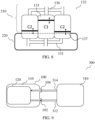
- FIG. 8 is a schematic drawing used for illustration purposes, however a pump in accordance with various embodiments is not limited thereto.
- the flow adjuster 130 may include a pump 132 (e.g. pump 132' or 132" as explained in connection with FIG. 4 ) to increase pressure.
- a pump 132 e.g. pump 132' or 132" as explained in connection with FIG. 4
- the pump 132 may include two pump chambers C1, C2 that may be configured, e.g., via one way valves and a pneumatic control system to alternately allow inflow of dialysate and to pump the dialysate out through an opening of a corresponding pump chamber.
- the pump 132 may be pneumatic and to pump the dialysate may include applying pneumatic pressure on a side of a moveable pump wall that is opposite to a dialysate contacting side, for each of the two pump chambers C1, C2.
- the pump 132 may be connected to the housing 200.
- the housing 200 may include a counter portion 210 and a base 220 which may be releasably attachable to each other.
- one of the two pump chambers C2 may be divided into two chambers connected in parallel 131 to a pneumatic pressure receiving side.
- a hydraulic side of the two chambers may be connected in parallel 136 as well thus working as a single pump chamber C2.
- the two chambers may be disposed on opposite sides of the other one of the two pump chambers C1, so that tension applied to the housing 200 during pumping by one of the two pump chambers C1, C2 may be symmetrically at least partially distributed to the other one of the two pump chambers C2, C1. Thereby shear stress on the housing and/or pump may be reduced and longevity of the base may be increased.
- the pneumatic pressure receiving side of the one of the two pump chambers and a further pneumatic pressure receiving side of the other one of the two pump chambers may be disposed on the base 220.
- a line 137 may indicate the separation where both parts of the pump chambers meet.
- the base 220 may be reusable and may include control elements, e.g., pneumatic and/or electronic control elements.
- the counter portion 210 may include disposable elements hydraulic circuit elements, e.g. all components of which a surface contacts dialysate.
- the base 220 may be reusable.
- the counter portion 210 of the housing 200 may include a replaceable, e.g., single use cartridge.
- the housing 200 may further include a cover 221, e.g, a lid. The lid may be hinge connected and may secure the cartridge onto the base.
- the dialysate regenerator may include a purification means, which may be, for example, a toxin removal means, and exemplified by a purification compartment.
- a purification means may refer to a compartment that can contain one or more sorbent materials.
- the purification means may also include electro-oxidation means, electro-dialysis means or other purification means that are not based on sorbent technology.
- the compartment can be connected to a dialysate flow path.
- the sorbent materials in the purification means are used for removing specific solutes from solution, such as urea.
- the purification meanscan have a single compartmental design wherein all sorbent materials necessary for performing dialysis are contained within the single compartment.
- the purification meanscan have a modular design wherein the sorbent materials are dispersed across at least two different modules, which can be connected to form a unitary body.
- the purification meansin the present disclosure may be a disposable purification means.
- the hydraulic circuit 110 may further include a sorbent cartridge.
- the hydraulic circuit 110 may further include at least one reversible retainer including an ion reservoir. A direction of the dialysate flow through the reversible retainer may be reversible.
- the dialysate regenerator may include one or more valves for alternating the dialysate flow path between a first flow phase from the dialysate inlet to the temporary storage volume via the reversible retainer; and a second flow phase from the via the temporary storage volume to the dialysate outlet via the purification means and the reversible retainer, wherein a direction of the dialysate flow path through the reversible retainer in the second flow phase is reverse to the direction of the dialysate flow path through the reversible retainers in the first flow phase.
- the dialysate regenerator may include a first reversible retainer upstream of the purification means and a second reversible retainer downstream of the purification means.
- the dialysate regenerator may include one or more valves for alternating the direction of the dialysate flow path through the reversible retainer between a first direction and a second direction, the second direction being reverse to the first direction of the dialysate flow path through the reversible retainer.
- the ion reservoir may be any chemical compound capable of retaining and releasing ions. Examples of such compounds may be an ion exchanger, an ion exchange membrane, an ion rejection membrane, etc.
- the retaining and releasing of the ions may be influenced by parameters of the dialysate, for example, by the pH value, the temperature, the pressure, the concentration, the toxin or electrolyte concentration, the density and the viscosity.
- the ion reservoir retains and releases ions dependent of the pH value.
- the term 'ion' when used in connection with the ion reservoir may refer to a charged atom or molecule.
- the ion may be a cation.
- the ion may be a cationic atom.
- the ion may be a physiologically essential ion.
- the ion may comprise a cation of the second group of the periodic table.
- the essential ion since it is selected from the second group of the periodic table, it has a higher valence than, for example, a cation from the first group of the periodic table.
- the higher valence affects that the cation having a higher valence may have a greater affinity for the ion reservoir or the ion exchanger contained in the reversible retainer.
- the ion may comprise calcium.
- the ion may comprise magnesium.
- the ion may comprise potassium.
- the ions, such as calcium, magnesium and potassium, may be termed essential ions, due to their physiological relevance.
- FIG. 9 shows a schematic of a dialysis system 300 in accordance with various embodiments.
- a dialysis system 300 may include a dialysis apparatus 310 and the dialysate regenerator 100 in accordance with various embodiments.
- a dialysis apparatus 310 may include a fresh dialysate input 314 and a spent dialysate output 312.
- the regenerator inlet 102 may be coupled to the spent dialysate output 312 for receiving spent dialysate
- the regenerator outlet 104 may be coupled to the fresh dialysate input 314 for dispensing regenerated dialysate.
- dialysate regeneration may be provided without any alteration to an existing dialysis apparatus.
- the dialysate regenerator includes a fluid portioning system, which is based on the principle of partitioning a dialysate flow of unknown flow rate into aliquots of known volume ('Dialysate Dose Volume'), and optionally mixing each aliquot with a defined volume of infusate ('Infusate Dose Volume').
- the aliquots may be determined with the help of the fluid portioning system, for example, a chamber (e.g., a rigid chamber) containing two distinct compartments (the first compartment and the second compartment), which are separated by a movable separator wall, such as a flexible membrane.
- a chamber e.g., a rigid chamber
- the separator wall can be moved to either side of the rigid chamber such that the volume of the individual compartments can vary between zero and the entire volume of the chamber.
- the sum of the volumes of both compartments is always equal to the volume of the chamber (the ⁇ Dialysate Dose Volume').
- the system can be present in two alternated states, the first state ST1 and the second state ST2.
- first state ST1 fluid flow is guided into the first compartment via the first opening, thus displacing fluid contained in the second compartment and forcing it to leave the chamber via the second opening.
- first compartment fills the entire chamber (i.e. the second compartment is empty)
- first chamber now contains exactly one aliquot volume of fluid, equal to the volume of the rigid chamber.
- the pressure increase may be detected by a pressure sensor, and may further be used to switch an inverting valve arrangement, e.g. consisting of one 3-way valve or two 2-way valves connected to either opening of the rigid chamber.
- the valves may be controlled pneumatically or electromechanically (e.g. using solenoids or servos).
- the switching of the valve assembly puts the system into the second state ST2: the fluid flow direction is inverted such that fluid is directed into the second compartment through the second opening of the chamber, while the fluid contained in the first compartment (corresponding to one aliquot equal to the volume of the rigid chamber) is drained through the first opening.
- the system then remains in this state until a renewed increase of fluid pressure indicates that the first compartment is completely emptied, and the second compartment now contains exactly one aliquot equal to the volume of the chamber.
- the inverting valve assembly is switched again, and the process continues again in the first state ST1. This action allows dividing a flowing fluid of unknown flow rate into uniform aliquot volumes, which each are equal to the volume of the chamber.
- a chamber e.g. a rigid chamber
- a movable separator wall wherein each compartment is connected to a separate opening in the chamber, allowing infusate to flow into or out of the compartment.
- An inverting valve arrangement e.g., including one 3-way valve or two 2-way valves at either opening of the rigid chamber can again be present in two alternating positions, which are switched in correspondence to the two possible states described above.
- the pressure of the infusate solution must be higher than the pressure in the fluid line into which the contents of the other compartment is dispensed. This can easily be achieved, for example, by providing infusate solution from a closed reservoir container, which is pressurised with air pressure.
- the infusate dose volume may also be used to dispense a volume of infusate solution, and concurrently drain an equivalent volume of excess dialysate.
- a first state of the system will see the filling of a first compartment with dialysis fluid taken from a point immediately upstream of the sorbent compartment, where the fluid pressure is high.
- the second compartment includes infusate solution, which is dispensed to the purified dialysate, using the high pressure in the first compartment as driving force.
- the driving force for this filling can either come from gravity (hydrostatic pressure between infusate container and drain container), or again from pressurising a closed infusate solution reservoir.
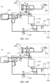
- FIGS. 10A and 10B show exemplary schematics according to embodiment 1 in the first state ST1 ( FIG. 10A ) and in the second state ST2 ( FIG. 10B ).
- the regenerator inlet 102 allows for receiving used dialysate, e.g., from a dialysis apparatus, which may be stored in a dialysate reservoir 135.
- the external pressure at the regenerator inlet 102 may be within the range from 0 to P1, for example, P1 may be 7kPa.
- the dialysate may pass a sorbent, e.g., in a sorbent cartridge 123.
- a pump 132 may increase the pressure of the dialysate after the reservoir.
- the pump may be controlled according to the external pressure PS2 of the regenerator outlet 104, for example, so that the external pressure PS2 of the regenerator outlet 104 is in the range from 0 and P1.
- Another dampener may be disposed downstream from the sorbent cartridge 123 and may measure a pressure PS 1 of a selected input of the chamber 121 of the fluid portioning system, which in the first state ST1 may be compartment 1 which is being filled, while the other compartment 2 is being emptied.
- the selection of chambers may be carried out by valves, for example, the illustrated 3 way valves V1 and V2.
- the pressure sensor PS1 registers an increase in pressure, which increase may trigger the switching of an inverting valve arrangement, such as 3-way valves V1 and V2, into the second state ST2 as shown in FIG. 10B , wherein compartment 1 is being emptied, while the other compartment 2 is being filled.
- an inverting valve arrangement such as 3-way valves V1 and V2
- the dampener with the pressure sensor PS2 may be disposed downstream from the chamber 121 and the inverting valve arrangement.
- the dialysate regenerator may include an infusate doser which allows for mixing an additive (e.g. infusate) into the dialysate.
- the infusate doser 400 may include an infusate reservoir 435 and an infusate portioning system, including, e.g., an additional inverting valve arrangement, e.g., 3-way valves V3 and V4, and dual compartment portioning chamber 421.
- the dual compartment portioning chamber 421 and the additional inverting valve arrangement may be configured and controlled analogously as the chamber 121 and the inverting valve arrangement, with the difference that the infusate aliquot is smaller than the dialysate aliquot.
- a mixing ratio is determined by the volume ratio of the dialysate aliquot vs the infusate aliquot.
- FIG. 11 shows an exemplary valve control principle, in a plot of pressure against time, wherein pressure may be the pressure at the compartment being filled, for example PS 1 in FIG. 10A .
- pressure may be the pressure at the compartment being filled, for example PS 1 in FIG. 10A .
- pressure raises (exemplified with a raise to 200 from 100), at which point (marked by the vertical dotted lines) a switching of state occurs (ST1 ⁇ ST2).
- the exemplary chamber 121 of the fluid portioning system 120 or the additional chamber (for the additive dosing) may, in various embodiments, include, e.g., be made up from, two rigid half-shells, sandwiching a flexible diaphragm.
- the two compartments may include, e.g., be made of, two fluid bags (e.g. two parallel fluid bags sharing one common bag wall) contained in a rigid chamber.
- the latter arrangement further opens the possibility to construct the rigid chamber from a wall of the disposable cartridge, locking against a profile located on the surface of the base, e.g., non-disposable cradle.
- FIGS. 12A and 12B show an exemplary chamber 121 of the fluid portioning system 120.
- FIG. 12A shows the chamber 121 in assembled state
- FIG. 12B shows the exemplary chamber in exploded view.
- the chamber 121 may include a movable separator wall 122 separating the interior of the chamber 121 into a first compartment 124 and a second compartment 126.
- the chamber 121 may further include a first opening 128 for allowing exchange of dialysate to and from the first compartment 124.
- the chamber 121 may further include a second opening 129 for allowing exchange of dialysate to and from the second compartment 126.
- the additional chamber for the additive doser may be constructed in an identical or similar way, by adapting the volume as required.
- the inverting valve arrangement may be constructed from commercially available disposable 3-way taps, which mechanically engage with a servo motor on the non-disposable cradle.
- a membrane valve system with pneumatic pistons may be used to construct an inverting flow arrangement from 2-way membrane valves.
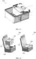
- FIGS. 13 and 14 show an example of a sorbent compartment in a cartridge as counter part 210 to the housing 200.
- the dialysate regeneration takes place in the sorbent compartment.
- the cartridge may include body, top cover, check valves, and filters.
- FIG. 14 shows an example of a base, e.g., cradle, which receives the cartridge and may include the lower portion of the pump.
- its top cover may be designed in such a way that it also forms the lower portions (or parts) of the chamber 121 and the additional chamber 421.
- the bottom side of the sorbent compartment may form the upper portion (or part) of the pump, e.g., upper portion of the bellow pump cavity.
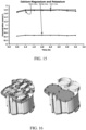
- FIG. 15 shows the in-vitro dialysate composition after re-infusion of Ca, Mg and K
- FIG. 16 and 17 shows the pneumatic elements, wherein a part is shown in FIG. 16 and a schematic is shown in FIG. 17 .
- the pump may include a force sensor which senses an internal pressure which may be used to detect whether the chamber (or compartment being filled) is full.
- the pressure sensor may be integrated in the wall of the pump chamber.
- the portioning system may include a force sensor which senses an internal pressure which may be used to detect whether the chamber (or compartment being filled) is full.
- the pressure sensor may be integrated in the wall of the chamber used for dosing.
- a hydraulic circuit valve design (V1, V2, V3 and V4) may be explained, in accordance with various embodiments.
- Each direction control valve (V1, V2, V3 and V4) in the integrated cartridge includes a rigid flow chamber, which is sealed by a flexible PVC membrane on one side (see, FIG. 18 and FIG. 19 ).
- the flow chamber had a fluid inlet channel and a fluid outlet channel.
- the inlet channel was located in close proximity to the flexible PVC membrane, such that pressing the flexible membrane onto the inlet channel opening could seal the channel.
- the pressing may be done with the help of pneumatic cylinders (one for each valve), which were equipped with silicone plungers.
- the valves are thus naturally open 2/2 valves, which can be closed by activating the pneumatic plungers.
- the optimum pressure setting for the pneumatic cylinder was determined for different fluid pressures and silicone plunger diameters.
- the preferred pneumatic cylinder was CJ2B6 from SMC as the size was deemed suitable in the whole integration design.
- the diameter of the valve inlet channel was 3 mm (Inner Diameter) and 6 mm (Outer Diameter).
- the test results are shown in the table 4 below: Silicone Disc Diameter ( ⁇ 8mm) Fluid flow pressure 0.6 bar 1.0 bar Cylinder pressure 2.0 bar 3.2 bar Silicone Disc Diameter ( ⁇ 7mm) Fluid flow pressure 0.6 bar 1.0 bar Cylinder pressure 1.8 bar 2.8 bar
- FIG. 20 shows a hydraulic flow diagram in which the portioning system and the pump are integrated into a dual pump.
- simulated purified dialysate (simulated dialysate after sorbent purification) was pumped through a resistor representing the flow resistance of an adsorber system, and was subsequently re-constituted with an actual infusate solution.
- the dose accuracy was evaluated by performing chemical analysis of collected 'fresh' dialysate at regular time intervals.
- FIG. 15 shows the in-vitro dialysate composition after re-infusion of Ca, Mg and K.
- the experiments have demonstrated the achievable accuracy and consistency of the proportioning system. The average proportioning ratio was very close to the target, and individual aliquots were subject to relatively small variations.
- a complete prototype was constructed as explained in accordance with various embodiments and showed good results using dialysate in an animal model.
- a dialysate regeneration compartment for purification of spent dialysate, e.g., by removal of uremic toxins and other unwanted solutes.
- the regenerator is configured to regenerate dialysate collected from connected dialysis apparatuses.
- the regenerator itself is not configured to perform a dialysis treatment.
- Spent dialysate is collected from the connected dialysis apparatuses, and fresh (regenerated) dialysate is provided to the connected dialysis apparatuses at a rate dictated by the set flow rate of the connected dialysis apparatuses.
- the dialysate regeneration device performs this task fully autonomous and there is no need for electronic communication or control between the dialysate regenerator and the connected dialysis apparatuses.
- the dialysate regenerator is intended to be used as an accessory to conventional dialysis apparatuses, extending their field of use to sorbent regenerative dialysis without the need for modification of the conventional dialysis apparatuses. This significantly reduces the development effort and regulatory effort typically required for sorbent-based regenerative dialysis apparatuses.
- the regenerator may optionally include any combination of the following:
- the regeneration device has a volume of from 10 dL to 50 dL, for example from 20 dL to 30 dL and a dry weight of from 1 kg to 10 kg, for example from 2 kg to 6 kg.
- the fluid portioning system may include one or more of:
- the additive dispensing means may be controlled mechanically using the force of the increased fluid pressure (e.g. using a piston pump), or electronically using a pressure sensor, valves and electronic control means.
- the additive dispensing means may be constructed from an additional chamber, which is separated into two compartments by a movable separator wall, wherein each compartment is connected to a separate opening in the additional chamber, allowing additive to flow into or out of the compartment, valves connected to the two openings at the additional chamber, and means to switch the valves in dependence of the fluid pressure in the main fluid line.
- the uniform portions of fluid may be regenerated by passing them through individual sorbent compartments, additional filters or adsorber compartments
- the additional filters and adsorber compartments may be configured in a way suitable to allow fluid regeneration without the need for concentrate proportioning or additive dispensing means.
- the present disclosure allows a conversion of existing dialysis apparatuses into sorbent-based regenerative devices, freeing them from the key handicap of conventional dialysis apparatuses (e.g. HD), namely the requirement for large quantities of highly pure water or dialysate. This conversion is achieved without requiring major, or any, changes in the physical and electronic make-up of existing dialysis apparatuses.
- conventional dialysis apparatuses e.g. HD
- the dialysate regenerator acts as an accessory to existing dialysis apparatuses, collecting spent dialysate from the drain, regenerating it into fresh apparatus, and feeding this fresh dialysate back to the dialysis apparatus.
- the development efforts for the regenerator can be focused on optimizing the mechanisms of sorbent regeneration and/or electrolyte re-infusion only. This provides a shorter path to providing patients with HD need (e.g., home HD), than the development of a completely new dialysis apparatus.
- doctors, nurses and patients who are already familiar and comfortable with the existing apparatuses will have less hesitation to run these apparatuses in a sorbent-regenerative mode using the dialysate regenerator as an accessory device.
- the dialysate regenerator is able to universally interface with various dialysis apparatuses, including HD and PD machines.
- the dialysate regenerator can be based on established sorbent technology and provides an accelerated pathway to bringing this technology to the patient, combining it with the established safety of existing dialysis apparatuses.
Landscapes
- Chemical & Material Sciences (AREA)
- Health & Medical Sciences (AREA)
- Chemical Kinetics & Catalysis (AREA)
- Organic Chemistry (AREA)
- Heart & Thoracic Surgery (AREA)
- Urology & Nephrology (AREA)
- Emergency Medicine (AREA)
- Inorganic Chemistry (AREA)
- Analytical Chemistry (AREA)
- Anesthesiology (AREA)
- Public Health (AREA)
- Biomedical Technology (AREA)
- Hematology (AREA)
- Life Sciences & Earth Sciences (AREA)
- Animal Behavior & Ethology (AREA)
- General Health & Medical Sciences (AREA)
- Engineering & Computer Science (AREA)
- Veterinary Medicine (AREA)
- Vascular Medicine (AREA)
- External Artificial Organs (AREA)
- Thermotherapy And Cooling Therapy Devices (AREA)
- Respiratory Apparatuses And Protective Means (AREA)
- Gloves (AREA)
Claims (15)
- Ein Dialysat-Regenerator (100) zum Anschluss an eine Dialysevorrichtung, wobei der Dialysat-Regenerator (100) folgendes aufweisteinen Regeneratoreinlass (102) zur Aufnahme von Dialysat;einen Regeneratorauslass (104) zur Abgabe von regeneriertem Dialysat;einen hydraulischen Kreislauf (110), der zwischen dem Regeneratoreinlass (102) und dem Regeneratorauslass (104) angeschlossen ist, und ferner ein Flüssigkeitsportionierungssystem (120) aufweist, um einen Dialysatstrom in gleichmäßige Portionen für eine sequentielle Regeneration zu unterteilen,wobei die sequentielle Regeneration zwei abwechselnde Zustände (ST1, ST2) aufweist, die einen ersten Zustand (ST1) und einen zweiten Zustand (ST2) aufweisen, und dadurch gekennzeichnet, dass das Flüssigkeitsportionierungssystem (120) aufweist:eine Kammer (121) aufweisendeine bewegliche Trennwand (122), die das Innere der Kammer (121) in ein erstes Kompartiment (124) und ein zweites Kompartiment (126) trennt,eine erste Öffnung (128), die den Austausch von Dialysat in und aus dem ersten Kompartiment (124) ermöglicht;eine zweite Öffnung (129), die den Austausch von Dialysat in und aus dem zweiten Kompartiment (126) ermöglicht; undwobei das Flüssigkeitsportionierungssystem (120) so konfiguriert ist, dass es im ersten Zustand (ST1) einen Dialysatfluss vom Regeneratoreinlass (102) zu einem der ersten und zweiten Kompartimente (124, 126) und im zweiten Zustand (ST2) zu dem anderen der ersten und zweiten Kompartimente (126, 124) ermöglicht, wobei der Dialysateintritt in das eine Kompartiment (124, 126) eine Verschiebung der beweglichen Trennwand (122) und einen Dialysataustritt aus dem anderen Kompartiment (126, 124) bewirkt.
- Der Dialysat-Regenerator (100) nach Anspruch 1, wobei der hydraulische Kreislauf (110) ferner einen Durchflussregler (130) aufweist, der so konfiguriert ist, dass er einen externen Durchfluss oder einen externen Druck von einem oder beiden, dem Regeneratoreinlass (102) und dem Regeneratorauslass (104), erfasst und einen internen Durchfluss oder einen internen Druck so einstellt, dass der externe Durchfluss unverändert bleibt,
optional, wobei der Durchflussregler (130) einen Dämpfer (134, 135) zum Ausgleich vorübergehender Änderungen des Innendrucks aufweist, und/oder
wobei der Durchflussregler (130) einen Drucksensor (136) aufweist, um den Außendruck an einem oder beiden vom Regeneratoreinlass (102) und vom Regeneratorauslass (104) zu erfassen, und wobei der Durchflussregler (130) so konfiguriert ist, dass er den internen Durchfluss oder den internen Druck basierend auf den durch den Sensor (136) erfassten Außendruck einstellt. - Der Dialysat-Regenerator (100) nach Anspruch 2, der ferner ein Gehäuse (200) aufweist,wobei das Gehäuse (200) eine Basis (220) und einen Gegenabschnitt (210) aufweist, die lösbar aneinander befestigt werden können,wobei die Kammer (121) ein Basisteil (222) und ein Gegenstück (212) aufweist, wobei das Basisteil von der Basis (220) des Gehäuses (200) umfasst wird,wobei das Gegenstück (212) und das Basisteil (222) der Kammer (121) miteinander verbunden sind, wenn das Gegenstück (210) und das Basisteil (220) aneinander befestigt sind,optional, wobei das Gegenstück (212) der Kammer (121) von einer austauschbaren Patrone umfasst ist und die Basis (220) wiederverwendbar ist, und/oderwobei die bewegliche Trennwand (122) oder eine Schicht davon im Falle einer mehrschichtigen Trennwand an dem Gegenstück (212) der Kammer (121) befestigt ist.
- Der Dialysat-Regenerator (100) nach einem der Ansprüche 1 bis 3, wobei die Separatorwand (122) eine Membran ist.
- Der Dialysat-Regenerator (100) nach Anspruch 4, wobei die Membran vorgeformt ist und zwischen einer ersten Membranseite, die in dem ersten Zustand (ST1) konvex ist, und einer zweiten Seite, die in dem zweiten Zustand (ST2) konvex ist, umgeschaltet werden kann, oderwobei das erste Kompartiment einen ersten Beutel aufweist, der mit der ersten Öffnung (128) in Fluidverbindung steht, und wobei die Trennwand (122) eine Wand des ersten Beutels ist, oderdas zweite Fach einen zweiten Beutel umfasst, der mit der zweiten Öffnung (129) in Fluidverbindung steht, und wobei die Trennwand (122) eine Wand des zweiten Beutels ist,oder eine Kombination der obigen Möglichkeiten, wobei die Wand des ersten Beutels und die Wand des zweiten Beutels einander berühren und die Trennwand (122) bilden.
- Der Dialysat-Regenerator (100) nach Anspruch 2, wobei der Durchflussregler (130) eine Pumpe (132) zur Erhöhung des Drucks oder zur Erhöhung des internen Durchflusses aufweist.
- Der Dialysat-Regenerator (100) nach Anspruch 6, wobei die Pumpe (132) zwei Pumpenkammern (C1, C2) aufweist, die so konfiguriert sind, dass sie abwechselnd den Zufluss von Dialysat ermöglichen und das Dialysat durch eine Öffnung einer entsprechenden Pumpenkammer abpumpen,
optional, wobei die Pumpe (132) pneumatisch ist und Pumpen des Dialysats Anwendung von pneumatischem Druck auf eine Seite einer beweglichen Pumpenwand, die einer Dialysatkontaktseite gegenüberliegt, auf die entsprechende Pumpenkammer (C1, C2) aufweist. - Der Dialysat-Regenerator (100) nach Anspruch 7, ferner aufweisend ein Gehäuse (200), wobei die Pumpe (132) mit dem Gehäuse (200) verbunden ist und wobei das Gehäuse (200) einen Gegenabschnitt (210) und eine Basis (220) aufweist, die lösbar aneinander befestigt werden können.
- Der Dialysat-Regenerator (100) nach Anspruch 8, wobei eine der beiden Pumpenkammern (C2) in zwei Kammern unterteilt ist, die parallel (131) mit einer pneumatischen Druckaufnahmeseite verbunden sind, und wobei die beiden Kammern auf gegenüberliegenden Seiten der anderen der beiden Pumpenkammern (C1) angeordnet sind, so dass die beim Pumpen durch eine der beiden Pumpenkammern (C1, C2) auf das Gehäuse (200) aufgebrachte Spannung symmetrisch auf die andere der beiden Pumpenkammern (C2, C1) verteilt wird.
- Der Dialysat-Regenerator (100) nach Anspruch 9, wobei die pneumatische Druckaufnahmeseite der einen der beiden Pumpenkammern und eine weitere pneumatische Druckaufnahmeseite der anderen der beiden Pumpenkammern auf der Basis (220) angeordnet sind.
- Der Dialysat-Regenerator (100) nach einem der Ansprüche 3 bis 9, wobei die Basis (220) wiederverwendbar ist und Steuerelemente aufweist und der Gegenabschnitt (210) Einwegelemente aufweist.
- Der Dialysat-Regenerator (100) nach Anspruch 3 oder Anspruch 8, wobei die Basis (220) wiederverwendbar ist,
der Gegenabschnitt (210) des Gehäuses (200) eine austauschbare Patrone aufweist. - Der Dialysat-Regenerator (100) nach einem der vorhergehenden Ansprüche, welcher ferner eine Reinigungseinrichtung aufweist,optional ferner ein Regenerationskompartiment aufweist, das die Reinigungseinrichtung aufweist, und/oderwobei die Reinigungseinrichtung einen Adsorptionsfilter oder eine Sorptionsmittelpatrone oder beides aufweist, oder wobei der hydraulische Kreislauf (110) weiterhin aufweist:die Reinigungseinrichtung; undmindestens einen reversiblen Rückhalter aufweisend ein Ionenreservoir,wobei eine Richtung des Dialysatflusses durch den reversiblen Rückhalter reversibel ist.
- Der Dialysat-Regenerator (100) nach einem der vorhergehenden Ansprüche, welcher ferner einen Additiv-Dosierer (400) aufweist, der so konfiguriert ist, dass er ein Additiv in das Dialysat mischt, wobei der Additiv-Dosierer (400) optional ein Additiv-Portionierungssystem aufweist, das mit dem Flüssigkeitsportionierungssystem synchronisiert ist, das das Dialysat portioniert.
- Ein Dialyse-System (300) aufweisendeine Dialysevorrichtung (310), aufweisend:- einen Eingang für frisches Dialysat (314);- einen Ausgang für verbrauchtes Dialysat- (312); undden Dialysat-Regenerator (100) nach einem der Ansprüche 1 bis 14,wobei der Regeneratoreinlass (102) mit dem Ausgang für verbrauchtes Dialysat (312) verbunden ist, um verbrauchtes Dialysat aufzunehmen, und wobei der Regeneratorauslass (104) mit dem Eingang (314) für frisches Dialysat verbunden ist, um regeneriertes Dialysat abzugeben.
Applications Claiming Priority (4)
| Application Number | Priority Date | Filing Date | Title |
|---|---|---|---|
| SG10202003361W | 2020-04-13 | ||
| SG10202003363P | 2020-04-13 | ||
| SG10202003365X | 2020-04-13 | ||
| PCT/SG2021/050209 WO2021211061A1 (en) | 2020-04-13 | 2021-04-13 | Dialysate regenerator and system comprising the same |
Publications (3)
| Publication Number | Publication Date |
|---|---|
| EP4135789A1 EP4135789A1 (de) | 2023-02-22 |
| EP4135789C0 EP4135789C0 (de) | 2024-05-29 |
| EP4135789B1 true EP4135789B1 (de) | 2024-05-29 |
Family
ID=75639959
Family Applications (2)
| Application Number | Title | Priority Date | Filing Date |
|---|---|---|---|
| EP21721241.4A Active EP4135789B1 (de) | 2020-04-13 | 2021-04-13 | Dialysatregenerator und system damit |
| EP21720870.1A Active EP4135788B1 (de) | 2020-04-13 | 2021-04-13 | Dialysatregenerator mit umkehrbarem halter |
Family Applications After (1)
| Application Number | Title | Priority Date | Filing Date |
|---|---|---|---|
| EP21720870.1A Active EP4135788B1 (de) | 2020-04-13 | 2021-04-13 | Dialysatregenerator mit umkehrbarem halter |
Country Status (7)
| Country | Link |
|---|---|
| US (2) | US12485212B2 (de) |
| EP (2) | EP4135789B1 (de) |
| CN (2) | CN115916285B (de) |
| AU (2) | AU2021255746A1 (de) |
| CA (2) | CA3180135A1 (de) |
| ES (2) | ES2983106T3 (de) |
| WO (2) | WO2021211061A1 (de) |
Families Citing this family (2)
| Publication number | Priority date | Publication date | Assignee | Title |
|---|---|---|---|---|
| WO2023097256A1 (en) * | 2021-11-24 | 2023-06-01 | University Of Washington | Water-conserving hemodialysis systems and methods |
| CN116688270B (zh) * | 2023-04-27 | 2025-12-02 | 东南大学 | 一种双联齿轮泵送过滤系统 |
Citations (1)
| Publication number | Priority date | Publication date | Assignee | Title |
|---|---|---|---|---|
| EP2612684B1 (de) * | 2007-11-09 | 2016-12-07 | Baxter International Inc. | Dialysemaschine mit ausgeglichenem Fluss |
Family Cites Families (22)
| Publication number | Priority date | Publication date | Assignee | Title |
|---|---|---|---|---|
| US6627164B1 (en) | 2000-11-28 | 2003-09-30 | Renal Solutions, Inc. | Sodium zirconium carbonate and zirconium basic carbonate and methods of making the same |
| US7241272B2 (en) | 2001-11-13 | 2007-07-10 | Baxter International Inc. | Method and composition for removing uremic toxins in dialysis processes |
| US7435342B2 (en) * | 2003-12-24 | 2008-10-14 | Chemica Technologies, Inc. | Dialysate regeneration system for portable human dialysis |
| JP4653170B2 (ja) | 2004-06-09 | 2011-03-16 | リナル・ソリューションズ・インコーポレーテッド | 透析システム |
| SE532147C2 (sv) * | 2005-02-16 | 2009-11-03 | Triomed Ab | Bärbart dialyssystem |
| US8715221B2 (en) | 2006-03-08 | 2014-05-06 | Fresenius Medical Care Holdings, Inc. | Wearable kidney |
| SE532971C2 (sv) * | 2006-08-16 | 2010-05-25 | Triomed Ab | System för regenerering av en vätska |
| EP2219704B1 (de) | 2007-11-16 | 2018-08-29 | Fresenius Medical Care Holdings, Inc. | Dialysesysteme und verfahren |
| BRPI0915397B8 (pt) | 2008-06-23 | 2021-06-22 | Temasek Polytechnic | sorvente para um dispositivo de díalise |
| US8409444B2 (en) | 2008-09-30 | 2013-04-02 | Fresenius Medical Care Holdings, Inc. | Acid zirconium phosphate and alkaline hydrous zirconium oxide materials for sorbent dialysis |
| MX354635B (es) * | 2009-09-08 | 2018-03-14 | Fresenius Medical Care Holdings Inc | Sistema de diálisis peritoneal. |
| GB201019228D0 (en) | 2010-11-15 | 2010-12-29 | Corp | Dialysis device and method of dialysis |
| EP3165245B1 (de) | 2011-08-02 | 2019-02-20 | Medtronic, Inc. | Hämodialysesystem mit einem durchflussweg mit gesteuertem nachgiebigem volumen |
| US10857277B2 (en) | 2011-08-16 | 2020-12-08 | Medtronic, Inc. | Modular hemodialysis system |
| WO2013025957A1 (en) * | 2011-08-18 | 2013-02-21 | Fresenius Medical Care Holdings, Inc. | Sorbent and chemical regeneration of dialysate |
| US10905816B2 (en) * | 2012-12-10 | 2021-02-02 | Medtronic, Inc. | Sodium management system for hemodialysis |
| US20140158588A1 (en) | 2012-12-10 | 2014-06-12 | Medtronic, Inc. | pH AND BUFFER MANAGEMENT SYSTEM FOR HEMODIALYSIS SYSTEMS |
| EP2950836B1 (de) | 2013-02-01 | 2019-11-06 | Medtronic, Inc. | Sorptionsmittelkartusche zur messung von lösungsmittelkonzentrationen |
| WO2015199767A1 (en) * | 2014-06-24 | 2015-12-30 | Medtronic, Inc. | Reserve zirconium phosphate module for use in sorbent dialysis |
| EP3827853A1 (de) | 2015-09-25 | 2021-06-02 | Medtronic, Inc. | Systeme und verfahren zur selektiven sorptionsmittelbasierten regenerationsdialyse |
| EP3548110B1 (de) * | 2016-12-05 | 2025-10-15 | Temasek Polytechnic | Sorptionsmittel für eine dialysevorrichtung und dialysesystem |
| CN106975115A (zh) * | 2017-03-09 | 2017-07-25 | 李建中 | 透析液再生装置、血液净化系统 |
-
2021
- 2021-04-13 CN CN202180042457.7A patent/CN115916285B/zh active Active
- 2021-04-13 CA CA3180135A patent/CA3180135A1/en active Pending
- 2021-04-13 AU AU2021255746A patent/AU2021255746A1/en active Pending
- 2021-04-13 US US17/918,825 patent/US12485212B2/en active Active
- 2021-04-13 US US17/918,818 patent/US12290621B2/en active Active
- 2021-04-13 ES ES21721241T patent/ES2983106T3/es active Active
- 2021-04-13 WO PCT/SG2021/050209 patent/WO2021211061A1/en not_active Ceased
- 2021-04-13 WO PCT/SG2021/050208 patent/WO2021211060A1/en not_active Ceased
- 2021-04-13 EP EP21721241.4A patent/EP4135789B1/de active Active
- 2021-04-13 ES ES21720870T patent/ES2983105T3/es active Active
- 2021-04-13 EP EP21720870.1A patent/EP4135788B1/de active Active
- 2021-04-13 CN CN202180042852.5A patent/CN115835893B/zh active Active
- 2021-04-13 CA CA3180137A patent/CA3180137A1/en active Pending
- 2021-04-13 AU AU2021255340A patent/AU2021255340A1/en active Pending
Patent Citations (1)
| Publication number | Priority date | Publication date | Assignee | Title |
|---|---|---|---|---|
| EP2612684B1 (de) * | 2007-11-09 | 2016-12-07 | Baxter International Inc. | Dialysemaschine mit ausgeglichenem Fluss |
Also Published As
| Publication number | Publication date |
|---|---|
| CN115835893A (zh) | 2023-03-21 |
| US12485212B2 (en) | 2025-12-02 |
| EP4135789A1 (de) | 2023-02-22 |
| WO2021211060A1 (en) | 2021-10-21 |
| WO2021211061A1 (en) | 2021-10-21 |
| CN115835893B (zh) | 2025-12-02 |
| US20240058514A1 (en) | 2024-02-22 |
| US20230347031A1 (en) | 2023-11-02 |
| CA3180135A1 (en) | 2021-10-21 |
| EP4135789C0 (de) | 2024-05-29 |
| ES2983106T3 (es) | 2024-10-22 |
| ES2983105T3 (es) | 2024-10-22 |
| AU2021255746A1 (en) | 2022-11-24 |
| CA3180137A1 (en) | 2021-10-21 |
| AU2021255340A1 (en) | 2022-11-17 |
| CN115916285B (zh) | 2025-08-26 |
| EP4135788C0 (de) | 2024-05-29 |
| EP4135788B1 (de) | 2024-05-29 |
| EP4135788A1 (de) | 2023-02-22 |
| CN115916285A (zh) | 2023-04-04 |
| US12290621B2 (en) | 2025-05-06 |
Similar Documents
| Publication | Publication Date | Title |
|---|---|---|
| US11235094B2 (en) | System for peritoneal dialysis | |
| US10080831B2 (en) | Dialysis systems, components, and methods | |
| EP4135789B1 (de) | Dialysatregenerator und system damit | |
| CN119215253A (zh) | 透析液再生系统及透析设备 |
Legal Events
| Date | Code | Title | Description |
|---|---|---|---|
| STAA | Information on the status of an ep patent application or granted ep patent |
Free format text: STATUS: UNKNOWN |
|
| STAA | Information on the status of an ep patent application or granted ep patent |
Free format text: STATUS: THE INTERNATIONAL PUBLICATION HAS BEEN MADE |
|
| PUAI | Public reference made under article 153(3) epc to a published international application that has entered the european phase |
Free format text: ORIGINAL CODE: 0009012 |
|
| STAA | Information on the status of an ep patent application or granted ep patent |
Free format text: STATUS: REQUEST FOR EXAMINATION WAS MADE |
|
| 17P | Request for examination filed |
Effective date: 20221114 |
|
| AK | Designated contracting states |
Kind code of ref document: A1 Designated state(s): AL AT BE BG CH CY CZ DE DK EE ES FI FR GB GR HR HU IE IS IT LI LT LU LV MC MK MT NL NO PL PT RO RS SE SI SK SM TR |
|
| DAV | Request for validation of the european patent (deleted) | ||
| DAX | Request for extension of the european patent (deleted) | ||
| GRAP | Despatch of communication of intention to grant a patent |
Free format text: ORIGINAL CODE: EPIDOSNIGR1 |
|
| STAA | Information on the status of an ep patent application or granted ep patent |
Free format text: STATUS: GRANT OF PATENT IS INTENDED |
|
| RIC1 | Information provided on ipc code assigned before grant |
Ipc: B01J 41/10 20060101ALI20231030BHEP Ipc: B01J 41/02 20060101ALI20231030BHEP Ipc: B01J 39/12 20060101ALI20231030BHEP Ipc: B01J 39/02 20060101ALI20231030BHEP Ipc: B01J 20/20 20060101ALI20231030BHEP Ipc: A61M 1/28 20060101ALI20231030BHEP Ipc: A61M 1/16 20060101AFI20231030BHEP |
|
| INTG | Intention to grant announced |
Effective date: 20231121 |
|
| GRAS | Grant fee paid |
Free format text: ORIGINAL CODE: EPIDOSNIGR3 |
|
| GRAA | (expected) grant |
Free format text: ORIGINAL CODE: 0009210 |
|
| STAA | Information on the status of an ep patent application or granted ep patent |
Free format text: STATUS: THE PATENT HAS BEEN GRANTED |
|
| AK | Designated contracting states |
Kind code of ref document: B1 Designated state(s): AL AT BE BG CH CY CZ DE DK EE ES FI FR GB GR HR HU IE IS IT LI LT LU LV MC MK MT NL NO PL PT RO RS SE SI SK SM TR |
|
| REG | Reference to a national code |
Ref country code: CH Ref legal event code: EP |
|
| REG | Reference to a national code |
Ref country code: IE Ref legal event code: FG4D |
|
| REG | Reference to a national code |
Ref country code: DE Ref legal event code: R096 Ref document number: 602021013843 Country of ref document: DE |
|
| U01 | Request for unitary effect filed |
Effective date: 20240610 |
|
| U07 | Unitary effect registered |
Designated state(s): AT BE BG DE DK EE FI FR IT LT LU LV MT NL PT SE SI Effective date: 20240619 |
|
| PG25 | Lapsed in a contracting state [announced via postgrant information from national office to epo] |
Ref country code: IS Free format text: LAPSE BECAUSE OF FAILURE TO SUBMIT A TRANSLATION OF THE DESCRIPTION OR TO PAY THE FEE WITHIN THE PRESCRIBED TIME-LIMIT Effective date: 20240929 |
|
| PG25 | Lapsed in a contracting state [announced via postgrant information from national office to epo] |
Ref country code: HR Free format text: LAPSE BECAUSE OF FAILURE TO SUBMIT A TRANSLATION OF THE DESCRIPTION OR TO PAY THE FEE WITHIN THE PRESCRIBED TIME-LIMIT Effective date: 20240529 |
|
| PG25 | Lapsed in a contracting state [announced via postgrant information from national office to epo] |
Ref country code: GR Free format text: LAPSE BECAUSE OF FAILURE TO SUBMIT A TRANSLATION OF THE DESCRIPTION OR TO PAY THE FEE WITHIN THE PRESCRIBED TIME-LIMIT Effective date: 20240830 |
|
| REG | Reference to a national code |
Ref country code: ES Ref legal event code: FG2A Ref document number: 2983106 Country of ref document: ES Kind code of ref document: T3 Effective date: 20241022 |
|
| PG25 | Lapsed in a contracting state [announced via postgrant information from national office to epo] |
Ref country code: PL Free format text: LAPSE BECAUSE OF FAILURE TO SUBMIT A TRANSLATION OF THE DESCRIPTION OR TO PAY THE FEE WITHIN THE PRESCRIBED TIME-LIMIT Effective date: 20240529 |
|
| PG25 | Lapsed in a contracting state [announced via postgrant information from national office to epo] |
Ref country code: PL Free format text: LAPSE BECAUSE OF FAILURE TO SUBMIT A TRANSLATION OF THE DESCRIPTION OR TO PAY THE FEE WITHIN THE PRESCRIBED TIME-LIMIT Effective date: 20240529 Ref country code: NO Free format text: LAPSE BECAUSE OF FAILURE TO SUBMIT A TRANSLATION OF THE DESCRIPTION OR TO PAY THE FEE WITHIN THE PRESCRIBED TIME-LIMIT Effective date: 20240829 Ref country code: IS Free format text: LAPSE BECAUSE OF FAILURE TO SUBMIT A TRANSLATION OF THE DESCRIPTION OR TO PAY THE FEE WITHIN THE PRESCRIBED TIME-LIMIT Effective date: 20240929 Ref country code: HR Free format text: LAPSE BECAUSE OF FAILURE TO SUBMIT A TRANSLATION OF THE DESCRIPTION OR TO PAY THE FEE WITHIN THE PRESCRIBED TIME-LIMIT Effective date: 20240529 Ref country code: GR Free format text: LAPSE BECAUSE OF FAILURE TO SUBMIT A TRANSLATION OF THE DESCRIPTION OR TO PAY THE FEE WITHIN THE PRESCRIBED TIME-LIMIT Effective date: 20240830 Ref country code: RS Free format text: LAPSE BECAUSE OF FAILURE TO SUBMIT A TRANSLATION OF THE DESCRIPTION OR TO PAY THE FEE WITHIN THE PRESCRIBED TIME-LIMIT Effective date: 20240829 |
|
| PG25 | Lapsed in a contracting state [announced via postgrant information from national office to epo] |
Ref country code: CZ Free format text: LAPSE BECAUSE OF FAILURE TO SUBMIT A TRANSLATION OF THE DESCRIPTION OR TO PAY THE FEE WITHIN THE PRESCRIBED TIME-LIMIT Effective date: 20240529 |
|
| PG25 | Lapsed in a contracting state [announced via postgrant information from national office to epo] |
Ref country code: SK Free format text: LAPSE BECAUSE OF FAILURE TO SUBMIT A TRANSLATION OF THE DESCRIPTION OR TO PAY THE FEE WITHIN THE PRESCRIBED TIME-LIMIT Effective date: 20240529 Ref country code: RO Free format text: LAPSE BECAUSE OF FAILURE TO SUBMIT A TRANSLATION OF THE DESCRIPTION OR TO PAY THE FEE WITHIN THE PRESCRIBED TIME-LIMIT Effective date: 20240529 |
|
| PG25 | Lapsed in a contracting state [announced via postgrant information from national office to epo] |
Ref country code: SM Free format text: LAPSE BECAUSE OF FAILURE TO SUBMIT A TRANSLATION OF THE DESCRIPTION OR TO PAY THE FEE WITHIN THE PRESCRIBED TIME-LIMIT Effective date: 20240529 |
|
| PG25 | Lapsed in a contracting state [announced via postgrant information from national office to epo] |
Ref country code: SM Free format text: LAPSE BECAUSE OF FAILURE TO SUBMIT A TRANSLATION OF THE DESCRIPTION OR TO PAY THE FEE WITHIN THE PRESCRIBED TIME-LIMIT Effective date: 20240529 Ref country code: SK Free format text: LAPSE BECAUSE OF FAILURE TO SUBMIT A TRANSLATION OF THE DESCRIPTION OR TO PAY THE FEE WITHIN THE PRESCRIBED TIME-LIMIT Effective date: 20240529 Ref country code: RO Free format text: LAPSE BECAUSE OF FAILURE TO SUBMIT A TRANSLATION OF THE DESCRIPTION OR TO PAY THE FEE WITHIN THE PRESCRIBED TIME-LIMIT Effective date: 20240529 Ref country code: CZ Free format text: LAPSE BECAUSE OF FAILURE TO SUBMIT A TRANSLATION OF THE DESCRIPTION OR TO PAY THE FEE WITHIN THE PRESCRIBED TIME-LIMIT Effective date: 20240529 |
|
| PLBE | No opposition filed within time limit |
Free format text: ORIGINAL CODE: 0009261 |
|
| STAA | Information on the status of an ep patent application or granted ep patent |
Free format text: STATUS: NO OPPOSITION FILED WITHIN TIME LIMIT |
|
| U20 | Renewal fee for the european patent with unitary effect paid |
Year of fee payment: 5 Effective date: 20250326 |
|
| 26N | No opposition filed |
Effective date: 20250303 |
|
| PGFP | Annual fee paid to national office [announced via postgrant information from national office to epo] |
Ref country code: ES Payment date: 20250528 Year of fee payment: 5 |
|
| REG | Reference to a national code |
Ref country code: CH Ref legal event code: H13 Free format text: ST27 STATUS EVENT CODE: U-0-0-H10-H13 (AS PROVIDED BY THE NATIONAL OFFICE) Effective date: 20251125 |
|
| PG25 | Lapsed in a contracting state [announced via postgrant information from national office to epo] |
Ref country code: MC Free format text: LAPSE BECAUSE OF FAILURE TO SUBMIT A TRANSLATION OF THE DESCRIPTION OR TO PAY THE FEE WITHIN THE PRESCRIBED TIME-LIMIT Effective date: 20240529 |
|
| PG25 | Lapsed in a contracting state [announced via postgrant information from national office to epo] |
Ref country code: CH Free format text: LAPSE BECAUSE OF NON-PAYMENT OF DUE FEES Effective date: 20250430 |
|
| PGFP | Annual fee paid to national office [announced via postgrant information from national office to epo] |
Ref country code: GB Payment date: 20260313 Year of fee payment: 6 |
|
| PG25 | Lapsed in a contracting state [announced via postgrant information from national office to epo] |
Ref country code: IE Free format text: LAPSE BECAUSE OF NON-PAYMENT OF DUE FEES Effective date: 20250413 |
|
| U20 | Renewal fee for the european patent with unitary effect paid |
Year of fee payment: 6 Effective date: 20260313 |