EP4135863B1 - Spielkastenelement, das den deckel eines spielkastens oder spielbretts bildet, dazugehöriger spielkasten - Google Patents
Spielkastenelement, das den deckel eines spielkastens oder spielbretts bildet, dazugehöriger spielkasten Download PDFInfo
- Publication number
- EP4135863B1 EP4135863B1 EP21718140.3A EP21718140A EP4135863B1 EP 4135863 B1 EP4135863 B1 EP 4135863B1 EP 21718140 A EP21718140 A EP 21718140A EP 4135863 B1 EP4135863 B1 EP 4135863B1
- Authority
- EP
- European Patent Office
- Prior art keywords
- game
- board
- box
- walls
- cover
- Prior art date
- Legal status (The legal status is an assumption and is not a legal conclusion. Google has not performed a legal analysis and makes no representation as to the accuracy of the status listed.)
- Active
Links
Images







Classifications
-
- A—HUMAN NECESSITIES
- A63—SPORTS; GAMES; AMUSEMENTS
- A63F—CARD, BOARD, OR ROULETTE GAMES; INDOOR GAMES USING SMALL MOVING PLAYING BODIES; VIDEO GAMES; GAMES NOT OTHERWISE PROVIDED FOR
- A63F3/00—Board games; Raffle games
- A63F3/00895—Accessories for board games
-
- A—HUMAN NECESSITIES
- A63—SPORTS; GAMES; AMUSEMENTS
- A63F—CARD, BOARD, OR ROULETTE GAMES; INDOOR GAMES USING SMALL MOVING PLAYING BODIES; VIDEO GAMES; GAMES NOT OTHERWISE PROVIDED FOR
- A63F3/00—Board games; Raffle games
- A63F3/00173—Characteristics of game boards, alone or in relation to supporting structures or playing piece
- A63F3/0023—Foldable, rollable, collapsible or segmented boards
-
- B—PERFORMING OPERATIONS; TRANSPORTING
- B65—CONVEYING; PACKING; STORING; HANDLING THIN OR FILAMENTARY MATERIAL
- B65D—CONTAINERS FOR STORAGE OR TRANSPORT OF ARTICLES OR MATERIALS, e.g. BAGS, BARRELS, BOTTLES, BOXES, CANS, CARTONS, CRATES, DRUMS, JARS, TANKS, HOPPERS, FORWARDING CONTAINERS; ACCESSORIES, CLOSURES, OR FITTINGS THEREFOR; PACKAGING ELEMENTS; PACKAGES
- B65D5/00—Rigid or semi-rigid containers of polygonal cross-section, e.g. boxes, cartons or trays, formed by folding or erecting one or more blanks made of paper
- B65D5/32—Rigid or semi-rigid containers of polygonal cross-section, e.g. boxes, cartons or trays, formed by folding or erecting one or more blanks made of paper having bodies formed by folding and interconnecting two or more blanks
- B65D5/322—Rigid or semi-rigid containers of polygonal cross-section, e.g. boxes, cartons or trays, formed by folding or erecting one or more blanks made of paper having bodies formed by folding and interconnecting two or more blanks at least one container body part formed by folding a single blank to essentially U-shape with or without extensions which form openable lid elements
-
- B—PERFORMING OPERATIONS; TRANSPORTING
- B65—CONVEYING; PACKING; STORING; HANDLING THIN OR FILAMENTARY MATERIAL
- B65D—CONTAINERS FOR STORAGE OR TRANSPORT OF ARTICLES OR MATERIALS, e.g. BAGS, BARRELS, BOTTLES, BOXES, CANS, CARTONS, CRATES, DRUMS, JARS, TANKS, HOPPERS, FORWARDING CONTAINERS; ACCESSORIES, CLOSURES, OR FITTINGS THEREFOR; PACKAGING ELEMENTS; PACKAGES
- B65D81/00—Containers, packaging elements, or packages, for contents presenting particular transport or storage problems, or adapted to be used for non-packaging purposes after removal of contents
- B65D81/36—Containers, packaging elements, or packages, for contents presenting particular transport or storage problems, or adapted to be used for non-packaging purposes after removal of contents adapted to be used for non-packaging purposes after removal of contents
-
- A—HUMAN NECESSITIES
- A63—SPORTS; GAMES; AMUSEMENTS
- A63F—CARD, BOARD, OR ROULETTE GAMES; INDOOR GAMES USING SMALL MOVING PLAYING BODIES; VIDEO GAMES; GAMES NOT OTHERWISE PROVIDED FOR
- A63F3/00—Board games; Raffle games
- A63F3/00173—Characteristics of game boards, alone or in relation to supporting structures or playing piece
- A63F3/0023—Foldable, rollable, collapsible or segmented boards
- A63F2003/00246—Foldable, rollable, collapsible or segmented boards with three or more hinges or folds
- A63F2003/00252—Foldable, rollable, collapsible or segmented boards with three or more hinges or folds perpendicular
-
- A—HUMAN NECESSITIES
- A63—SPORTS; GAMES; AMUSEMENTS
- A63F—CARD, BOARD, OR ROULETTE GAMES; INDOOR GAMES USING SMALL MOVING PLAYING BODIES; VIDEO GAMES; GAMES NOT OTHERWISE PROVIDED FOR
- A63F3/00—Board games; Raffle games
- A63F3/00173—Characteristics of game boards, alone or in relation to supporting structures or playing piece
- A63F3/00261—Details of game boards, e.g. rotatable, slidable or replaceable parts, modular game boards, vertical game boards
- A63F2003/00359—Modular units
- A63F2003/00362—Modular units with connections between modules
- A63F2003/00391—Modular units with connections between modules magnetic
-
- A—HUMAN NECESSITIES
- A63—SPORTS; GAMES; AMUSEMENTS
- A63F—CARD, BOARD, OR ROULETTE GAMES; INDOOR GAMES USING SMALL MOVING PLAYING BODIES; VIDEO GAMES; GAMES NOT OTHERWISE PROVIDED FOR
- A63F3/00—Board games; Raffle games
- A63F3/00895—Accessories for board games
- A63F2003/00943—Box or container for board games
- A63F2003/00952—Box or container for board games with a drawer
-
- A—HUMAN NECESSITIES
- A63—SPORTS; GAMES; AMUSEMENTS
- A63F—CARD, BOARD, OR ROULETTE GAMES; INDOOR GAMES USING SMALL MOVING PLAYING BODIES; VIDEO GAMES; GAMES NOT OTHERWISE PROVIDED FOR
- A63F3/00—Board games; Raffle games
- A63F3/00895—Accessories for board games
- A63F2003/00943—Box or container for board games
- A63F2003/00955—Box or container for board games with a lid
- A63F2003/00962—Box or container for board games with a lid with a game board on the lid or the inside of the lid
-
- A—HUMAN NECESSITIES
- A63—SPORTS; GAMES; AMUSEMENTS
- A63F—CARD, BOARD, OR ROULETTE GAMES; INDOOR GAMES USING SMALL MOVING PLAYING BODIES; VIDEO GAMES; GAMES NOT OTHERWISE PROVIDED FOR
- A63F2250/00—Miscellaneous game characteristics
- A63F2250/60—Connection between elements not otherwise provided for
- A63F2250/601—Connection between elements not otherwise provided for with hook and loop-type fastener
-
- B—PERFORMING OPERATIONS; TRANSPORTING
- B65—CONVEYING; PACKING; STORING; HANDLING THIN OR FILAMENTARY MATERIAL
- B65D—CONTAINERS FOR STORAGE OR TRANSPORT OF ARTICLES OR MATERIALS, e.g. BAGS, BARRELS, BOTTLES, BOXES, CANS, CARTONS, CRATES, DRUMS, JARS, TANKS, HOPPERS, FORWARDING CONTAINERS; ACCESSORIES, CLOSURES, OR FITTINGS THEREFOR; PACKAGING ELEMENTS; PACKAGES
- B65D2313/00—Connecting or fastening means
- B65D2313/02—Connecting or fastening means of hook-and-loop type
-
- B—PERFORMING OPERATIONS; TRANSPORTING
- B65—CONVEYING; PACKING; STORING; HANDLING THIN OR FILAMENTARY MATERIAL
- B65D—CONTAINERS FOR STORAGE OR TRANSPORT OF ARTICLES OR MATERIALS, e.g. BAGS, BARRELS, BOTTLES, BOXES, CANS, CARTONS, CRATES, DRUMS, JARS, TANKS, HOPPERS, FORWARDING CONTAINERS; ACCESSORIES, CLOSURES, OR FITTINGS THEREFOR; PACKAGING ELEMENTS; PACKAGES
- B65D2313/00—Connecting or fastening means
- B65D2313/04—Connecting or fastening means of magnetic type
Definitions
- the invention relates to a board game box, in particular comprising a lid which can be used as a game board and a tray for storing board game equipment such as playing cards.
- a board game box allows you to store board game materials such as playing cards, one or more dice(s), a game board, etc.
- card games In addition, in the case of games using cards, it is often necessary to be able to store them properly so as not to deteriorate them. Finally, card games often require a card holder or card dispenser to facilitate access to cards by players.
- the invention proposes a game element, preferably a game box which can serve as a cover, a game mat and as well as a game box comprising such an element.
- the invention proposes a game box comprising a storage bin for the game material and a lid which can be transformed into a game mat.
- the lid being transformable, the size of the box is smaller than a box which would have been necessary for at least store the play mat.
- the invention proposes a board game box comprising: a tray adapted to contain board game equipment; an element according to the first aspect of the invention forming a cover for said tray or board game board.
- the invention proposes a storage bin for a game box comprising several compartmentalized levels for the storage of game equipment such as playing cards.
- the tray can be used as a card dispenser to allow different players to access cards easily.
- box we mean a storage container fitted with a lid.
- the cover is advantageously convertible/transformable into a game board which can preferably go from a flat or flat position to a position with raised edges.
- game board we mean an area in which the game takes place. This may be a dice rolling area or an area with markings allowing the game to take place.
- An example of a game board is the goose board or even checkers, which are games well known to those skilled in the art (non-exhaustive examples).
- the lid closes the storage bin.
- the storage bin can be used alone or in combination with the cover.
- the lid when used alone, is a game board that can take two positions. We will understand in this case that we are in the presence of a game board which can include the two positions mentioned above.
- the flat position makes it easy to store or transport.
- the box allows the storage of game material such as playing cards, one or more dice(s), one or more pawn(s), etc. This list is not exhaustive and those skilled in the art can understand that the box can store any element(s) useful for a board game.
- THE figures 1 and 2 illustrate a board game box B1 comprising a cover 1a and a storage bin 2a according to a first embodiment.
- the game box B1 includes a storage bin 2a made up of several superimposed lockers possibly compartmentalized, one or more lockers 21, 22 of which can be deployed. This makes it possible to have a 2a storage bin with a small footprint while providing optimized and accessible storage space.
- FIG. 3 illustrates a cover 1a (or simply a transformable game board 1a when it is not intended to be used as a game box cover) of a game box comprising a central part 10a comprising four sides 11a, 12a, 13a, 14a and side parts 15a, 16a, 17a, 18a each being connected to a side 11a, 12a, 13a, 14a of the central part 10a.
- Cover 1a is on the Figure 3 in flat position P0 and has a rectangular shape with rounded corners for aesthetics (see the Figure 3 ).
- the cover has, for example, a thickness of between 2 and 6 mm.
- Figure 4 illustrates a profile view of the cover 1a.
- the cover can be made of various materials, for example based on cardboard.
- the cover 1a is made up of an internal material and an external material around a base material such as cardboard, PP (polypropylene) or any other plastic.
- the base material ensures the rigidity of the cover.
- the outer material is usually PU leatherette, but it can also be any type of fabric. Preferably it is PU leatherette on one side and microfiber fabric on the other.
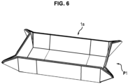
- the sides 11a, 12a, 13a, 14a are connected to the side parts in such a way that the side parts 15a, 16a, 17a, 18a can move from a first position P0 (see the figures 3 And 5 ) to a second position P1 (see Figure 6 ).
- the side parts are movable, the cover being able to be in a first position P0 or a second position P1.
- the side parts 15a, 16a, 17a, 18a are connected to the central part via first folding lines 110a, 120a, 130a, 140a constituting zones of fragility formed in the thickness of the cover 1a.
- the possibility of being able to raise the side parts makes it possible to move the cover from a first position P0 to a second position P1 and vice versa and allows the cover 1a to be used as a board game board.
- FIG. 6 illustrates the cover 1a seen from above with the side parts according to the second position P1.
- the cover 1a can serve as a game board and in particular as a dice throwing area.
- the side parts prevent dice thrown on the board from escaping.
- the cover 1a comprises eight holding parts 31a, 32a, 33a, 34a, 35a, 36a, 37a, 38a.
- Each of the holding parts is arranged between two side parts 15a, 16a, 17a, 18a.
- the holding parts 31a, 32a, 33a, 34a, 35a, 36a, 37a, 38a are arranged at each corner of the central part 10a.
- the holding parts 31a, 32a, 33a, 34a, 35a, 36a, 37a, 38a form two by two, between each lateral part 15a, 16a, 17a, 18a a square, each diagonal of which forms second folding lines 41a, 42a, 43a, 44a allowing two adjacent holding parts 31a, 32a, 33a, 34a, 35a, 36a, 37a, 38a to be folded over one another.
- two holding parts are pinched together towards the outside of the central part 10a.
- connecting means 51a, 52a, 53a, 54a, 55a, 56a, 57a, 58a are arranged on each holding part 31a, 32a, 33a, 34a, 35a, 36a, 37a, 38a.
- connecting means 51a, 52a, 53a, 54a, 55a, 56a, 57a, 58a can take several forms: magnets or textile strips comprising hooks such as Velcro TM or adhesives or press studs.
- magnets or textile strips comprising hooks such as Velcro TM or adhesives or press studs.
- two adjacent holding parts include complementary connecting means when necessary: magnet, Velcro TM , pressure button in particular.
- magnets are preferred, in fact, they are simple means which allow you to move effortlessly from the first position P0 to the second position P1 and vice versa. Indeed, once the corners are folded, they attract each other so that the cover can form the game board. Conversely, the corners are easily separated to form the cover.
- the cover 1a also comprises third folding lines 61a, 62a which each extend from an edge 151a, 161a, 171a, 181a of a side part to an edge of another side part, opposite, the third folding lines 61a, 62a allowing said U-shaped element to be folded to form a U-shaped cover for a board game box B as visible on the figure 2 (cover in a third position P2).
- the game element when used independently of the storage bin is advantageously a transformable game board which can be easily stored or transported.
- THE figures 7 and 8 illustrate a bin 2a for storing board game equipment.
- a tray 2a can be used alone or in combination with the cover 1a described above.
- the tray 2a has a parallelepiped shape and advantageously comprises a first compartment 21a and a second compartment 22a.
- Tray 2a is made of cardboard type material. Of course, other shapes are possible and is preferably made of material identical to the cover (see above).
- Each compartment 21a, 22a comprises a bottom 211a, 221a and a U-shaped rim 211b, 221b disposed above the bottom.
- the edges 211b, 221b can, for example, be glued to the bottom 211a, 221b.
- each locker has an open part above.
- Tray 2a has a first position illustrated on the figure 7 mainly allowing the storage of gaming equipment and allowing to receive the cover 1a to close the box B.
- the two compartments 21a, 22a are arranged one on top of the other when the bin 2a is in the storage position alone.
- the second locker 22a is movable relative to the first locker 21a to allow easy access to the second locker 21a below.
- the second compartment 22a can simply be placed above the first compartment 21a. A player can simply unfold the two lockers.
- the second compartment 22a is movably attached to the first compartment 21a. It can simply be fixed in a sliding manner.
- rail system for example, use of flexible materials, shaft mechanisms, axle mechanisms.
- these locker connection mechanisms are made invisible for aesthetic reasons.
- FIG 8 illustrates a storage bin 2a in which the second bin 22a is linked to the first bin 21a so as to allow access to the first bin 21a.
- the bin 2a can move from a first position to a second position which allows access to the gaming equipment stored in the box B.
- the first bin 21a is a lower bin while the second bin 22a East an upper locker arranged above the first locker 21a.
- the first locker 21a supports everything and rests in particular on a support such as a table to be used.
- the second compartment 22a is fixed to the first compartment 21a in a deployable manner by means of links connecting the first compartment to the second compartment in order to allow deployment of the second compartment 22a relative to the first compartment 21a.
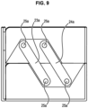
- two pairs of links 23a, 24a connect the first compartment 21a to the second compartment 22a: one pair on each side (only one side is illustrated on the Figure 9 .
- FIG. 10 illustrates a possible connection of the first compartment 21a and second compartment 22a by means of links 23a, 24a.
- the links 23a, 24a are fixed to the side walls of each of the two compartments 21a, 22a by means of pins 25a extending from orifices 26a located at the ends of the link towards complementary orifices 27a.
- each compartment 21a, 22a includes an imprint 28 adapted to the shape of the links 26a.
- intermediate plates 212a, 222a (comprising orifices 29a) are arranged on the links 26a and envelopes 213a, 223a cover the whole, the envelopes 213a, 223a include indentations 71a, 72a.
- the link mechanism 23a, 24a is hidden which gives the tray 2a aesthetics, that is to say an improved visual appearance.
- each locker 21a, 22a can be compartmentalized (as can be seen on the figure 8 ).
- each locker includes one or more compartment(s) 214a, 215a, 216a, 224a, 225a, 226a.
- each compartment 21a, 22a may include three compartments 214a, 215a, 216a, 224a, 225a, 226a of identical shapes and sizes.
- each compartment 214a, 215a, 216a, 224a, 225a, 226a comprises a cell 73a formed in the bottom 211a, 221a of each compartment 21a, 22a at the entrance to each compartment 214a, 215a, 216a, 224a, 225a, 226a.
- the cell 73a of each compartment 214a, 215a, 216a, 224a, 225a, 226a facilitates access to playing cards when the compartment 2a is deployed and serves as a playing card dispenser (see the figure 8 ).
- each compartment can be tilted so that when they contain cards these are kept immobile and are not likely to fall easily. As such, the bottom of each compartment is inclined towards its rear.
- the lower compartment 21a includes magnets 230a (the location is schematically presented - FIG 7 ) which, advantageously, are not visible for aesthetic reasons. These magnets are provided in sufficient number to allow the lid to be held in place, which includes magnets complementary to those provided on the first compartment 21a. Of course, magnets can be provided on the second compartment 22a.
- the tray 2a includes a part 217a that can be folded onto the compartments 21a, 22a ( FIG 8 ). In addition to being able to close the front parts of the lockers, this folding part 217a acts as a counterweight so that the storage bin 2a is held in position when the locker 22a is deployed in particular.
- THE figures 11 to 16 illustrate a game box B2 according to a second embodiment comprising a storage bin 11 according to a second embodiment and a cover 12 which can be transformed into a game board as described previously.
- Tray 11 includes a rectangular bottom 1110 common to two storage spaces.
- a first storage space is constituted by a compartment 111 comprising longitudinal walls 1111, 1112 perpendicular to the bottom 1110 and side walls 1113, 1114.
- the compartment 111 comprises a longitudinal intermediate wall 1115 parallel to one of the longitudinal walls 1111. This longitudinal intermediate wall 1115 delimits with the longitudinal wall 1111 a secondary storage space 1116 of small size.
- the compartment 111 presents a first so-called main storage space which allows most of the gaming equipment to be stored: for example boxes comprising playing cards.
- This so-called secondary storage space 1116 allows you to store additional material, a rule of the game or a particular accessory such as a particular card which requires to have its dedicated location.
- this secondary storage space 1116 is advantageously divided in two by a side wall 1117.
- the longitudinal walls 1112, 1111 include cutouts 1200 which facilitate access to the contents of the storage bin 11. These cutouts 1200 are rounded to facilitate access to the storage spaces but also to avoid having sharp edges which could damage the gaming equipment and in particular the cards.
- a second storage space is constituted by a box 112 and is attached to the compartment 111.
- This box 112 comprises four walls: two longitudinal 1122, 1123 and two lateral 1121, 1124 perpendicular to the bottom 1110.
- the longitudinal walls 1122, 1123 of the box 112 are respectively in the extension of the longitudinal walls 1111, 1112 of the compartment 111.
- the side walls 1121, 1124 of the housing 112 are parallel to the side walls 1113, 1114 of the compartment 111.
- One of the walls of the housing 111 also belongs to the compartment 112. On the Figure 13 , it is a side wall 1114.
- the housing 112 has locations 113, 114, 115 defined above the bottom: an upper location 115 accessible from above and one or more lower locations 113, 114 stacked under the upper assembly 115 (starting from top to bottom, the bottom being the bottom).
- the lower locations 113, 114 are separated by a shelf 116.
- this shelf 116 can be dispensed with to form a larger location.
- the housing 112 preferably comprises three locations: an upper location 115 and two lower locations 113, 114.
- the lower locations are advantageously accessible thanks to a longitudinal wall 1123 which is movable relative to the bottom 1110.
- the movable wall 1123 allows access to locations via a front face of the storage bin 11.
- this wall 1123 is mounted movable relative to a side 1125 of the bottom 1110 of the storage bin 11 at the level of the housing 12 for be actuated towards a low position such that it can be parallel to the bottom 1110. In this way it is easy to access the locations 113, 114.
- the housing 112 comprises means for connecting the movable wall 1123 in order to maintain the movable wall 1123 in the high position.
- the high position of the movable wall is a high position, that is to say perpendicular to the bottom 1110 of the storage bin 11 at the level of the housing 12. In this way, the movable wall 1123 can close the locations of the housing 112.
- These connecting means can also form means for returning the movable wall 1123 so that it returns to the high position when it is raised.
- connecting means can take several forms: magnets or textile strips including hooks such as Velcro TM or adhesives or press studs.
- connection means also form the return means, the latter being constituted by magnetized parts 117, 118 arranged on a longitudinal wall 1151 of the upper location 115 and by magnetized parts 117', 118' complementary to those arranged on the upper location 115.
- the magnetic parts of the movable wall 1123 and those of the upper location attract each other.
- they attract each other to press the movable wall 1123 against the housing 112. This attraction allows that when the movable wall 1123 begins to be raised it finds itself easily pressed against the housing 112. Its actuation is therefore easy, closing of the housing 112 is therefore easy.
- the magnetized parts 117, 118, 117', 118' are shown schematically by circles in the figures but are invisible in practice. In addition, other shapes for these magnetic parts are possible.
- the upper location 115 has a bottom 1152 and two longitudinal walls 1151, 1153, one of which includes the magnetic parts 117, 118.
- a cutout 119 is also provided on the wall 1151 comprising the magnets 117, 118 in order to create a space between the movable wall 1123 and the upper location 115 so as to be able to actuate this movable wall 1123.
- the connection and possibly return means are such that when the movable wall is in position high, it is firmly held to correctly close the lower slots.
- the fact of preferring magnetic parts for the connecting means is that it also forms means for returning the movable wall 1123 when it is close to the magnetized part of the upper location.
- the upper location 115 has a closed area which can for example serve as a dice throwing area during the game.
- lower locations here two lower locations of identical sizes. These locations are advantageously intended to receive drawers intended to contain gaming equipment such as cards. If the shelf 116 is not present, the drawers can be stacked on top of each other.
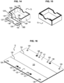
- a drawer 13 with a movable wall (see figures 14 and 15 ) comprises a rectangular bottom 130, two longitudinal walls 131, 132 and two side walls 133, 134 perpendicular to the bottom.
- a longitudinal wall 131 is mounted movable relative to one side 135 of the bottom to be actuated between a high position such that the four walls close the four sides and a low position such that one side 135 is accessible. This is the front of the drawer.
- the drawer 13 further comprises connecting means also advantageously forming means for returning the movable wall 131 to return it to the high position when it is raised.
- connection and return means consist of intermediate walls 1360, 1370 extending from the side 135 accessible by the movable wall 131, the intermediate walls 1360, 1370 being arranged at each end of the accessible side 135, and are perpendicular to both at the bottom 130 and at the longitudinal walls 131, 132.
- the movable wall 131 is in contact with the intermediate walls 1360, 1370 when in the high position.
- the means of connection and return of the movable wall are advantageously constituted by magnetized parts 1361, 1371 arranged on the intermediate walls and by complementary magnetized parts 1361', 1371' arranged on the movable wall 131. In this way the magnetized parts of the moving wall and those on the intermediate walls attract each other.
- the movable wall 131 Preferably, they attract each other to press the movable wall 131 against the intermediate walls.
- This attraction means that when the movable wall begins to be raised, it easily finds itself pressed against the intermediate walls.
- the magnetic parts which attract each other are opposite each other when the movable wall 131 is in the high position and pressed against the intermediate walls.
- the magnetic parts are represented schematically by circles on the Figure 14 but are invisible in practice. In addition, other shapes for these magnetic parts are possible.
- circular magnets are positioned on each intermediate wall as well as on the movable wall.
- these connecting means can take several forms: magnets or textile strips comprising hooks such as Velcro TM or adhesives or press studs.
- the fact of providing magnets makes it easier to manipulate the movable wall of the drawer. Indeed, by simply raising the movable wall as soon as it is close to the intermediate walls comprising the magnets, it is attracted by the latter which facilitates its handling and therefore the closing of the drawer 13.
- each box when the four walls of the drawer 13 are in the high position, each box has the shape of a tray, the movable wall being against the intermediate walls (see the Figure 15 ).
- the bottom 130 of the drawer 13 comprises a step 1300 extending from the accessible side 135 so that the bottom 130 includes a positive difference in height from the accessible side.
- the movable wall 131 comprises a central rounded cutout 136 (see the Figure 14 ).
- This movable wall 131 also serves as a tab to pull the drawer 13 from its location in the storage bin 11 if necessary.
- the storage bin 11 can advantageously be closed by a cover 12 which comprises a rectangular central part 120 from which rectangular side parts 121, 122 extend.
- a cover 12 can be similar to that described previously.
- the side parts 121, 122 are connected to the central part 120 by folding lines 123, 124 which allow the cover 12 to be in a flat position (see the figures 13 And 16 ) or U-shaped (see figures 11 and 12 ), the walls lateral parts 121, 122 being perpendicular to the central part 120 and are therefore raised relative to this central part 120 when the cover 12 forms a U.
- the cover 12 In flat position (see figures 13 And 16 ), the cover 12 is placed under the storage bin 11 (see the figure 13 the central part 120 being of identical size to the bottom 1110 of the storage bin 11. It is understood that the fact of being able to place it under the storage bin 11 prevents it from being too bulky when the game is taking place and that It is necessary to access the game elements stored in storage bin 11.
- the side parts 121, 122 of the cover 12 have dimensions smaller than the height of the walls of the storage bin 11.
- the cover in the U-shaped position makes it possible to close the storage bin 11.
- Holding means 125, 126, 127 , 128 are further arranged on the side parts 121, 122 of the cover 12 so that it is firmly attached to the storage bin 11 when it closes the storage bin or even when it is under the storage bin 11.
- These means of support can take several forms.
- the holding means are constituted by magnetized parts 125, 126 arranged on the side walls 121, 122 which are intended to be pressed against the longitudinal walls of the storage bin 11: here two magnetized parts per side wall 121, 122.
- These holding means also include magnetic parts 125', 126' complementary to those arranged on the side walls of the cover but arranged on the longitudinal walls of the storage bin 11 (see the figure 13 ).
- On the figure 13 we can only clearly see those arranged on the longitudinal wall 1112 of the storage tank 11 but the other wall includes the same complementary magnetic parts.
- four magnetic parts are present.
- holding means can take several forms: magnets or textile strips including hooks such as Velcro TM or adhesives or press studs. The case with magnetic parts is described below, but this also applies to other alternatives for holding means.
- the holding means also include buttons (knob in English) intended to be housed in complementary female parts, the buttons constituting the male part.
- the buttons 127, 128 are advantageously arranged between the magnetic parts of the side walls 121, 122 of the cover 12 on the face intended to be placed against the storage bin 11.
- the female parts 127' are positioned on the longitudinal walls 1111, 1112 of the storage bin 11 in which the buttons must fit.
- Combining the magnetic parts with the buttons ensures that the cover is firmly attached to the storage bin 11, in addition it helps guide the user in positioning the cover 12 on the storage bin 11.
- tank 11 is closed and cannot let anything escape.
- the storage bin 11 and the cover 12 thus constitute a game box B2 which allows the game elements to be stored firmly and securely. The latter are in their place and correctly maintained.
- the cover 12 is completely separable from the storage bin 11. To do this, it is sufficient to move the side walls 121, 122 of the cover of the storage bin 11 using the folding lines and to lift the cover.
- the fact of preferring magnetic parts to other alternatives makes it possible to benefit from the attraction between the different magnetic parts which facilitate the positioning of the cover 12 on the storage bin 11. Also, the cover does not make sense for be positioned on the storage bin. You just have to ensure that the side walls with the buttons of the cover 12 are positioned to be pressed against the longitudinal walls of the storage bin 11.
- the holding means are simply constituted by the buttons and therefore without magnetic parts.
- connection means connection means with the recall means
- recall means recall means
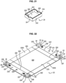
- THE figures 17 to 23 illustrate in particular a game box B3 according to a third embodiment comprising a storage bin 21 and a cover 22.
- the storage bin 21 for this box 2 is advantageously larger than the storage bin 11 of the box B2 according to the second embodiment.
- Tray 21 includes a rectangular bottom 2110 common to two storage spaces (see Figure 17 ): a first storage space composed of a compartment 211 and a second storage space is constituted by a box 212. The two storage spaces are attached to each other.
- the first storage space comprises side walls 2111, 2112 perpendicular to the bottom 2110 and longitudinal walls 2113, 2114.
- a removable wall 300 makes it possible to adjust the storage space constituted by the compartment 211. Grooves 301 are formed inside the compartment on the internal faces of the longitudinal walls. The removable wall 300 can be placed in these grooves depending on the spaces desired for the compartment 211. The removable wall 300 when not in use can be stored in various places: under the storage bin or in the compartments when the Space permits, even above the cards.
- the side walls 2111, 2112 include cutouts 2200 which facilitate access to the contents of the storage bin. These 2200 cutouts are rounded to facilitate access to storage spaces but also to avoid having sharp edges which could damage the gaming equipment and in particular the cards.
- the second storage space comprises four walls: two side walls 2123, 2124 and two longitudinal walls 2121, 2122 connected to the bottom 2110: one of the walls is common with a wall of the compartment 211.
- the box 212 includes locations 213, 214, 215: an upper location 215 accessible from above and lower locations under the upper assembly (starting from top to bottom, the bottom being the bottom).
- a shelf 216 can be provided to delimit the lower locations 213, 214. This shelf 216 can be dispensed with to form a larger location.
- the housing 212 has two movable side walls 2123, 2124 which allow access to the locations lower by two opposite faces of the housing 212.
- This is advantageous insofar as it is possible to store drawers 13 with movable walls already described in relation to the figures 14 and 15 concerning the box according to the second embodiment.
- the movable walls 2123, 2124 according to this third embodiment are identical to those of the box B2 according to the second embodiment: connecting means preferably forming return means constituted by magnetized parts 217, 218 arranged on a wall 2151 , 2152 of the upper location 215, the movable walls 2123, 2124 comprising complementary magnetic parts 217', 218'.
- Cutouts 219 are provided on the wall 2151, 2152 comprising the connecting means 217, 218 in order to create a space between each movable wall 2123, 2124 and the upper location so as to be able to operate the movable wall 2123.
- the connecting means alone can take several forms: magnets or textile strips including hooks such as Velcro TM or adhesives or snap buttons.
- the connecting means 217, 218 are magnetized, they also form return means to bring back the movable wall 2123 as soon as it is actuated.
- the upper location has a closed Z zone which can serve as a dice throwing area during the game, as a storage area for any materials necessary for the game: notebook, pen, etc.
- the simple 24 drawer(s) has(have) a rectangular bottom 240 and rectangular walls 241, 242, 243, 244 at the bottom 240. Cutouts 245 are provided on opposite walls which allow the simple drawer 24 to be grasped when it is in the location. The fact of providing opposite cutouts makes it possible not to impose a direction of storage of the simple drawer in a location of the box 212. Of course, a single notch can be provided but in this case the storage of the simple drawer will only be facilitated in one direction.
- Such simple drawers 24 can be stored in the locations of the box housing according to the first embodiment.
- the storage bin 21 can advantageously be closed by a cover 22 of the same type as that of the first embodiment.
- the cover is in position such that it forms a cover for box 2, on the Figure 19 , it is positioned under the storage bin 21 for reasons of space.
- the cover here is again of the same type as that described previously.
- the cover 22 comprises side parts 221, 222 connected to a central part 220 by folding lines 223, 224 which allow the cover 22 to be in a flat position (see the Figure 22 ) or U-shaped (see Figure 17 ), the side walls 221, 222 then being perpendicular to the central part 220 and are therefore raised relative to this central part 220 when the cover forms a U.
- the cover 22 In the flat position, the cover 22 is placed under the storage bin 21.
- the cover in the U-shaped position makes it possible to close the storage bin 21.
- Holding means are also arranged on the lateral parts 221, 222 of the cover 22 so that it is firmly attached to the storage bin 21 when it closes the storage bin.
- These holding means are advantageously constituted by magnetic parts 225, 226 making it possible to connect the cover 22 to the storage container 21, the walls of the storage container 21 comprising complementary magnetic parts 226' which attract those of the cover 22.
- complementary magnetic parts are also present on the wall 2112 but not visible in these figures.
- These magnetic parts are advantageously coupled to buttons intended to be housed in the complementary female parts, the buttons constituting the male part.
- the buttons 227, 228 are advantageously arranged on the side parts 221, 222 of the cover 22.
- buttons are adapted to be housed in female parts 227' arranged on the side walls of the storage bin 21.
- the cover 22 is here again completely separable from the storage bin 21. To do this, simply to move aside the side walls 221, 222 of the cover of the storage bin 21 using the folding lines and to lift the cover.
- the cover 22 can be transformed into a game board, that is to say it can serve as an area in which the game takes place.
- the lateral parts 221, 222 include secondary folding lines 224' which form lateral portions 231, 232 of each lateral part 221, 222 and which also form other lateral portions 2230 at the level of the central part 220.
- the cover 22 comprises eight holding parts 31, 32, 33, 34, 35, 36, 37, 38. Each of the holding parts is arranged between two side portions. In particular, the holding parts 31, 32, 33, 34, 35, 36, 37, 38 are arranged at each corner of the central part 220.
- the holding parts 31, 32, 33, 34, 35, 36, 37, 38 form two by two, between each lateral portion a square, each diagonal of which forms folding lines 41, 42, 43, 44 allowing the folding of the two adjacent holding parts one on top of the other.
- two holding parts are pinched together towards the outside of the central part 220.
- connecting means are arranged on each holding part.
- holding means can take several forms: magnets or textile strips including hooks such as Velcro TM or adhesives or snap buttons.
- magnets or textile strips including hooks such as Velcro TM or adhesives or snap buttons.
- two adjacent holding parts include complementary holding means when necessary: magnet, Velcro TM , pressure button in particular.
- magnets are preferred, in fact, they are simple means which make it possible to form the game board. In fact, once the corners are folded they attract each other so that the cover 22 can form the game board. Conversely, the corners are easily separated to form the cover.
- the cover 22 which can be transformed into a game board can also be used in combination with the storage bin 11 according to the second embodiment by adapting its size.
- the box 1, 2 is advantageously based on cardboard having a thickness of between 2 and 6 mm.
- the cardboard is advantageously covered with a decorative material.
- the box is made up of an internal material and an external material around a base material such as cardboard, PP (polypropylene) or any other plastic.
- PP polypropylene
- the outer material is usually PU leatherette, but it can also be any type of fabric.
- it is PU imitation leather on one side and microfiber fabric on the other.
- the box B3 includes in particular longer drawers for storing accessories: these are simple drawers which have fixed walls and which are located at the rear of the box B3 (see the Figure 19 ).
- This B3 box also includes “shorter” drawers for card storage which have movable walls and are located at the front of the B3 box (see the Figure 19 ).
- the single drawers are positioned at the rear of the box while the drawers with movable walls are positioned at the front.
Landscapes
- Engineering & Computer Science (AREA)
- Multimedia (AREA)
- Mechanical Engineering (AREA)
- Slot Machines And Peripheral Devices (AREA)
- Packaging Of Annular Or Rod-Shaped Articles, Wearing Apparel, Cassettes, Or The Like (AREA)
- Purses, Travelling Bags, Baskets, Or Suitcases (AREA)
- Pinball Game Machines (AREA)
Claims (15)
- Spielelement (1a), vorzugsweise eines Gesellschaftsspielkastens (B1, B2, B3), umfassend:- einen zentralen Abschnitt (10a), der vier Seiten (11a, 12a, 13a, 14a) umfasst;- Seitenabschnitte (15a, 16a, 17a, 18a), wobei jeder mit einer Seite (11a, 12a, 13a, 14a) des zentralen Abschnitts (10) derart verbunden ist, dass die Seitenabschnitte (15a, 16a, 17a, 18a) aus einer ersten Position (P0) in eine zweite Position (P1) wechseln können:- wobei die erste Position (P0) eine Position ist, in der das Element (1a) flach ist;- wobei die zweite Position (P1) eine Position ist, in der die Seitenabschnitte im Verhältnis zum zentralen Abschnitt (10a) aufgerichtet sind, so dass das Element (1a) ein Spielbrett für ein Gesellschaftsspiel bildet,dadurch gekennzeichnet, dass das Spielelement (1a) acht Halteabschnitte umfasst, wobei jeder Halteabschnitt zwischen zwei Seitenabschnitten angeordnet ist, wobei die Halteabschnitte mit einem benachbarten Seitenabschnitt (15a, 16a, 17a, 18a) und einem anderen Halteabschnitt derart verbunden sind, dass die Seitenabschnitte (15a, 16a, 17a, 18a) in aufgerichteter Position gehalten werden können, wenn das Element ein Spielbrett bildet.
- Element (1a) nach Anspruch 1, wobei die Seitenabschnitte ferner derart beweglich sind, dass das Element in einer dritten Position (P2) ist, um einen Deckel eines Gesellschaftsspielkastens zu bilden.
- Element (1a) nach einem der Ansprüche 1 bis 2, wobei die Halteabschnitte Verbindungsmittel umfassen, die dazu ausgelegt sind, benachbarte Halteabschnitte paarweise zu verbinden, wenn das Element (1a) ein Spielbrett bildet.
- Element (1a) nach Anspruch 3, wobei die Verbindungsmittel von Magneten oder Textilstreifen gebildet sind, die Haken wie Velcro™ oder Haftmittel oder Druckknöpfe umfassen.
- Element (1a) nach einem der vorangehenden Ansprüche, wobei die Seitenabschnitte mit den Seiten des zentralen Abschnitts (10a) über erste Faltlinien (110a, 120a, 130a, 140a) verbunden sind.
- Element (1a) nach einem der Ansprüche 1 bis 5, wobei die Halteabschnitte über zweite Faltlinien (41a, 42a, 43a, 44a) paarweise verbunden sind.
- Element (1a) nach einem der vorangehenden Ansprüche, umfassend dritte Faltlinien, die sich jeweils von einem Rand eines Seitenabschnitts zu einem Rand eines anderen Seitenabschnitts gegenüber erstrecken, wobei die Faltlinien gestatten, das Element in U-Form zu falten, um einen Deckel in U-Form für einen Gesellschaftsspielkasten zu bilden.
- Gesellschaftsspielkasten, umfassend:- einen Behälter (2a), der geeignet ist, Gesellschaftsspielmaterial zu enthalten;- ein Element (1a) nach einem der vorangehenden Ansprüche, das einen Deckel für den Gesellschaftsspielbehälter oder das Gesellschaftsspielspielbrett bildet.
- Gesellschaftsspielkasten nach Anspruch 8, wobei der Behälter (2a) ein erstes Fach (21a) und ein zweites Fach (22a) umfasst, wobei das zweite Fach (22a) über dem ersten Fach (21a) angeordnet ist und mit dem ersten Fach (21a) derart zusammengebaut ist, dass es im Verhältnis zum ersten Fach (21a) beweglich ist, um Zugriff auf das erste Fach zu haben.
- Spielekasten nach einem der Ansprüche 8 bis 9, wobei jedes Fach (21a, 22a) Abteile umfasst, die zur Aufbewahrung von Gesellschaftsspielmaterial geeignet sind.
- Spielekasten nach einem der Ansprüche 8 bis 10, umfassend ein Element (1a) nach Anspruch 5, das für den Behälter (2a) einen Deckel in U-Form bildet.
- Spielekasten nach einem der Ansprüche 8 bis 11, umfassend ein Gehäuse (112, 212), das einen von zwei Seitenwänden (2121, 2122) begrenzten Stauraum bildet, wobei der Stauraum mindestens eine Stelle (113, 114, 213, 214) aufweist, die einen Schubkasten (13) aufnimmt, wobei der Schubkasten (13) umfassteinen rechteckigen Boden (130);drei zum Boden senkrechte Wände (132, 133, 134), die sich jeweils ab drei Seiten des Bodens erheben;eine vierte Wand (131), die im Verhältnis zu einer vierten Seite beweglich angebracht ist, um zwischen einer hohen Position, in der die vier Wände die Seiten des Bodens schließen, und einer niedrigen Position, in der eine Seite zugänglich ist, betätigt zu werden;Rückstellmittel (1360, 1361, 1361', 1370, 1371, 1371') der beweglichen vierten Wand (131), um sie in die hohe Position zurückzuführen, wenn sie im Begriff ist, angehoben zu werden.
- Spielekasten nach Anspruch 12, wobei der Schubkasten zwei Zwischenwände umfasst, die sich ab der zugänglichen Seite erstrecken, wenn die bewegliche Wand in niedriger Position ist, wobei die Wände an jedem Ende der zugänglichen Seite angeordnet sind, wobei die bewegliche Wand mit den Zwischenwänden im Kontakt ist, wenn sie in hoher Position ist.
- Spielekasten nach einem der Ansprüche 12 bis 13, wobei die Rückstellmittel der beweglichen Wand des Schubkastens aus komplementären magnetisierten Abschnitten bestehen, die auf den Zwischenwänden und der beweglichen Wand angeordnet sind, so dass die bewegliche Wand in ihre hohe Position angezogen wird, wenn sie angehoben wird.
- Kasten nach einem der Ansprüche 11 bis 14, wobei der Boden des Schubkastens eine Stufe umfasst, die sich ab dem Rand der zugänglichen Seite derart erstreckt, dass der Boden eine positive Unebenheit ab dem Rand der zugänglichen Seite umfasst.
Applications Claiming Priority (3)
| Application Number | Priority Date | Filing Date | Title |
|---|---|---|---|
| FR2003844A FR3109322B1 (fr) | 2020-04-16 | 2020-04-16 | Elément de boite de jeu formant couvercle d’une boite de jeu ou plateau de jeu, boite de jeu associée |
| FR2101653A FR3120061B1 (fr) | 2021-02-19 | 2021-02-19 | Casier à paroi mobile d’une boite de jeu et boite de jeu associée |
| PCT/EP2021/059938 WO2021209610A1 (fr) | 2020-04-16 | 2021-04-16 | Elément de boite de jeu formant couvercle d'une boite de jeu ou plateau de jeu, boite de jeu associée |
Publications (2)
| Publication Number | Publication Date |
|---|---|
| EP4135863A1 EP4135863A1 (de) | 2023-02-22 |
| EP4135863B1 true EP4135863B1 (de) | 2024-05-29 |
Family
ID=75478066
Family Applications (1)
| Application Number | Title | Priority Date | Filing Date |
|---|---|---|---|
| EP21718140.3A Active EP4135863B1 (de) | 2020-04-16 | 2021-04-16 | Spielkastenelement, das den deckel eines spielkastens oder spielbretts bildet, dazugehöriger spielkasten |
Country Status (4)
| Country | Link |
|---|---|
| US (1) | US12599834B2 (de) |
| EP (1) | EP4135863B1 (de) |
| CN (1) | CN115397527B (de) |
| WO (1) | WO2021209610A1 (de) |
Families Citing this family (12)
| Publication number | Priority date | Publication date | Assignee | Title |
|---|---|---|---|---|
| US12351370B2 (en) | 2018-08-07 | 2025-07-08 | Graphic Packaging International, Llc | Container with liner |
| KR102686303B1 (ko) | 2018-08-07 | 2024-07-17 | 그래픽 팩키징 인터내셔날, 엘엘씨 | 라이너를 구비한 용기 |
| USD1080212S1 (en) * | 2021-01-26 | 2025-06-24 | Gamegenic Gmbh | Card storage box |
| USD1080207S1 (en) * | 2021-01-26 | 2025-06-24 | Gamegenic Gmbh | Card storage box |
| USD1090249S1 (en) * | 2021-02-19 | 2025-08-26 | Kimoto Co., Ltd. | Packaging box |
| JP1706460S (ja) * | 2021-04-27 | 2022-02-01 | 包装用箱 | |
| US12458869B2 (en) * | 2022-04-08 | 2025-11-04 | Heavy Play LLC | Gameplay area system |
| AU2023259520A1 (en) * | 2022-04-29 | 2024-10-24 | Graphic Packaging International, Llc | Container with liner. |
| USD1098835S1 (en) | 2023-03-13 | 2025-10-21 | Graphic Packaging International, Llc | Tray system |
| USD1040924S1 (en) | 2023-10-03 | 2024-09-03 | Gamegenic Gmbh | Card storage box |
| US12403386B2 (en) * | 2025-01-14 | 2025-09-02 | Shenzhen Youlequ Trading Co., Ltd. | Magnetic type card box assembly |
| USD1082306S1 (en) * | 2025-04-01 | 2025-07-08 | Nanning Weimao Trading Co., Ltd. | Card storage box |
Citations (3)
| Publication number | Priority date | Publication date | Assignee | Title |
|---|---|---|---|---|
| EP2545968A1 (de) * | 2011-07-12 | 2013-01-16 | Nova Carta Beheer B.V. | Verpacken von Puzzles oder Brettspielen und Anordnung einer derartigen Verpackung und Objekte, die Bestandteil eines Puzzles oder eines Brettspiels sind |
| DE202015103334U1 (de) * | 2015-06-25 | 2015-07-08 | Sergiu Vrabie | In einen Rahmen umwandelbare Verpackung |
| CN106730793B (zh) * | 2017-01-12 | 2019-10-01 | 杭州耀晗光伏技术有限公司 | 新型太阳能公用棋盘 |
Family Cites Families (25)
| Publication number | Priority date | Publication date | Assignee | Title |
|---|---|---|---|---|
| GB207323A (en) * | 1922-10-06 | 1923-11-29 | Isaiah Hughes | Improvements in and relating to chess and draughts boards and the like |
| FR1111669A (fr) * | 1954-09-21 | 1956-03-02 | Formisyn | Nouvelle boîte |
| US5478085A (en) | 1995-02-14 | 1995-12-26 | Canner; Bonnie | Magnetic domino set |
| FR2734735B1 (fr) * | 1995-05-31 | 1997-08-08 | Monnet Gilles | Ensemble destine a recevoir les pieces de jeu d'un jeu de societe |
| AUPO947597A0 (en) * | 1997-09-29 | 1997-10-23 | Johannsen, Peter Kurt | Improved foldable box |
| US6203017B1 (en) * | 1999-08-02 | 2001-03-20 | Mattel, Inc. | Folding board game having pop-up features |
| US20040007814A1 (en) * | 2002-07-11 | 2004-01-15 | Senart Joseph C. | Integral folding game board and box |
| US20040207298A1 (en) | 2003-04-17 | 2004-10-21 | Rodon Frank C. | Work storage unit |
| DE202004005235U1 (de) * | 2004-04-02 | 2004-06-17 | Helmut Angles Druck & Verlag E.K. | Würfelförmige Verpackung |
| US7597209B2 (en) * | 2005-01-28 | 2009-10-06 | International Holdings, Llc | Multipurpose storage device and method |
| US20060208062A1 (en) | 2005-03-16 | 2006-09-21 | Osborn Warren R | Injection molded gift case for debit, credit and smart cards |
| MXPA06007997A (es) * | 2005-07-13 | 2007-03-30 | Meadwestvaco Packaging Systems Llc | Sistema y metodo para proporcionar un juego portatil. |
| GB0711622D0 (en) * | 2007-06-15 | 2007-07-25 | Book Link Uk Ltd | Blank for forming a box for a book |
| FI120139B (fi) | 2007-08-14 | 2009-07-15 | Pasi Leskinen | Laite pientavaroiden yhteydessä |
| US20090058003A1 (en) * | 2007-09-04 | 2009-03-05 | Nouhan Jr Harry P | Combination delivery box and board game |
| GB2470055A (en) * | 2009-05-07 | 2010-11-10 | Lindi Jean Lawrenson | A system of nested storage boxes |
| US9289695B2 (en) * | 2011-10-15 | 2016-03-22 | Really Brothers, Llc | Folding toy figurine and method for making same |
| JP6157074B2 (ja) | 2012-08-05 | 2017-07-05 | エンゼルプレイングカード株式会社 | シャッフルプレイングカードの包装箱 |
| DE202013012311U1 (de) | 2013-11-14 | 2016-03-02 | Ds Smith Packaging Deutschland Stiftung & Co. Kg | Zuschnitt und hieraus hergestellte Verpackung |
| ES2687271T3 (es) | 2014-06-27 | 2018-10-24 | Philip Morris Products S.A. | Recipiente que tiene una pared móvil y método para la producción del mismo |
| US20180339837A1 (en) * | 2017-05-23 | 2018-11-29 | Alan J. Fitt | Collapsible Storage Apparatus |
| GB2565311A (en) * | 2017-08-09 | 2019-02-13 | Tri Pack Plastics Ltd | Box |
| CN208097404U (zh) * | 2018-04-19 | 2018-11-16 | 深圳信息职业技术学院 | 一种正方体玩具盒子 |
| US10660734B1 (en) * | 2018-12-21 | 2020-05-26 | SmileDirectClub LLC | Dental aligner packaging |
| KR102167656B1 (ko) | 2019-12-04 | 2020-10-19 | 박찬웅 | 치과기공용 조각도 세트 |
-
2021
- 2021-04-16 CN CN202180028712.2A patent/CN115397527B/zh active Active
- 2021-04-16 WO PCT/EP2021/059938 patent/WO2021209610A1/fr not_active Ceased
- 2021-04-16 EP EP21718140.3A patent/EP4135863B1/de active Active
- 2021-04-16 US US17/918,942 patent/US12599834B2/en active Active
Patent Citations (3)
| Publication number | Priority date | Publication date | Assignee | Title |
|---|---|---|---|---|
| EP2545968A1 (de) * | 2011-07-12 | 2013-01-16 | Nova Carta Beheer B.V. | Verpacken von Puzzles oder Brettspielen und Anordnung einer derartigen Verpackung und Objekte, die Bestandteil eines Puzzles oder eines Brettspiels sind |
| DE202015103334U1 (de) * | 2015-06-25 | 2015-07-08 | Sergiu Vrabie | In einen Rahmen umwandelbare Verpackung |
| CN106730793B (zh) * | 2017-01-12 | 2019-10-01 | 杭州耀晗光伏技术有限公司 | 新型太阳能公用棋盘 |
Also Published As
| Publication number | Publication date |
|---|---|
| CN115397527A (zh) | 2022-11-25 |
| US20230277918A1 (en) | 2023-09-07 |
| WO2021209610A1 (fr) | 2021-10-21 |
| EP4135863A1 (de) | 2023-02-22 |
| CN115397527B (zh) | 2026-04-17 |
| US12599834B2 (en) | 2026-04-14 |
Similar Documents
| Publication | Publication Date | Title |
|---|---|---|
| EP4135863B1 (de) | Spielkastenelement, das den deckel eines spielkastens oder spielbretts bildet, dazugehöriger spielkasten | |
| EP4294541B1 (de) | Spielboxfach mit beweglicher wand und zugehörige spielbox | |
| US7552821B1 (en) | Puzzle storage and service case | |
| FR2515015A1 (fr) | Meuble transformable formant chevalet | |
| EP0227123A2 (de) | Kästchen für ein Brettspiel | |
| CA2764770A1 (fr) | Ensemble de malles de transport empilables | |
| FR2648052A1 (fr) | Plateau de jeu de table formant un coffret en forme de livre | |
| FR3008386A1 (fr) | Boite pour le conditionnement, le transport et la presentation de denrees alimentaires | |
| FR3109322A1 (fr) | Elément de boite de jeu formant couvercle d’une boite de jeu ou plateau de jeu, boite de jeu associée | |
| EP0031314A1 (de) | Einordnungselement mit mehreren Fächern | |
| KR102892537B1 (ko) | 독서대로 사용이 가능한 퍼즐게임 다용도 테이블 | |
| FR2978336A1 (fr) | Meuble contenant un tiroir a double extension coaxiale | |
| EP1109472B1 (de) | Rollmöbelvorrichtung für die verwaltung eines raumes | |
| EP0819394A1 (de) | Büro- oder Pultartiger Einrichtungsgegenstand mit in der Arbeitsfläche integriertem Schreibblock | |
| JP3122576U (ja) | 収納部付き本 | |
| FR2755103A1 (fr) | Caisse-palette comprenant des plots et au moins un entourage | |
| EP3072561B1 (de) | Versenkbarer tischkicker | |
| FR3138907A1 (fr) | Emballage pliable, notamment pour former un ecrin | |
| FR2718050A1 (fr) | Jeu de société à tableaux variables sans déplacement de pièces présentant des cases actives à deux aspects. | |
| BE1005321A4 (fr) | Coffret pour au moins un disque a haute densite d'information. | |
| CH719976B1 (fr) | Emballage pliable et dispositif destiné à loger un objet, par exemple une montre | |
| BE1003839A5 (fr) | Coffret pour au moins un disque a haute densite d'information. | |
| FR2899074A1 (fr) | Valise pour le transport et le rangement d'une plaque de plomb pour le jeu de palet | |
| WO1992012771A1 (fr) | Support de jeu avec elements mobiles integres | |
| FR2816183A1 (fr) | Ensemble de composants independants et separables pour constituer des dispositifs de mobiliers roulants |
Legal Events
| Date | Code | Title | Description |
|---|---|---|---|
| STAA | Information on the status of an ep patent application or granted ep patent |
Free format text: STATUS: UNKNOWN |
|
| STAA | Information on the status of an ep patent application or granted ep patent |
Free format text: STATUS: THE INTERNATIONAL PUBLICATION HAS BEEN MADE |
|
| PUAI | Public reference made under article 153(3) epc to a published international application that has entered the european phase |
Free format text: ORIGINAL CODE: 0009012 |
|
| STAA | Information on the status of an ep patent application or granted ep patent |
Free format text: STATUS: REQUEST FOR EXAMINATION WAS MADE |
|
| 17P | Request for examination filed |
Effective date: 20220909 |
|
| AK | Designated contracting states |
Kind code of ref document: A1 Designated state(s): AL AT BE BG CH CY CZ DE DK EE ES FI FR GB GR HR HU IE IS IT LI LT LU LV MC MK MT NL NO PL PT RO RS SE SI SK SM TR |
|
| DAV | Request for validation of the european patent (deleted) | ||
| DAX | Request for extension of the european patent (deleted) | ||
| GRAP | Despatch of communication of intention to grant a patent |
Free format text: ORIGINAL CODE: EPIDOSNIGR1 |
|
| STAA | Information on the status of an ep patent application or granted ep patent |
Free format text: STATUS: GRANT OF PATENT IS INTENDED |
|
| RIC1 | Information provided on ipc code assigned before grant |
Ipc: B65D 81/36 20060101ALI20231206BHEP Ipc: B65D 5/32 20060101ALI20231206BHEP Ipc: A63F 3/00 20060101AFI20231206BHEP |
|
| INTG | Intention to grant announced |
Effective date: 20231220 |
|
| GRAS | Grant fee paid |
Free format text: ORIGINAL CODE: EPIDOSNIGR3 |
|
| GRAA | (expected) grant |
Free format text: ORIGINAL CODE: 0009210 |
|
| STAA | Information on the status of an ep patent application or granted ep patent |
Free format text: STATUS: THE PATENT HAS BEEN GRANTED |
|
| AK | Designated contracting states |
Kind code of ref document: B1 Designated state(s): AL AT BE BG CH CY CZ DE DK EE ES FI FR GB GR HR HU IE IS IT LI LT LU LV MC MK MT NL NO PL PT RO RS SE SI SK SM TR |
|
| REG | Reference to a national code |
Ref country code: CH Ref legal event code: EP |
|
| REG | Reference to a national code |
Ref country code: IE Ref legal event code: FG4D Free format text: LANGUAGE OF EP DOCUMENT: FRENCH |
|
| REG | Reference to a national code |
Ref country code: DE Ref legal event code: R096 Ref document number: 602021013835 Country of ref document: DE |
|
| REG | Reference to a national code |
Ref country code: LT Ref legal event code: MG9D |
|
| REG | Reference to a national code |
Ref country code: NL Ref legal event code: MP Effective date: 20240529 |
|
| PG25 | Lapsed in a contracting state [announced via postgrant information from national office to epo] |
Ref country code: IS Free format text: LAPSE BECAUSE OF FAILURE TO SUBMIT A TRANSLATION OF THE DESCRIPTION OR TO PAY THE FEE WITHIN THE PRESCRIBED TIME-LIMIT Effective date: 20240929 |
|
| PG25 | Lapsed in a contracting state [announced via postgrant information from national office to epo] |
Ref country code: BG Free format text: LAPSE BECAUSE OF FAILURE TO SUBMIT A TRANSLATION OF THE DESCRIPTION OR TO PAY THE FEE WITHIN THE PRESCRIBED TIME-LIMIT Effective date: 20240529 |
|
| PG25 | Lapsed in a contracting state [announced via postgrant information from national office to epo] |
Ref country code: HR Free format text: LAPSE BECAUSE OF FAILURE TO SUBMIT A TRANSLATION OF THE DESCRIPTION OR TO PAY THE FEE WITHIN THE PRESCRIBED TIME-LIMIT Effective date: 20240529 Ref country code: FI Free format text: LAPSE BECAUSE OF FAILURE TO SUBMIT A TRANSLATION OF THE DESCRIPTION OR TO PAY THE FEE WITHIN THE PRESCRIBED TIME-LIMIT Effective date: 20240529 |
|
| PG25 | Lapsed in a contracting state [announced via postgrant information from national office to epo] |
Ref country code: GR Free format text: LAPSE BECAUSE OF FAILURE TO SUBMIT A TRANSLATION OF THE DESCRIPTION OR TO PAY THE FEE WITHIN THE PRESCRIBED TIME-LIMIT Effective date: 20240830 |
|
| REG | Reference to a national code |
Ref country code: AT Ref legal event code: MK05 Ref document number: 1690155 Country of ref document: AT Kind code of ref document: T Effective date: 20240529 |
|
| PG25 | Lapsed in a contracting state [announced via postgrant information from national office to epo] |
Ref country code: ES Free format text: LAPSE BECAUSE OF FAILURE TO SUBMIT A TRANSLATION OF THE DESCRIPTION OR TO PAY THE FEE WITHIN THE PRESCRIBED TIME-LIMIT Effective date: 20240529 |
|
| PG25 | Lapsed in a contracting state [announced via postgrant information from national office to epo] |
Ref country code: AT Free format text: LAPSE BECAUSE OF FAILURE TO SUBMIT A TRANSLATION OF THE DESCRIPTION OR TO PAY THE FEE WITHIN THE PRESCRIBED TIME-LIMIT Effective date: 20240529 |
|
| PG25 | Lapsed in a contracting state [announced via postgrant information from national office to epo] |
Ref country code: PL Free format text: LAPSE BECAUSE OF FAILURE TO SUBMIT A TRANSLATION OF THE DESCRIPTION OR TO PAY THE FEE WITHIN THE PRESCRIBED TIME-LIMIT Effective date: 20240529 |
|
| PG25 | Lapsed in a contracting state [announced via postgrant information from national office to epo] |
Ref country code: LV Free format text: LAPSE BECAUSE OF FAILURE TO SUBMIT A TRANSLATION OF THE DESCRIPTION OR TO PAY THE FEE WITHIN THE PRESCRIBED TIME-LIMIT Effective date: 20240529 |
|
| PG25 | Lapsed in a contracting state [announced via postgrant information from national office to epo] |
Ref country code: PL Free format text: LAPSE BECAUSE OF FAILURE TO SUBMIT A TRANSLATION OF THE DESCRIPTION OR TO PAY THE FEE WITHIN THE PRESCRIBED TIME-LIMIT Effective date: 20240529 Ref country code: NO Free format text: LAPSE BECAUSE OF FAILURE TO SUBMIT A TRANSLATION OF THE DESCRIPTION OR TO PAY THE FEE WITHIN THE PRESCRIBED TIME-LIMIT Effective date: 20240829 Ref country code: LV Free format text: LAPSE BECAUSE OF FAILURE TO SUBMIT A TRANSLATION OF THE DESCRIPTION OR TO PAY THE FEE WITHIN THE PRESCRIBED TIME-LIMIT Effective date: 20240529 Ref country code: IS Free format text: LAPSE BECAUSE OF FAILURE TO SUBMIT A TRANSLATION OF THE DESCRIPTION OR TO PAY THE FEE WITHIN THE PRESCRIBED TIME-LIMIT Effective date: 20240929 Ref country code: HR Free format text: LAPSE BECAUSE OF FAILURE TO SUBMIT A TRANSLATION OF THE DESCRIPTION OR TO PAY THE FEE WITHIN THE PRESCRIBED TIME-LIMIT Effective date: 20240529 Ref country code: GR Free format text: LAPSE BECAUSE OF FAILURE TO SUBMIT A TRANSLATION OF THE DESCRIPTION OR TO PAY THE FEE WITHIN THE PRESCRIBED TIME-LIMIT Effective date: 20240830 Ref country code: FI Free format text: LAPSE BECAUSE OF FAILURE TO SUBMIT A TRANSLATION OF THE DESCRIPTION OR TO PAY THE FEE WITHIN THE PRESCRIBED TIME-LIMIT Effective date: 20240529 Ref country code: ES Free format text: LAPSE BECAUSE OF FAILURE TO SUBMIT A TRANSLATION OF THE DESCRIPTION OR TO PAY THE FEE WITHIN THE PRESCRIBED TIME-LIMIT Effective date: 20240529 Ref country code: BG Free format text: LAPSE BECAUSE OF FAILURE TO SUBMIT A TRANSLATION OF THE DESCRIPTION OR TO PAY THE FEE WITHIN THE PRESCRIBED TIME-LIMIT Effective date: 20240529 Ref country code: AT Free format text: LAPSE BECAUSE OF FAILURE TO SUBMIT A TRANSLATION OF THE DESCRIPTION OR TO PAY THE FEE WITHIN THE PRESCRIBED TIME-LIMIT Effective date: 20240529 Ref country code: RS Free format text: LAPSE BECAUSE OF FAILURE TO SUBMIT A TRANSLATION OF THE DESCRIPTION OR TO PAY THE FEE WITHIN THE PRESCRIBED TIME-LIMIT Effective date: 20240829 |
|
| PG25 | Lapsed in a contracting state [announced via postgrant information from national office to epo] |
Ref country code: NL Free format text: LAPSE BECAUSE OF FAILURE TO SUBMIT A TRANSLATION OF THE DESCRIPTION OR TO PAY THE FEE WITHIN THE PRESCRIBED TIME-LIMIT Effective date: 20240529 |
|
| PG25 | Lapsed in a contracting state [announced via postgrant information from national office to epo] |
Ref country code: NL Free format text: LAPSE BECAUSE OF FAILURE TO SUBMIT A TRANSLATION OF THE DESCRIPTION OR TO PAY THE FEE WITHIN THE PRESCRIBED TIME-LIMIT Effective date: 20240529 |
|
| PG25 | Lapsed in a contracting state [announced via postgrant information from national office to epo] |
Ref country code: DK Free format text: LAPSE BECAUSE OF FAILURE TO SUBMIT A TRANSLATION OF THE DESCRIPTION OR TO PAY THE FEE WITHIN THE PRESCRIBED TIME-LIMIT Effective date: 20240529 |
|
| PG25 | Lapsed in a contracting state [announced via postgrant information from national office to epo] |
Ref country code: EE Free format text: LAPSE BECAUSE OF FAILURE TO SUBMIT A TRANSLATION OF THE DESCRIPTION OR TO PAY THE FEE WITHIN THE PRESCRIBED TIME-LIMIT Effective date: 20240529 |
|
| PG25 | Lapsed in a contracting state [announced via postgrant information from national office to epo] |
Ref country code: CZ Free format text: LAPSE BECAUSE OF FAILURE TO SUBMIT A TRANSLATION OF THE DESCRIPTION OR TO PAY THE FEE WITHIN THE PRESCRIBED TIME-LIMIT Effective date: 20240529 |
|
| PG25 | Lapsed in a contracting state [announced via postgrant information from national office to epo] |
Ref country code: SK Free format text: LAPSE BECAUSE OF FAILURE TO SUBMIT A TRANSLATION OF THE DESCRIPTION OR TO PAY THE FEE WITHIN THE PRESCRIBED TIME-LIMIT Effective date: 20240529 Ref country code: RO Free format text: LAPSE BECAUSE OF FAILURE TO SUBMIT A TRANSLATION OF THE DESCRIPTION OR TO PAY THE FEE WITHIN THE PRESCRIBED TIME-LIMIT Effective date: 20240529 |
|
| PG25 | Lapsed in a contracting state [announced via postgrant information from national office to epo] |
Ref country code: SM Free format text: LAPSE BECAUSE OF FAILURE TO SUBMIT A TRANSLATION OF THE DESCRIPTION OR TO PAY THE FEE WITHIN THE PRESCRIBED TIME-LIMIT Effective date: 20240529 |
|
| PG25 | Lapsed in a contracting state [announced via postgrant information from national office to epo] |
Ref country code: SM Free format text: LAPSE BECAUSE OF FAILURE TO SUBMIT A TRANSLATION OF THE DESCRIPTION OR TO PAY THE FEE WITHIN THE PRESCRIBED TIME-LIMIT Effective date: 20240529 Ref country code: SK Free format text: LAPSE BECAUSE OF FAILURE TO SUBMIT A TRANSLATION OF THE DESCRIPTION OR TO PAY THE FEE WITHIN THE PRESCRIBED TIME-LIMIT Effective date: 20240529 Ref country code: RO Free format text: LAPSE BECAUSE OF FAILURE TO SUBMIT A TRANSLATION OF THE DESCRIPTION OR TO PAY THE FEE WITHIN THE PRESCRIBED TIME-LIMIT Effective date: 20240529 Ref country code: EE Free format text: LAPSE BECAUSE OF FAILURE TO SUBMIT A TRANSLATION OF THE DESCRIPTION OR TO PAY THE FEE WITHIN THE PRESCRIBED TIME-LIMIT Effective date: 20240529 Ref country code: DK Free format text: LAPSE BECAUSE OF FAILURE TO SUBMIT A TRANSLATION OF THE DESCRIPTION OR TO PAY THE FEE WITHIN THE PRESCRIBED TIME-LIMIT Effective date: 20240529 Ref country code: CZ Free format text: LAPSE BECAUSE OF FAILURE TO SUBMIT A TRANSLATION OF THE DESCRIPTION OR TO PAY THE FEE WITHIN THE PRESCRIBED TIME-LIMIT Effective date: 20240529 |
|
| PG25 | Lapsed in a contracting state [announced via postgrant information from national office to epo] |
Ref country code: IT Free format text: LAPSE BECAUSE OF FAILURE TO SUBMIT A TRANSLATION OF THE DESCRIPTION OR TO PAY THE FEE WITHIN THE PRESCRIBED TIME-LIMIT Effective date: 20240529 |
|
| REG | Reference to a national code |
Ref country code: DE Ref legal event code: R097 Ref document number: 602021013835 Country of ref document: DE |
|
| PLBE | No opposition filed within time limit |
Free format text: ORIGINAL CODE: 0009261 |
|
| STAA | Information on the status of an ep patent application or granted ep patent |
Free format text: STATUS: NO OPPOSITION FILED WITHIN TIME LIMIT |
|
| PG25 | Lapsed in a contracting state [announced via postgrant information from national office to epo] |
Ref country code: SI Free format text: LAPSE BECAUSE OF FAILURE TO SUBMIT A TRANSLATION OF THE DESCRIPTION OR TO PAY THE FEE WITHIN THE PRESCRIBED TIME-LIMIT Effective date: 20240529 |
|
| 26N | No opposition filed |
Effective date: 20250303 |
|
| PGFP | Annual fee paid to national office [announced via postgrant information from national office to epo] |
Ref country code: DE Payment date: 20250411 Year of fee payment: 5 |
|
| PGFP | Annual fee paid to national office [announced via postgrant information from national office to epo] |
Ref country code: GB Payment date: 20250417 Year of fee payment: 5 |
|
| PG25 | Lapsed in a contracting state [announced via postgrant information from national office to epo] |
Ref country code: SE Free format text: LAPSE BECAUSE OF FAILURE TO SUBMIT A TRANSLATION OF THE DESCRIPTION OR TO PAY THE FEE WITHIN THE PRESCRIBED TIME-LIMIT Effective date: 20240529 |
|
| REG | Reference to a national code |
Ref country code: CH Ref legal event code: H13 Free format text: ST27 STATUS EVENT CODE: U-0-0-H10-H13 (AS PROVIDED BY THE NATIONAL OFFICE) Effective date: 20251125 |
|
| PG25 | Lapsed in a contracting state [announced via postgrant information from national office to epo] |
Ref country code: LU Free format text: LAPSE BECAUSE OF NON-PAYMENT OF DUE FEES Effective date: 20250416 |
|
| PG25 | Lapsed in a contracting state [announced via postgrant information from national office to epo] |
Ref country code: MC Free format text: LAPSE BECAUSE OF FAILURE TO SUBMIT A TRANSLATION OF THE DESCRIPTION OR TO PAY THE FEE WITHIN THE PRESCRIBED TIME-LIMIT Effective date: 20240529 |
|
| REG | Reference to a national code |
Ref country code: BE Ref legal event code: MM Effective date: 20250430 |
|
| PG25 | Lapsed in a contracting state [announced via postgrant information from national office to epo] |
Ref country code: BE Free format text: LAPSE BECAUSE OF NON-PAYMENT OF DUE FEES Effective date: 20250430 |
|
| PG25 | Lapsed in a contracting state [announced via postgrant information from national office to epo] |
Ref country code: CH Free format text: LAPSE BECAUSE OF NON-PAYMENT OF DUE FEES Effective date: 20250430 |
|
| PG25 | Lapsed in a contracting state [announced via postgrant information from national office to epo] |
Ref country code: IE Free format text: LAPSE BECAUSE OF NON-PAYMENT OF DUE FEES Effective date: 20250416 |
|
| PGFP | Annual fee paid to national office [announced via postgrant information from national office to epo] |
Ref country code: FR Payment date: 20260311 Year of fee payment: 6 |