EP4135988B1 - Verbesserter reifen - Google Patents
Verbesserter reifen Download PDFInfo
- Publication number
- EP4135988B1 EP4135988B1 EP21719136.0A EP21719136A EP4135988B1 EP 4135988 B1 EP4135988 B1 EP 4135988B1 EP 21719136 A EP21719136 A EP 21719136A EP 4135988 B1 EP4135988 B1 EP 4135988B1
- Authority
- EP
- European Patent Office
- Prior art keywords
- belt
- tyre
- width
- equal
- cord angle
- Prior art date
- Legal status (The legal status is an assumption and is not a legal conclusion. Google has not performed a legal analysis and makes no representation as to the accuracy of the status listed.)
- Active
Links
Images


Classifications
-
- B—PERFORMING OPERATIONS; TRANSPORTING
- B60—VEHICLES IN GENERAL
- B60C—VEHICLE TYRES; TYRE INFLATION; TYRE CHANGING; CONNECTING VALVES TO INFLATABLE ELASTIC BODIES IN GENERAL; DEVICES OR ARRANGEMENTS RELATED TO TYRES
- B60C11/00—Tyre tread bands; Tread patterns; Anti-skid inserts
- B60C11/03—Tread patterns
- B60C11/0306—Patterns comprising block rows or discontinuous ribs
-
- B—PERFORMING OPERATIONS; TRANSPORTING
- B60—VEHICLES IN GENERAL
- B60C—VEHICLE TYRES; TYRE INFLATION; TYRE CHANGING; CONNECTING VALVES TO INFLATABLE ELASTIC BODIES IN GENERAL; DEVICES OR ARRANGEMENTS RELATED TO TYRES
- B60C11/00—Tyre tread bands; Tread patterns; Anti-skid inserts
- B60C11/03—Tread patterns
-
- B—PERFORMING OPERATIONS; TRANSPORTING
- B60—VEHICLES IN GENERAL
- B60C—VEHICLE TYRES; TYRE INFLATION; TYRE CHANGING; CONNECTING VALVES TO INFLATABLE ELASTIC BODIES IN GENERAL; DEVICES OR ARRANGEMENTS RELATED TO TYRES
- B60C9/00—Reinforcements or ply arrangement of pneumatic tyres
- B60C9/18—Structure or arrangement of belts or breakers, crown-reinforcing or cushioning layers
- B60C9/20—Structure or arrangement of belts or breakers, crown-reinforcing or cushioning layers built-up from rubberised plies each having all cords arranged substantially parallel
- B60C9/2003—Structure or arrangement of belts or breakers, crown-reinforcing or cushioning layers built-up from rubberised plies each having all cords arranged substantially parallel characterised by the materials of the belt cords
- B60C9/2006—Structure or arrangement of belts or breakers, crown-reinforcing or cushioning layers built-up from rubberised plies each having all cords arranged substantially parallel characterised by the materials of the belt cords consisting of steel cord plies only
-
- B—PERFORMING OPERATIONS; TRANSPORTING
- B60—VEHICLES IN GENERAL
- B60C—VEHICLE TYRES; TYRE INFLATION; TYRE CHANGING; CONNECTING VALVES TO INFLATABLE ELASTIC BODIES IN GENERAL; DEVICES OR ARRANGEMENTS RELATED TO TYRES
- B60C9/00—Reinforcements or ply arrangement of pneumatic tyres
- B60C9/18—Structure or arrangement of belts or breakers, crown-reinforcing or cushioning layers
- B60C9/28—Structure or arrangement of belts or breakers, crown-reinforcing or cushioning layers characterised by the belt or breaker dimensions or curvature relative to carcass
-
- B—PERFORMING OPERATIONS; TRANSPORTING
- B60—VEHICLES IN GENERAL
- B60C—VEHICLE TYRES; TYRE INFLATION; TYRE CHANGING; CONNECTING VALVES TO INFLATABLE ELASTIC BODIES IN GENERAL; DEVICES OR ARRANGEMENTS RELATED TO TYRES
- B60C9/00—Reinforcements or ply arrangement of pneumatic tyres
- B60C9/18—Structure or arrangement of belts or breakers, crown-reinforcing or cushioning layers
- B60C9/20—Structure or arrangement of belts or breakers, crown-reinforcing or cushioning layers built-up from rubberised plies each having all cords arranged substantially parallel
- B60C2009/2012—Structure or arrangement of belts or breakers, crown-reinforcing or cushioning layers built-up from rubberised plies each having all cords arranged substantially parallel with particular configuration of the belt cords in the respective belt layers
- B60C2009/2019—Structure or arrangement of belts or breakers, crown-reinforcing or cushioning layers built-up from rubberised plies each having all cords arranged substantially parallel with particular configuration of the belt cords in the respective belt layers comprising cords at an angle of 30 to 60 degrees to the circumferential direction
-
- B—PERFORMING OPERATIONS; TRANSPORTING
- B60—VEHICLES IN GENERAL
- B60C—VEHICLE TYRES; TYRE INFLATION; TYRE CHANGING; CONNECTING VALVES TO INFLATABLE ELASTIC BODIES IN GENERAL; DEVICES OR ARRANGEMENTS RELATED TO TYRES
- B60C9/00—Reinforcements or ply arrangement of pneumatic tyres
- B60C9/18—Structure or arrangement of belts or breakers, crown-reinforcing or cushioning layers
- B60C9/20—Structure or arrangement of belts or breakers, crown-reinforcing or cushioning layers built-up from rubberised plies each having all cords arranged substantially parallel
- B60C2009/2074—Physical properties or dimension of the belt cord
- B60C2009/208—Modulus of the cords
-
- B—PERFORMING OPERATIONS; TRANSPORTING
- B60—VEHICLES IN GENERAL
- B60C—VEHICLE TYRES; TYRE INFLATION; TYRE CHANGING; CONNECTING VALVES TO INFLATABLE ELASTIC BODIES IN GENERAL; DEVICES OR ARRANGEMENTS RELATED TO TYRES
- B60C9/00—Reinforcements or ply arrangement of pneumatic tyres
- B60C9/18—Structure or arrangement of belts or breakers, crown-reinforcing or cushioning layers
- B60C9/20—Structure or arrangement of belts or breakers, crown-reinforcing or cushioning layers built-up from rubberised plies each having all cords arranged substantially parallel
- B60C2009/2074—Physical properties or dimension of the belt cord
- B60C2009/2093—Elongation of the reinforcements at break point
-
- B—PERFORMING OPERATIONS; TRANSPORTING
- B60—VEHICLES IN GENERAL
- B60C—VEHICLE TYRES; TYRE INFLATION; TYRE CHANGING; CONNECTING VALVES TO INFLATABLE ELASTIC BODIES IN GENERAL; DEVICES OR ARRANGEMENTS RELATED TO TYRES
- B60C9/00—Reinforcements or ply arrangement of pneumatic tyres
- B60C9/18—Structure or arrangement of belts or breakers, crown-reinforcing or cushioning layers
- B60C9/20—Structure or arrangement of belts or breakers, crown-reinforcing or cushioning layers built-up from rubberised plies each having all cords arranged substantially parallel
- B60C9/22—Structure or arrangement of belts or breakers, crown-reinforcing or cushioning layers built-up from rubberised plies each having all cords arranged substantially parallel the plies being arranged with all cords disposed along the circumference of the tyre
- B60C2009/2252—Physical properties or dimension of the zero degree ply cords
- B60C2009/2261—Modulus of the cords
-
- B—PERFORMING OPERATIONS; TRANSPORTING
- B60—VEHICLES IN GENERAL
- B60C—VEHICLE TYRES; TYRE INFLATION; TYRE CHANGING; CONNECTING VALVES TO INFLATABLE ELASTIC BODIES IN GENERAL; DEVICES OR ARRANGEMENTS RELATED TO TYRES
- B60C9/00—Reinforcements or ply arrangement of pneumatic tyres
- B60C9/18—Structure or arrangement of belts or breakers, crown-reinforcing or cushioning layers
- B60C9/20—Structure or arrangement of belts or breakers, crown-reinforcing or cushioning layers built-up from rubberised plies each having all cords arranged substantially parallel
- B60C9/22—Structure or arrangement of belts or breakers, crown-reinforcing or cushioning layers built-up from rubberised plies each having all cords arranged substantially parallel the plies being arranged with all cords disposed along the circumference of the tyre
- B60C2009/2252—Physical properties or dimension of the zero degree ply cords
- B60C2009/228—Elongation of the reinforcements at break point
-
- B—PERFORMING OPERATIONS; TRANSPORTING
- B60—VEHICLES IN GENERAL
- B60C—VEHICLE TYRES; TYRE INFLATION; TYRE CHANGING; CONNECTING VALVES TO INFLATABLE ELASTIC BODIES IN GENERAL; DEVICES OR ARRANGEMENTS RELATED TO TYRES
- B60C11/00—Tyre tread bands; Tread patterns; Anti-skid inserts
- B60C11/03—Tread patterns
- B60C2011/0337—Tread patterns characterised by particular design features of the pattern
- B60C2011/0339—Grooves
- B60C2011/0341—Circumferential grooves
- B60C2011/0348—Narrow grooves, i.e. having a width of less than 4 mm
-
- B—PERFORMING OPERATIONS; TRANSPORTING
- B60—VEHICLES IN GENERAL
- B60C—VEHICLE TYRES; TYRE INFLATION; TYRE CHANGING; CONNECTING VALVES TO INFLATABLE ELASTIC BODIES IN GENERAL; DEVICES OR ARRANGEMENTS RELATED TO TYRES
- B60C11/00—Tyre tread bands; Tread patterns; Anti-skid inserts
- B60C11/03—Tread patterns
- B60C2011/0337—Tread patterns characterised by particular design features of the pattern
- B60C2011/0339—Grooves
- B60C2011/0341—Circumferential grooves
- B60C2011/0353—Circumferential grooves characterised by width
-
- B—PERFORMING OPERATIONS; TRANSPORTING
- B60—VEHICLES IN GENERAL
- B60C—VEHICLE TYRES; TYRE INFLATION; TYRE CHANGING; CONNECTING VALVES TO INFLATABLE ELASTIC BODIES IN GENERAL; DEVICES OR ARRANGEMENTS RELATED TO TYRES
- B60C2200/00—Tyres specially adapted for particular applications
- B60C2200/06—Tyres specially adapted for particular applications for heavy duty vehicles
Definitions
- the present invention relates to an improved tyre provided with a closed pattern design of the tread, in particular a truck or bus tyre.
- Conventional truck or bus tyre pattern is featuring a geometry with one or more longitudinal grooves having a width that ranges from 6 to 15 millimeters.
- the "closed pattern technology” provides to reduce the width of one or more tread grooves, resulting in a groove width that generically ranges from 0,5 to 4 millimeters, with the aim of improving tyre rolling losses.
- a closed pattern design of the tread allows to reduce rolling resistance by increasing tread compression stiffness and reducing rib/block deformation in loading/rolling.
- a graph is shown, wherein each portion of the graph below a groove imagine numbered by I., II. or III., respectively corresponding to little, medium and big grooves, refers to the void ratio of the specific kind of groove.
- grooves are defined "little” if their width is equal to about 2 mm, “medium” if their width is equal to about 6 mm, and “big” if their width is equal to about 10 mm.
- the growing of the rolling resistance passing from little to big grooves is shown by line A, wherein the interrupted line B represents the decreasing of the stiffness passing form little to big grooves.
- ribs are subject to vertical pressure during rolling of the tyre. Due to rubber Poisson's effect, the deformed shape of the ribs will expand in a direction perpendicular to the direction of compression, thus contributing to the global rolling resistance of the tyre.
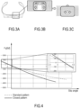
- tyre compression stiffness is increased by reducing the distance of grooves' walls, which causes interlocking deformations of opposite faces of groove during rolling of the tyre ( Figures 3A-3C ).
- One of the trade-off of the closed pattern design is an increase of the ply-steer effect, which has a negative impact on tyre wear and irregular wear.
- the rolling resistance coefficient RRc associated to a closed pattern tyre is about 2% lower than that of a standard pattern tyre.
- a tyre crown structure is made with multiple layers of plies bonded together to realize multi-ply systems, which twist and bend when subjected to simple tensile load. The result is a combination of bending, shearing and stretching of the laminate.
- tyres generate measurable lateral force and self-aligning moment under straight rolling condition.
- Ply steer side force is an inherent property of a belted radial tyre, which is the nonzero side force at zero slip angles.
- WO2017/103431 A1 relates to a tire with a radial carcass reinforcement intended to be fitted to vehicles carrying heavy loads and traveling at sustained speed, such as trucks.
- US2019/135052 A1 is aimed to solve the problem of suppressing asymmetrical deformation of run-flat radial tires with a comparatively large tire cross-section height during run-flat running, and of increasing durability during run-flat running.
- EP3130483 A1 discloses a pneumatic tire capable of achieving steering stability, noise performance, and on-snow performance.
- the tire comprises circumferential sipes (4, 11) continuously extending in the tread circumferential direction and having a width comprised between 0.5 to 1.5 mm, to ensure the edge component against the side force direction, and improve the on-snow performance during cornering.
- US2014238568 A1 discloses a tire for use in a heavy load vehicle such as a truck, which tire exhibits good performances in both fuel efficiency and drainage thanks to the presence of narrow grooves.
- US2010147438 A1 discloses a tire with a radial carcass reinforcement, intended to be fitted to vehicles that carry heavy loads and drive at sustained speeds.
- the tire has a radial carcass reinforcement comprising a crown reinforcement formed of at least two working crown layers of inextensible reinforcing elements, crossed from one layer to the other making angles of between 10° and 45° with the circumferential direction.
- the technical problem posed and solved by the present invention is therefore to provide a tyre which allows overcoming the disadvantages mentioned above with reference to the known art.
- a tyre comprising a carcass, an external tread portion provided with a closed pattern design and at least one high elongation (HE) belt, applied as a single cord or as a strip of multiple cords, in particular arranged between bias working belts, is provided.
- HE high elongation
- High Elongation Belt refers to a belt characterized by a stiffness module variable as a function of strain.
- the stiffness module is directly proportional to the strain, that means the stiffness module is low for little strain, and higher for higher strain.
- a High Elongation Belt is a belt embedding a cord provided with a stiffness module variable between about 3.000 MPa (low modulus, from 0 to about 2% of strain or elongation) and 1.125.000 MPa (high modulus, for strain higher than about 2%), said cord having an elongation at break between 2.5% and 3.5%.
- the elongation at break being measured on a sample extracted from a vulcanized tyre.
- the at least one High Elongation Belt could be applied as a single cord or as a strip of multiple cord, for example six or nine cords.
- the above stiffness properties are not due to the belt itself, but to the single cord configuration that makes up the belt (i.e. the plurality of single cords arranged parallel to each other or the strips of six or nine cords arranged also parallel to each other).
- At least one High Elongation Belt preferably a system comprising one or at most two high elongation belts, provides great advantages with respect to the traditional belt construction.
- the at least one high elongation belt of the claimed invention is applied as a single cord strip.
- the switching from a strip of plurality of cords to a single cord strongly reduces the belt cord angle ⁇ , and moreover avoids the need of a turn on edge (no free edges).
- the at least one high elongation belt is applied at 0°, as a longitudinal belt.
- a lower asymmetry of the belt package, due to a low belt cord angle ⁇ of the HE application, will result in a lower ply-steer force.
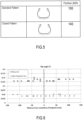
- the comparative Table 1 shows the main differences, regarding parameters such as axial width A and belt cord angle ⁇ (the angle comprised between the cord and the longitudinal direction L shown in Figures 1 and 2 ), between a prior art belt system and a preferred embodiment of belt system according to the claimed invention provided with one high elongation belt, the two compared belt systems having the same closed pattern and comprising four belts (numbered 1 to 4): Table 1.
- L and R reported near the belt cord angle values in Table 1 correspond respectively to the Left or Right direction according to which the amplitude of the concerned belt cord angle is measured, starting from the circumferential direction.
- R corresponds to an angle measured clockwise starting from the circumferential direction
- L corresponds to an angle measured counterclockwise starting from the circumferential direction.
- the combination of a closed pattern technology with the at least one high elongation belt according to the claimed tyre configuration allows to obtain a low ply-steer force, and thus low wear and irregular wear performances of the tyre.
- the application of at least one high elongation belt to a closed pattern tyre allows to neutralize the negative effects provided by the closed pattern, and to enjoy only the positive effects thereof.
- An improved tyre according to the present invention provides a new belt construction in combination with a closed pattern design of the tread, in order to balance ply-steer trade off and enhance rolling resistance RRc and wear performances, so to avoid the disadvantages of the prior art tyre having a closed pattern design.
- the tyre according to the present invention comprises an external tread portion provided with two or more grooves designed to realize a closed pattern.
- a preferred embodiment of tyre 10 comprises a tread portion 6 provided with two or more grooves 7, the grooves 7 extending according to a circumferential direction L around said tread portion 6.
- the axial width W g of at least one of said grooves 7, measured according to an axial direction A parallel to an axis of rotation R of the tyre 10 and orthogonal to said circumferential direction L, ranges from 0,5 to 4 millimeters, in particular is lower than, or at least equal to, 2 millimeters.
- the axial width W g of said groove 7 is substantially constant over the full depth of the groove.
- the radial depth D g of at least one of said grooves 7, measured according to a radial direction of the tyre 10, ranges from 7 to 14 millimeters, preferably 8 to 13 millimeters, more preferably from 9 to 12 millimeters.
- At least one of said grooves 7 is the groove closest to the tyre equatorial plane CL (or centerline CL) in a tyre axial direction.
- the tyre equatorial plane CL is the plane dividing the tread portion 6 into two eqally wide portions.
- two of said grooves 7 are the grooves closest to the tyre equatorial plane CL (or centerline CL) in a tyre axial direction.
- two of said grooves 7 are the grooves closest to the tyre equatorial plane CL (or centerline CL) in a tyre axial direction, wherein the two grooves 7 are disposed on both sides, one on each side, of the tyre equatorial plane CL (or centerline CL) in a tyre axial direction.
- two or three of said grooves 7 are disposed on both sides of the tyre equatorial plane CL (or centerline CL) in a tyre axial direction.
- said grooves 7 are positioned within a maximum axial distance from the equatorial plane CL that corresponds to 30% of the axial width W 1 , W 2 , W 3 , W 4 of the widest tread belt 1, 2, 3, 4.
- the tyre 10 according to the invention further comprises a carcass 5 (which may include one or more inner body plies), and at least one high elongation belt.
- the at least one high elongation belt is applied radially, as a single cord strip, externally to the carcass 5.
- the at least one high elongation belt is applied onto the most radially external side of an inner body ply of the tyre.
- a tyre comprising a plurality of belts radially superimposed to each other is provided, comprising one high elongation belt which corresponds to the second belt, starting from the carcass and going towards the tread portion.
- the tyre 10 comprises four belts, in particular a first, a second, a third and a fourth belt, starting from the carcass 5 and going towards the tread portion 8, respectively denoted by the numerical references 1, 2, 3, 4.
- each of the four belts 1, 2, 3, 4 is applied in such a manner to define a respective belt cord angle, denoted in Figure 1A with the references ⁇ 1 , ⁇ 2 , ⁇ 3 and ⁇ 4 respectively, and more preferably each of said belt cord angle ⁇ 1 , ⁇ 2 , ⁇ 3 , ⁇ 4 is different from the other ones.
- At least one of said first, second, third and fourth belt 1, 2, 3, 4 is a high elongation belt, applied as a single cord strip and having a belt cord angle equal to 0°. That is, the high elongation belt is configured as a longitudinal belt.
- the single cord strip is spirally applied, and thanks to such a kind of application the obtainment of a belt cord angle equal to 0° is facilitated.
- the value of each belt cord angle ⁇ 1 , ⁇ 2 , ⁇ 3 , ⁇ 4 ranges from 0° to 80°, measured with respect to the circumferential axis L.
- the belt cord angle is the lowest angle (having a positive or negative value of amplitude, wherein a positive amplitude is measured according to a clockwise direction, and a negative amplitude is measured according to a counterclockwise direction) comprised between the circumferential axis L and the cords main extension axis.
- belt cord angles ⁇ 1 and ⁇ 4 are shown having an amplitude equal to about 45°, according to a counterclockwise direction.
- the second belt 2 is provided as a high elongation belt, applied as a single cord strip and being configured to define, as already said, a second belt cord angle ⁇ 2 equal to 0°.
- the tyre 10 comprises a first belt 1, defining a first belt cord angle ⁇ 1 ranging from 35° to 60°; a second high elongation belt 2, defining a second belt cord angle ⁇ 2 equal to 0°; a third belt 3, defining a third belt cord angle ⁇ 3 ranging from 20° to 40°; and a fourth belt 4, defining a fourth belt cord angle ⁇ 4 ranging from 40° to 60°.
- the ratio between the angles of the belts with respect to the first belt cord angle ⁇ 1 is defined as follows:
- the first belt 1 defines a first belt cord angle ⁇ 1 equal to 40°
- the second belt 2 defines a second belt cord angle ⁇ 2 equal to 0°
- the third belt 3 defines a third belt cord angle ⁇ 3 equal to 28°
- the fourth belt 4 defines a belt cord angle ⁇ 4 equal to 52°.
- only the first belt 1 is a high elongation belt, being applied as a single cord strip and defining, according to such an embodiment, a first belt cord angle ⁇ 1 equal to 0°.
- both the first and the second belts 1, 2 are high elongation belts, being applied as a single cord strip and defining, respectively, a first ⁇ 1 and a second ⁇ 2 belt cord angle equal to 0°.
- each of said first, second, third and fourth belt 1, 2, 3, 4 has a respective width W 1 , W 2 , W 3 , W 4 , measured according said axial direction A, which ranges from 100 to 300 millimeters. According to a preferred embodiment of the invention, said width could range from 130 to 250 millimeters.
- the ratio between said width W 2 , W 3 , W 4 of the second, third and fourth belt 2, 3, 4 with respect to said width W 1 of the first belt 1 is defined as follows:
- the first belt 1 has a first width W 1 equal to 230 millimeters
- the second belt 2 has a second width W 2 equal to 215 millimeters
- the third belt 3 has a third width W 3 equal to 250 millimeters
- the fourth belt 4 has a fourth width W 4 equal to 130 millimeters.
- the four belts 1, 2, 3, 4 are radially superimposed to each other in such a manner to realize a sandwich structure or belt system.
- the first belt 1 is at an innermost position and the fourth belt 4 is at an outermost position with respect to the other belts 2, 3.
- the second belt 2 is interposed between the first 1 and the third belt 3, whereas the third belt 3 is interposed between the second belt 2 and the fourth belt 4.
- the tyre according to the embodiments above disclosed is particularly intended to be a truck or bus tyre.
Landscapes
- Engineering & Computer Science (AREA)
- Mechanical Engineering (AREA)
- Tires In General (AREA)
Claims (18)
- Reifen (10), umfassend:- eine Karkasse (5);- mindestens einen Gürtel (2) mit hoher Dehnung, der als ein einzelner Cordstreifen an der Karkasse (5) radial extern angebracht ist,
wobei der Gürtel (2) mit hoher Dehnung einen Cord einbettet, der mit einem Steifigkeitsmodul versehen ist, der zwischen etwa 3.000 MPa für einen Verformungsbetrag des Cords, der von 0 bis etwa 2 % reicht, und 125.000 MPa für einen Verformungsbetrag des Cords höher als etwa 2 % variabel ist; und- einen externen Laufflächenabschnitt (6), der mit zwei oder mehr Rillen (7) versehen ist, die sich gemäß einer Umfangsrichtung (L) um den Laufflächenabschnitt (6) herum erstrecken,wobei die Axialbreite (Wg) von beiden der Rillen (7), gemessen gemäß einer Axialrichtung (A) parallel zu einer Rotationsachse (R) des Reifens (10) und orthogonal zu der Umfangsrichtung (L), kleiner als oder mindestens gleich 2 Millimeter ist.der Reifen (10) umfassend einen ersten Gürtel (1), einen zweiten Gürtel (2), einen dritten Gürtel (3) und einen vierten Gürtel (4), die je einen jeweiligen Gürtelcordwinkel (θ1, θ2, θ3, θ4), aufweisen, wobei mindestens einer des ersten, des zweiten, des dritten und des vierten Gürtels (1, 2, 3, 4) ein Gürtel (2) mit hoher Dehnung ist, der als ein einzelner Cordstreifen angebracht ist und einen Gürtelcordwinkel (θ2) gleich 0° aufweist,wobei das Verhältnis zwischen den Winkeln der Gürtel in Bezug auf den ersten Gürtelcordwinkel (θ1) wie folgt definiert ist:- der zweite Gürtelcordwinkel (θ2) gleicht 0°;- der dritte Gürtelcordwinkel (θ3) gleicht zu 60 % - 80 %, vorzugsweise zu 70 %, dem ersten Gürtelcordwinkel (θ1) und- der vierte Gürtelcordwinkel (θ4) gleicht zu 120 % - 140 %, vorzugsweise zu 130 %, dem ersten Gürtelcordwinkel (θ1) - Reifen (10) nach Anspruch 1, wobei der Cord, der in dem Gürtel (2) mit hoher Dehnung eingebettet ist, eine Bruchdehnung zwischen 2,5 % und 3,5 % aufweist.
- Reifen (10) nach Anspruch 1 oder 2, wobei beide der Rillen (7) eine Tiefe in der radialen Richtung aufweisen und die Axialbreite (Wg) von beiden der Rillen (7) über die ganze Tiefe der Rillen (7) im Wesentlichen konstant ist.
- Reifen (10) nach einem der vorstehenden Ansprüche, wobei der erste, der zweite, der dritte und der vierte Gürtel (1, 2, 3, 4) beginnend von dem ersten Gürtel (1) bis zu dem vierten Gürtel (4) radial übereinander angeordnet sind, wobei der erste Gürtel (1) an einer innersten Position ist und der vierte Gürtel (4) an einer äußersten Position in Bezug auf die anderen Gürtel (2, 3) ist.
- Reifen (10) nach einem der vorstehenden Ansprüche, wobei der zweite Gürtel (2) ein Gürtel mit hoher Dehnung ist, der als ein einzelner Cordstreifen angebracht ist und einen Gürtelcordwinkel (θ2) gleich 0° aufweist.
- Reifen (10) nach einem der vorstehenden Ansprüche, umfassend:- einen ersten Gürtel (1), der einen ersten Gürtelcordwinkel (θ1), der von 35° bis 60° reicht, definiert;- einen zweiten Gürtel (2) mit hoher Dehnung, der einen zweiten Gürtelcordwinkel (θ2) gleich 0° definiert;- einen dritten Gürtel (3), der einen dritten Gürtelcordwinkel (θ3), der von 20° bis 40° reicht, definiert; und- einen vierten Gürtel (4), der einen vierten Gürtelcordwinkel (θ4), der von 40° bis 60° reicht, definiert.
- Reifen (10) nach Anspruch 6, wobei:- der erste Gürtelcordwinkel (θ1) gleich 40° ist;- der dritte Gürtelcordwinkel (θ3) gleich 28° ist; und- der vierte Gürtelcordwinkel (θ4) gleich 52° ist.
- Reifen (10) nach einem der vorstehenden Ansprüche, wobei jeder des ersten, des zweiten, des dritten und des vierten Gürtels (1, 2, 3, 4) eine jeweilige Breite (W1, W2, W3, W4), gemessen gemäß der Axialrichtung (A), aufweist, die von 100 bis 300 Millimeter reicht.
- Reifen (10) nach Anspruch 8, wobei die Breite (W1, W2, W3, W4) von 130 bis 250 Millimeter reicht.
- Reifen (10) nach Anspruch 8 oder 9, wobei das Verhältnis zwischen der Breite (W2, W3, W4) des zweiten, des dritten und des vierten Gürtels (2, 3, 4) in Bezug auf die Breite (W1) des ersten Gürtels (1) wie folgt definiert ist:- die Breite (W2) des zweiten Gürtels (2) gleicht zu 85 % - 100 %, vorzugsweise zu 92 % - 94 %, der Breite (W1) des ersten Gürtels (1),- die Breite (W3) des dritten Gürtels gleicht zu 95 % - 115 %, vorzugsweise zu 107 % - 109 %, der Breite (W1) des ersten Gürtels (1) und- die Breite (W4) des vierten Gürtels (4) gleicht zu 45 % - 60 %, vorzugsweise zu 55 % - 57 %, der Breite (W1) des ersten Gürtels (1).
- Reifen (10) nach Anspruch 9, umfassend:- einen ersten Gürtel (1), der eine erste Breite (W1) gleich 230 Millimeter aufweist;- einen zweiten Gürtel (2), der eine zweite Breite (W2) gleich 215 Millimeter aufweist,- einen dritten Gürtel (3), der eine dritte Breite (W3) gleich 250 Millimeter aufweist; und- einen vierten Gürtel (4), der eine vierte Breite (W4) gleich 130 Millimeter aufweist.
- Reifen (10) nach Anspruch 4, wobei der erste Gürtel (1) ein Gürtel mit hoher Dehnung ist, der als ein einzelner Cordstreifen angebracht ist und einen Gürtelcordwinkel (θ1) gleich 0° aufweist.
- Reifen (10) nach Anspruch 12, wobei der erste und der zweite Gürtel (1, 2) beide Gürtel mit hoher Dehnung sind, die als ein einzelner Cordstreifen angebracht sind und einen Gürtelcordwinkel (θ1, θ2) gleich 0° definieren.
- Reifen (10) nach einem der vorstehenden Ansprüche, wobei zwei der zwei oder mehr Rillen (7) die Rillen sind, die am nächsten zu einer Reifenäquatorialebene (CL) in einer Reifenaxialrichtung sind.
- Reifen (10) nach Anspruch 14, wobei die zwei Rillen (7) mit einer auf jeder Seite der Reifenäquatorialebene (CL) in einer Reifenaxialrichtung eingerichtet sind.
- Reifen (10) nach Anspruch 15, wobei mehr als 1 Rille (7) auf jeder Seite der Äquatorialebene (CL) in einer Reifenaxialrichtung eingerichtet ist.
- Reifen (10) nach Anspruch 15 oder 16, wobei zwischen einer und drei Rillen (7) auf jeder Seite der Äquatorialebene (CL) in einer Reifenaxialrichtung eingerichtet sind.
- Reifen (10) nach einem der vorstehenden Ansprüche, der ein Lastkraftwagenreifen ist.
Applications Claiming Priority (2)
| Application Number | Priority Date | Filing Date | Title |
|---|---|---|---|
| EP20170043.2A EP3895913A1 (de) | 2020-04-17 | 2020-04-17 | Verbesserter reifen |
| PCT/EP2021/059907 WO2021209598A1 (en) | 2020-04-17 | 2021-04-16 | Improved tyre |
Publications (2)
| Publication Number | Publication Date |
|---|---|
| EP4135988A1 EP4135988A1 (de) | 2023-02-22 |
| EP4135988B1 true EP4135988B1 (de) | 2024-10-09 |
Family
ID=70295000
Family Applications (2)
| Application Number | Title | Priority Date | Filing Date |
|---|---|---|---|
| EP20170043.2A Pending EP3895913A1 (de) | 2020-04-17 | 2020-04-17 | Verbesserter reifen |
| EP21719136.0A Active EP4135988B1 (de) | 2020-04-17 | 2021-04-16 | Verbesserter reifen |
Family Applications Before (1)
| Application Number | Title | Priority Date | Filing Date |
|---|---|---|---|
| EP20170043.2A Pending EP3895913A1 (de) | 2020-04-17 | 2020-04-17 | Verbesserter reifen |
Country Status (5)
| Country | Link |
|---|---|
| US (1) | US12285981B2 (de) |
| EP (2) | EP3895913A1 (de) |
| JP (1) | JP7503147B2 (de) |
| CN (1) | CN115702082B (de) |
| WO (1) | WO2021209598A1 (de) |
Families Citing this family (1)
| Publication number | Priority date | Publication date | Assignee | Title |
|---|---|---|---|---|
| JP2023180553A (ja) * | 2022-06-09 | 2023-12-21 | 住友ゴム工業株式会社 | タイヤ |
Family Cites Families (23)
| Publication number | Priority date | Publication date | Assignee | Title |
|---|---|---|---|---|
| US2699193A (en) * | 1951-07-12 | 1955-01-11 | Cymax Corp | Pneumatic tire |
| IT1223508B (it) * | 1987-12-17 | 1990-09-19 | Pirelli | Struttura di cintura di pneumatici per ruote di veicoli |
| FR2719257B1 (fr) * | 1994-04-28 | 1996-07-19 | Dunlop Sa | Pneumatique radial renforcé pour poids lourd. |
| US6851463B1 (en) * | 1999-04-08 | 2005-02-08 | Alliedsignal Inc. | Composite comprising organic fibers having a low twist multiplier and improved compressive modulus |
| BRPI0412723B1 (pt) | 2003-07-18 | 2013-12-24 | Michelin Rech Tech | Pneumático com armação de carcaça radial |
| PL1646750T3 (pl) * | 2003-07-22 | 2008-09-30 | N V Bekaert Sa | Hybrydowy wysoce rozciągliwy kord |
| JP2007217807A (ja) * | 2006-02-15 | 2007-08-30 | Bridgestone Corp | スチールコード、ゴム−スチールコード複合体およびタイヤ |
| EP2123483B1 (de) | 2006-12-26 | 2017-06-07 | Bridgestone Corporation | Luftreifen |
| FR2916160B1 (fr) * | 2007-05-14 | 2009-07-17 | Michelin Soc Tech | Pneumatique pour vehicules lourds |
| CN102369321B (zh) * | 2009-04-03 | 2014-08-13 | 贝卡尔特公司 | 具有预成形股的高伸长率钢帘线 |
| FR2943950B1 (fr) | 2009-04-07 | 2011-04-15 | Michelin Soc Tech | Pneumatique pour vehicules lourds comportant une couche d'element circonferentiels. |
| BRPI1014590B1 (pt) * | 2009-04-22 | 2020-02-27 | Pirelli Tyre S.P.A. | Pneu para rodas de veículo de carga pesada |
| DE102011000703A1 (de) * | 2011-02-14 | 2012-08-16 | Continental Reifen Deutschland Gmbh | Verfahren zur Herstellung eines Fahrzeugluftreifens |
| US8550134B2 (en) * | 2011-03-02 | 2013-10-08 | The Goodyear Tire & Rubber Company | Low aspect ratio super single truck tire with a split breaker |
| US20140238568A1 (en) * | 2011-10-03 | 2014-08-28 | Bridgestone Corporation | Pneumatic tire for heavy load |
| DE102014209423A1 (de) * | 2014-05-19 | 2015-11-19 | Continental Reifen Deutschland Gmbh | Fahrzeugluftreifen |
| US10195904B2 (en) * | 2014-05-29 | 2019-02-05 | Bridgestone Corporation | Pneumatic tire |
| JP6557064B2 (ja) | 2015-06-18 | 2019-08-07 | 株式会社ブリヂストン | 重荷重用タイヤ |
| FR3045486B1 (fr) * | 2015-12-16 | 2017-12-22 | Michelin & Cie | Pneumatique presentant des proprietes d'usure ameliorees |
| JP6684644B2 (ja) * | 2016-04-28 | 2020-04-22 | 株式会社ブリヂストン | ランフラットラジアルタイヤ |
| JP6805561B2 (ja) | 2016-06-13 | 2020-12-23 | 横浜ゴム株式会社 | 空気入りタイヤ |
| DE102017215186A1 (de) * | 2017-08-30 | 2019-02-28 | Continental Reifen Deutschland Gmbh | Fahrzeugluftreifen |
| JP7077619B2 (ja) | 2017-12-28 | 2022-05-31 | 横浜ゴム株式会社 | 空気入りタイヤ |
-
2020
- 2020-04-17 EP EP20170043.2A patent/EP3895913A1/de active Pending
-
2021
- 2021-04-16 CN CN202180040327.XA patent/CN115702082B/zh active Active
- 2021-04-16 WO PCT/EP2021/059907 patent/WO2021209598A1/en not_active Ceased
- 2021-04-16 EP EP21719136.0A patent/EP4135988B1/de active Active
- 2021-04-16 US US17/919,361 patent/US12285981B2/en active Active
- 2021-04-16 JP JP2022562888A patent/JP7503147B2/ja active Active
Also Published As
| Publication number | Publication date |
|---|---|
| WO2021209598A1 (en) | 2021-10-21 |
| EP3895913A1 (de) | 2021-10-20 |
| JP2023522875A (ja) | 2023-06-01 |
| US20230150311A1 (en) | 2023-05-18 |
| CN115702082A (zh) | 2023-02-14 |
| US12285981B2 (en) | 2025-04-29 |
| CN115702082B (zh) | 2025-05-06 |
| JP7503147B2 (ja) | 2024-06-19 |
| EP4135988A1 (de) | 2023-02-22 |
Similar Documents
| Publication | Publication Date | Title |
|---|---|---|
| EP2113398B1 (de) | Radialluftreifen | |
| EP2213484B1 (de) | Luftreifen | |
| US10183531B2 (en) | Pneumatic tire | |
| EP2676812B1 (de) | Luftreifen | |
| US8800619B2 (en) | Tire | |
| EP2123483B1 (de) | Luftreifen | |
| CN103764411B (zh) | 充气轮胎 | |
| US9987883B2 (en) | Pneumatic tire | |
| EP2979900B1 (de) | Schwerlastluftreifen | |
| EP2957435B1 (de) | Schwerlastreifen | |
| EP2641751B1 (de) | Landwirtschaftsreifen | |
| EP2623336A1 (de) | Luftreifen | |
| EP3141404B1 (de) | Luftreifen | |
| US9950570B2 (en) | Pneumatic tire | |
| EP4135988B1 (de) | Verbesserter reifen | |
| JP5308781B2 (ja) | 空気入りタイヤ | |
| JP3973414B2 (ja) | 空気入りラジアルタイヤ | |
| JP2009173131A (ja) | 空気入りタイヤ | |
| WO2024185192A1 (ja) | 空気入りタイヤ | |
| JP6077736B2 (ja) | 空気入りタイヤ | |
| JP7813126B2 (ja) | 空気入りタイヤ | |
| JP7278899B2 (ja) | 空気入りタイヤ | |
| CN120569298A (zh) | 土木工程轮胎的优化结构 | |
| EP2248682A1 (de) | Reifen ohne spikes | |
| JP2025024553A (ja) | 空気入りタイヤ |
Legal Events
| Date | Code | Title | Description |
|---|---|---|---|
| STAA | Information on the status of an ep patent application or granted ep patent |
Free format text: STATUS: UNKNOWN |
|
| STAA | Information on the status of an ep patent application or granted ep patent |
Free format text: STATUS: THE INTERNATIONAL PUBLICATION HAS BEEN MADE |
|
| PUAI | Public reference made under article 153(3) epc to a published international application that has entered the european phase |
Free format text: ORIGINAL CODE: 0009012 |
|
| STAA | Information on the status of an ep patent application or granted ep patent |
Free format text: STATUS: REQUEST FOR EXAMINATION WAS MADE |
|
| 17P | Request for examination filed |
Effective date: 20221117 |
|
| AK | Designated contracting states |
Kind code of ref document: A1 Designated state(s): AL AT BE BG CH CY CZ DE DK EE ES FI FR GB GR HR HU IE IS IT LI LT LU LV MC MK MT NL NO PL PT RO RS SE SI SK SM TR |
|
| RAP3 | Party data changed (applicant data changed or rights of an application transferred) |
Owner name: BRIDGESTONE EUROPE NV/SA |
|
| DAV | Request for validation of the european patent (deleted) | ||
| DAX | Request for extension of the european patent (deleted) | ||
| GRAP | Despatch of communication of intention to grant a patent |
Free format text: ORIGINAL CODE: EPIDOSNIGR1 |
|
| STAA | Information on the status of an ep patent application or granted ep patent |
Free format text: STATUS: GRANT OF PATENT IS INTENDED |
|
| INTG | Intention to grant announced |
Effective date: 20240429 |
|
| GRAS | Grant fee paid |
Free format text: ORIGINAL CODE: EPIDOSNIGR3 |
|
| GRAA | (expected) grant |
Free format text: ORIGINAL CODE: 0009210 |
|
| STAA | Information on the status of an ep patent application or granted ep patent |
Free format text: STATUS: THE PATENT HAS BEEN GRANTED |
|
| AK | Designated contracting states |
Kind code of ref document: B1 Designated state(s): AL AT BE BG CH CY CZ DE DK EE ES FI FR GB GR HR HU IE IS IT LI LT LU LV MC MK MT NL NO PL PT RO RS SE SI SK SM TR |
|
| REG | Reference to a national code |
Ref country code: CH Ref legal event code: EP |
|
| REG | Reference to a national code |
Ref country code: DE Ref legal event code: R096 Ref document number: 602021019945 Country of ref document: DE |
|
| REG | Reference to a national code |
Ref country code: IE Ref legal event code: FG4D |
|
| REG | Reference to a national code |
Ref country code: LT Ref legal event code: MG9D |
|
| REG | Reference to a national code |
Ref country code: NL Ref legal event code: MP Effective date: 20241009 |
|
| REG | Reference to a national code |
Ref country code: AT Ref legal event code: MK05 Ref document number: 1730208 Country of ref document: AT Kind code of ref document: T Effective date: 20241009 |
|
| PG25 | Lapsed in a contracting state [announced via postgrant information from national office to epo] |
Ref country code: NL Free format text: LAPSE BECAUSE OF FAILURE TO SUBMIT A TRANSLATION OF THE DESCRIPTION OR TO PAY THE FEE WITHIN THE PRESCRIBED TIME-LIMIT Effective date: 20241009 |
|
| PG25 | Lapsed in a contracting state [announced via postgrant information from national office to epo] |
Ref country code: NL Free format text: LAPSE BECAUSE OF FAILURE TO SUBMIT A TRANSLATION OF THE DESCRIPTION OR TO PAY THE FEE WITHIN THE PRESCRIBED TIME-LIMIT Effective date: 20241009 |
|
| P01 | Opt-out of the competence of the unified patent court (upc) registered |
Free format text: CASE NUMBER: APP_8766/2025 Effective date: 20250220 |
|
| PG25 | Lapsed in a contracting state [announced via postgrant information from national office to epo] |
Ref country code: PT Free format text: LAPSE BECAUSE OF FAILURE TO SUBMIT A TRANSLATION OF THE DESCRIPTION OR TO PAY THE FEE WITHIN THE PRESCRIBED TIME-LIMIT Effective date: 20250210 Ref country code: HR Free format text: LAPSE BECAUSE OF FAILURE TO SUBMIT A TRANSLATION OF THE DESCRIPTION OR TO PAY THE FEE WITHIN THE PRESCRIBED TIME-LIMIT Effective date: 20241009 Ref country code: IS Free format text: LAPSE BECAUSE OF FAILURE TO SUBMIT A TRANSLATION OF THE DESCRIPTION OR TO PAY THE FEE WITHIN THE PRESCRIBED TIME-LIMIT Effective date: 20250209 |
|
| PG25 | Lapsed in a contracting state [announced via postgrant information from national office to epo] |
Ref country code: FI Free format text: LAPSE BECAUSE OF FAILURE TO SUBMIT A TRANSLATION OF THE DESCRIPTION OR TO PAY THE FEE WITHIN THE PRESCRIBED TIME-LIMIT Effective date: 20241009 |
|
| PG25 | Lapsed in a contracting state [announced via postgrant information from national office to epo] |
Ref country code: BG Free format text: LAPSE BECAUSE OF FAILURE TO SUBMIT A TRANSLATION OF THE DESCRIPTION OR TO PAY THE FEE WITHIN THE PRESCRIBED TIME-LIMIT Effective date: 20241009 |
|
| PG25 | Lapsed in a contracting state [announced via postgrant information from national office to epo] |
Ref country code: ES Free format text: LAPSE BECAUSE OF FAILURE TO SUBMIT A TRANSLATION OF THE DESCRIPTION OR TO PAY THE FEE WITHIN THE PRESCRIBED TIME-LIMIT Effective date: 20241009 |
|
| PG25 | Lapsed in a contracting state [announced via postgrant information from national office to epo] |
Ref country code: NO Free format text: LAPSE BECAUSE OF FAILURE TO SUBMIT A TRANSLATION OF THE DESCRIPTION OR TO PAY THE FEE WITHIN THE PRESCRIBED TIME-LIMIT Effective date: 20250109 |
|
| PG25 | Lapsed in a contracting state [announced via postgrant information from national office to epo] |
Ref country code: LV Free format text: LAPSE BECAUSE OF FAILURE TO SUBMIT A TRANSLATION OF THE DESCRIPTION OR TO PAY THE FEE WITHIN THE PRESCRIBED TIME-LIMIT Effective date: 20241009 Ref country code: GR Free format text: LAPSE BECAUSE OF FAILURE TO SUBMIT A TRANSLATION OF THE DESCRIPTION OR TO PAY THE FEE WITHIN THE PRESCRIBED TIME-LIMIT Effective date: 20250110 Ref country code: AT Free format text: LAPSE BECAUSE OF FAILURE TO SUBMIT A TRANSLATION OF THE DESCRIPTION OR TO PAY THE FEE WITHIN THE PRESCRIBED TIME-LIMIT Effective date: 20241009 |
|
| PG25 | Lapsed in a contracting state [announced via postgrant information from national office to epo] |
Ref country code: PL Free format text: LAPSE BECAUSE OF FAILURE TO SUBMIT A TRANSLATION OF THE DESCRIPTION OR TO PAY THE FEE WITHIN THE PRESCRIBED TIME-LIMIT Effective date: 20241009 |
|
| PG25 | Lapsed in a contracting state [announced via postgrant information from national office to epo] |
Ref country code: RS Free format text: LAPSE BECAUSE OF FAILURE TO SUBMIT A TRANSLATION OF THE DESCRIPTION OR TO PAY THE FEE WITHIN THE PRESCRIBED TIME-LIMIT Effective date: 20250109 |
|
| PG25 | Lapsed in a contracting state [announced via postgrant information from national office to epo] |
Ref country code: SM Free format text: LAPSE BECAUSE OF FAILURE TO SUBMIT A TRANSLATION OF THE DESCRIPTION OR TO PAY THE FEE WITHIN THE PRESCRIBED TIME-LIMIT Effective date: 20241009 |
|
| PGFP | Annual fee paid to national office [announced via postgrant information from national office to epo] |
Ref country code: DE Payment date: 20250319 Year of fee payment: 5 |
|
| PG25 | Lapsed in a contracting state [announced via postgrant information from national office to epo] |
Ref country code: DK Free format text: LAPSE BECAUSE OF FAILURE TO SUBMIT A TRANSLATION OF THE DESCRIPTION OR TO PAY THE FEE WITHIN THE PRESCRIBED TIME-LIMIT Effective date: 20241009 |
|
| REG | Reference to a national code |
Ref country code: DE Ref legal event code: R097 Ref document number: 602021019945 Country of ref document: DE |
|
| PG25 | Lapsed in a contracting state [announced via postgrant information from national office to epo] |
Ref country code: EE Free format text: LAPSE BECAUSE OF FAILURE TO SUBMIT A TRANSLATION OF THE DESCRIPTION OR TO PAY THE FEE WITHIN THE PRESCRIBED TIME-LIMIT Effective date: 20241009 |
|
| PG25 | Lapsed in a contracting state [announced via postgrant information from national office to epo] |
Ref country code: RO Free format text: LAPSE BECAUSE OF FAILURE TO SUBMIT A TRANSLATION OF THE DESCRIPTION OR TO PAY THE FEE WITHIN THE PRESCRIBED TIME-LIMIT Effective date: 20241009 |
|
| PG25 | Lapsed in a contracting state [announced via postgrant information from national office to epo] |
Ref country code: SK Free format text: LAPSE BECAUSE OF FAILURE TO SUBMIT A TRANSLATION OF THE DESCRIPTION OR TO PAY THE FEE WITHIN THE PRESCRIBED TIME-LIMIT Effective date: 20241009 |
|
| PG25 | Lapsed in a contracting state [announced via postgrant information from national office to epo] |
Ref country code: CZ Free format text: LAPSE BECAUSE OF FAILURE TO SUBMIT A TRANSLATION OF THE DESCRIPTION OR TO PAY THE FEE WITHIN THE PRESCRIBED TIME-LIMIT Effective date: 20241009 |
|
| PLBE | No opposition filed within time limit |
Free format text: ORIGINAL CODE: 0009261 |
|
| STAA | Information on the status of an ep patent application or granted ep patent |
Free format text: STATUS: NO OPPOSITION FILED WITHIN TIME LIMIT |
|
| PG25 | Lapsed in a contracting state [announced via postgrant information from national office to epo] |
Ref country code: SE Free format text: LAPSE BECAUSE OF FAILURE TO SUBMIT A TRANSLATION OF THE DESCRIPTION OR TO PAY THE FEE WITHIN THE PRESCRIBED TIME-LIMIT Effective date: 20241009 |
|
| 26N | No opposition filed |
Effective date: 20250710 |
|
| REG | Reference to a national code |
Ref country code: CH Ref legal event code: H13 Free format text: ST27 STATUS EVENT CODE: U-0-0-H10-H13 (AS PROVIDED BY THE NATIONAL OFFICE) Effective date: 20251125 |
|
| PG25 | Lapsed in a contracting state [announced via postgrant information from national office to epo] |
Ref country code: LU Free format text: LAPSE BECAUSE OF NON-PAYMENT OF DUE FEES Effective date: 20250416 |
|
| PG25 | Lapsed in a contracting state [announced via postgrant information from national office to epo] |
Ref country code: MC Free format text: LAPSE BECAUSE OF FAILURE TO SUBMIT A TRANSLATION OF THE DESCRIPTION OR TO PAY THE FEE WITHIN THE PRESCRIBED TIME-LIMIT Effective date: 20241009 |
|
| REG | Reference to a national code |
Ref country code: BE Ref legal event code: MM Effective date: 20250430 |
|
| PG25 | Lapsed in a contracting state [announced via postgrant information from national office to epo] |
Ref country code: BE Free format text: LAPSE BECAUSE OF NON-PAYMENT OF DUE FEES Effective date: 20250430 |
|
| PG25 | Lapsed in a contracting state [announced via postgrant information from national office to epo] |
Ref country code: CH Free format text: LAPSE BECAUSE OF NON-PAYMENT OF DUE FEES Effective date: 20250430 |
|
| PGFP | Annual fee paid to national office [announced via postgrant information from national office to epo] |
Ref country code: GB Payment date: 20260319 Year of fee payment: 6 |
|
| PG25 | Lapsed in a contracting state [announced via postgrant information from national office to epo] |
Ref country code: IE Free format text: LAPSE BECAUSE OF NON-PAYMENT OF DUE FEES Effective date: 20250416 |
|
| PGFP | Annual fee paid to national office [announced via postgrant information from national office to epo] |
Ref country code: IT Payment date: 20260319 Year of fee payment: 6 |
|
| PGFP | Annual fee paid to national office [announced via postgrant information from national office to epo] |
Ref country code: FR Payment date: 20260320 Year of fee payment: 6 |
|
| PGFP | Annual fee paid to national office [announced via postgrant information from national office to epo] |
Ref country code: TR Payment date: 20260325 Year of fee payment: 6 |