EP4136003B1 - Einschersicheres adaptives geschwindigkeitsregelsystem für fahrzeuge - Google Patents
Einschersicheres adaptives geschwindigkeitsregelsystem für fahrzeuge Download PDFInfo
- Publication number
- EP4136003B1 EP4136003B1 EP21710970.1A EP21710970A EP4136003B1 EP 4136003 B1 EP4136003 B1 EP 4136003B1 EP 21710970 A EP21710970 A EP 21710970A EP 4136003 B1 EP4136003 B1 EP 4136003B1
- Authority
- EP
- European Patent Office
- Prior art keywords
- acceleration
- vehicle
- distance
- emergency
- comfort
- Prior art date
- Legal status (The legal status is an assumption and is not a legal conclusion. Google has not performed a legal analysis and makes no representation as to the accuracy of the status listed.)
- Active
Links
Images



Classifications
-
- B—PERFORMING OPERATIONS; TRANSPORTING
- B60—VEHICLES IN GENERAL
- B60W—CONJOINT CONTROL OF VEHICLE SUB-UNITS OF DIFFERENT TYPE OR DIFFERENT FUNCTION; CONTROL SYSTEMS SPECIALLY ADAPTED FOR HYBRID VEHICLES; ROAD VEHICLE DRIVE CONTROL SYSTEMS FOR PURPOSES NOT RELATED TO THE CONTROL OF A PARTICULAR SUB-UNIT
- B60W30/00—Purposes of road vehicle drive control systems not related to the control of a particular sub-unit, e.g. of systems using conjoint control of vehicle sub-units
- B60W30/14—Adaptive cruise control
- B60W30/16—Control of distance between vehicles, e.g. keeping a distance to preceding vehicle
-
- B—PERFORMING OPERATIONS; TRANSPORTING
- B60—VEHICLES IN GENERAL
- B60W—CONJOINT CONTROL OF VEHICLE SUB-UNITS OF DIFFERENT TYPE OR DIFFERENT FUNCTION; CONTROL SYSTEMS SPECIALLY ADAPTED FOR HYBRID VEHICLES; ROAD VEHICLE DRIVE CONTROL SYSTEMS FOR PURPOSES NOT RELATED TO THE CONTROL OF A PARTICULAR SUB-UNIT
- B60W30/00—Purposes of road vehicle drive control systems not related to the control of a particular sub-unit, e.g. of systems using conjoint control of vehicle sub-units
- B60W30/08—Active safety systems predicting or avoiding probable or impending collision or attempting to minimise its consequences
- B60W30/09—Taking automatic action to avoid collision, e.g. braking and steering
-
- B—PERFORMING OPERATIONS; TRANSPORTING
- B60—VEHICLES IN GENERAL
- B60W—CONJOINT CONTROL OF VEHICLE SUB-UNITS OF DIFFERENT TYPE OR DIFFERENT FUNCTION; CONTROL SYSTEMS SPECIALLY ADAPTED FOR HYBRID VEHICLES; ROAD VEHICLE DRIVE CONTROL SYSTEMS FOR PURPOSES NOT RELATED TO THE CONTROL OF A PARTICULAR SUB-UNIT
- B60W30/00—Purposes of road vehicle drive control systems not related to the control of a particular sub-unit, e.g. of systems using conjoint control of vehicle sub-units
- B60W30/08—Active safety systems predicting or avoiding probable or impending collision or attempting to minimise its consequences
- B60W30/095—Predicting travel path or likelihood of collision
-
- B—PERFORMING OPERATIONS; TRANSPORTING
- B60—VEHICLES IN GENERAL
- B60W—CONJOINT CONTROL OF VEHICLE SUB-UNITS OF DIFFERENT TYPE OR DIFFERENT FUNCTION; CONTROL SYSTEMS SPECIALLY ADAPTED FOR HYBRID VEHICLES; ROAD VEHICLE DRIVE CONTROL SYSTEMS FOR PURPOSES NOT RELATED TO THE CONTROL OF A PARTICULAR SUB-UNIT
- B60W30/00—Purposes of road vehicle drive control systems not related to the control of a particular sub-unit, e.g. of systems using conjoint control of vehicle sub-units
- B60W30/08—Active safety systems predicting or avoiding probable or impending collision or attempting to minimise its consequences
- B60W30/095—Predicting travel path or likelihood of collision
- B60W30/0953—Predicting travel path or likelihood of collision the prediction being responsive to vehicle dynamic parameters
-
- B—PERFORMING OPERATIONS; TRANSPORTING
- B60—VEHICLES IN GENERAL
- B60W—CONJOINT CONTROL OF VEHICLE SUB-UNITS OF DIFFERENT TYPE OR DIFFERENT FUNCTION; CONTROL SYSTEMS SPECIALLY ADAPTED FOR HYBRID VEHICLES; ROAD VEHICLE DRIVE CONTROL SYSTEMS FOR PURPOSES NOT RELATED TO THE CONTROL OF A PARTICULAR SUB-UNIT
- B60W30/00—Purposes of road vehicle drive control systems not related to the control of a particular sub-unit, e.g. of systems using conjoint control of vehicle sub-units
- B60W30/08—Active safety systems predicting or avoiding probable or impending collision or attempting to minimise its consequences
- B60W30/095—Predicting travel path or likelihood of collision
- B60W30/0956—Predicting travel path or likelihood of collision the prediction being responsive to traffic or environmental parameters
-
- B—PERFORMING OPERATIONS; TRANSPORTING
- B60—VEHICLES IN GENERAL
- B60W—CONJOINT CONTROL OF VEHICLE SUB-UNITS OF DIFFERENT TYPE OR DIFFERENT FUNCTION; CONTROL SYSTEMS SPECIALLY ADAPTED FOR HYBRID VEHICLES; ROAD VEHICLE DRIVE CONTROL SYSTEMS FOR PURPOSES NOT RELATED TO THE CONTROL OF A PARTICULAR SUB-UNIT
- B60W2520/00—Input parameters relating to overall vehicle dynamics
- B60W2520/10—Longitudinal speed
-
- B—PERFORMING OPERATIONS; TRANSPORTING
- B60—VEHICLES IN GENERAL
- B60W—CONJOINT CONTROL OF VEHICLE SUB-UNITS OF DIFFERENT TYPE OR DIFFERENT FUNCTION; CONTROL SYSTEMS SPECIALLY ADAPTED FOR HYBRID VEHICLES; ROAD VEHICLE DRIVE CONTROL SYSTEMS FOR PURPOSES NOT RELATED TO THE CONTROL OF A PARTICULAR SUB-UNIT
- B60W2520/00—Input parameters relating to overall vehicle dynamics
- B60W2520/10—Longitudinal speed
- B60W2520/105—Longitudinal acceleration
-
- B—PERFORMING OPERATIONS; TRANSPORTING
- B60—VEHICLES IN GENERAL
- B60W—CONJOINT CONTROL OF VEHICLE SUB-UNITS OF DIFFERENT TYPE OR DIFFERENT FUNCTION; CONTROL SYSTEMS SPECIALLY ADAPTED FOR HYBRID VEHICLES; ROAD VEHICLE DRIVE CONTROL SYSTEMS FOR PURPOSES NOT RELATED TO THE CONTROL OF A PARTICULAR SUB-UNIT
- B60W2554/00—Input parameters relating to objects
- B60W2554/40—Dynamic objects, e.g. animals, windblown objects
- B60W2554/404—Characteristics
- B60W2554/4042—Longitudinal speed
-
- B—PERFORMING OPERATIONS; TRANSPORTING
- B60—VEHICLES IN GENERAL
- B60W—CONJOINT CONTROL OF VEHICLE SUB-UNITS OF DIFFERENT TYPE OR DIFFERENT FUNCTION; CONTROL SYSTEMS SPECIALLY ADAPTED FOR HYBRID VEHICLES; ROAD VEHICLE DRIVE CONTROL SYSTEMS FOR PURPOSES NOT RELATED TO THE CONTROL OF A PARTICULAR SUB-UNIT
- B60W2554/00—Input parameters relating to objects
- B60W2554/40—Dynamic objects, e.g. animals, windblown objects
- B60W2554/404—Characteristics
- B60W2554/4047—Attentiveness, e.g. distracted by mobile phone
-
- B—PERFORMING OPERATIONS; TRANSPORTING
- B60—VEHICLES IN GENERAL
- B60W—CONJOINT CONTROL OF VEHICLE SUB-UNITS OF DIFFERENT TYPE OR DIFFERENT FUNCTION; CONTROL SYSTEMS SPECIALLY ADAPTED FOR HYBRID VEHICLES; ROAD VEHICLE DRIVE CONTROL SYSTEMS FOR PURPOSES NOT RELATED TO THE CONTROL OF A PARTICULAR SUB-UNIT
- B60W2554/00—Input parameters relating to objects
- B60W2554/80—Spatial relation or speed relative to objects
-
- B—PERFORMING OPERATIONS; TRANSPORTING
- B60—VEHICLES IN GENERAL
- B60W—CONJOINT CONTROL OF VEHICLE SUB-UNITS OF DIFFERENT TYPE OR DIFFERENT FUNCTION; CONTROL SYSTEMS SPECIALLY ADAPTED FOR HYBRID VEHICLES; ROAD VEHICLE DRIVE CONTROL SYSTEMS FOR PURPOSES NOT RELATED TO THE CONTROL OF A PARTICULAR SUB-UNIT
- B60W2554/00—Input parameters relating to objects
- B60W2554/80—Spatial relation or speed relative to objects
- B60W2554/802—Longitudinal distance
-
- B—PERFORMING OPERATIONS; TRANSPORTING
- B60—VEHICLES IN GENERAL
- B60W—CONJOINT CONTROL OF VEHICLE SUB-UNITS OF DIFFERENT TYPE OR DIFFERENT FUNCTION; CONTROL SYSTEMS SPECIALLY ADAPTED FOR HYBRID VEHICLES; ROAD VEHICLE DRIVE CONTROL SYSTEMS FOR PURPOSES NOT RELATED TO THE CONTROL OF A PARTICULAR SUB-UNIT
- B60W2720/00—Output or target parameters relating to overall vehicle dynamics
- B60W2720/10—Longitudinal speed
- B60W2720/106—Longitudinal acceleration
Definitions
- the present invention is in the field of vehicle control systems.
- the invention relates to an adaptive cruise control system for a vehicle, to a vehicle equipped with such adaptive cruise control system and to a method of controlling the trajectory of a vehicle.
- Adaptive cruise control is a broadly used technology in vehicles of all kind. Following preceding vehicles is one of the most frequently-performed tasks in road traffic. To relieve drivers from this often-perceived tedious task, many vehicles are equipped with adaptive cruise control (ACC) systems, which adapt the dynamics of the vehicle to that of preceding vehicles.
- ACC adaptive cruise control
- current ACC systems are still not safe in all driving conditions and require supervision by a human driver, in particular in complex situations involving traffic interactions with other vehicles in a proximity of the vehicle in which the ACC system is installed, such as manually driven vehicles having non-predictably trajectories subject to real-time decisions by their human drivers. For example, 14.6% of traffic accidents registered in Germany in 2007 were rear-end collisions.
- WO 2004/005092 A1 discloses a driver assisting system for assisting a driver of a vehicle in danger and emergency brake situations, wherein a decision on whether an assisted braking operation should be initiated is made based on different driving parameters, such as driving speed, state of a gas pedal, state of a brake pedal and relative distance and speed with respect to one preceding vehicle.
- EP 3 121 076 A2 and US 2009/0299593 A1 describe vehicle control devices configured for controlling a vehicle so as to avoid a collision with an object either by braking the vehicle or, if braking is per se insufficient for avoiding a collision, by combining braking with steering control.
- the present invention addresses the aforementioned disadvantages of the prior art and aims at providing an ACC system that can react to a broader range of safety-risking situations without requiring the intervention of a human driver and without compromising comfort more than necessary.
- the invention refers to an adaptive cruise control (ACC) system for a vehicle according to claim 1, to a vehicle according to claim 9 and to a method of controlling a trajectory of a vehicle according to claim 10.
- ACC adaptive cruise control
- the ACC system of the invention comprises a detection module and a safety module.
- the detection module is configured for detecting one or more preceding vehicles driving ahead of the vehicle and for determining a respective velocity and a respective distance of each of the detected preceding vehicles with respect to the vehicle.
- vehicle when used herein without further indication, shall refer to the vehicle in which the ACC system is installed.
- Preceding vehicle may refer instead to a vehicle other than “the vehicle”, wherein the preceding vehicle, in particular a rearmost end thereof, such as a rear bumper, precedes the vehicle, in particular a foremost end thereof, such as a front bumper, in the direction of movement of the vehicle.
- the determined distance may hence correspond to the distance between the parts of the vehicle and the corresponding preceding vehicle that would first come into contact with each other in case of a front-end/rear-end collision between the vehicle and the preceding vehicle.
- the determined distance may for instance correspond, in each case, to a distance between the front bumper of the vehicle and the rear bumper of the corresponding preceding vehicle.
- a preceding vehicle may be aligned with the vehicle in the direction of movement of the vehicle at least within an offset limit.
- the offset limit may be chosen such that a preceding vehicle needs not be precisely aligned with the vehicle for being regarded as such. For example, if the vehicle is driving on a road with lane markings, any vehicle driving ahead of the vehicle and being, at least in part, within the same lane as the vehicle in which the ACC system is installed, may be regarded to be a preceding vehicle.
- a velocity of the preceding vehicle may hence be aligned with a velocity of the vehicle.
- the velocity of the preceding vehicle may have a component aligned with the velocity of the vehicle and a component that is not aligned with the velocity of the vehicle, for example when the preceding vehicle is changing lanes. Further, the velocity of the preceding vehicle may be zero.
- the fact that the preceding vehicles are defined as vehicles "driving" ahead of the vehicle does not necessarily imply that they must have a non-zero velocity.
- a preceding vehicle may be a moving preceding vehicle having a non-zero velocity, which may or not coincide in direction with the velocity of the vehicle, or a standing preceding vehicle having a zero-velocity. Further, any vehicle exiting the lane on which the vehicle is driving ahead of the vehicle may continue to be regarded as a preceding vehicle for a predefined time lag.
- the velocity and/or distance of the preceding vehicles may be obtained by direct measurement using one or more on-board measurement devices connected to and/or comprised in the detection module, for example radar devices, camera devices, or laser sensor devices, configured for measuring the respective velocities and/or distances of the preceding vehicles with respect to the vehicle.
- the detection module can be configured for obtaining the respective velocities and/or distances of the preceding vehicles via an exchange of information between the vehicle and the respective preceding vehicles using inter-vehicle communication systems.
- the detection module is further configured for determining whether each of the determined distances is smaller than a respective safety distance. Thus, each of the distances determined for a corresponding preceding vehicle is compared to a respective safety distance.
- the safety distances may be predefined distances, for example predefined distances stored in a table of values stored in a memory device connected to or comprised in the detection module.
- the safety distances may however also correspond, in each case, to a computed distance between the vehicle and the corresponding preceding vehicle over which the vehicle can stop, preferably from a state of maximum acceleration of the vehicle (i.e. from a state in which the acceleration of the vehicle is the maximum possible acceleration the vehicle can achieve), without a collision with the corresponding preceding vehicle in case of a full braking of the corresponding preceding vehicle, i.e. in case the corresponding preceding vehicle decelerates with a minimal acceleration that is possible or is assumed for the corresponding preceding vehicle.
- a state of maximum acceleration of the vehicle i.e. from a state in which the acceleration of the vehicle is the maximum possible acceleration the vehicle can achieve
- Such safety distance can be computed or estimated by the detection module, for example by a processing unit included in or connected to the detection module, based on the corresponding velocity determined for the corresponding preceding vehicle and based on the minimal acceleration (i.e. the maximal amplitude of a negative braking deceleration) that is assumed or is possible for the preceding vehicle.
- a predefined minimal possible acceleration may be assumed for all preceding vehicles.
- a braking deceleration according to a predefined braking acceleration modification scheme may be assumed.
- the predefined braking acceleration modification scheme may be customisable.
- Acceleration modification scheme may refer herein to a target modification of the acceleration of the vehicle, in particular over a predefined time interval, according to an arbitrary time-dependent acceleration function that respects one or more predefined boundary conditions.
- the aforesaid "predefined time interval” may correspond to a regular time interval over which the ACC system iteratively operates or to a multiple thereof.
- the customisable predefined braking acceleration modification scheme may define a predefined braking acceleration profile and/or a predefined braking jerk profile configured for optimising the comfort sensation of occupants of the vehicle, for example by not exceeding predefined acceleration and/or jerk lower and upper limits.
- the customisable predefined braking acceleration modification scheme may be stored in a storage device comprised in or connected to the ACC system.
- a storage device comprised in or connected to the ACC system.
- a time function specifying the time evolution of the jerk of the vehicle according to the braking jerk profile may be stored in such storage device.
- the acceleration of the vehicle may be bounded by a value for the minimal acceleration (i.e. the maximal amplitude of a negative braking deceleration) that can be achieved by the vehicle, which can be pre-stored in the detection module.
- the value for the minimal acceleration of the vehicle may account for dynamic properties of the vehicle that are relevant for deceleration, such as braking power, aerodynamics and/or road-tyre friction.
- the value for the minimal acceleration that can be achieved by the preceding vehicle can be a predetermined value, a value obtained from the preceding vehicle via inter-vehicle communication or a combination of both.
- the detection module may be configured for determining, based on visual imaging recognition, a manufacturer and model type or a plate registration number of the preceding vehicle and for obtaining the value for the minimal acceleration that can be achieved by the preceding vehicle from a table of values storing minimal accelerations achievable by different vehicle models of different manufacturers or registered vehicles, accordingly.
- the same predefined minimal acceleration may be assumed for any preceding vehicle.
- a situation in which the distance between the vehicle and a corresponding preceding vehicle is smaller than the respective safety distance is a situation of risk, inasmuch as, if the preceding vehicle were to perform full braking, a collision between the vehicle and the preceding vehicle could not be avoided simply by decelerating according to the predefined braking jerk profile.
- This can be the situation, for example, when a preceding vehicle cuts in into the lane on which the vehicle is driving within a distance from the vehicle smaller than the respective safety distance.
- the detection module may further be configured for determining an acceleration and/or a velocity of the vehicle.
- the detection module may be connected with a vehicle trajectory control system configured for controlling a trajectory of the vehicle, wherein the trajectory control module may comprise a motor of the vehicle, a transmission of the vehicle, a braking system of the vehicle, a velocimeter of the vehicle, an accelerometer of the vehicle and/or a wheel motion control system of the vehicle.
- the ACC system of the invention further comprises a safety module that is connected to the detection module and configured for determining, for each preceding vehicle of at least a part of the one or more detected preceding vehicles for which the determined distance is smaller than the respective safety distance, i.e. for at least some of the preceding vehicles having a distance smaller than the respective safety distance, a respective candidate target acceleration of the vehicle.
- the safety module is hence activated when at least one of the one or more preceding vehicles detected by the detection module is detected to be at a distance from the vehicle that is smaller than the respective safety distance.
- the safety module selects said at least one of the one or more preceding vehicles and determines, for each one of them, a respective candidate target acceleration of the vehicle.
- the “candidate target accelerations” may refer to constant acceleration values to be implemented at a particular point in time or time interval, in particular if the ACC system is configured to operate iteratively based on a cyclically repeated operation of the detection module and the safety module at discretised regular time intervals, such that for a regular iteration time interval ⁇ t, new "candidate target accelerations" may be determined by the safety module every time interval ⁇ t.
- the time interval ⁇ t may be for example 0,5 s or less, preferably 0,1 s or less, more preferably 0,02 s or less.
- the time interval ⁇ t may correspond to the aforesaid "predefined time interval".
- the "candidate target accelerations" may each correspond to a respective acceleration function of time a(t) to be implemented over more than one iteration time interval, over a multiple of the aforesaid iteration time intervals or over a predefined time in a non-iterative approach.
- the safety module comprises at least an ICS control unit and an emergency control unit.
- the safety module may further comprise a nominal control unit.
- the respective candidate target acceleration may be determined by the ICS control unit, the emergency control unit or by the nominal control unit.
- the ICS control unit is configured for determining whether the vehicle is or will be in an inevitable collision state ("ICS") with respect to the corresponding preceding vehicle.
- the ICS control unit can hence determine that the vehicle is currently in an ICS state or that an ICS state is possible and/or probable within a predefined time definition or within an uncertainty range of the ICS control unit and hence the vehicle will be in an ICS state.
- An "inevitable collision state" or "ICS” corresponds to a state of the vehicle in which a collision with the corresponding detected preceding vehicle is inevitable regardless of a modification of the acceleration of the vehicle.
- the safety module may define an ICS assuming for the preceding vehicles a predefined safety acceleration.
- the ICS control unit may be configured for determining whether the vehicle is in an inevitable collision state with respect to the corresponding preceding vehicle assuming a predetermined safety acceleration for the corresponding preceding vehicle.
- the safety module may hence take into account the current velocity and the minimal possible acceleration of the vehicle, as well as the determined distance and velocity of the corresponding preceding vehicle and further assume, for the preceding vehicle, the predetermined safety acceleration.
- the "minimal possible acceleration" of the vehicle may refer, not just to the maximal force that the braking system of the vehicle can physically exert on the wheels of the vehicle, but rather to the maximal effective resulting deceleration of the vehicle produced by the combined effect of all causes of deceleration and all systems involved in the deceleration, including, for example, aerodynamics, tyre-road friction and/or the intervention of an ABS system. Notably, these causes of deceleration may evolve in time, resulting in a timely varying, in particular progressively decreasing, absolute value of the minimal possible acceleration of the vehicle.
- the ICS control unit is configured for assuming an ICS state when there is no feasible control action of the vehicle that ensures that, in this scenario, a collision with the corresponding preceding vehicle at a later time is avoided. In some ICS situations, the collision may still be avoided if the corresponding preceding vehicle accelerates, however, an ICS may be assumed anyway, since whether this happens or not cannot be controlled form the vehicle.
- the ICS control unit for example a processing unit thereof, may be configured for solving the equations of motion of the vehicle and the corresponding preceding vehicle taking into account the determined velocity and distance of the corresponding preceding vehicle and taking into account the minimum possible acceleration, i.e.
- the maximal possible braking deceleration, achievable by the vehicle and the predefined safety acceleration assumed as a minimal possible acceleration of the corresponding preceding vehicle for determining whether the vehicle is in an ICS with respect to the that preceding vehicle for example using analysis tools and formulae that are known to the skilled person, for instance from S. Bouraine, T. Fraichard, H. Salhi, Provably Safe Navigation for Mobile Robots with Limited Field-of-Views in Dynamic Environments, Autonomous Robots, Springer Verlag, 2012, 32 (3), pp.267-283 .
- the ICS control unit determines that the vehicle is in an ICS with respect to a preceding vehicle, the ICS control unit is configured for determining the respective candidate target acceleration for that preceding vehicle corresponding to the minimal possible acceleration of the vehicle, i.e. to the maximal possible braking deceleration that the vehicle, in particular the braking system of the vehicle, can currently implement.
- the candidate target acceleration is determined to correspond to a full braking manoeuvre of the vehicle, such that, if the vehicle immediately implements the candidate target acceleration, i.e. the minimal possible acceleration in this case, the collision is mitigated by decelerating the vehicle as much as possible in the shortest possible time.
- the time derivative of the acceleration (the jerk) of the vehicle may be unbounded and may correspond to the minimal possible value of the time derivative of the acceleration of the vehicle, i.e. the minimal possible jerk achievable by the vehicle.
- the emergency control unit assumes an ICS, all efforts are directed to mitigating the collision without taking comfort into account: both the acceleration and the jerk of the vehicle can take up values down to the respective minimal values.
- the emergency control unit is configured for determining the candidate target acceleration if the ICS control unit determines that the vehicle is not in an inevitable collision state with respect to the corresponding preceding vehicle, according to an emergency acceleration modification scheme.
- the emergency acceleration modification scheme is hence defined for achieving the respective safety distance within a predefined time and/or without the acceleration of the vehicle falling below a first predefined acceleration lower limit.
- the acceleration of the vehicle can evolve in different ways but it is always guaranteed - mathematically speaking by imposing corresponding constraints when solving the equations of motion of the vehicle - that the acceleration of the vehicle is modified such that the respective safety distance is achieved within the predefined time and/or such that the value of the acceleration of the vehicle is always greater than or equal to the first predefined acceleration lower limit.
- the predefined time may set a time limit within which the vehicle has to establish the corresponding safety distance, in particular without the acceleration of the vehicle falling below the first predefined acceleration lower limit.
- the value of the predefined time may be user-defined, for example a predefined time of 1 s or less.
- the emergency control unit may be configured for selecting, out of all possible values of the candidate target acceleration, the value having the smallest possible absolute value, such that a variation with respect to a current acceleration of the vehicle is minimised, i.e. such that the jerk of the vehicle is as close to 0 as possible. Additionally or alternatively, the emergency control unit may be configured for selecting one candidate value among said possible values of the candidate target acceleration according to another optimisation criterion, such as minimising energy consumption.
- the vehicle Since an ICS has been discarded by the ICS control unit, the vehicle is in a situation in which the respective safety distance may be established by the emergency control unit without necessarily performing a full-braking of the vehicle, thereby keeping some degree of comfort.
- the ACC system according to the invention hence allows determining a candidate target acceleration of the vehicle for modifying the trajectory of a vehicle, in particular an acceleration and a velocity thereof, in different manners according to different situations, thereby permitting to adapt a comfort level depending on the safety requirements of the different situations.
- the respective safety distance can still be established before a collision without decelerating the vehicle with the minimal possible acceleration of the vehicle, in particular respecting the boundary conditions defined by the emergency acceleration modification scheme.
- the emergency control unit may further be configured for determining, based on the respective distance and the respective velocity, an emergency jerk profile defining a time evolution of the time derivative of the acceleration of the vehicle allowing to achieve the respective safety distance within the predefined time and/or without the acceleration of the vehicle falling below the first predefined acceleration lower limit. Additionally or alternatively, the emergency control unit may further be configured for determining, based on the respective distance and the respective velocity, an emergency acceleration profile defining a time evolution of the acceleration of the vehicle allowing to achieve the respective safety distance within the predefined time and/or without the acceleration of the vehicle falling below the first predefined acceleration lower limit. The emergency control unit may then be configured for determining the respective candidate target acceleration according to the emergency jerk profile and/or to the emergency acceleration profile.
- the emergency acceleration profile a emergency (t) and/or the emergency jerk profile j emergency (t) are hence generated as a time evolution of the acceleration and jerk of the vehicle respectively, for which the conditions of the emergency acceleration modification scheme are fulfilled taking into account the distance and velocity that have been determined for the corresponding preceding vehicle.
- the emergency acceleration profile a emergency (t) and/or the emergency jerk profile j emergency (t) may be chosen among all possible time evolutions of the acceleration and jerk of the vehicle, respectively, fulfilling the conditions of the emergency acceleration modification scheme for which the minimal jerk value is maximal (in order to maximise comfort).
- the emergency acceleration profile a emergency (t) and/or the emergency jerk profile j emergency (t) may in particular correspond to a deceleration of the vehicle and may be functions taking negative values only, maximising the minimal jerk value may correspond to having a minimal jerk value as close as possible to zero, i.e. the least negative minimal jerk value possible.
- the emergency acceleration and jerk profiles can hence define the most comfortable possible way of modifying the acceleration of the vehicle in line with the emergency acceleration modification scheme for the respective distance and the respective velocity determined for the corresponding preceding vehicle.
- the safety module of the ACC system of the invention may further comprise a nominal control unit configured for determining, if the ICS control unit determines that the vehicle is not in an inevitable collision state with respect to the corresponding preceding vehicle, whether the respective safety distance can be achieved by modifying the acceleration of the vehicle according to a comfort acceleration modification scheme.
- the comfort acceleration modification scheme may be different from the emergency acceleration modification scheme.
- the comfort acceleration modification scheme is defined for achieving the respective safety distance within the predefined time and without a time derivative of the acceleration of the vehicle falling below a predefined acceleration derivative lower limit and/or without an acceleration of the vehicle falling below a second predefined acceleration lower limit.
- the second predefined acceleration lower limit may be larger than the first of predefined acceleration lower limit defined for the emergency acceleration modification scheme.
- Determining whether or not the respective safety distance can be achieved by modifying the acceleration of the vehicle according to a comfort acceleration modification scheme may comprise accessing a lookup table saved in a storing device comprised in or connected to the safety module, wherein the lookup table may comprise a large number of previously computed solutions to the equations of motion of the vehicle for different values of the corresponding distance and velocity of a preceding vehicle.
- the region of states having smaller values of the corresponding distance of the preceding vehicle, smaller values of the corresponding velocity of the preceding vehicle and larger velocities of the vehicle may also be assumed to correspond to a situation in which it is not possible to establish the corresponding safety distance according to the comfort acceleration modification scheme.
- the conditions of the comfort acceleration modification scheme can be achieved by at least one solution in which the acceleration of the vehicle takes a given acceleration value or a given acceleration function
- the corresponding candidate target acceleration can be determined to correspond to said at least one solution.
- the nominal control unit may be configured for selecting, out of said possible values of the acceleration fulfilling the conditions of the comfort acceleration modification scheme, the possible value having the smallest absolute value as the candidate target acceleration.
- the comfort acceleration modification scheme is defined by the boundary conditions that the respective safety distance should be achieved within the predefined time and/or without the acceleration of the vehicle falling below the first predefined acceleration lower limit
- the comfort acceleration modification scheme is defined by the boundary conditions that the respective safety distance should also be achieved within the predefined time and, additionally, should be achieved without a time derivative of the acceleration of the vehicle (i.e. a jerk of the vehicle) falling below a predefined acceleration derivative lower limit (i.e. a jerk lower limit) and/or without an acceleration of the vehicle falling below a second predefined acceleration lower limit that may be larger than the first predefined acceleration lower limit.
- the comfort acceleration modification scheme is hence more restrictive than the emergency acceleration modification scheme but may provide a larger degree of comfort if the acceleration of the vehicle is modified according to the comfort acceleration modification scheme.
- the nominal control unit is further configured for determining the respective candidate target acceleration according to the comfort acceleration modification scheme if this is feasible, i.e. if the nominal control unit determines that the respective safety distance can be achieved by modifying the acceleration of the vehicle according to the comfort acceleration modification scheme.
- the emergency control unit may further be configured for determining the candidate target acceleration according to the emergency acceleration modification scheme if the nominal control unit determines that the respective safety distance cannot be achieved by modifying the acceleration of the vehicle according to the comfort acceleration modification scheme and the ICS control unit determines that the vehicle is not in an inevitable collision state with respect to the corresponding preceding vehicle.
- the nominal control unit hence aims at determining a candidate target acceleration allowing to establish the corresponding safety distance within the predefined time in a comfort-optimised manner, without the jerk of the vehicle falling below the predefined acceleration derivative lower limit and/or without the acceleration of the vehicle falling below the second predefined acceleration lower limit.
- This comfortable solution is preferred, if possible, over the less comfortable solutions provided by the emergency control unit and the ICS control unit.
- the candidate target acceleration is determined by the emergency control unit when it cannot be feasibly be determined by the nominal control unit. In other words, if a more comfortable manner (according to the comfort acceleration modification scheme) of establishing safety can be found, said more comfortable manner is prioritised over the less comfortable manner (according to the emergency acceleration modification scheme).
- a minimal value of the acceleration of the vehicle or the time derivative thereof according to the comfort acceleration modification scheme may be greater than a minimal value of the acceleration of the vehicle or the time derivative thereof according to the emergency acceleration modification scheme.
- Both the emergency acceleration modification scheme and the comfort acceleration modification scheme may be configured for achieving the safety distance within the predefined time. However, while the comfort acceleration modification scheme is bounded to not letting the time derivative of the acceleration of the vehicle fall below the predefined acceleration derivative lower limit, the emergency acceleration modification scheme is not bounded to this condition. Thus, in some situations, it is possible to establish the corresponding safety distance within the predefined time according to the emergency acceleration modification scheme but not according to the comfort acceleration modification scheme. In other words, when the acceleration of the vehicle is modified according to the emergency acceleration modification scheme, the vehicle may decelerate more rapidly than when the acceleration of the vehicle is modified according to the comfort acceleration modification scheme.
- the nominal control unit may be configured for determining whether the respective safety distance can be achieved according to the comfort acceleration modification scheme assuming that the corresponding preceding vehicle moves at a constant velocity corresponding to the determined respective velocity. The computations may thereby be simplified without substantially compromising safety or comfort.
- the nominal control unit may further be configured for, if the nominal control unit determines that the respective safety distance can be achieved by modifying the acceleration of the vehicle according to the comfort acceleration modification scheme, determining, based on the respective distance and the respective velocity determined for the corresponding preceding vehicle, a comfort jerk profile defining a time evolution of the time derivative of the acceleration of the vehicle allowing to achieve the respective safety distance within the predefined time without a time derivative of the acceleration of the vehicle falling below the predefined acceleration derivative lower limit and/or without the acceleration of the vehicle falling below the second acceleration lower limit.
- the nominal control unit may further be configured for determining, based on the respective distance and the respective velocity, a comfort acceleration profile defining a time evolution of the acceleration of the vehicle allowing to achieve the respective safety distance within the predefined time without a time derivative of the acceleration of the vehicle falling below the predefined acceleration derivative lower limit and/or without the acceleration of the vehicle falling below the second acceleration lower limit.
- the nominal control unit may then be configured for determining the respective candidate target acceleration according to the comfort jerk profile and/or the comfort acceleration profile.
- the comfort acceleration profile and/or the comfort jerk profile j comfort (t) are hence generated as a time evolution of the acceleration and/or jerk of the vehicle, respectively, for which the conditions of the comfort acceleration modification scheme are fulfilled taking into account the distance and velocity that have been determined for the corresponding preceding vehicle.
- the comfort acceleration profile a comfort (t) and/or the comfort jerk profile j comfort (t) are chosen among all possible time evolutions of the acceleration and jerk of the vehicle, respectively, which fulfil the conditions of the comfort acceleration modification scheme and for which the minimal jerk value is maximal, i.e. least negative (in order to maximise comfort).
- the comfort jerk profile may hence define the most comfortable possible way of modifying the acceleration of the vehicle in line with the comfort acceleration modification scheme for the respective distance and the respective velocity determined for the corresponding preceding vehicle.
- Conditions such as “without a time derivative of the acceleration of the vehicle falling below the predefined acceleration derivative lower limit” ( j comfort (t) ⁇ j min for all t) and "without the acceleration of the vehicle falling below the second acceleration lower limit” ( a comfort (t) ⁇ a min for all t) may be imposed as corresponding constraints when solving the corresponding equations of motion of the vehicle used for determining the corresponding profile.
- the customisable predefined braking acceleration modification scheme is defined by a predetermined function that may be stored in a storage device comprised in or connected to the ACC system
- the comfort profiles (for acceleration and for jerk) and the emergency profiles (for acceleration and for jerk) need not be stored in any storage device inasmuch as they are not predetermined functions but functions that are computed in real time and adapted to a particular situation, i.e. to a particular preceding vehicle and to the respective distance and velocity as determined by the detection module.
- the emergency control unit may be configured for determining the emergency jerk profile and/or the emergency acceleration profile if the nominal control unit determines that the respective safety distance cannot be achieved by modifying the acceleration of the vehicle according to the comfort acceleration modification scheme and/or if the ICS control unit determines that the vehicle is not in an inevitable collision stayed with respect to the corresponding preceding vehicle.
- the emergency jerk profile and/or the emergency acceleration profile may define the most comfortable possible way of modifying the acceleration of the vehicle for the respective distance and the respective velocity determined for the corresponding preceding vehicle when it is not possible to do so according to the comfort acceleration modification scheme.
- the ACC system may hence allow determining a candidate target acceleration of the vehicle for modifying the trajectory of a vehicle, in particular an acceleration and a velocity thereof, in different manners according to different situations, thereby permitting to adapt a comfort level depending on the safety requirements of the different situations: Additionally to the first situation and a second situation described above, in a third situation, in case the ACC system includes the nominal controller and it is determined that it is possible for the vehicle to establish the corresponding safety distance with the cutting-in preceding according to the comfort acceleration modification scheme, the trajectory of the vehicle is modified in a comfortable manner, such that the deceleration may be hardly perceivable for the occupants of the vehicle.
- Determining the respective candidate target acceleration according to the comfort acceleration modification scheme by the nominal control unit may comprise determining the respective candidate acceleration as a first acceleration value ⁇ 1
- determining the respective candidate target acceleration according to the emergency acceleration modification scheme by the emergency control unit may comprise determining the respective candidate acceleration as a second acceleration value ⁇ 2 , wherein the first acceleration value is greater than the second acceleration value ⁇ 1 > ⁇ 2 .
- the first acceleration value may correspond to less deceleration than the second acceleration value, thereby reflecting a difference in the jerk of the vehicle, which may be smaller (more negative) when the candidate target acceleration is determined according to the emergency acceleration modification scheme than when it is determined according to the comfort acceleration modification scheme.
- Int n ( ) denotes a function corresponding to a numerical integration of the corresponding jerk function.
- the comparison between the first and second acceleration values is a fictitious comparison, inasmuch as both values might not coexist for a given preceding vehicle, since only one of them may be determined according to the situation of the vehicle with respect to the corresponding preceding vehicle.
- the acceleration value to be implemented according to the comfort acceleration modification scheme i.e. the first acceleration value ⁇ 1
- the second acceleration value ⁇ 2 may be greater than the acceleration to be implemented according to the emergency acceleration modification scheme, i.e. than the second acceleration value ⁇ 2 .
- the acceleration derivative lower limit and/or the (second) acceleration lower limit applying to the comfort acceleration modification scheme do not apply to the emergency acceleration modification scheme, one may also assert that a minimal jerk and/or acceleration value according to the comfort acceleration modification scheme may be greater than a minimal jerk and/or acceleration value according to the emergency acceleration modification scheme. This means, that when the acceleration of the vehicle is modified according to the comfort acceleration modification scheme, the variation of the acceleration over time may be not as negative, i.e. as abrupt, as it can be when the acceleration of the vehicle is modified according to the emergency acceleration modification scheme.
- the ACC system may further comprise a distance control module connected with the detection module and configured for, for each of at least a part of the one or more preceding vehicles for which the determined respective distance equals or exceeds the respective safety distance, determining whether the vehicle is in a potential collision state with respect to the corresponding preceding vehicle. This means that for those preceding vehicles for which the safety module is not activated because they are not at a distance from the vehicle smaller than the respective safety distance, the distance control module is activated to determine whether a potential collision state exists with respect to the corresponding preceding vehicle.
- a “potential collision state” corresponds to a state of the vehicle in which, if the corresponding preceding vehicle initiates a full braking manoeuvre (i.e. brakes with a real or assumed minimal acceleration of the preceding vehicle, in particular the aforementioned predefined minimal possible acceleration), a distance between the vehicle and the corresponding preceding vehicle will become smaller than the respective safety distance within a predefined time interval unless the acceleration of the vehicle is modified.
- the predefined time interval may preferably correspond to the aforementioned iteration time interval ⁇ t.
- a potential collision state may be determined by the distance control module when, taking into account the current trajectory, i.e.
- the time evolution of the equations of motion of the vehicle and the corresponding preceding vehicle reveal that the respective safety distance, which is currently respected, is about to the violated.
- the distance control module determines that the vehicle is in a potential collision state with respect to the corresponding preceding vehicle, the distance control module is further configured for determining a corresponding candidate target acceleration according to a predetermined distance control acceleration modification scheme.
- the distance control acceleration modification scheme may be configured for keeping at least the safety distance between the vehicle and the preceding vehicle at least within said predefined time interval, wherein said corresponding candidate target acceleration is preferably smaller than a current acceleration of the vehicle and/or equal to or smaller than a candidate target acceleration that would be determined according to the predetermined braking acceleration modification scheme.
- the distance control module determines the corresponding candidate target acceleration which, if implemented for modifying the acceleration of the vehicle, makes the vehicle decelerate such that the corresponding safety distance continues to be respected. Instead, if the distance control module determines that the vehicle is not in a potential collision state with respect to the corresponding preceding vehicle, the trajectory of the vehicle, in particular the acceleration, may be left unmodified.
- the distance control acceleration modification scheme may correspond to the predefined braking acceleration modification scheme used for defining the safety distances. This way, even if the preceding vehicle were to suddenly initiate a full-braking manoeuvre during the current iteration interval, a potential collision could still be avoided after detecting it during the next iteration interval, in particular by modifying the acceleration of the vehicle according to the predefined braking acceleration modification scheme.
- the distance control module which is activated for preceding vehicles respecting the corresponding safety distance for which the activation of the safety module is not necessary, is configured for ensuring that no trajectory modification is implemented which would subsequently lead to a violation of the corresponding safety distance.
- the safety distance with respect to the preceding vehicles is always maintained. If a preceding vehicle suddenly violates the corresponding safety distance, for example by laterally cutting-in into the lane on which the vehicle is driving at a distance from the vehicle below the corresponding safety distance, the safety module is activated to resolve the situation as described above.
- the distance control module ensures that the safety distance with respect to each preceding vehicle is always maintained, modifying the acceleration of the vehicle, in particular by modifying the acceleration of the vehicle according to the distance control acceleration modification scheme, if necessary by correspondingly determining the candidate target acceleration.
- Modifying the acceleration of the vehicle according to the distance control acceleration modification scheme by the distance control module may comprise modifying the acceleration of the vehicle according to a predefined distance control acceleration profile and/or to a predefined distance control jerk profile, and the distance control module may be correspondingly configured.
- the distance control acceleration profile and/or the distance control jerk profile may be a monotonously decreasing time-dependent function and may be bounded to a predefined minimal jerk.
- said at least a part of the one or more detected preceding vehicles for which the determined distance is smaller than the respective safety distance, i.e. the preceding vehicles for which the safety module is activated to determine the corresponding candidate target accelerations, and/or said at least a part of the one or more preceding vehicles for which the determined distance equals or exceeds the respective safety distance, i.e. the preceding vehicles for which the distance control module is activated to determine the corresponding candidate target accelerations, comprises in each case, preceding vehicles for which an exclusion condition is not fulfilled, wherein the exclusion condition is fulfilled for a given preceding vehicle if
- the exclusion condition is fulfilled, which means that said given preceding vehicle does not belong to the at least a part of the one or more detected preceding vehicles for which a corresponding candidate target acceleration is determined by the safety module or the distance control module. In other words, if exclusion condition is fulfilled by a given preceding vehicle, said given preceding vehicle is ignored in terms of determining candidate target accelerations.
- the security margin may correspond to a distance covered by the vehicle during the predefined time interval, in particular while maintaining the current trajectory and preferably with the maximal possible acceleration of the vehicle, such as to account for the dynamics of the vehicle during the current iteration.
- the given preceding vehicle fulfils the exclusion condition, it may be ignored in order to spare computational resources because it is not relevant for guaranteeing the safety of the vehicle for practical purposes.
- the candidate target accelerations are then only computed for preceding vehicles that are relevant for ensuring the safety of the vehicle, i.e. for preceding vehicles not fulfilling the exclusion condition.
- the ACC system of the invention may further comprise a selection module configured for selecting, among all candidate target accelerations determined by the safety module or the distance control module, a minimal candidate target acceleration, wherein the minimal candidate target acceleration is smaller than all other candidate target accelerations.
- the selection module ensures the selection of the candidate target acceleration required for ensuring the safety of the vehicle in view of the preceding vehicle causing the most dangerous situation, i.e. requiring the greatest deceleration. This is implemented by having the safety module and the distance control module determine the respective candidate target accelerations for the corresponding preceding vehicles and then selecting, by the selection module, the smallest candidate target acceleration, i.e. the strongest deceleration needed.
- the ACC system may further comprise a velocity control module connected with the detection module and configured for determining a target velocity of the vehicle configured for not exceeding a detection range velocity.
- the detection range velocity is a maximal velocity from which the vehicle can transition to a zero-velocity state over a detection range distance, preferably from a state of maximal acceleration of the vehicle (in order to maximise the safety margin) and/or according to the predefined braking acceleration modification scheme.
- the detection range distance is the maximum distance from the vehicle at which a preceding vehicle can be detected by the detection module. For example, if the detection range distance is 200 m, a preceding vehicle can be detected at a distance up to 200 m from the vehicle, while it cannot be detected at a distance greater than 200 m from the vehicle.
- the safety module and/or the distance control module are activated for determining the corresponding candidate target accelerations.
- the safety module is activated if at least one of the one or more preceding vehicles is detected at a distance from the vehicle smaller than the corresponding safety distance, for example in case of a preceding vehicle cutting-in in front of the vehicle at a distance smaller than the corresponding safety distance.
- the distance control module may be activated irrespectively of whether at least one of the one or more preceding vehicles is detected at a distance from the vehicle equal to or greater than the corresponding safety distance or not.
- the present invention further refers to a vehicle comprising a vehicle trajectory control system and an ACC system according to any of the previously described embodiments.
- the vehicle trajectory control system is configured for controlling an acceleration and/or a velocity of the vehicle according to a target velocity or to a candidate target acceleration determined by the ACC system, respectively.
- the vehicle trajectory control system may comprise, for example, a motor, a transmission system and/or a braking system of the vehicle allowing to selectively accelerate or decelerate the vehicle in a controlled manner.
- candidate target accelerations may be determined by the safety module and/or by the distance control module for corresponding preceding vehicles.
- the vehicle trajectory control system may be configured for controlling the acceleration and/or the velocity of the vehicle according to a minimal candidate target acceleration selected among a plurality of candidate target accelerations determined for a corresponding plurality of detected preceding vehicles, for example by a selection module of the ACC system.
- a selection module of the ACC system for example in case no preceding vehicle is detected by the detection module of the ACC system, no candidate target acceleration may be determined but a velocity control module of the ACC system may determine a detection range velocity.
- the vehicle trajectory control system may hence also be configured for controlling the velocity of the vehicle according to a target velocity corresponding to the detection range velocity of the vehicle.
- the vehicle of the invention by means of the ACC system it comprises, is able to implement adaptive cruise control in a safe manner with improved comfort, sacrificing comfort on behalf of safety when necessary, but providing improved comfort when safety so allows.
- the present invention further refers to a method of determining a target acceleration of a vehicle.
- the method may be a computer-implemented method and/or a method implemented by an ACC system according to any of the embodiments described above, wherein the described modules, in particular the detection module, the safety module, the velocity control module, the selection module and the distance control module may be or correspond to different modules of a software product implemented by one or more processors.
- the described modules, in particular the detection module, the safety module, the velocity control module, the selection module and the distance control module may be or correspond to different correspondingly configured processors.
- the method comprises detecting one or more preceding vehicles driving ahead of the vehicle, in particular one or more preceding vehicles driving on the same lane as the vehicle.
- the one or more preceding vehicles may be detected by the detection module of the ACC system of the invention.
- the method further comprises determining the target acceleration by determining, for each preceding vehicle of at least a part of the one or more detected preceding vehicles, i.e. for each or some of the detected preceding vehicles, a respective candidate target acceleration, and by selecting as the target acceleration the minimal candidate target acceleration, i.e. the smallest candidate target acceleration among all determined candidate target accelerations.
- Determining a corresponding candidate target acceleration of a corresponding preceding vehicle comprises in each case, determining whether the corresponding determined distance is smaller than a respective safety distance, which corresponds to the safety distance described above for the ACC system of the invention.
- the safety distance (sd i ) may hence in particular correspond to a distance between the vehicle (V 0 ) and a corresponding preceding vehicle (V i ) over which the vehicle (V 0 ) can stop without a collision with the corresponding preceding vehicle (V i ) in case of a full braking of the corresponding preceding vehicle (V i ), preferably from a state of maximal acceleration of the vehicle and/or according to a predefined braking jerk profile (corresponding to the previously described predefined braking jerk profile). If the corresponding determined distance is smaller than the respective safety distance, the method further comprises:
- determining the corresponding candidate target acceleration for a corresponding preceding vehicle may further comprise:
- Determining whether it is feasible to achieve the respective safety distance by modifying the acceleration of the vehicle according to a comfort acceleration modification scheme may comprise assuming that the corresponding preceding vehicle moves at a constant velocity, preferably corresponding to the determined respective velocity.
- the method may further comprise determining, based on the respective distance and the respective velocity determined for the corresponding preceding vehicle, an emergency jerk profile defining a time evolution of the time derivative of the acceleration of the vehicle allowing to achieve the respective safety distance within the predefined time and/or without the acceleration of the vehicle falling below the first predefined acceleration lower limit. Additionally or alternatively, the method may comprise determining, based on the respective distance and the respective velocity, an emergency acceleration profile defining a time evolution of the acceleration of the vehicle allowing to achieve the respective safety distance within the predefined time and/or without the acceleration of the vehicle falling below the first predefined acceleration lower limit. Determining the respective candidate target acceleration according to the emergency acceleration modification scheme may then comprise determining the respective candidate target acceleration according to the emergency jerk profile and/or to the emergency acceleration profile.
- the method may further comprise determining, based on the respective distance and the respective velocity determined for the corresponding preceding vehicle, an emergency jerk profile defining a time evolution of the time derivative of the acceleration of the vehicle allowing to achieve the respective safety distance within the predefined time (t c ) and without the acceleration of the vehicle falling below the predefined acceleration lower limit and/or without the acceleration of the vehicle falling below the second acceleration lower limit.
- the method may comprise determining, based on the respective distance and the respective velocity, a comfort acceleration profile defining a time evolution of the acceleration of the vehicle allowing to achieve the respective safety distance within the predefined time without a time derivative of the acceleration of the vehicle falling below the predefined acceleration derivative lower limit and/or without the acceleration of the vehicle falling below the second acceleration lower limit.
- Determining the respective candidate target acceleration according to the emergency acceleration modification scheme may then comprise determining the respective candidate target acceleration according to the comfort jerk profile and/or to the comfort acceleration profile.
- the emergency jerk profile and/or the emergency acceleration profile may be determined if the respective safety distance cannot be achieved by modifying the acceleration of the vehicle according to the comfort acceleration modification scheme and/or if the vehicle is not in an inevitable collision stayed with respect to the corresponding preceding vehicle.
- Determining whether the vehicle is in an inevitable collision state with respect to the corresponding preceding vehicle may comprise assuming a predetermined safety acceleration for the corresponding preceding vehicle.
- Determining the respective candidate target acceleration according to the comfort acceleration modification scheme may comprise determining the respective candidate acceleration as a first acceleration value; and wherein determining the respective candidate target acceleration according to the emergency acceleration modification scheme comprises determining the respective candidate acceleration as a second acceleration value; wherein the first acceleration value is greater than the second acceleration value.
- a minimal value of the acceleration of the vehicle or the time derivative thereof according to the comfort acceleration modification scheme may be greater than a minimal value of the acceleration of the vehicle or the time derivative thereof according to the emergency acceleration modification scheme.
- determining the corresponding candidate target acceleration of a corresponding preceding vehicle may further comprise, if the corresponding determined distance equals or exceeds the respective safety distance, determining whether the vehicle is in a potential collision state with respect to the corresponding preceding vehicle, wherein the potential collision state corresponds to a state of the vehicle in which if the corresponding preceding vehicle initiates a full braking manoeuvre a distance between the vehicle and the corresponding preceding vehicle will become smaller than the respective safety distance within a predefined time interval unless the acceleration of the vehicle is modified (as previously defined).
- determining the corresponding candidate target acceleration of a corresponding preceding vehicle may further comprise determining the corresponding candidate target acceleration (cta i ) according to a predetermined distance control acceleration modification scheme.
- the distance control acceleration modification scheme may correspond to the predefined braking acceleration modification scheme.
- said at least a part of the one or more detected preceding vehicles i.e. the preceding vehicles for which a respective candidate target acceleration is determined, comprises preceding vehicles for which an exclusion condition is not fulfilled, wherein the exclusion condition is fulfilled for a given preceding vehicle if
- This exclusion condition corresponds to the exclusion condition previously described for the ACC system of the invention.
- the method may be repeated in regular time intervals.
- the regular time intervals may correspond to the aforementioned iteration time interval ⁇ t, such that the steps of detecting one or more preceding vehicles, determining a velocity and a distance of each of them, and determining a target acceleration, may be cyclically repeated every time interval ⁇ t.
- the method may further comprise determining a target velocity of the vehicle configured for not exceeding a detection range velocity, wherein the detection range velocity is a maximal velocity from which the vehicle can transition to a zero-velocity state over a detection range distance, wherein the detection range distance is the maximum distance from the vehicle at which a preceding vehicle can be detected by the detection module, preferably from a state of maximal acceleration of the vehicle and/or according to a predefined braking acceleration modification scheme, in particular from a state of maximal acceleration of the vehicle and/or according to a predefined braking acceleration modification scheme.
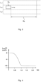
- Fig. 1 schematically illustrates a situation in which a vehicle V 0 comprising a vehicle trajectory control system 40 and an adaptive cruise control (ACC) system 10 is driving on a road.
- the vehicle trajectory control system 40 is configured for controlling an acceleration a 0 and a velocity v 0 of the vehicle V 0 and can comprise, for example, the motor, the transmission system and the braking system of the vehicle V 0 .
- the vehicle trajectory control system 40 is operatively connected with the ACC system 10 and can adjust the acceleration and the velocity of the vehicle V 0 based on a control instruction received from the ACC system 10.
- a preceding vehicle V 1 is driving in the same direction as the vehicle V 0 with a velocity ⁇ 1 .
- the distance d 1 is measured between the front bumper of the vehicle V 0 and the rear bumper of the preceding vehicle V 1 .
- Fig. 2 shows a schematic view of the components of the ACC system 10 of the vehicle V 0 .
- the ACC system 10 comprises a detection module 12, a safety module 14, a distance control module 20, a selection module 22 and a velocity control module 24.
- Each of the safety module 14, the distance control module 20 and the velocity control module 24 are connected with the detection module 12.
- the safety module 14 and the distance control module 20 are connected with the selection module 22.
- the safety module 14 comprises a nominal control unit 16, an emergency control unit 18 and an ICS control unit 17.
- the ACC system 10 comprises a connection port, by which the ACC system 10, in particular the selection module 22 and the velocity control module 24, are connected with the vehicle trajectory control system 40 in order to provide control instructions to the vehicle trajectory control system 40.
- Each of the modules 12, 14, 20, 22, 24 and 40 and each of the control units 16, 17 and 18 can be corresponding modules of a software product that are executed by one or more processors, but they can also correspond to one or more independent processors.
- each of the modules 12, 14, 20, 22, 24 and 40 and each of the control units 16, 17 and 18 can be an independent processor.
- the modules 12, 14, 20, 22, 24 and the control units 16, 17 and 18 can correspond to one processor while the system 40 corresponds to another processor.
- the detection module 12 comprises a system of radar sensor devices mounted at the front of the vehicle V 0 that are configured for detecting the preceding vehicle V 1 (and any other preceding vehicle driving ahead of the vehicle V 0 ) and for measuring, for each preceding vehicle, a corresponding distance with respect to the vehicle V 0 , such as the distance d 1 in Fig. 1 , and a corresponding velocity with respect to the vehicle, such as velocity ⁇ 1 in Fig. 1 .
- the detection module 12 can detect and measure the distance and velocity of any preceding vehicle driving ahead of the vehicle V 0 within a detection range distance d dr , which is the maximum distance from the vehicle V 0 , at which a preceding vehicle can be detected by the detection module 12.
- the vehicle V 0 is driving on the middle lane L 2 of a three-lane road having three lanes L 1 , L 2 , and L 3 , with no preceding vehicle driving ahead of the vehicle V 0 within the detection range distance d dr .
- no preceding vehicle is detected by the detection module 12 and the velocity control module 24 is activated by the detection module 12.
- the velocity control module 24 determines a target velocity ⁇ target of the vehicle V 0 , which is transmitted to the vehicle trajectory control system 40 being implemented as the velocity of the vehicle V 0 .
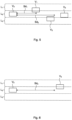
- Fig. 4 shows an exemplary braking jerk profile j brake (t).
- the braking jerk profile j brake (t) is a predefined function that is stored in a storage device (not shown) comprised in the ACC system to which the velocity control module 24 is connected.
- the predefined braking jerk profile j brake (t) is designed for providing a comfortable deceleration of the vehicle V 0 .
- the velocity control module 24 hence limits the velocity of the vehicle V 0 such that, if a standing preceding vehicle having a zero velocity were to appear suddenly within the detection range distance d dr , the vehicle V 0 , even if currently accelerating at the maximal possible acceleration, could brake according to the corresponding predefined braking jerk profile and come to a zero velocity state over the detection range distance d dr without colliding with such standing preceding vehicle.
- the safety module 14, the distance control module 20 and the selection module 22 can remain deactivated.
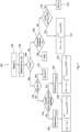
- Fig. 5 schematically illustrates a further exemplary situation on the same three lane road shown in Fig. 3 , but in which three preceding vehicles V 1 , V 2 , and V 3 are driving ahead of the vehicle V 0 .
- the preceding vehicle V 3 is driving entirely within the same lane L 2 as the vehicle V 0 .
- the preceding vehicle V 1 is moving laterally and changing lane from lane L 2 to lane L 1 , i.e. exiting the lane L2, but still being partly within it.
- the preceding vehicle V 2 is moving laterally and changing lane from lane L 3 to lane L 2 , i.e. entering the lane L 2 , but still being partly within lane L 3 .
- the detection module 12 is however configured for detecting not only the preceding vehicle V 3 , but also each of the preceding vehicles V 1 and V 2 as preceding vehicles.
- Fig. 6 schematically illustrates a further exemplary situation in which a preceding vehicle V 4 is driving ahead of the vehicle V 0 , changing from the lane L 1 into the lane L 2 , on which the vehicle V 0 is driving.
- Fig. 5 and 6 illustrate different possible situations, which may coexist.
- the situations illustrated in Fig. 5 and 6 coexist and all four preceding vehicles V 1 , V 2 , V 3 and V 4 are driving in front of the vehicle V 0 and are detected by the detection module 12.
- the ACC system 10 determines a target acceleration a target of the vehicle V 0 by determining, for each of the preceding vehicles V 1 , V 2 , V 3 and V 4 a candidate target acceleration according to a method 200 that is schematically illustrated in Figs. 7 and 9 .
- the ACC system executes, at 202 i , the method 100 i illustrated in Fig. 7 , which starts by detecting, at 102 i , each of the preceding vehicles V 1 , V 2 , V 3 and V 4 by the detection module 12, any by determining, at 104 i , the corresponding distance and velocity d;, ⁇ i , namely (d 1 , ⁇ 1 ), (d 2 , ⁇ 2 ), (d 3 , ⁇ 3 ) and (d 4 , ⁇ 4 ), respectively, for example by direct measurement using the radar sensor devices of the detection module 12.
- the detection module 12 determines in each case the corresponding safety distance sd; as the distance from the vehicle V 0 over which the vehicle V 0 can stop according to the predefined braking jerk profile j brake (t) without a collision with the corresponding preceding vehicle V i in case of a full braking of the corresponding preceding vehicle V i from a state of maximal acceleration of the vehicle V 0 .
- the preceding vehicles V 1 and V 2 are at a distance d 1 , d 2 from the vehicle V 0 smaller than a respective safety distance sd 1 and sd 2 , respectively, while the preceding vehicles V 3 and V 4 are at a respective distance d 3 , d 4 from the vehicle V 0 greater than the corresponding safety distance sd 3 and sd 4 .
- the detection module 12 compares, for each preceding vehicle V i , the computed safety distance sd i to the respective determined distance d; and, based thereon, activates the safety module 14 or the distance control module 20 for determining a corresponding candidate target acceleration cta;.
- the method 100 i proceeds to 108 i , where it is checked whether any of the preceding vehicles V 3 and V 4 fulfils an exclusion condition.
- the exclusion condition is fulfilled for a preceding vehicle V; if
- the method 100 3 (i.e. the method 100 i when carried out for determining the candidate target acceleration for the preceding vehicle V 3 ) ends after 108 3 and returns no candidate target acceleration (cf. "END" in Fig. 7 ).
- the method continues to 110 i with the activation of the distance control module 20 for determining the candidate target acceleration cta;.
- the distance control module 20 solves the equation of motion of the vehicle V 0 and the preceding vehicle V 4 taking into account the velocity and acceleration of the vehicle V 0 , the determined velocity ⁇ 4 of the preceding vehicle V 4 and the determined distance d 4 between the vehicle V 0 and the preceding vehicle V 4 and determines whether the respective safety distance sd 4 will be violated during the next iteration, i.e. during the coming predefined time interval ⁇ t from a current time t now assuming that the velocities of the vehicle V 0 and the preceding vehicle V 4 remain unchanged.
- the candidate target acceleration cta 4 is determined, at 114i, according to the predefined braking jerk profile j brake (t) shown in Fig. 4 . Otherwise, cta 4 is determined, at 112 i , to correspond to the current acceleration a 0 of the vehicle, such that the trajectory of the vehicle V 0 is left unaffected.
- the safety module 14 is activated for determining the corresponding candidate target accelerations.
- the corresponding candidate target acceleration cta is determined to correspond to the minimal possible acceleration a 0 min of the vehicle V 0 , i.e. the candidate target acceleration is chosen to correspond to the vehicle V 0 initiating a full braking manoeuvre.
- the nominal control unit 16 determines, at 124 i , by solving the equations of motion of the vehicle V 0 and the corresponding preceding vehicle V i (e.g. V 1 or V 2 in this case), whether it is feasible to establish the corresponding safety distance sd i by modifying the acceleration a 0 of the vehicle V 0 according to a comfort acceleration modification scheme, e.g.
- the nominal control unit 16 determines at 124 i that it is feasible to establish the corresponding safety distance sd i by modifying the acceleration a 0 of the vehicle V 0 according to a comfort acceleration modification scheme, i.e. if the result of the test at 124 i is positive, the nominal control unit 16 determines, at 126 i , a comfort jerk profile j comfor t (t) configured for modifying the acceleration a 0 of the vehicle V 0 according to the comfort acceleration modification scheme with the minimal possible jerk and taking into account the corresponding distance d i and velocity ⁇ i determined for the corresponding preceding vehicle V i .
- the comfort jerk profile j comfort (t) is determined by determining solutions to the equations of motion of the vehicle V 0 and the corresponding preceding vehicle V; imposing the aforesaid boundary conditions defined by the comfort acceleration modification scheme and choosing, among all possible solutions, the solution j(t) for which the minimal value of the jerk of the vehicle j comfort min is maximal, i.e. for which j comfort min closest to zero, in order to maximise comfort.
- FIG. 8a An exemplary comfort jerk profile j comfort (t) is schematically illustrated in Fig. 8a . As seen in Fig. 8a , the jerk according to the comfort jerk profile j comfor t (t) does not fall below the predefined jerk lower limit j lim .
- the emergency jerk profile j emergency (t) is determined by determining solutions to the equations of motion of the vehicle V 0 and the corresponding preceding vehicle V; imposing the aforesaid boundary conditions defined by the emergency acceleration modification scheme and choosing, among all possible solutions, the solution j(t) for which the minimal value of the jerk of the vehicle j emergency min is maximal, i.e. for which j emergency min is closest to zero, in order to maximise comfort.
- FIG. 8b An exemplary emergency jerk profile j emergency (t) is schematically illustrated in Fig. 8b .
- the jerk according to the emergency jerk profile j emergency (t) does fall below the predefined jerk lower limit j lim , unlike the comfort jerk profile j comfort (t).
- the minimal jerk value of the comfort jerk profile j comfort min is greater than a minimal jerk value of the emergency jerk profile j emergency min (cf. Fig. 8a ).
- the acceleration of the vehicle V 0 can be more rapidly reduced according to the emergency jerk profile j emergency (t) than according to the comfort jerk profile j comfort (t) but causing to the occupants a lower degree of comfort.
- Fig. 9 schematically illustrates how the target acceleration a target is determined by the ACC system 10 by determining for each of the preceding vehicles V 1 , V 2 , V 3 and V 4 corresponding candidate target acceleration is.
- the method 100 i is carried out, sequentially or in parallel, for each of the preceding vehicles V 1 , V 2 , V 3 and V 4 at 202 1 to 202 4 , respectively.
- the corresponding method 100 i For each of the preceding vehicles V 1 , V 2 , V 3 and V 4 , the corresponding method 100 i produces, as an output, a corresponding candidate target acceleration cta;, depending on the relative situation of that particular preceding vehicle V i with respect to the vehicle V 0 .
- no ICS is determined for either of the preceding vehicles V 1 or V 2 .
- the nominal control unit 16 determines at 124 1 , according to the equations of motion of the vehicle V 0 and the preceding vehicle V 1 , that it is not feasible to establish the safety distance sd 1 within the predetermined time t c by modifying the acceleration a 0 of the vehicle V 0 without the jerk of the vehicle falling below the predefined jerk lower limit is j lim .
- the nominal control unit 16 determines at 124 2 , according to the equations of motion of the vehicle V 0 and the preceding vehicle V 2 , that it is feasible to establish the safety distance sd 2 within the predetermined time t c without the jerk of the vehicle falling below the predefined jerk lower limit is j lim by modifying the acceleration a 0 of the vehicle V 0 according to the comfort jerk profile j comfor t (t) determined at 126 2 for the preceding vehicle V 2 .
- the exclusion condition check at 108 3 is positive, for which no candidate target acceleration is determined (cf. 204 3 in Fig. 9 ).
- the outcomes of the methods 100 i carried out for each of the preceding vehicles V 1 , V 2 , V 3 and V 4 are determined (cf. 204 1 , 204 2 , 204 3 , 204 4 in Fig. 9 ) and transmitted to the selection module 22 at 206, which selects as the target acceleration a target the minimal candidate target acceleration, i.e. the smallest of values of cta 1 , cta 2 and cta 4 min(cta 1 , cta 2 , cta 4 ).
- the selection module 22 selects, at 206, cta 1 as the target acceleration a target .
- the vehicle reacts to the current traffic situation with respect to the preceding vehicles V 1 , V 2 , V 3 and V 4 with the best possible balance between safety and comfort.
- an ICS had been determined by the ICS control unit 17 for any of the preceding vehicles V 1 , V 2 , V 3 and V 4 at the corresponding 120 i , the respective cta; would have corresponded to the minimal possible acceleration of the vehicle a 0 min , for which the outcome of the selection at 206 would have delivered a 0 min as an output and the vehicle trajectory control system 40 would have initiated at 208 a full braking manoeuvre of the vehicle V 0 .
Landscapes
- Engineering & Computer Science (AREA)
- Automation & Control Theory (AREA)
- Transportation (AREA)
- Mechanical Engineering (AREA)
- Control Of Driving Devices And Active Controlling Of Vehicle (AREA)
- Traffic Control Systems (AREA)
Claims (15)
- Adaptives Geschwindigkeitsregelungssystem (ACC) für ein Fahrzeug (V0), das Folgendes umfasst:ein Detektionsmodul (12), das zum Detektieren eines oder mehrerer vorausfahrender Fahrzeuge (V1, ..., Vn), die vor dem Fahrzeug (V0) fahren, und zum Bestimmen einer jeweiligen Geschwindigkeit (v1, ..., vn) und eines jeweiligen Abstands (d1, ..., dn) jedes der detektierten vorausfahrenden Fahrzeuge in Bezug auf das Fahrzeug (V0) konfiguriert ist; wobei das Detektionsmodul (12) ferner dazu konfiguriert ist, zu bestimmen, ob jeder der bestimmten Abstände kleiner als ein jeweiliger Sicherheitsabstand ist; undein Sicherheitsmodul (14), das mit dem Detektionsmodul (12) verbunden ist, wobei das Sicherheitsmodul (14) dazu konfiguriert ist, für jedes vorausfahrende Fahrzeug von mindestens einem Teil des einen oder der mehreren detektierten vorausfahrenden Fahrzeuge, für die der bestimmte Abstand (d1, ..., dn) kleiner als der jeweilige Sicherheitsabstand (sd1, ..., sdn) ist, eine jeweilige Kandidatenzielbeschleunigung (cta1, ..., ctan) des Fahrzeugs (V0) zu bestimmen, dadurch gekennzeichnet, dass das Sicherheitsmodul (14) Folgendes umfasst:eine ICS-Steuereinheit (17), die dazu konfiguriert ist, zu bestimmen, ob sich das Fahrzeug (V0) in einem unvermeidlichen Kollisionszustand in Bezug auf das entsprechende vorausfahrende Fahrzeug (Vi) befindet oder befinden wird, wobei der unvermeidliche Kollisionszustand einem Zustand des Fahrzeugs (V0) entspricht, in dem eine Kollision mit dem entsprechenden vorausfahrenden Fahrzeug (Vi) ungeachtet einer Modifikation einer Beschleunigung des Fahrzeugs (V0) unvermeidlich ist; wobei die ICS-Steuereinheit (17) ferner dazu konfiguriert ist, die jeweilige Kandidatenzielbeschleunigung (ctai) zu bestimmen, die einer minimal möglichen Beschleunigung (a0min) des Fahrzeugs entspricht, wenn die ICS-Steuereinheit (17) bestimmt, dass sich das Fahrzeug in einem unvermeidlichen Kollisionszustand befindet; undeine Notfallsteuereinheit (18), die dazu konfiguriert ist, die Kandidatenzielbeschleunigung (ctai) zu bestimmen, wenn die ICS-Steuereinheit (17) bestimmt, dass sich das Fahrzeug nicht in einem unvermeidlichen Kollisionszustand in Bezug auf das entsprechende vorausfahrende Fahrzeug (Vi) befindet, gemäß einem Notfallbeschleunigungsmodifikationsschema, wobei das Notfallbeschleunigungsmodifikationsschema dazu definiert ist, den jeweiligen Sicherheitsabstand (sdi) innerhalb einer vordefinierten Zeit (tc) zu erreichen und/oder ohne dass die Beschleunigung des Fahrzeugs unter eine erste vordefinierte untere Beschleunigungsgrenze fällt.
- ACC-System nach Anspruch 1, wobei das Sicherheitsmodul (14) ferner Folgendes umfasst:eine Nennsteuereinheit (16), die dazu konfiguriert ist, zu bestimmen, wenn die ICS-Steuereinheit (17) bestimmt, dass sich das Fahrzeug nicht in einem unvermeidlichen Kollisionszustand in Bezug auf das entsprechende vorausfahrende Fahrzeug (Vi) befindet, ob der jeweilige Sicherheitsabstand (sdi) durch Modifizieren der Beschleunigung des Fahrzeugs (a0) gemäß einem Komfortbeschleunigungsmodifikationsschema erreicht werden kann, wobei das Komfortbeschleunigungsmodifikationsschema dazu definiert ist, den jeweiligen Sicherheitsabstand (sdi) innerhalb der vordefinierten Zeit (tc) zu erreichen und ohne dass eine Zeitableitung der Beschleunigung des Fahrzeugs unter eine vordefinierte untere Beschleunigungsableitungsgrenze fällt und/oder ohne dass eine Beschleunigung des Fahrzeugs unter eine zweite vordefinierte untere Beschleunigungsgrenze fällt, wobei sich das Komfortbeschleunigungsmodifikationsschema von dem Notfallbeschleunigungsmodifikationsschema unterscheidet, wobei die Nennsteuereinheit (16) ferner dazu konfiguriert ist, die jeweilige Kandidatenzielbeschleunigung (ctai) gemäß dem Komfortbeschleunigungsmodifikationsschema zu bestimmen, wenn die Nennsteuereinheit (16) bestimmt, dass der jeweilige Sicherheitsabstand (sdi) durch Modifizieren der Beschleunigung des Fahrzeugs gemäß dem Komfortbeschleunigungsmodifikationsschema erreicht werden kann; undwobei die Notfallsteuereinheit (18) ferner dazu konfiguriert ist, die Kandidatenzielbeschleunigung (ctai) gemäß dem Notfallbeschleunigungsmodifikationsschema zu bestimmen, wenn die Nennsteuereinheit (16) bestimmt, dass der jeweilige Sicherheitsabstand (sdi) nicht durch Modifizieren der Beschleunigung des Fahrzeugs gemäß dem Komfortbeschleunigungsmodifikationsschema erreicht werden kann, und die ICS-Steuereinheit (17) bestimmt, dass sich das Fahrzeug nicht in einem unvermeidlichen Kollisionszustand in Bezug auf das entsprechende vorausfahrende Fahrzeug (Vi) befindet;wobei die Nennsteuereinheit (16) vorzugsweise dazu konfiguriert ist, zu bestimmen, ob der jeweilige Sicherheitsabstand (sdi) gemäß dem Komfortbeschleunigungsmodifikationsschema unter der Annahme erreicht werden kann, dass sich das entsprechende vorausfahrende Fahrzeug (Vi) mit einer konstanten Geschwindigkeit bewegt, die der bestimmten jeweiligen Geschwindigkeit (vi) entspricht.
- ACC-System nach einem der vorhergehenden Ansprüche, wobei die Notfallsteuereinheit (18) ferner dazu konfiguriert ist, basierend auf dem jeweiligen Abstand (di) und der jeweiligen Geschwindigkeit (vi) Folgendes zu bestimmen:- ein Notfallruckprofil (jemergency(t)), das eine zeitliche Entwicklung der zeitlichen Ableitung der Beschleunigung des Fahrzeugs definiert, die es ermöglicht, den jeweiligen Sicherheitsabstand (sdi) innerhalb der vordefinierten Zeit (tc) zu erreichen und/oder ohne dass die Beschleunigung des Fahrzeugs unter die erste vordefinierte untere Beschleunigungsgrenze fällt; und/oder- ein Notfallbeschleunigungsprofil (aemergency(t)), das eine zeitliche Entwicklung der Beschleunigung des Fahrzeugs definiert, die es ermöglicht, den jeweiligen Sicherheitsabstand (sdi) innerhalb der vordefinierten Zeit (tc) zu erreichen und/oder ohne dass die Beschleunigung des Fahrzeugs unter die erste vordefinierte untere Beschleunigungsgrenze fällt; undwobei die Notfallsteuereinheit (18) dazu konfiguriert ist, die jeweilige Kandidatenzielbeschleunigung (ctai) gemäß dem Notfallruckprofil (jemergency(t)) und/oder dem Notfallbeschleunigungsprofil (aemergency(t)) zu bestimmen.
- ACC-System nach einem der Ansprüche 2 oder 3, wobei die Nennsteuereinheit (16) ferner dazu konfiguriert ist, wenn die Nennsteuereinheit (16) bestimmt, dass der jeweilige Sicherheitsabstand (sdi) durch Modifizieren der Beschleunigung des Fahrzeugs gemäß dem Komfortbeschleunigungsmodifikationsschema erreicht werden kann, basierend auf dem jeweiligen Abstand (di) und der jeweiligen Geschwindigkeit (vi), die für das entsprechende vorausfahrende Fahrzeug (Vi) bestimmt wurden, Folgendes zu bestimmen:- ein Komfortruckprofil (jcomfort(t)), das eine zeitliche Entwicklung der zeitlichen Ableitung der Beschleunigung des Fahrzeugs definiert, die es ermöglicht, den jeweiligen Sicherheitsabstand (sdi) innerhalb der vordefinierten Zeit (tc) zu erreichen, ohne dass eine zeitliche Ableitung der Beschleunigung des Fahrzeugs unter die vordefinierte untere Beschleunigungsableitungsgrenze fällt und/oder ohne dass die Beschleunigung des Fahrzeugs unter die zweite untere Beschleunigungsgrenze fällt; und/oder- ein Komfortbeschleunigungsprofil (acomfort(t)), das eine zeitliche Entwicklung der Beschleunigung des Fahrzeugs definiert, die es ermöglicht, den jeweiligen Sicherheitsabstand (sdi) innerhalb der vordefinierten Zeit (tc) zu erreichen, ohne dass eine zeitliche Ableitung der Beschleunigung des Fahrzeugs unter die vordefinierte untere Beschleunigungsableitungsgrenze fällt und/oder ohne dass die Beschleunigung des Fahrzeugs unter die zweite untere Beschleunigungsgrenze fällt; undwobei die Nominalsteuereinheit (16) dazu konfiguriert ist, die jeweilige Kandidatenzielbeschleunigung (ctai) gemäß dem Komfortruckprofil (jcomfort(t)) und/oder dem Komfortbeschleunigungsprofil (acomfort(t)) zu bestimmen.
- ACC-System nach Anspruch 3 und 4, wobei die Notfallsteuereinheit (18) dazu konfiguriert ist, das Notfallruckprofil (jemergency(t)) und/oder das Notfallbeschleunigungsprofil (aemergency(t)) zu bestimmen, wenn die Nominalsteuereinheit (16) bestimmt, dass der jeweilige Sicherheitsabstand (sdi) nicht durch Modifizieren der Beschleunigung des Fahrzeugs gemäß dem Komfortbeschleunigungsmodifikationsschema erreicht werden kann, und/oder wenn die ICS-Steuereinheit (17) bestimmt, dass sich das Fahrzeug nicht in einem unvermeidlichen Kollisionszustand in Bezug auf das entsprechende vorausfahrende Fahrzeug (Vi) befindet.
- ACC-System nach einem der Ansprüche 2 bis 5, wobei das Bestimmen der jeweiligen Kandidatenzielbeschleunigung (ctai) gemäß dem Komfortbeschleunigungsmodifikationsschema durch die Nominalsteuereinheit (16) das Bestimmen der jeweiligen Kandidatenbeschleunigung (ctai) als einen ersten Beschleunigungswert (a1) umfasst; undwobei das Bestimmen der jeweiligen Kandidatenzielbeschleunigung (ctai) gemäß dem Notfallbeschleunigungsmodifikationsschema durch die Notfallsteuereinheit (18) das Bestimmen der jeweiligen Kandidatenbeschleunigung (ctai) als einen zweiten Beschleunigungswert (a2) umfasst;wobei der erste Beschleunigungswert (a1) größer als der zweite Beschleunigungswert (a2) ist; und/oderwobei ein Minimalwert der Beschleunigung des Fahrzeugs oder der zeitlichen Ableitung davon gemäß dem Komfortbeschleunigungsmodifikationsschema größer als ein Minimalwert der Beschleunigung des Fahrzeugs oder der zeitlichen Ableitung davon gemäß dem Notfallbeschleunigungsmodifikationsschema ist.
- ACC-System nach einem der vorhergehenden Ansprüche, ferner umfassend ein Abstandssteuermodul (20), das mit dem Detektionsmodul (12) verbunden und dazu konfiguriert ist, für jedes von mindestens einem Teil des einen oder der mehreren vorausfahrenden Fahrzeuge (V1, ..., Vn), für die der bestimmte jeweilige Abstand (d1, ..., dn) gleich dem jeweiligen Sicherheitsabstand (sd1, ..., sdn) ist oder diesen überschreitet, zu bestimmen, ob sich das Fahrzeug (Vo) in einem potentiellen Kollisionszustand in Bezug auf das entsprechende vorausfahrende Fahrzeug (Vi) befindet, wobei der potentielle Kollisionszustand einem Zustand des Fahrzeugs (Vo) entspricht, in dem, wenn das entsprechende vorausfahrende Fahrzeug (Vi) ein vollständiges Bremsmanöver einleitet, ein Abstand zwischen dem Fahrzeug und dem entsprechenden vorausfahrenden Fahrzeug innerhalb eines vordefinierten Zeitintervalls (Δt) kleiner als der jeweilige Sicherheitsabstand (sdi) wird, es sei denn, die Beschleunigung des Fahrzeugs wird modifiziert;
wobei, wenn das Abstandssteuermodul (20) bestimmt, dass sich das Fahrzeug (Vo) in einem potentiellen Kollisionszustand in Bezug auf das entsprechende vorausfahrende Fahrzeug (Vi) befindet, das Abstandssteuermodul (20) ferner zu Folgendem konfiguriert ist:
Bestimmen der entsprechenden Kandidatenzielbeschleunigung (ctai) gemäß einem vorbestimmten Abstandssteuerbeschleunigungsmodifikationsschema. - ACC-System nach einem der vorhergehenden Ansprüche, wobei der mindestens eine Teil des einen oder der mehreren detektierten vorausfahrenden Fahrzeuge (V1, ..., Vn), für die der bestimmte Abstand (d1, ..., dn) kleiner als der jeweilige Sicherheitsabstand (sd1, ..., sdn) ist, und/oder der mindestens eine Teil des einen oder der mehreren vorausfahrenden Fahrzeuge (V1, ..., Vn), für die der bestimmte Abstand (d1, ..., dn) gleich dem jeweiligen Sicherheitsabstand (sd1, ..., sdn) ist oder diesen überschreitet, vorausfahrende Fahrzeuge umfasst, für die eine Ausschlussbedingung nicht erfüllt ist, wobei die Ausschlussbedingung für ein gegebenes vorausfahrendes Fahrzeug (Vi) erfüllt ist, wenn- ein anderes vorausfahrendes Fahrzeug (Vj) existiert, für das der bestimmte Abstand (d;) und die bestimmte Geschwindigkeit (vj) jeweils kleiner als der Abstand (di) und die Geschwindigkeit (vi) sind, die für das gegebene vorausfahrende Fahrzeug (Vi) bestimmt wurden; und/oder- eine Differenz zwischen dem für das gegebene vorausfahrende Fahrzeug (di) bestimmten Abstand und einem Anhalteabstand (dstop) des Fahrzeugs (Vo) gleich oder größer als null oder ein Sicherheitsabstand ist, wobei der Anhalteabstand (dstop) des Fahrzeugs (Vo) einem Mindestabstand entspricht, der vom Fahrzeug zurückgelegt wird, bis das Fahrzeug in einen Nullgeschwindigkeitszustand kommt, insbesondere gemäß einem vordefinierten Bremsbeschleunigungsmodifikationsschema; und/oderferner umfassend ein Auswahlmodul (22), das dazu konfiguriert ist, unter allen Kandidatenzielbeschleunigungen (cta1, ..., ctan), die durch das Sicherheitsmodul (14) oder das Abstandssteuermodul (20) bestimmt wurden, eine minimale Kandidatenzielbeschleunigung (ctamin) auszuwählen, wobei die minimale Kandidatenzielbeschleunigung kleiner als alle anderen Kandidatenzielbeschleunigungen ist.
- Fahrzeug (Vo), das Folgendes umfasst:ein Fahrzeugtrajektoriensteuersystem (40), das dazu konfiguriert ist, eine Beschleunigung und/oder eine Geschwindigkeit des Fahrzeugs (Vo) zu steuern; und ein adaptives Geschwindigkeitsregelungssystem (ACC) (10) nach einem der vorhergehenden Ansprüche,wobei das Fahrzeugtrajektoriensteuersystem (40) dazu konfiguriert ist, die Beschleunigung und/oder die Geschwindigkeit des Fahrzeugs (Vo) gemäß einer Zielgeschwindigkeit (vtarget) und/oder einer Kandidatenzielbeschleunigung (ctai), die durch das ACC-System (10) bestimmt wurde, vorzugsweise gemäß einer minimalen Kandidatenzielbeschleunigung (ctamin), die unter mehreren Kandidatenzielbeschleunigungen (cta1, ..., ctan) ausgewählt wurde, die für entsprechende mehrere erkannte vorausfahrende Fahrzeuge bestimmt wurden, zu steuern.
- Verfahren (200) zum Bestimmen einer Zielbeschleunigung (atarget) eines Fahrzeugs (Vo), wobei das Verfahren Folgendes umfasst:Detektieren (102i) eines oder mehrerer vorausfahrender Fahrzeuge (V1, ..., Vn), die vor dem Fahrzeug (Vo) fahren;Bestimmen (104i) einer Geschwindigkeit (v1, ..., vn) und eines Abstands (d1, ..., dn) jedes des einen oder der mehreren detektierten vorausfahrenden Fahrzeuge (V1, ..., Vn) in Bezug auf das Fahrzeug (Vo); undBestimmen der Zielbeschleunigung (atarget) durch Bestimmen (204i) für jedes vorausfahrende Fahrzeug von mindestens einem Teil des einen oder der mehreren detektierten vorausfahrenden Fahrzeuge (V1, ..., Vn) einer jeweiligen Kandidatenzielbeschleunigung (ctai) des Fahrzeugs (Vo) und durch Auswählen (206) der minimalen Kandidatenzielbeschleunigung (ctamin) als die Zielbeschleunigung (atarget), dadurch gekennzeichnet, dass das Bestimmen der entsprechenden Kandidatenzielbeschleunigung (ctai) für ein entsprechendes vorausfahrendes Fahrzeug (Vi) in jedem Fall Folgendes umfasst:
Bestimmen (106i), ob der entsprechende bestimmte Abstand (di) kleiner als ein jeweiliger Sicherheitsabstand (sdi) ist, und wenn der entsprechende bestimmte Abstand (di) kleiner als der jeweilige Sicherheitsabstand (sdi) ist:Bestimmen (120i), ob sich das Fahrzeug (Vo) in einem unvermeidlichen Kollisionszustand in Bezug auf das entsprechende vorausfahrende Fahrzeug (Vi) befindet oder befinden wird, wobei der unvermeidliche Kollisionszustand einem Zustand des Fahrzeugs (Vo) entspricht, in dem eine Kollision mit dem entsprechenden vorausfahrenden Fahrzeug (Vi) ungeachtet einer Modifikation der Beschleunigung des Fahrzeugs (Vo) unvermeidlich ist, und wenn sich das Fahrzeug (Vo) in einem unvermeidlichen Kollisionszustand in Bezug auf das entsprechende vorausfahrende Fahrzeug (Vi) befindet, Bestimmen der entsprechenden Kandidatenzielbeschleunigung (ctai) als eine minimal mögliche Beschleunigung (aomin) des Fahrzeugs; undwenn sich das Fahrzeug (Vo) nicht in einem unvermeidlichen Kollisionszustand in Bezug auf das entsprechende vorausfahrende Fahrzeug (Vi) befindet, Bestimmen (132i) der entsprechenden Kandidatenzielbeschleunigung (ctai) gemäß einem Notfallbeschleunigungsmodifikationsschema, wobei das Notfallbeschleunigungsmodifikationsschema dazu definiert ist, den jeweiligen Sicherheitsabstand (sdi) innerhalb einer vordefinierten Zeit (tc) zu erreichen und/oder ohne dass die Beschleunigung des Fahrzeugs unter eine erste vordefinierte untere Beschleunigungsgrenze fällt. - Verfahren nach Anspruch 10, wobei, wenn der entsprechende bestimmte Abstand (di) kleiner als der jeweilige Sicherheitsabstand (sdi) ist und sich das Fahrzeug (Vo) nicht in einem unvermeidlichen Kollisionszustand in Bezug auf das entsprechende vorausfahrende Fahrzeug (Vi) befindet, das Bestimmen der entsprechenden Kandidatenzielbeschleunigung (ctai) für ein entsprechendes vorausfahrendes Fahrzeug (Vi) ferner Folgendes umfasst:Bestimmen (124i), ob es möglich ist, den jeweiligen Sicherheitsabstand (sdi) zu erreichen, indem die Beschleunigung des Fahrzeugs (Vo) gemäß einem Komfortbeschleunigungsmodifikationsschema modifiziert wird, wobei das Komfortbeschleunigungsmodifikationsschema dazu definiert ist, den jeweiligen Sicherheitsabstand (sdi) innerhalb einer vordefinierten Zeit (tc) zu erreichen und/oder ohne dass eine zeitliche Ableitung der Beschleunigung des Fahrzeugs unter eine vordefinierte untere Beschleunigungsableitungsgrenze (jlim) fällt und/oder ohne dass eine Beschleunigung des Fahrzeugs unter eine zweite vordefinierte untere Beschleunigungsgrenze fällt, undwenn es möglich ist, den jeweiligen Sicherheitsabstand (sdi) gemäß dem Komfortbeschleunigungsmodifikationsschema zu erreichen, Bestimmen (128i) der entsprechenden Kandidatenzielbeschleunigung (ctai) gemäß dem Komfortbeschleunigungsmodifikationsschema; und wobei die entsprechende Kandidatenzielbeschleunigung (ctai) gemäß dem Notfallbeschleunigungsmodifikationsschema bestimmt wird, wenn sich das Fahrzeug (Vo) nicht in einem unvermeidlichen Kollisionszustand in Bezug auf das entsprechende vorausfahrende Fahrzeug (Vi) befindet und es nicht möglich ist, den jeweiligen Sicherheitsabstand (sdi) gemäß dem Komfortbeschleunigungsmodifikationsschema zu erreichen, wobei das Bestimmen (124i), ob es möglich ist, den jeweiligen Sicherheitsabstand (sdi) zu erreichen, durch Modifizieren der Beschleunigung des Fahrzeugs gemäß dem Komfortbeschleunigungsmodifikationsschema vorzugsweise das Annehmen umfasst, dass sich das entsprechende vorausfahrende Fahrzeug (Vi) mit einer konstanten Geschwindigkeit bewegt, die der bestimmten jeweiligen Geschwindigkeit (vi) entspricht.
- Verfahren nach einem der Ansprüche 10 oder 11, wobei das Bestimmen der entsprechenden Kandidatenzielbeschleunigung (ctai) gemäß dem Notfallbeschleunigungsmodifikationsschema das Bestimmen (130i) basierend auf dem jeweiligen Abstand (di) und der jeweiligen Geschwindigkeit (vi), die für das entsprechende vorausfahrende Fahrzeug (Vi) bestimmt wurden, umfasst- ein Notfallruckprofil (jemergency(t)), das eine zeitliche Entwicklung der zeitlichen Ableitung der Beschleunigung des Fahrzeugs definiert, die es ermöglicht, den jeweiligen Sicherheitsabstand (sdi) innerhalb der vordefinierten Zeit (tc) zu erreichen und/oder ohne dass die Beschleunigung des Fahrzeugs unter die erste vordefinierte untere Beschleunigungsgrenze fällt; und/oder- ein Notfallbeschleunigungsprofil (aemergency(t)), das eine zeitliche Entwicklung der Beschleunigung des Fahrzeugs definiert, die es ermöglicht, den jeweiligen Sicherheitsabstand (sdi) innerhalb der vordefinierten Zeit (tc) zu erreichen und/oder ohne dass die Beschleunigung des Fahrzeugs unter die erste vordefinierte untere Beschleunigungsgrenze fällt; undwobei die jeweilige Kandidatenzielbeschleunigung (ctai) für das entsprechende vorausfahrende Fahrzeug (Vi) gemäß dem Notfallruckprofil (jemergency(t)) und/oder dem Notfallbeschleunigungsprofil (aemergency(t)) bestimmt wird.
- Verfahren nach einem der Ansprüche 11 oder 12, wobei das Bestimmen der entsprechenden Kandidatenzielbeschleunigung (ctai) gemäß dem Komfortbeschleunigungsmodifikationsschema das Bestimmen (126i) basierend auf dem jeweiligen Abstand (di) und der jeweiligen Geschwindigkeit (vi), die für das entsprechende vorausfahrende Fahrzeug (Vi) bestimmt wurden, umfasst:- ein Komfortruckprofil (jcomfort(t)), das eine zeitliche Entwicklung der zeitlichen Ableitung der Beschleunigung des Fahrzeugs definiert, die es ermöglicht, den jeweiligen Sicherheitsabstand (sdi) innerhalb der vordefinierten Zeit (tc) zu erreichen, ohne dass eine zeitliche Ableitung der Beschleunigung des Fahrzeugs unter die vordefinierte untere Beschleunigungsableitungsgrenze fällt und/oder ohne dass die Beschleunigung des Fahrzeugs unter die zweite untere Beschleunigungsgrenze fällt; und/oder- ein Komfortbeschleunigungsprofil (acomfort(t)), das eine zeitliche Entwicklung der Beschleunigung des Fahrzeugs definiert, die es ermöglicht, den jeweiligen Sicherheitsabstand (sdi) innerhalb der vordefinierten Zeit (tc) zu erreichen, ohne dass eine zeitliche Ableitung der Beschleunigung des Fahrzeugs unter die vordefinierte untere Beschleunigungsableitungsgrenze fällt und/oder ohne dass die Beschleunigung des Fahrzeugs unter die zweite untere Beschleunigungsgrenze fällt; undwobei die jeweilige Kandidatenzielbeschleunigung (ctai) für das entsprechende vorausfahrende Fahrzeug (Vi) gemäß dem Komfortruckprofil (jcomfort(t)) und/oder dem Komfortbeschleunigungsprofil (acomfort(t)) bestimmt wird.
- Verfahren nach den Ansprüchen 12 und 13, wobei das Notfallruckprofil (jemergency(t)) und/oder das Notfallbeschleunigungsprofil (aemergency(t)) bestimmt wird, wenn der jeweilige Sicherheitsabstand (sdi) nicht durch Modifizieren der Beschleunigung des Fahrzeugs gemäß dem Komfortbeschleunigungsmodifikationsschema erreicht werden kann und/oder wenn sich das Fahrzeug (Vo) nicht in einem unvermeidlichen Kollisionszustand in Bezug auf das entsprechende vorausfahrende Fahrzeug (Vi) befindet.
- Verfahren nach einem der Ansprüche 11 bis 14, wobei das Bestimmen der entsprechenden Kandidatenzielbeschleunigung (ctai) eines entsprechenden vorausfahrenden Fahrzeugs (Vi) ferner, wenn der entsprechende bestimmte Abstand (di) gleich dem jeweiligen Sicherheitsabstand (sdi) ist oder diesen überschreitet, das Bestimmen (110i) umfasst, ob sich das Fahrzeug (Vo) in einem potentiellen Kollisionszustand in Bezug auf das entsprechende vorausfahrende Fahrzeug (Vi) befindet, wobei der potentielle Kollisionszustand einem Zustand des Fahrzeugs (Vo) entspricht, in dem, wenn das entsprechende vorausfahrende Fahrzeug (Vi) ein vollständiges Bremsmanöver einleitet, ein Abstand zwischen dem Fahrzeug (Vo) und dem entsprechenden vorausfahrenden Fahrzeug (Vi) innerhalb eines vordefinierten Zeitintervalls (Δt) kleiner als der jeweilige Sicherheitsabstand (sdi) wird, es sei denn, die Beschleunigung des Fahrzeugs (Vo) wird modifiziert; und
wenn sich das Fahrzeug (Vo) in einem potentiellen Kollisionszustand in Bezug auf das entsprechende vorausfahrende Fahrzeug (Vi) befindet, Bestimmen (114i) der entsprechenden Kandidatenzielbeschleunigung (ctai) gemäß einem vorbestimmten Abstandssteuerbeschleunigungsmodifikationsschema.
Applications Claiming Priority (4)
| Application Number | Priority Date | Filing Date | Title |
|---|---|---|---|
| EP20169720 | 2020-04-15 | ||
| EP20169992 | 2020-04-16 | ||
| EP20172447.3A EP3895948A1 (de) | 2020-04-15 | 2020-04-30 | Einschersicheres adaptives geschwindigkeitsregelsystem für fahrzeuge |
| PCT/EP2021/056304 WO2021209202A1 (en) | 2020-04-15 | 2021-03-12 | Cut-in-safe adaptive cruise control system for vehicles |
Publications (3)
| Publication Number | Publication Date |
|---|---|
| EP4136003A1 EP4136003A1 (de) | 2023-02-22 |
| EP4136003B1 true EP4136003B1 (de) | 2024-01-10 |
| EP4136003C0 EP4136003C0 (de) | 2024-01-10 |
Family
ID=70482412
Family Applications (2)
| Application Number | Title | Priority Date | Filing Date |
|---|---|---|---|
| EP20172447.3A Withdrawn EP3895948A1 (de) | 2020-04-15 | 2020-04-30 | Einschersicheres adaptives geschwindigkeitsregelsystem für fahrzeuge |
| EP21710970.1A Active EP4136003B1 (de) | 2020-04-15 | 2021-03-12 | Einschersicheres adaptives geschwindigkeitsregelsystem für fahrzeuge |
Family Applications Before (1)
| Application Number | Title | Priority Date | Filing Date |
|---|---|---|---|
| EP20172447.3A Withdrawn EP3895948A1 (de) | 2020-04-15 | 2020-04-30 | Einschersicheres adaptives geschwindigkeitsregelsystem für fahrzeuge |
Country Status (4)
| Country | Link |
|---|---|
| US (1) | US20230339465A1 (de) |
| EP (2) | EP3895948A1 (de) |
| CN (1) | CN115362091A (de) |
| WO (1) | WO2021209202A1 (de) |
Families Citing this family (12)
| Publication number | Priority date | Publication date | Assignee | Title |
|---|---|---|---|---|
| GB201916026D0 (en) * | 2019-11-04 | 2019-12-18 | Five Ai Ltd | Adaptive cruise control |
| JP7364111B2 (ja) * | 2021-02-25 | 2023-10-18 | 株式会社デンソー | 処理方法、処理システム、処理プログラム |
| GB202103435D0 (en) * | 2021-03-12 | 2021-04-28 | Five Ai Ltd | Implementing slowdown manoeuvres in autonomous vehicles |
| FR3122856A1 (fr) * | 2021-05-11 | 2022-11-18 | Renault S.A.S. | Procédé de gestion de la vitesse longitudinale d’un véhicule autonome. |
| CN115871662A (zh) * | 2021-09-26 | 2023-03-31 | 本田技研工业株式会社 | 车辆控制装置以及方法 |
| JP7700753B2 (ja) * | 2022-08-04 | 2025-07-01 | トヨタ自動車株式会社 | 車両 |
| CN115465273B (zh) * | 2022-10-18 | 2023-06-16 | 上海洛轲智能科技有限公司 | 跟车状态调整方法、装置、设备及计算机存储介质 |
| WO2024082590A1 (zh) * | 2022-10-18 | 2024-04-25 | 上海洛轲智能科技有限公司 | 调整跟车状态的预测时间确定方法、装置及设备 |
| CN115556749B (zh) * | 2022-10-18 | 2024-03-19 | 上海洛轲智能科技有限公司 | 调整跟车状态的预测时间确定方法、装置及设备 |
| US20240166209A1 (en) * | 2022-11-22 | 2024-05-23 | Toyota Motor Engineering & Manufacturing North America, Inc. | System and method for controlling a cruise control system of a vehicle using the moods of one or more occupants |
| DE102022212567A1 (de) * | 2022-11-24 | 2024-05-29 | Robert Bosch Gesellschaft mit beschränkter Haftung | Verfahren zur Kontrolle eines Spurwechsels eines Fahrzeuges |
| CN116767241A (zh) * | 2023-06-27 | 2023-09-19 | 联创汽车电子有限公司 | 自车期望加速度修正方法、系统及存储介质 |
Family Cites Families (12)
| Publication number | Priority date | Publication date | Assignee | Title |
|---|---|---|---|---|
| JP3681052B2 (ja) * | 2000-01-11 | 2005-08-10 | 三菱電機株式会社 | 追従走行制御装置 |
| DE10392862D2 (de) * | 2002-07-05 | 2005-09-15 | Continental Teves Ag & Co Ohg | Fahrerassistenzsystem und Vorrichtung zur Bremsenregelung |
| DE10356309A1 (de) * | 2003-11-28 | 2005-06-23 | Robert Bosch Gmbh | Verfahren und Vorrichtung zur Warnung des Fahrers eines Kraftfahrzeugs |
| DE102006033145A1 (de) * | 2006-07-18 | 2008-01-24 | Robert Bosch Gmbh | Verfahren und Vorrichtung zur Vermeidung und/oder Minderung der Folgen von Kollisionen |
| JP2009120116A (ja) * | 2007-11-16 | 2009-06-04 | Hitachi Ltd | 車両衝突回避支援装置 |
| JP5929885B2 (ja) * | 2013-12-20 | 2016-06-08 | 株式会社デンソー | 車間制御装置 |
| JP6481520B2 (ja) * | 2015-06-05 | 2019-03-13 | トヨタ自動車株式会社 | 車両の衝突回避支援装置 |
| JP6269606B2 (ja) * | 2015-07-21 | 2018-01-31 | トヨタ自動車株式会社 | 車両制御装置 |
| EP3196089B1 (de) * | 2016-01-21 | 2021-10-13 | Volvo Car Corporation | Fahrzeugsicherheitsunterstützungssystem, fahrzeug mit einem fahrzeugsicherheitsunterstützungssystem und verfahren zur bereitstellung einer fahrerwarnung oder zur durchführung einer autonomen bremsung |
| JP6645649B2 (ja) * | 2016-02-17 | 2020-02-14 | 本田技研工業株式会社 | 車両制御装置、車両制御方法、および車両制御プログラム |
| JP6809331B2 (ja) * | 2017-03-28 | 2021-01-06 | トヨタ自動車株式会社 | 車両制御装置 |
| US11072326B2 (en) * | 2019-08-22 | 2021-07-27 | Argo AI, LLC | Systems and methods for trajectory based safekeeping of vehicles |
-
2020
- 2020-04-30 EP EP20172447.3A patent/EP3895948A1/de not_active Withdrawn
-
2021
- 2021-03-12 EP EP21710970.1A patent/EP4136003B1/de active Active
- 2021-03-12 CN CN202180026590.3A patent/CN115362091A/zh active Pending
- 2021-03-12 US US17/918,920 patent/US20230339465A1/en active Pending
- 2021-03-12 WO PCT/EP2021/056304 patent/WO2021209202A1/en not_active Ceased
Also Published As
| Publication number | Publication date |
|---|---|
| CN115362091A (zh) | 2022-11-18 |
| EP4136003C0 (de) | 2024-01-10 |
| WO2021209202A1 (en) | 2021-10-21 |
| EP4136003A1 (de) | 2023-02-22 |
| US20230339465A1 (en) | 2023-10-26 |
| EP3895948A1 (de) | 2021-10-20 |
Similar Documents
| Publication | Publication Date | Title |
|---|---|---|
| EP3895948A1 (de) | Einschersicheres adaptives geschwindigkeitsregelsystem für fahrzeuge | |
| EP1426230B1 (de) | Fahrassistenzsystem für ein Kraftfahrzeug | |
| US10996672B2 (en) | Driving control apparatus for vehicle | |
| US7565234B2 (en) | Automotive collision mitigation apparatus | |
| JP4167069B2 (ja) | 自動車追い越し動作支援方法,自動車追い越し動作支援装置 | |
| US7668633B2 (en) | Electronic control system for a vehicle and method for determining at least one driver-independent intervention in a vehicle system | |
| CN104960509B (zh) | 用于基于碰撞置信度最小化自动制动侵扰的方法 | |
| US9566959B2 (en) | Method for determining an emergency braking situation of a vehicle | |
| JP4967840B2 (ja) | 衝突軽減装置 | |
| EP3196089B1 (de) | Fahrzeugsicherheitsunterstützungssystem, fahrzeug mit einem fahrzeugsicherheitsunterstützungssystem und verfahren zur bereitstellung einer fahrerwarnung oder zur durchführung einer autonomen bremsung | |
| EP3707045B1 (de) | Warnung und regelung der längsgeschwindigkeit eines kraftfahrzeuges auf der basis der erkannten verkehrsampeln | |
| US8508351B2 (en) | Method for warning the driver of a motor vehicle of increased risk of an accident | |
| KR20150051548A (ko) | 운전자의 성향을 반영하는 운전보조시스템 및 그 제어방법 | |
| US7715275B2 (en) | Start assist system for motor vehicles | |
| EP3418152B1 (de) | Fahrzeugsteuerungsvorrichtung | |
| US12528514B2 (en) | Autonomous vehicle having a device which evaluates driving performance | |
| US20230347883A1 (en) | Method and arrangement to timely trigger automatic emergency braking operation and to control the longitudinal movement of a vehicle | |
| JP2023138401A (ja) | 自車両用支援システムおよび方法 | |
| CN116279341A (zh) | 安全刹车方法和装置、电子设备和存储介质 | |
| KR101511860B1 (ko) | 운전보조시스템 및 그 제어방법 | |
| JP2023553018A (ja) | 自動走行中の車両の作動方法 | |
| EP4015326A1 (de) | Fahrzeugsteuerungssystem, fahrzeug und verfahren | |
| CN116001788A (zh) | 跟车方法、电子设备、车辆及存储介质 | |
| KR20240169156A (ko) | 차량의 충돌 위험 판단 시스템 및 방법 | |
| WO2023172406A1 (en) | Systems and methods for vehicle signaling and bargaining |
Legal Events
| Date | Code | Title | Description |
|---|---|---|---|
| STAA | Information on the status of an ep patent application or granted ep patent |
Free format text: STATUS: UNKNOWN |
|
| STAA | Information on the status of an ep patent application or granted ep patent |
Free format text: STATUS: THE INTERNATIONAL PUBLICATION HAS BEEN MADE |
|
| PUAI | Public reference made under article 153(3) epc to a published international application that has entered the european phase |
Free format text: ORIGINAL CODE: 0009012 |
|
| STAA | Information on the status of an ep patent application or granted ep patent |
Free format text: STATUS: REQUEST FOR EXAMINATION WAS MADE |
|
| 17P | Request for examination filed |
Effective date: 20220921 |
|
| AK | Designated contracting states |
Kind code of ref document: A1 Designated state(s): AL AT BE BG CH CY CZ DE DK EE ES FI FR GB GR HR HU IE IS IT LI LT LU LV MC MK MT NL NO PL PT RO RS SE SI SK SM TR |
|
| DAV | Request for validation of the european patent (deleted) | ||
| DAX | Request for extension of the european patent (deleted) | ||
| GRAP | Despatch of communication of intention to grant a patent |
Free format text: ORIGINAL CODE: EPIDOSNIGR1 |
|
| STAA | Information on the status of an ep patent application or granted ep patent |
Free format text: STATUS: GRANT OF PATENT IS INTENDED |
|
| INTG | Intention to grant announced |
Effective date: 20230803 |
|
| GRAS | Grant fee paid |
Free format text: ORIGINAL CODE: EPIDOSNIGR3 |
|
| GRAA | (expected) grant |
Free format text: ORIGINAL CODE: 0009210 |
|
| STAA | Information on the status of an ep patent application or granted ep patent |
Free format text: STATUS: THE PATENT HAS BEEN GRANTED |
|
| AK | Designated contracting states |
Kind code of ref document: B1 Designated state(s): AL AT BE BG CH CY CZ DE DK EE ES FI FR GB GR HR HU IE IS IT LI LT LU LV MC MK MT NL NO PL PT RO RS SE SI SK SM TR |
|
| REG | Reference to a national code |
Ref country code: GB Ref legal event code: FG4D |
|
| REG | Reference to a national code |
Ref country code: CH Ref legal event code: EP |
|
| REG | Reference to a national code |
Ref country code: DE Ref legal event code: R096 Ref document number: 602021008540 Country of ref document: DE |
|
| REG | Reference to a national code |
Ref country code: IE Ref legal event code: FG4D |
|
| U01 | Request for unitary effect filed |
Effective date: 20240205 |
|
| U07 | Unitary effect registered |
Designated state(s): AT BE BG DE DK EE FI FR IT LT LU LV MT NL PT SE SI Effective date: 20240214 |
|
| U20 | Renewal fee for the european patent with unitary effect paid |
Year of fee payment: 4 Effective date: 20240221 |
|
| PG25 | Lapsed in a contracting state [announced via postgrant information from national office to epo] |
Ref country code: IS Free format text: LAPSE BECAUSE OF FAILURE TO SUBMIT A TRANSLATION OF THE DESCRIPTION OR TO PAY THE FEE WITHIN THE PRESCRIBED TIME-LIMIT Effective date: 20240510 |
|
| PG25 | Lapsed in a contracting state [announced via postgrant information from national office to epo] |
Ref country code: GR Free format text: LAPSE BECAUSE OF FAILURE TO SUBMIT A TRANSLATION OF THE DESCRIPTION OR TO PAY THE FEE WITHIN THE PRESCRIBED TIME-LIMIT Effective date: 20240411 |
|
| PG25 | Lapsed in a contracting state [announced via postgrant information from national office to epo] |
Ref country code: HR Free format text: LAPSE BECAUSE OF FAILURE TO SUBMIT A TRANSLATION OF THE DESCRIPTION OR TO PAY THE FEE WITHIN THE PRESCRIBED TIME-LIMIT Effective date: 20240110 Ref country code: RS Free format text: LAPSE BECAUSE OF FAILURE TO SUBMIT A TRANSLATION OF THE DESCRIPTION OR TO PAY THE FEE WITHIN THE PRESCRIBED TIME-LIMIT Effective date: 20240410 |
|
| PG25 | Lapsed in a contracting state [announced via postgrant information from national office to epo] |
Ref country code: ES Free format text: LAPSE BECAUSE OF FAILURE TO SUBMIT A TRANSLATION OF THE DESCRIPTION OR TO PAY THE FEE WITHIN THE PRESCRIBED TIME-LIMIT Effective date: 20240110 |
|
| PG25 | Lapsed in a contracting state [announced via postgrant information from national office to epo] |
Ref country code: RS Free format text: LAPSE BECAUSE OF FAILURE TO SUBMIT A TRANSLATION OF THE DESCRIPTION OR TO PAY THE FEE WITHIN THE PRESCRIBED TIME-LIMIT Effective date: 20240410 Ref country code: NO Free format text: LAPSE BECAUSE OF FAILURE TO SUBMIT A TRANSLATION OF THE DESCRIPTION OR TO PAY THE FEE WITHIN THE PRESCRIBED TIME-LIMIT Effective date: 20240410 Ref country code: IS Free format text: LAPSE BECAUSE OF FAILURE TO SUBMIT A TRANSLATION OF THE DESCRIPTION OR TO PAY THE FEE WITHIN THE PRESCRIBED TIME-LIMIT Effective date: 20240510 Ref country code: HR Free format text: LAPSE BECAUSE OF FAILURE TO SUBMIT A TRANSLATION OF THE DESCRIPTION OR TO PAY THE FEE WITHIN THE PRESCRIBED TIME-LIMIT Effective date: 20240110 Ref country code: GR Free format text: LAPSE BECAUSE OF FAILURE TO SUBMIT A TRANSLATION OF THE DESCRIPTION OR TO PAY THE FEE WITHIN THE PRESCRIBED TIME-LIMIT Effective date: 20240411 Ref country code: ES Free format text: LAPSE BECAUSE OF FAILURE TO SUBMIT A TRANSLATION OF THE DESCRIPTION OR TO PAY THE FEE WITHIN THE PRESCRIBED TIME-LIMIT Effective date: 20240110 |
|
| PG25 | Lapsed in a contracting state [announced via postgrant information from national office to epo] |
Ref country code: PL Free format text: LAPSE BECAUSE OF FAILURE TO SUBMIT A TRANSLATION OF THE DESCRIPTION OR TO PAY THE FEE WITHIN THE PRESCRIBED TIME-LIMIT Effective date: 20240110 |
|
| PG25 | Lapsed in a contracting state [announced via postgrant information from national office to epo] |
Ref country code: PL Free format text: LAPSE BECAUSE OF FAILURE TO SUBMIT A TRANSLATION OF THE DESCRIPTION OR TO PAY THE FEE WITHIN THE PRESCRIBED TIME-LIMIT Effective date: 20240110 |
|
| REG | Reference to a national code |
Ref country code: DE Ref legal event code: R097 Ref document number: 602021008540 Country of ref document: DE |
|
| PG25 | Lapsed in a contracting state [announced via postgrant information from national office to epo] |
Ref country code: SM Free format text: LAPSE BECAUSE OF FAILURE TO SUBMIT A TRANSLATION OF THE DESCRIPTION OR TO PAY THE FEE WITHIN THE PRESCRIBED TIME-LIMIT Effective date: 20240110 |
|
| PG25 | Lapsed in a contracting state [announced via postgrant information from national office to epo] |
Ref country code: CZ Free format text: LAPSE BECAUSE OF FAILURE TO SUBMIT A TRANSLATION OF THE DESCRIPTION OR TO PAY THE FEE WITHIN THE PRESCRIBED TIME-LIMIT Effective date: 20240110 |
|
| PG25 | Lapsed in a contracting state [announced via postgrant information from national office to epo] |
Ref country code: SK Free format text: LAPSE BECAUSE OF FAILURE TO SUBMIT A TRANSLATION OF THE DESCRIPTION OR TO PAY THE FEE WITHIN THE PRESCRIBED TIME-LIMIT Effective date: 20240110 |
|
| PG25 | Lapsed in a contracting state [announced via postgrant information from national office to epo] |
Ref country code: SM Free format text: LAPSE BECAUSE OF FAILURE TO SUBMIT A TRANSLATION OF THE DESCRIPTION OR TO PAY THE FEE WITHIN THE PRESCRIBED TIME-LIMIT Effective date: 20240110 Ref country code: SK Free format text: LAPSE BECAUSE OF FAILURE TO SUBMIT A TRANSLATION OF THE DESCRIPTION OR TO PAY THE FEE WITHIN THE PRESCRIBED TIME-LIMIT Effective date: 20240110 Ref country code: RO Free format text: LAPSE BECAUSE OF FAILURE TO SUBMIT A TRANSLATION OF THE DESCRIPTION OR TO PAY THE FEE WITHIN THE PRESCRIBED TIME-LIMIT Effective date: 20240110 Ref country code: CZ Free format text: LAPSE BECAUSE OF FAILURE TO SUBMIT A TRANSLATION OF THE DESCRIPTION OR TO PAY THE FEE WITHIN THE PRESCRIBED TIME-LIMIT Effective date: 20240110 |
|
| REG | Reference to a national code |
Ref country code: CH Ref legal event code: PL |
|
| PLBE | No opposition filed within time limit |
Free format text: ORIGINAL CODE: 0009261 |
|
| STAA | Information on the status of an ep patent application or granted ep patent |
Free format text: STATUS: NO OPPOSITION FILED WITHIN TIME LIMIT |
|
| PG25 | Lapsed in a contracting state [announced via postgrant information from national office to epo] |
Ref country code: MC Free format text: LAPSE BECAUSE OF FAILURE TO SUBMIT A TRANSLATION OF THE DESCRIPTION OR TO PAY THE FEE WITHIN THE PRESCRIBED TIME-LIMIT Effective date: 20240110 |
|
| PG25 | Lapsed in a contracting state [announced via postgrant information from national office to epo] |
Ref country code: MC Free format text: LAPSE BECAUSE OF FAILURE TO SUBMIT A TRANSLATION OF THE DESCRIPTION OR TO PAY THE FEE WITHIN THE PRESCRIBED TIME-LIMIT Effective date: 20240110 |
|
| 26N | No opposition filed |
Effective date: 20241011 |
|
| PG25 | Lapsed in a contracting state [announced via postgrant information from national office to epo] |
Ref country code: IE Free format text: LAPSE BECAUSE OF NON-PAYMENT OF DUE FEES Effective date: 20240312 |
|
| PG25 | Lapsed in a contracting state [announced via postgrant information from national office to epo] |
Ref country code: IE Free format text: LAPSE BECAUSE OF NON-PAYMENT OF DUE FEES Effective date: 20240312 Ref country code: CH Free format text: LAPSE BECAUSE OF NON-PAYMENT OF DUE FEES Effective date: 20240331 |
|
| U20 | Renewal fee for the european patent with unitary effect paid |
Year of fee payment: 5 Effective date: 20250205 |
|
| PG25 | Lapsed in a contracting state [announced via postgrant information from national office to epo] |
Ref country code: CY Free format text: LAPSE BECAUSE OF FAILURE TO SUBMIT A TRANSLATION OF THE DESCRIPTION OR TO PAY THE FEE WITHIN THE PRESCRIBED TIME-LIMIT; INVALID AB INITIO Effective date: 20210312 |
|
| PG25 | Lapsed in a contracting state [announced via postgrant information from national office to epo] |
Ref country code: HU Free format text: LAPSE BECAUSE OF FAILURE TO SUBMIT A TRANSLATION OF THE DESCRIPTION OR TO PAY THE FEE WITHIN THE PRESCRIBED TIME-LIMIT; INVALID AB INITIO Effective date: 20210312 |
|
| GBPC | Gb: european patent ceased through non-payment of renewal fee |
Effective date: 20250312 |
|
| PG25 | Lapsed in a contracting state [announced via postgrant information from national office to epo] |
Ref country code: TR Free format text: LAPSE BECAUSE OF FAILURE TO SUBMIT A TRANSLATION OF THE DESCRIPTION OR TO PAY THE FEE WITHIN THE PRESCRIBED TIME-LIMIT Effective date: 20240110 |
|
| PG25 | Lapsed in a contracting state [announced via postgrant information from national office to epo] |
Ref country code: GB Free format text: LAPSE BECAUSE OF NON-PAYMENT OF DUE FEES Effective date: 20250312 |
|
| U20 | Renewal fee for the european patent with unitary effect paid |
Year of fee payment: 6 Effective date: 20260209 |