EP4136327B1 - Kühlvorrichtung für turbinengehäuse - Google Patents
Kühlvorrichtung für turbinengehäuse Download PDFInfo
- Publication number
- EP4136327B1 EP4136327B1 EP21726693.1A EP21726693A EP4136327B1 EP 4136327 B1 EP4136327 B1 EP 4136327B1 EP 21726693 A EP21726693 A EP 21726693A EP 4136327 B1 EP4136327 B1 EP 4136327B1
- Authority
- EP
- European Patent Office
- Prior art keywords
- casing
- turbomachine
- hook
- turbine casing
- cooling device
- Prior art date
- Legal status (The legal status is an assumption and is not a legal conclusion. Google has not performed a legal analysis and makes no representation as to the accuracy of the status listed.)
- Active
Links
Images



Classifications
-
- F—MECHANICAL ENGINEERING; LIGHTING; HEATING; WEAPONS; BLASTING
- F01—MACHINES OR ENGINES IN GENERAL; ENGINE PLANTS IN GENERAL; STEAM ENGINES
- F01D—NON-POSITIVE DISPLACEMENT MACHINES OR ENGINES, e.g. STEAM TURBINES
- F01D11/00—Preventing or minimising internal leakage of working-fluid, e.g. between stages
- F01D11/08—Preventing or minimising internal leakage of working-fluid, e.g. between stages for sealing space between rotor blade tips and stator
- F01D11/14—Adjusting or regulating tip-clearance, i.e. distance between rotor-blade tips and stator casing
- F01D11/20—Actively adjusting tip-clearance
- F01D11/24—Actively adjusting tip-clearance by selectively cooling-heating stator or rotor components
-
- F—MECHANICAL ENGINEERING; LIGHTING; HEATING; WEAPONS; BLASTING
- F01—MACHINES OR ENGINES IN GENERAL; ENGINE PLANTS IN GENERAL; STEAM ENGINES
- F01D—NON-POSITIVE DISPLACEMENT MACHINES OR ENGINES, e.g. STEAM TURBINES
- F01D25/00—Component parts, details, or accessories, not provided for in, or of interest apart from, other groups
- F01D25/08—Cooling; Heating; Heat-insulation
-
- F—MECHANICAL ENGINEERING; LIGHTING; HEATING; WEAPONS; BLASTING
- F01—MACHINES OR ENGINES IN GENERAL; ENGINE PLANTS IN GENERAL; STEAM ENGINES
- F01D—NON-POSITIVE DISPLACEMENT MACHINES OR ENGINES, e.g. STEAM TURBINES
- F01D25/00—Component parts, details, or accessories, not provided for in, or of interest apart from, other groups
- F01D25/08—Cooling; Heating; Heat-insulation
- F01D25/12—Cooling
-
- F—MECHANICAL ENGINEERING; LIGHTING; HEATING; WEAPONS; BLASTING
- F01—MACHINES OR ENGINES IN GENERAL; ENGINE PLANTS IN GENERAL; STEAM ENGINES
- F01D—NON-POSITIVE DISPLACEMENT MACHINES OR ENGINES, e.g. STEAM TURBINES
- F01D25/00—Component parts, details, or accessories, not provided for in, or of interest apart from, other groups
- F01D25/08—Cooling; Heating; Heat-insulation
- F01D25/14—Casings modified therefor
-
- F—MECHANICAL ENGINEERING; LIGHTING; HEATING; WEAPONS; BLASTING
- F01—MACHINES OR ENGINES IN GENERAL; ENGINE PLANTS IN GENERAL; STEAM ENGINES
- F01D—NON-POSITIVE DISPLACEMENT MACHINES OR ENGINES, e.g. STEAM TURBINES
- F01D25/00—Component parts, details, or accessories, not provided for in, or of interest apart from, other groups
- F01D25/24—Casings; Casing parts, e.g. diaphragms, casing fastenings
-
- F—MECHANICAL ENGINEERING; LIGHTING; HEATING; WEAPONS; BLASTING
- F05—INDEXING SCHEMES RELATING TO ENGINES OR PUMPS IN VARIOUS SUBCLASSES OF CLASSES F01-F04
- F05D—INDEXING SCHEME FOR ASPECTS RELATING TO NON-POSITIVE-DISPLACEMENT MACHINES OR ENGINES, GAS-TURBINES OR JET-PROPULSION PLANTS
- F05D2230/00—Manufacture
- F05D2230/50—Building or constructing in particular ways
- F05D2230/53—Building or constructing in particular ways by integrally manufacturing a component, e.g. by milling from a billet or one piece construction
-
- F—MECHANICAL ENGINEERING; LIGHTING; HEATING; WEAPONS; BLASTING
- F05—INDEXING SCHEMES RELATING TO ENGINES OR PUMPS IN VARIOUS SUBCLASSES OF CLASSES F01-F04
- F05D—INDEXING SCHEME FOR ASPECTS RELATING TO NON-POSITIVE-DISPLACEMENT MACHINES OR ENGINES, GAS-TURBINES OR JET-PROPULSION PLANTS
- F05D2260/00—Function
- F05D2260/60—Fluid transfer
-
- Y—GENERAL TAGGING OF NEW TECHNOLOGICAL DEVELOPMENTS; GENERAL TAGGING OF CROSS-SECTIONAL TECHNOLOGIES SPANNING OVER SEVERAL SECTIONS OF THE IPC; TECHNICAL SUBJECTS COVERED BY FORMER USPC CROSS-REFERENCE ART COLLECTIONS [XRACs] AND DIGESTS
- Y02—TECHNOLOGIES OR APPLICATIONS FOR MITIGATION OR ADAPTATION AGAINST CLIMATE CHANGE
- Y02T—CLIMATE CHANGE MITIGATION TECHNOLOGIES RELATED TO TRANSPORTATION
- Y02T50/00—Aeronautics or air transport
- Y02T50/60—Efficient propulsion technologies, e.g. for aircraft
Definitions
- the present invention relates to a turbine casing of a turbomachine, in particular of an aircraft turbojet or turboprop.
- the casing of a low pressure turbine is a key part to support the low pressure turbine and ensure correct transmission of the expansion energy to the low pressure turbine, the low pressure compressor and the fan.
- This casing mainly supports the ring sectors that surround each moving wheel and the distributor thanks to casing hooks. These hooks are subjected to high temperatures and strong thermal gradients. Indeed, outside the casing, the air has a temperature level of the order of a few hundred degrees, while inside the casing circulates the vein air that can reach more than 1000 ° C. It is therefore advantageous to cool the casing hooks.
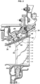
- FIG. 1 represents a cooling device for a crankcase according to the patent application FR3021700 , on behalf of the Applicant.
- This cooling device comprises collector housings 22, each collector housing 22 forming a channel extending axially.
- the device 21 further comprises tubes 23 extending circumferentially on either side of the collector housings 22.
- Said tubes 23, also called ramps, are formed by curved pipes of circular section, each tube 23 extending circumferentially around the casing for example at an angle of approximately 90 degrees.
- Each tube 23 has an air inlet opening into the channel of the corresponding collector housing 22 and a closed distal end.
- Each tube 23 further comprises a cylindrical wall provided with air ejection orifices facing the casing 18, so that cooling air can penetrate into the collector housings 22 then into the tubes 23, before emerging through the ejection orifices facing the casing 18, so as to cool it. This is particularly referred to as impact cooling since the air impacts the casing 18.
- the casing 18 comprises on its radially internal face, at least one annular hook which makes it possible to fix fixed blades or sealing ring sectors.
- the aforementioned technique of cooling by impact of air jets does not however make it possible to cool these hooks well. It would therefore be desirable to improve the cooling of the casing skin so as to improve the cooling of the hooks over their entire length and thus improve the thermal resistance at the end of the hook.
- the air used to cool the hooks is relatively hot due to convective exchanges with the radially external platform 38 of the distributor.
- the ducts which bring the cooling air from the inside of the blades to the hooks are relatively long, which means that the air undergoes additional heat exchanges in these ducts.
- An aim of the invention is to provide better cooling of the turbomachine casing hooks than the prior art solutions presented above.
- a turbomachine turbine casing said casing extending around an axis, comprising an annular wall and a cooling device, the wall being provided with at least one casing hook which projects radially from the inside of the wall, each hook being configured to allow the mounting, on the casing, of ring sectors arranged circumferentially end to end around the axis, and in which the cooling device comprises at least one collector duct intended for the conveyance of cooling air which extends circumferentially around the wall, each collector duct having a cooling air inlet and outlet.
- each collector duct and the wall have a common portion which delimits said collector duct and from which a corresponding hook extends and each collector duct is in fluid communication with a ventilation circuit which extends in the corresponding hook.
- the wall from which the hook extends constitutes a portion of the wall of the collector duct intended for the routing of cooling air.
- This configuration makes it possible to cool a larger portion of the exterior surface of said casing than can be cooled with prior art devices and thus to increase the service life of the casing.
- the proposed cooling device allows better cooling of the housing hook over its entire length, an increase in the life of the hook by limiting thermal gradients over the length of the hook, and by limiting tangential thermal gradients.
- airflow over circumferentially extending sectors provides better cooling of the hook tips and reduces angular thermal distortions.
- crankcase collector system helps to homogenize the crankcase cooling inlet temperature.
- the proposed cooling device allows less sampling flow to be taken to ensure the same thermal protection function of the casing.
- the proposed cooling device can be easily integrated into engine models consisting of a housing with hooks.
- the invention proposes a turbomachine comprising a turbine, and a turbine casing according to one of the preceding characteristics.
- FIG. 3 represents a turbomachine 1 with a double flow and a double body.
- the axis of the turbomachine is referenced X and corresponds to the axis of rotation of the rotating parts.
- the terms axial and radial are defined relative to the X axis.
- the turbomachine 1 comprises, from upstream to downstream in the direction of gas flow, a fan 2, a low-pressure compressor 3, a high-pressure compressor 4, a combustion chamber 5, a high-pressure turbine 6 and a low-pressure turbine 7.
- the air from the blower 2 is divided into a primary flow 8 flowing in a primary annular vein 9, and a secondary flow 10 flowing in a secondary annular vein 11 surrounding the primary annular vein 9.
- the low-pressure compressor 3, the high-pressure compressor 4, the combustion chamber 5, the high-pressure turbine 6 and the low-pressure turbine 7 are arranged in the primary vein 9.
- the rotor of the high-pressure turbine 6 and the rotor of the high-pressure compressor 4 are rotationally coupled via a first shaft 12 so as to form a high-pressure body.
- the rotor of the low-pressure turbine 7 and the rotor of the low-pressure compressor 3 are coupled in rotation via a second shaft 13, so as to form a low-pressure body, the blower 2 being able to be connected directly to the rotor of the low-pressure compressor 3 or via an epicyclic gear train for example.
- the low-pressure turbine 7 comprises in particular different successive stages comprising movable wheels 14 and fixed parts.
- the movable wheel comprises a disk 15, at the level of which blades 16 are mounted.
- the ends of the blades 16 are surrounded by a fixed ring 17 made of abradable material, said ring 17 being fixed to the casing 18 of the turbine.
- Distributors 19 are located upstream of the movable wheels 14.
- the distributors 19 and the rings 17 are mounted on the casing by means of flanges or hooks 20 extending from the radially internal surface of the casing 18.
- This casing 18 mainly supports the ring sectors which surround each movable wheel 14 and the distributor 19, thanks to the circumferential hooks 20 fixed to the casing.
- cooling device 100 of a turbine casing 130 such as a low-pressure turbine for a turbomachine 1, according to one embodiment of the invention.
- This cooling device 100 is integrated into the casing 130.
- the casing 130 comprises on a radial wall, an external surface 131, and an internal surface 132.
- the casing 130 further comprises a plurality of hooks 120 projecting radially inwards relative to its internal surface 132, the hooks 120 allowing, as previously described, the fixing of blades of a fixed blade (distributor) of the low-pressure turbine. and sealing ring sectors comprising an abradable element which is intended to be arranged radially opposite the moving blades of the rotor.
- the hooks 120 extend continuously over the circumference of the internal surface 132 so as to form an annular rail, and this in several axially offset positions of the casing 130.
- Reducing the clearance between the top of the moving blade and the casing 130 is a determining factor in the performance of the turbomachine because the smaller the radial clearances, the less flow bypassing the blade and the better the efficiency of the turbine.
- Controlling the clearances thus prevents the turbine from losing performance.
- it is indeed essential to control the clearances between the tips of the moving blades and a peripheral casing. Since the radial movement of this annular casing depends on the expansion of the casing 130, controlling the temperature of at least part of this casing 130 by fresh air is therefore essential.
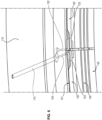
- the device 100 comprises a plurality of collector conduits 110 extending circumferentially around the casing 130 substantially over the entire periphery, i.e. substantially at 360°. In the exemplary embodiment shown in the figures 5 And 6 , there are two of these collector conduits 110.
- Each collector duct 110 surrounds the casing on respective circumferential portions of the casing 130.
- the hooks 120 are arranged on the circumference of the internal surface 132 of the casing 130, on several axially separated stages.
- each collector 110 is arranged so as to extend over a circumferential segment comprising a stage of hooks 120.
- the cooling device 100 comprises a plurality of collector conduits 110 arranged on as many stages of hooks 120 of the casing 130.
- Each collector duct 110 is connected to a supply duct 140.
- Said supply duct 140 is mainly radial and opens onto the external surface of the cooling device 100.
- the supply duct 140 is configured to take cold air from a sampling point; this is usually a point of the secondary gas flow vein of the machine, from which a portion of the flow is taken, in a manner known in the art.
- Each collector duct 110 is thus connected to a pressurized air supply source for conveying air into said duct 110.
- a collector duct 110 comprises an outer wall 111 (radially outer) and an inner wall 112 (radially inner), and two side walls 113 arranged on either side of the outer 111 and inner 112 walls.
- Two axially adjacent collector ducts 110 may be separated by a separation wall constituted by one of the side walls 113 common to the two adjacent collector ducts 110.
- the outer wall 111 has an orifice for connecting the collector conduit 110 to the supply conduit 140.
- the connection to the pressurized air supply source could be provided on any wall of the collector 110 except the inner wall 112.
- the external 111 and internal 112 walls are concentric, the collector duct 110 being able to have a trapezoidal cross section.
- the internal wall 112 is configured to match the shape of a circumferential segment of the casing 130, such that the internal wall 112 constitutes a part of the external surface (skin) of the casing 130.
- each collector duct 110 and the wall 112 provided with at least one hook 120 have a common portion 150, as can be seen in the figure 5 .
- This configuration makes it possible to cool a portion of the external surface of said casing 130 that is larger than that which can be cooled with the devices of the state of the art and thus to increase the service life of the casing 130.
- the collector duct 110 is a single piece and can be obtained by an additive manufacturing process, such as laser fusion.
- At least one hook 120 is not of solid section but comprises at least one ventilation circuit 121 comprising an inlet channel 122, an outlet channel 124, and an internal longitudinal channel 123 extending over the circumferential length of the hook 120 between the inlet channel 122 and the outlet channel 124.
- the inlet channel 122 makes it possible to connect the longitudinal channel 123 with the interior of the collector conduit 110.
- the inlet channel 122 is at the right of the hook 120.
- the outlet channel 124 makes it possible to connect the longitudinal channel 123 with the exterior of the casing 130 and the collector duct 110, by a passage 115 passing through the collector duct 110 and opening onto the surface of the external wall 111.
- the outlet channel 124 is at right angles to the hook 120.
- the outlet channel 124 makes it possible to connect the longitudinal channel 123 to a point of the turbomachine 1, where the pressure is lower than the pressure of the sampling point.
- the discharge point is in the central compartment (in English "core").
- the hooks 120 are configured for supporting ring sectors.
- the hooks 120 comprise an inlet channel 122 and an outlet channel 124 per ring sector.
- the inlet channel 122 and the outlet channel 124 are advantageously arranged at a first and a second circumferential position of the hook 120 corresponding to the circumferentially opposite ends of a sector.
- ring positioned in the hook 120.
- the circumferential length of the longitudinal channel 123 corresponds approximately to the circumferential length of a ring sector.
- the outlet channel 124 of a first ventilation circuit 121 is attached to the inlet channel 122 of a second ventilation circuit 121.
- the cooling device 100 makes it possible to use a pressurized air source and circulate it inside the hooks 120 of the casing 130 so as to increase the cooling capacity by pumping the cooling air.
- airflow over circumferentially extending sectors provides better cooling of the hook tips and reduces angular thermal distortions.
- the cooling device 100 therefore allows better cooling of the hook 120 of the casing 130 over its entire length, an increase in the service life of the hook by limiting the thermal gradients over the length of the hook 120, and by limiting the tangential thermal gradients.
- the collector duct system 110 of the casing 130 makes it possible to homogenize the cooling inlet temperature of the casing 130.
- the cooling device 100 allows less sampling flow to be taken to provide the same thermal protection function for the casing.
- cooling device 100 can be easily integrated into engine models comprising a housing with hooks.
- collector conduit could thus have other geometries.
Landscapes
- Engineering & Computer Science (AREA)
- Mechanical Engineering (AREA)
- General Engineering & Computer Science (AREA)
- Turbine Rotor Nozzle Sealing (AREA)
Claims (10)
- Turbinengehäuse (130) einer Turbomaschine (1), wobei sich das Gehäuse (130) um eine Achse (X) erstreckt, eine ringförmige Wand (112) und eine Kühlvorrichtung (100) umfasst, wobei die Wand (112) mit mindestens einem Gehäusehaken (120) versehen ist, der sich radial von der Innenseite der Wand (112) vorstehend erstreckt, wobei jeder Haken (120) so konfiguriert ist, dass er die Montage von Ringsektoren, die in Umfangsrichtung stirnseitig um die Achse (X) herum angeordnet sind, an dem Gehäuse (30) ermöglicht, und wobei die Kühlvorrichtung (100) mindestens einen Sammelkanal (110) für die Zufuhr von Kühlluft umfasst, der sich in Umfangsrichtung um die Wand (112) herum erstreckt, wobei jeder Sammelkanal (110) einen Kühllufteinlass und einen Kühlluftauslass aufweist, dadurch gekennzeichnet, dass jeder Sammelkanal (110) und die Wand (112) einen gemeinsamen Abschnitt (150) aufweisen, der den Sammelkanal (110) begrenzt und von dem aus sich ein entsprechender Haken (120) erstreckt und dass jeder Sammelkanal (110) in Fluidverbindung mit einem Belüftungskreislauf (121) steht, der sich in dem entsprechenden Haken (120) erstreckt.
- Turbinengehäuse (130) einer Turbomaschine (1) nach vorhergehendem Anspruch, wobei die Kühlvorrichtung (100) zwei axial benachbarte Sammelkanäle (110) umfasst, die durch eine Trennwand (113) voneinander getrennt sind.
- Turbinengehäuse (130) einer Turbomaschine (1) nach einem der vorhergehenden Ansprüche, wobei sich jeder Belüftungskreislauf (121) in dem größeren axialen Teil der axialen Erstreckung des entsprechenden Hakens (120) erstreckt.
- Turbinengehäuse (130) einer Turbomaschine (1) nach einem der vorhergehenden Ansprüche, wobei sich jeder Belüftungskreislauf (121) umfangsmäßig in dem entsprechenden Haken (120) erstreckt.
- Turbinengehäuse (130) einer Turbomaschine (1) nach vorhergehendem Anspruch, wobei der Einlass jedes Sammelkanals (110) mit einem Zuführrohr (140) verbunden ist, um Luft in den Sammelkanal (110) zu leiten.
- Turbinengehäuse (130) einer Turbomaschine (1) nach einem der vorhergehenden Ansprüche, wobei jeder Belüftungskreislauf (121) über einen Einlasskanal (122) hauptsächlich radial in den entsprechenden Sammelkanal (110) mündet.
- Turbinengehäuse (130) einer Turbomaschine (1) nach einem der vorhergehenden Ansprüche, wobei jeder Belüftungskreislauf (121) über einen Auslasskanal (124) an einer Außenfläche der Kühlvorrichtung (100) ausmündet.
- Turbinengehäuse (130) einer Turbomaschine (1) nach Anspruch 6 oder 7, wobei sich der Einlasskanal (122) und/oder der Auslasskanal (124) lotrecht über den entsprechenden Haken (120) erstreckt.
- Turbinengehäuse (130) einer Turbomaschine (1) nach den Ansprüchen 6 und 7, wobei sich der Einlasskanal (122) und der Auslasskanal (124) an einer ersten und einer zweiten Umfangsposition des entsprechenden Hakens (120) erstrecken, wobei die erste und die zweite Umfangsposition des entsprechenden Hakens (120) dazu bestimmt sind, mit den in Umfangsrichtung gegenüberliegenden Enden eines Ringsektors zusammenzufallen, der dazu bestimmt ist, an dem entsprechenden Haken (120) angebracht zu sein.
- Turbomaschine (1), die eine Turbine aufweist, dadurch gekennzeichnet, dass sie ein Turbinengehäuse (130) nach einem der vorhergehenden Ansprüche umfasst.
Applications Claiming Priority (2)
| Application Number | Priority Date | Filing Date | Title |
|---|---|---|---|
| FR2003894A FR3109406B1 (fr) | 2020-04-17 | 2020-04-17 | Dispositif de refroidissement d’un carter de turbine |
| PCT/FR2021/050650 WO2021209713A1 (fr) | 2020-04-17 | 2021-04-13 | Dispositif de refroidissement d'un carter de turbine |
Publications (2)
| Publication Number | Publication Date |
|---|---|
| EP4136327A1 EP4136327A1 (de) | 2023-02-22 |
| EP4136327B1 true EP4136327B1 (de) | 2024-08-21 |
Family
ID=72644292
Family Applications (1)
| Application Number | Title | Priority Date | Filing Date |
|---|---|---|---|
| EP21726693.1A Active EP4136327B1 (de) | 2020-04-17 | 2021-04-13 | Kühlvorrichtung für turbinengehäuse |
Country Status (5)
| Country | Link |
|---|---|
| US (1) | US11879347B2 (de) |
| EP (1) | EP4136327B1 (de) |
| CN (1) | CN115427664B (de) |
| FR (1) | FR3109406B1 (de) |
| WO (1) | WO2021209713A1 (de) |
Families Citing this family (1)
| Publication number | Priority date | Publication date | Assignee | Title |
|---|---|---|---|---|
| CN117869016B (zh) * | 2024-03-12 | 2024-05-17 | 中国航发四川燃气涡轮研究院 | 一种降低涡轮外环导热的冷却单元及其分析方法 |
Citations (1)
| Publication number | Priority date | Publication date | Assignee | Title |
|---|---|---|---|---|
| EP0892153B1 (de) * | 1997-07-18 | 2004-05-06 | Snecma Moteurs | Heiz- b.z.w. Kühleinrichtung für ein Gehäuse mit kreisförmigem Querschnitt |
Family Cites Families (9)
| Publication number | Priority date | Publication date | Assignee | Title |
|---|---|---|---|---|
| IT1137783B (it) * | 1981-08-03 | 1986-09-10 | Nuovo Pignone Spa | Scabiatore di calore integrato con la cassa statorica di una turbina a gas |
| US5205115A (en) * | 1991-11-04 | 1993-04-27 | General Electric Company | Gas turbine engine case counterflow thermal control |
| FR2803871B1 (fr) * | 2000-01-13 | 2002-06-07 | Snecma Moteurs | Agencement de reglage de diametre d'un stator de turbine a gaz |
| FR2816352B1 (fr) * | 2000-11-09 | 2003-01-31 | Snecma Moteurs | Ensemble de ventilation d'un anneau de stator |
| FR2819010B1 (fr) * | 2001-01-04 | 2004-05-28 | Snecma Moteurs | Secteur d'entretoise de support d'anneau de stator de la turbine haute pression d'une turbomachine avec rattrapage de jeux |
| FR2899281B1 (fr) | 2006-03-30 | 2012-08-10 | Snecma | Dispositif de refroidissement d'un carter de turbine d'une turbomachine |
| US9341074B2 (en) * | 2012-07-25 | 2016-05-17 | General Electric Company | Active clearance control manifold system |
| FR3021700B1 (fr) | 2014-05-27 | 2016-07-01 | Snecma | Dispositif de maintien d'un tube de refroidissement pour carter de turboreacteur |
| FR3067387B1 (fr) * | 2017-06-07 | 2019-06-28 | Safran Aircraft Engines | Ecope d'alimentation en air pour l'alimentation d'un systeme de refroidissement et de controle des jeux d'une turbine |
-
2020
- 2020-04-17 FR FR2003894A patent/FR3109406B1/fr active Active
-
2021
- 2021-04-13 US US17/919,184 patent/US11879347B2/en active Active
- 2021-04-13 EP EP21726693.1A patent/EP4136327B1/de active Active
- 2021-04-13 WO PCT/FR2021/050650 patent/WO2021209713A1/fr not_active Ceased
- 2021-04-13 CN CN202180028972.XA patent/CN115427664B/zh active Active
Patent Citations (1)
| Publication number | Priority date | Publication date | Assignee | Title |
|---|---|---|---|---|
| EP0892153B1 (de) * | 1997-07-18 | 2004-05-06 | Snecma Moteurs | Heiz- b.z.w. Kühleinrichtung für ein Gehäuse mit kreisförmigem Querschnitt |
Also Published As
| Publication number | Publication date |
|---|---|
| CN115427664B (zh) | 2025-07-04 |
| WO2021209713A1 (fr) | 2021-10-21 |
| CN115427664A (zh) | 2022-12-02 |
| FR3109406A1 (fr) | 2021-10-22 |
| US20230160319A1 (en) | 2023-05-25 |
| FR3109406B1 (fr) | 2022-10-07 |
| US11879347B2 (en) | 2024-01-23 |
| EP4136327A1 (de) | 2023-02-22 |
Similar Documents
| Publication | Publication Date | Title |
|---|---|---|
| FR2633666A1 (fr) | Stator d'un turboreacteur a double flux a rapport de dilution eleve | |
| WO2010142682A1 (fr) | Turbomachine comprenant des moyens ameliores de reglage du debit d'un flux d'air de refroidissement preleve en sortie de compresseur haute pression | |
| FR2872541A1 (fr) | Aube fixe de turbine a refroidissement ameliore | |
| EP4405569B1 (de) | Kühlluft-einspritzgehäuse für eine turbomaschinenturbine | |
| EP4010565B1 (de) | Deckband einer turbine einer turbomaschine oder eines turbotriebwerkes | |
| FR2919345A1 (fr) | Anneau pour une roue de turbine de turbomachine. | |
| EP1452695B1 (de) | Mit verringertem Kühlluftdurchstrom gekühlte Turbinenschaufel | |
| EP4409114A1 (de) | Hochdruckgasturbine für einen turbinenmotor sowie turbinenmotor | |
| WO2021209713A1 (fr) | Dispositif de refroidissement d'un carter de turbine | |
| EP3824221B1 (de) | Anordnung für eine turbomaschine | |
| FR3000985A1 (fr) | Dispositif de refroidissement pour un carter de turbine | |
| FR3111942A1 (fr) | Ensemble rotor d’une turbine basse pression d’une turbomachine | |
| EP3535479B1 (de) | Kühlvorrichtung für eine turbine einer turbomaschine | |
| CA3099889A1 (fr) | Dispositif de refroidissement d'un carter de turbomachine | |
| EP4298319A1 (de) | Turbinendichtring | |
| EP3983661B1 (de) | Vorrichtung zur kühlung des gehäuses einer turbomaschine | |
| FR3153847A1 (fr) | Dispositif de refroidissement d’un carter de turbomachine | |
| FR3068732A1 (fr) | Dispositif de refroidissement | |
| FR3061739A1 (fr) | Ensemble pour turbomachine | |
| FR3146932A1 (fr) | Architecture pour joint d’étanchéité de turbomachine | |
| FR3154755A1 (fr) | Dispositif de refroidissement par jets d’air d’un carter de turbine et turbomachine comportant un tel dispositif | |
| FR3121469A1 (fr) | Ensemble d’anneau de turbine pour une turbomachine | |
| FR3109961A1 (fr) | Distributeur en CMC amélioré pour turbine de turbomachine | |
| FR2970512A1 (fr) | Piece annulaire de guidage d'air autour d'une chambre de combustion dans une turbomachine |
Legal Events
| Date | Code | Title | Description |
|---|---|---|---|
| STAA | Information on the status of an ep patent application or granted ep patent |
Free format text: STATUS: UNKNOWN |
|
| STAA | Information on the status of an ep patent application or granted ep patent |
Free format text: STATUS: THE INTERNATIONAL PUBLICATION HAS BEEN MADE |
|
| PUAI | Public reference made under article 153(3) epc to a published international application that has entered the european phase |
Free format text: ORIGINAL CODE: 0009012 |
|
| STAA | Information on the status of an ep patent application or granted ep patent |
Free format text: STATUS: REQUEST FOR EXAMINATION WAS MADE |
|
| 17P | Request for examination filed |
Effective date: 20221115 |
|
| AK | Designated contracting states |
Kind code of ref document: A1 Designated state(s): AL AT BE BG CH CY CZ DE DK EE ES FI FR GB GR HR HU IE IS IT LI LT LU LV MC MK MT NL NO PL PT RO RS SE SI SK SM TR |
|
| DAV | Request for validation of the european patent (deleted) | ||
| DAX | Request for extension of the european patent (deleted) | ||
| GRAP | Despatch of communication of intention to grant a patent |
Free format text: ORIGINAL CODE: EPIDOSNIGR1 |
|
| STAA | Information on the status of an ep patent application or granted ep patent |
Free format text: STATUS: GRANT OF PATENT IS INTENDED |
|
| INTG | Intention to grant announced |
Effective date: 20240507 |
|
| GRAS | Grant fee paid |
Free format text: ORIGINAL CODE: EPIDOSNIGR3 |
|
| GRAA | (expected) grant |
Free format text: ORIGINAL CODE: 0009210 |
|
| STAA | Information on the status of an ep patent application or granted ep patent |
Free format text: STATUS: THE PATENT HAS BEEN GRANTED |
|
| AK | Designated contracting states |
Kind code of ref document: B1 Designated state(s): AL AT BE BG CH CY CZ DE DK EE ES FI FR GB GR HR HU IE IS IT LI LT LU LV MC MK MT NL NO PL PT RO RS SE SI SK SM TR |
|
| REG | Reference to a national code |
Ref country code: GB Ref legal event code: FG4D Free format text: NOT ENGLISH |
|
| REG | Reference to a national code |
Ref country code: CH Ref legal event code: EP |
|
| REG | Reference to a national code |
Ref country code: DE Ref legal event code: R096 Ref document number: 602021017541 Country of ref document: DE |
|
| REG | Reference to a national code |
Ref country code: IE Ref legal event code: FG4D Free format text: LANGUAGE OF EP DOCUMENT: FRENCH |
|
| REG | Reference to a national code |
Ref country code: LT Ref legal event code: MG9D |
|
| REG | Reference to a national code |
Ref country code: NL Ref legal event code: MP Effective date: 20240821 |
|
| PG25 | Lapsed in a contracting state [announced via postgrant information from national office to epo] |
Ref country code: NO Free format text: LAPSE BECAUSE OF FAILURE TO SUBMIT A TRANSLATION OF THE DESCRIPTION OR TO PAY THE FEE WITHIN THE PRESCRIBED TIME-LIMIT Effective date: 20241121 |
|
| REG | Reference to a national code |
Ref country code: AT Ref legal event code: MK05 Ref document number: 1715660 Country of ref document: AT Kind code of ref document: T Effective date: 20240821 |
|
| PG25 | Lapsed in a contracting state [announced via postgrant information from national office to epo] |
Ref country code: NL Free format text: LAPSE BECAUSE OF FAILURE TO SUBMIT A TRANSLATION OF THE DESCRIPTION OR TO PAY THE FEE WITHIN THE PRESCRIBED TIME-LIMIT Effective date: 20240821 Ref country code: FI Free format text: LAPSE BECAUSE OF FAILURE TO SUBMIT A TRANSLATION OF THE DESCRIPTION OR TO PAY THE FEE WITHIN THE PRESCRIBED TIME-LIMIT Effective date: 20240821 Ref country code: GR Free format text: LAPSE BECAUSE OF FAILURE TO SUBMIT A TRANSLATION OF THE DESCRIPTION OR TO PAY THE FEE WITHIN THE PRESCRIBED TIME-LIMIT Effective date: 20241122 Ref country code: PL Free format text: LAPSE BECAUSE OF FAILURE TO SUBMIT A TRANSLATION OF THE DESCRIPTION OR TO PAY THE FEE WITHIN THE PRESCRIBED TIME-LIMIT Effective date: 20240821 Ref country code: PT Free format text: LAPSE BECAUSE OF FAILURE TO SUBMIT A TRANSLATION OF THE DESCRIPTION OR TO PAY THE FEE WITHIN THE PRESCRIBED TIME-LIMIT Effective date: 20241223 |
|
| PG25 | Lapsed in a contracting state [announced via postgrant information from national office to epo] |
Ref country code: BG Free format text: LAPSE BECAUSE OF FAILURE TO SUBMIT A TRANSLATION OF THE DESCRIPTION OR TO PAY THE FEE WITHIN THE PRESCRIBED TIME-LIMIT Effective date: 20240821 |
|
| PG25 | Lapsed in a contracting state [announced via postgrant information from national office to epo] |
Ref country code: LV Free format text: LAPSE BECAUSE OF FAILURE TO SUBMIT A TRANSLATION OF THE DESCRIPTION OR TO PAY THE FEE WITHIN THE PRESCRIBED TIME-LIMIT Effective date: 20240821 |
|
| PG25 | Lapsed in a contracting state [announced via postgrant information from national office to epo] |
Ref country code: AT Free format text: LAPSE BECAUSE OF FAILURE TO SUBMIT A TRANSLATION OF THE DESCRIPTION OR TO PAY THE FEE WITHIN THE PRESCRIBED TIME-LIMIT Effective date: 20240821 Ref country code: IS Free format text: LAPSE BECAUSE OF FAILURE TO SUBMIT A TRANSLATION OF THE DESCRIPTION OR TO PAY THE FEE WITHIN THE PRESCRIBED TIME-LIMIT Effective date: 20241221 |
|
| PG25 | Lapsed in a contracting state [announced via postgrant information from national office to epo] |
Ref country code: HR Free format text: LAPSE BECAUSE OF FAILURE TO SUBMIT A TRANSLATION OF THE DESCRIPTION OR TO PAY THE FEE WITHIN THE PRESCRIBED TIME-LIMIT Effective date: 20240821 |
|
| PG25 | Lapsed in a contracting state [announced via postgrant information from national office to epo] |
Ref country code: RS Free format text: LAPSE BECAUSE OF FAILURE TO SUBMIT A TRANSLATION OF THE DESCRIPTION OR TO PAY THE FEE WITHIN THE PRESCRIBED TIME-LIMIT Effective date: 20241121 Ref country code: ES Free format text: LAPSE BECAUSE OF FAILURE TO SUBMIT A TRANSLATION OF THE DESCRIPTION OR TO PAY THE FEE WITHIN THE PRESCRIBED TIME-LIMIT Effective date: 20240821 |
|
| PG25 | Lapsed in a contracting state [announced via postgrant information from national office to epo] |
Ref country code: RS Free format text: LAPSE BECAUSE OF FAILURE TO SUBMIT A TRANSLATION OF THE DESCRIPTION OR TO PAY THE FEE WITHIN THE PRESCRIBED TIME-LIMIT Effective date: 20241121 Ref country code: PT Free format text: LAPSE BECAUSE OF FAILURE TO SUBMIT A TRANSLATION OF THE DESCRIPTION OR TO PAY THE FEE WITHIN THE PRESCRIBED TIME-LIMIT Effective date: 20241223 Ref country code: PL Free format text: LAPSE BECAUSE OF FAILURE TO SUBMIT A TRANSLATION OF THE DESCRIPTION OR TO PAY THE FEE WITHIN THE PRESCRIBED TIME-LIMIT Effective date: 20240821 Ref country code: NO Free format text: LAPSE BECAUSE OF FAILURE TO SUBMIT A TRANSLATION OF THE DESCRIPTION OR TO PAY THE FEE WITHIN THE PRESCRIBED TIME-LIMIT Effective date: 20241121 Ref country code: NL Free format text: LAPSE BECAUSE OF FAILURE TO SUBMIT A TRANSLATION OF THE DESCRIPTION OR TO PAY THE FEE WITHIN THE PRESCRIBED TIME-LIMIT Effective date: 20240821 Ref country code: LV Free format text: LAPSE BECAUSE OF FAILURE TO SUBMIT A TRANSLATION OF THE DESCRIPTION OR TO PAY THE FEE WITHIN THE PRESCRIBED TIME-LIMIT Effective date: 20240821 Ref country code: IS Free format text: LAPSE BECAUSE OF FAILURE TO SUBMIT A TRANSLATION OF THE DESCRIPTION OR TO PAY THE FEE WITHIN THE PRESCRIBED TIME-LIMIT Effective date: 20241221 Ref country code: HR Free format text: LAPSE BECAUSE OF FAILURE TO SUBMIT A TRANSLATION OF THE DESCRIPTION OR TO PAY THE FEE WITHIN THE PRESCRIBED TIME-LIMIT Effective date: 20240821 Ref country code: GR Free format text: LAPSE BECAUSE OF FAILURE TO SUBMIT A TRANSLATION OF THE DESCRIPTION OR TO PAY THE FEE WITHIN THE PRESCRIBED TIME-LIMIT Effective date: 20241122 Ref country code: FI Free format text: LAPSE BECAUSE OF FAILURE TO SUBMIT A TRANSLATION OF THE DESCRIPTION OR TO PAY THE FEE WITHIN THE PRESCRIBED TIME-LIMIT Effective date: 20240821 Ref country code: ES Free format text: LAPSE BECAUSE OF FAILURE TO SUBMIT A TRANSLATION OF THE DESCRIPTION OR TO PAY THE FEE WITHIN THE PRESCRIBED TIME-LIMIT Effective date: 20240821 Ref country code: BG Free format text: LAPSE BECAUSE OF FAILURE TO SUBMIT A TRANSLATION OF THE DESCRIPTION OR TO PAY THE FEE WITHIN THE PRESCRIBED TIME-LIMIT Effective date: 20240821 Ref country code: AT Free format text: LAPSE BECAUSE OF FAILURE TO SUBMIT A TRANSLATION OF THE DESCRIPTION OR TO PAY THE FEE WITHIN THE PRESCRIBED TIME-LIMIT Effective date: 20240821 |
|
| PG25 | Lapsed in a contracting state [announced via postgrant information from national office to epo] |
Ref country code: DK Free format text: LAPSE BECAUSE OF FAILURE TO SUBMIT A TRANSLATION OF THE DESCRIPTION OR TO PAY THE FEE WITHIN THE PRESCRIBED TIME-LIMIT Effective date: 20240821 Ref country code: SM Free format text: LAPSE BECAUSE OF FAILURE TO SUBMIT A TRANSLATION OF THE DESCRIPTION OR TO PAY THE FEE WITHIN THE PRESCRIBED TIME-LIMIT Effective date: 20240821 Ref country code: RO Free format text: LAPSE BECAUSE OF FAILURE TO SUBMIT A TRANSLATION OF THE DESCRIPTION OR TO PAY THE FEE WITHIN THE PRESCRIBED TIME-LIMIT Effective date: 20240821 |
|
| PG25 | Lapsed in a contracting state [announced via postgrant information from national office to epo] |
Ref country code: EE Free format text: LAPSE BECAUSE OF FAILURE TO SUBMIT A TRANSLATION OF THE DESCRIPTION OR TO PAY THE FEE WITHIN THE PRESCRIBED TIME-LIMIT Effective date: 20240821 |
|
| PG25 | Lapsed in a contracting state [announced via postgrant information from national office to epo] |
Ref country code: CZ Free format text: LAPSE BECAUSE OF FAILURE TO SUBMIT A TRANSLATION OF THE DESCRIPTION OR TO PAY THE FEE WITHIN THE PRESCRIBED TIME-LIMIT Effective date: 20240821 |
|
| PG25 | Lapsed in a contracting state [announced via postgrant information from national office to epo] |
Ref country code: SK Free format text: LAPSE BECAUSE OF FAILURE TO SUBMIT A TRANSLATION OF THE DESCRIPTION OR TO PAY THE FEE WITHIN THE PRESCRIBED TIME-LIMIT Effective date: 20240821 Ref country code: IT Free format text: LAPSE BECAUSE OF FAILURE TO SUBMIT A TRANSLATION OF THE DESCRIPTION OR TO PAY THE FEE WITHIN THE PRESCRIBED TIME-LIMIT Effective date: 20240821 |
|
| REG | Reference to a national code |
Ref country code: DE Ref legal event code: R097 Ref document number: 602021017541 Country of ref document: DE |
|
| PLBE | No opposition filed within time limit |
Free format text: ORIGINAL CODE: 0009261 |
|
| STAA | Information on the status of an ep patent application or granted ep patent |
Free format text: STATUS: NO OPPOSITION FILED WITHIN TIME LIMIT |
|
| PGFP | Annual fee paid to national office [announced via postgrant information from national office to epo] |
Ref country code: DE Payment date: 20250417 Year of fee payment: 5 |
|
| PGFP | Annual fee paid to national office [announced via postgrant information from national office to epo] |
Ref country code: FR Payment date: 20250428 Year of fee payment: 5 |
|
| 26N | No opposition filed |
Effective date: 20250522 |
|
| PG25 | Lapsed in a contracting state [announced via postgrant information from national office to epo] |
Ref country code: SE Free format text: LAPSE BECAUSE OF FAILURE TO SUBMIT A TRANSLATION OF THE DESCRIPTION OR TO PAY THE FEE WITHIN THE PRESCRIBED TIME-LIMIT Effective date: 20240821 |
|
| REG | Reference to a national code |
Ref country code: CH Ref legal event code: H13 Free format text: ST27 STATUS EVENT CODE: U-0-0-H10-H13 (AS PROVIDED BY THE NATIONAL OFFICE) Effective date: 20251125 |
|
| PG25 | Lapsed in a contracting state [announced via postgrant information from national office to epo] |
Ref country code: LU Free format text: LAPSE BECAUSE OF NON-PAYMENT OF DUE FEES Effective date: 20250413 |
|
| PG25 | Lapsed in a contracting state [announced via postgrant information from national office to epo] |
Ref country code: MC Free format text: LAPSE BECAUSE OF FAILURE TO SUBMIT A TRANSLATION OF THE DESCRIPTION OR TO PAY THE FEE WITHIN THE PRESCRIBED TIME-LIMIT Effective date: 20240821 |
|
| REG | Reference to a national code |
Ref country code: BE Ref legal event code: MM Effective date: 20250430 |
|
| PG25 | Lapsed in a contracting state [announced via postgrant information from national office to epo] |
Ref country code: BE Free format text: LAPSE BECAUSE OF NON-PAYMENT OF DUE FEES Effective date: 20250430 |
|
| PG25 | Lapsed in a contracting state [announced via postgrant information from national office to epo] |
Ref country code: CH Free format text: LAPSE BECAUSE OF NON-PAYMENT OF DUE FEES Effective date: 20250430 |
|
| PGFP | Annual fee paid to national office [announced via postgrant information from national office to epo] |
Ref country code: GB Payment date: 20260327 Year of fee payment: 6 |
|
| PG25 | Lapsed in a contracting state [announced via postgrant information from national office to epo] |
Ref country code: IE Free format text: LAPSE BECAUSE OF NON-PAYMENT OF DUE FEES Effective date: 20250413 |