EP4136958B1 - Appareil et procédé de réglage de plaque frontale d'un dispositif d'alimentation pour véhicule agricole - Google Patents
Appareil et procédé de réglage de plaque frontale d'un dispositif d'alimentation pour véhicule agricole Download PDFInfo
- Publication number
- EP4136958B1 EP4136958B1 EP22190689.4A EP22190689A EP4136958B1 EP 4136958 B1 EP4136958 B1 EP 4136958B1 EP 22190689 A EP22190689 A EP 22190689A EP 4136958 B1 EP4136958 B1 EP 4136958B1
- Authority
- EP
- European Patent Office
- Prior art keywords
- feeder
- faceplate
- threaded shaft
- agricultural vehicle
- header
- Prior art date
- Legal status (The legal status is an assumption and is not a legal conclusion. Google has not performed a legal analysis and makes no representation as to the accuracy of the status listed.)
- Active
Links
Images


Classifications
-
- A—HUMAN NECESSITIES
- A01—AGRICULTURE; FORESTRY; ANIMAL HUSBANDRY; HUNTING; TRAPPING; FISHING
- A01D—HARVESTING; MOWING
- A01D41/00—Combines, i.e. harvesters or mowers combined with threshing devices
- A01D41/12—Details of combines
- A01D41/14—Mowing tables
- A01D41/16—Devices for coupling mowing tables to conveyors
-
- A—HUMAN NECESSITIES
- A01—AGRICULTURE; FORESTRY; ANIMAL HUSBANDRY; HUNTING; TRAPPING; FISHING
- A01D—HARVESTING; MOWING
- A01D41/00—Combines, i.e. harvesters or mowers combined with threshing devices
- A01D41/06—Combines with headers
-
- A—HUMAN NECESSITIES
- A01—AGRICULTURE; FORESTRY; ANIMAL HUSBANDRY; HUNTING; TRAPPING; FISHING
- A01D—HARVESTING; MOWING
- A01D61/00—Elevators or conveyors for binders or combines
- A01D61/008—Elevators or conveyors for binders or combines for longitudinal conveying, especially for combines
Definitions
- the present invention relates to agricultural harvesters. More specifically, the present invention relates to an apparatus and method for adjusting a position of a faceplate of a feeder for an agricultural vehicle, such as a combine harvester.
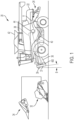
- FIG. 1 depicts a self-propelled agricultural combine 20.
- Combine 20 has a front end to which a header 32 can be connected.
- Header 32 is commonly referred to as a grain header and is typically utilized for harvesting smaller grains, such as, but not limited to, wheat and soybeans.
- Another well-known header 34 is shown, which is a corn header. Corn header 34 can also be connected to combine 20. Headers 32 and 34, as well as other headers (not shown), are configured to be interchangeably mounted on the front end of a feeder 36 of combine 20 for configuring combine 20 to harvest a particular crop.
- the crops harvested by a header will be gathered up by the header 32/34 and conveyed by feeder 36 (also referred to in the art as a feederhouse) rearwardly and upwardly into the body of the combine 20, for processing by a threshing system 38.
- System 38 is operable for threshing and separating grain from larger elements of crop material, such as stems, leaves, cobs and larger fragments of pods, such that the grain will fall into a cleaning system 40, which will further process or clean smaller elements of crop residue from the grain, and the grain will be conveyed to a grain tank 42 or other collector.
- Headers 32 and 34 are interchangeably attached to a faceplate 37 on the free end of feeder 36.
- headers 32/34 include couplers for releasably mounting to a coupling 39 on faceplate 37.
- a feeder faceplate angle B can be adjusted to accommodate the particular header 32/34. Angle B may also be adjusted due to crop conditions, ground conditions, and more. Angle B may be defined as the fore/aft pitch angle of the feeder.
- feeder faceplate 37 rotates along a transverse axis passing through feeder 36 (e.g., an axis passing through the page of FIG. 1 ), and feeder faceplate angle B represents rotation about that axis.
- US6330782B1 describes a mechanism for manually and automatically adjusting the front support drum of an endless conveyor within the feederhouse of an agricultural combine.
- the front drum is rotatably affixed to the remote end of a pivot arm that is pivotably affixed to the side sheet of the feederhouse.
- the relative position of the drum to the floor of the feederhouse is manually adjustable by manipulation of a cam that moves the pivot arm toward and away from the floor to preset positions.
- a pivot mounting for the pivot arm that allows the drum to move upwardly and rearwardly when a bulk or lump of crop material enters the opening between the drum and the floor, thereby preventing damage to the components of the feederhouse.
- a feeder for an agricultural vehicle includes a feeder body defining a hollow interior space for receiving crop material from a header of the agricultural vehicle, a faceplate that is movably mounted to the feeder body, and a scissor jack assembly that is configured for rotating the faceplate with respect to the feeder body to adjust a fore-aft angle of the faceplate relative to the feeder body.
- the faceplate is configured to be removably coupled to the header of the agricultural vehicle.
- forward when used in connection with the agricultural harvester and/or components thereof are usually determined with reference to the direction of forward operative travel of the harvester, but again, they should not be construed as limiting.
- longitudinal and “transverse” are determined with reference to the fore-and-aft direction of the agricultural harvester and are equally not to be construed as limiting.
- upstream and “downstream” are determined with reference to the crop flow stream arrows shown in FIG. 1 .
- feeder 36 includes a body 35 having a hollow interior for receiving crop material from the header 32/34.
- Faceplate 37 is mounted to the forward end of feeder body 35. Faceplate 37 may not be permanently mounted to feeder body 35, however, it is not readily and easily removable from feeder body 35.
- Faceplate 37 includes one or more couplings 39 that are configured to be releasably connected to mating couplings on header 32/34, as was described above. Couplings 39 may be located anywhere on faceplate 37, and are not limited to that which is shown. Couplings 39 may be hinges, bolts, hooks, fasteners, or any other couplings known in the agricultural vehicle arts.
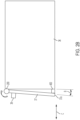
- Faceplate 37 is mounted to the top side of faceplate 37 by a hinge 200, such that faceplate 37 is capable of being rotated about hinge 200 (see curved arrow) with respect to feeder body 35. As was noted above, it may be necessary to rotate faceplate 37 about hinge 200 to accommodate various header styles or to adjust the position of a header relative to the ground. Rotating the faceplate 37 changes the feeder faceplate angle ⁇ B' as well as the distance between bottom side 37a of feeder 37 (as measured along fore-aft axis 'C').
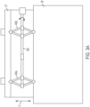
- a scissor jack assembly 400 (referred to hereinafter as assembly 400) is configured to rotate faceplate 37 with respect to feeder body 35.
- Assembly 400 is mounted at the bottom side 37a of faceplate 37 at a location (i) between the forward side of feeder body 35 and the rear side of faceplate 37, and (ii) beneath hinge 200.
- Assembly 400 extends transversely along axis D ( FIG. 2A ). It should be understood that location of assembly 400 is not limited to that which is shown. For example, assembly 400 may be positioned closer to the top end of faceplate 37 and hinge 200 may be positioned at the bottom end of faceplate 37, or, assembly 400 could extend vertically (as opposed to transversely).
- assembly 400 comprises a threaded shaft 402 including threaded segments (i.e., mechanical threads) extending along its length as well as non-threaded segments.
- the segments of threaded shaft 402 may be interconnected by couplings 422, sleeves, bolts, etc.
- a first scissor jack 404a is mounted to one side of threaded shaft 402, and a second scissor jack 404b is mounted to an opposing side of threaded shaft 402.
- Scissor jacks 404a and 404b are substantially identical, and may be referred to herein either individually or collectively as jack(s) 404. Although only one jack 404 will be described hereinafter, it should be understood that foregoing description also applies to the other jack 404.
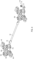
- Jack 404 includes two connected arms 405a and 405b each having one end that is pivotably connected to a hinge 208. Hinge 208 pivotably interconnects jack 404 with faceplate 37. As best shown in FIG. 4 , hinge 208 optionally includes two knuckles defining an open passageway through which a rod (not shown) passes. The rod is connected to faceplate 37. Hinge 208 can pivot about the rod. The other end of arms 405a and 405b are pivotably mounted to pins 407a and 407b, respectively. Each pin 407 includes a threaded opening that is threadedly connected to threads of threaded shaft 402, such that rotation of threaded shaft 402 causes translation of pins 407.
- Jack 404 also includes two connected arms 406a and 406b each having one end that is pivotably connected to a hinge 409. Hinge 409 pivotably interconnects jack 404 with feeder body 35. As best shown in FIG. 4 , hinge 409 optionally includes one knuckle defining an open passageway through which a rod (not shown) passes. The rod is connected to feeder body 35. Hinge 209 can pivot about the rod. The other end of arms 406a and 406b are pivotably mounted to pins 407a and 407b, respectively. Pins 407a and 407b may be referred to collectively as pins 407.
- Pin 407a is connected to a righthand thread on threaded shaft 402, and pin 407b is connected to a left-hand thread on threaded shaft 402, or vice versa, such that pins 407a and 407b translate along axis D in opposite directions upon rotating threaded shaft 402.
- pins 407 of jack 404a translate toward each other, and, pins 407 of jack 404b also translate toward each other.
- Jacks 404a and 404b move in concert (simultaneously) with each other because they are connected to a common threaded shaft 402.
- arms 405a/b and 406a/b rotate inwardly along a transverse axis D and extend outwardly along the fore-aft axis C. Consequently, starting from the partially extended (i.e., rotated) position or state of assembly 400 shown in FIGs.
- pins 407 of jack 404a translate away from each other, and, pins 407 of jack 404b also translate away from each other.
- arms 405a/b and 406a/b rotate outwardly along a transverse axis D and extend inwardly along the fore-aft axis C. Consequently, starting from the fully extended (i.e., rotated) state of assembly 400' shown in FIGs.
- the end 37a of faceplate 37 rotates toward feeder body 35 and the feeder faceplate angle ⁇ B' decreases until the end 37a of faceplate 37 reaches the partially extended (i.e., rotated) position 400 shown in FIGs. 2A / 2B .
- further rotation is possible until the feeder faceplate angle ⁇ B' reaches a value of zero.
- the free end of threaded shaft 402 may be hexagonal, square, or, more generally, non-circular, as viewed in cross-section.
- the free end of threaded shaft 402 may be rotated manually by a wrench or driver, for example.
- threaded shaft 402 may be rotated in an automated fashion by a motor 410 that is controlled by an operator in the cab of combine 20, for example.
- Motor 410, or a transmission connected thereto, may be self-locking to prevent inadvertent rotation of faceplate 37.
- Motor 410 may be powered electrically or hydraulically, for example.
- lock 415 in the form of a plate may be connected to threaded shaft 402 to prevent inadvertent rotation of threaded shaft 402. More particularly, lock 415 includes a first opening 417 having a shape that is complementary to the non-circular cross-sectional shape of the free end of threaded shaft 402 such that threaded shaft 402 and first opening 417 are connected in a non-rotatable manner. Lock 415 includes a second opening for receiving a threaded fastener 420. Fastener 420 can be connected to faceplate 37, feeder 36, or another fixed point on combine 20. It should be understood that rotation of threaded shaft 402, and consequent movement of jacks 404, is prevented when lock 415 is mounted to threaded shaft 402 and fastener 420 is connected to a fixed point.
- lock 415 may vary from that which is shown.
- Lock 415 can be any device that is configured to resist rotation of threaded shaft 402.
- Lock 415 may be a collar, collet, fastener, clip, pin, clamp, and so forth. For that reason, lock 415 may also be referred to herein as a locking device or "means for locking" the threaded shaft 402.
- Assembly 400 may vary from that which is shown and described. It should also be understood that the details of jack 404 can vary, and different styles of jacks are known to those skilled in the art (e.g., scissor, jackscrew, house, floor, bottle, inflatable, air hydraulic, strand, farm, etc.).
- assembly 400 shown in FIGs. 2B and 3B may simply represent a motor having a protruding piston, wherein the motor is mounted to the feeder body 35 and the piston is mounted to faceplate 37. The motor may be powered electrically or hydraulically, for example.
- assembly 400 may be generally referred to herein as a "means for moving" faceplate with respect to feeder body 35.
- the scissor jack assembly 400 can include one jack 404 or two (or more) interconnected jacks 404, as shown.
- the scissor jack assembly 404 may be positioned on either the top or the bottom of the feeder.
- the shaft 402 may be on the top, middle or bottom side of the feeder or at any position in between.
- Other alternatives and modifications are described above.
Landscapes
- Life Sciences & Earth Sciences (AREA)
- Environmental Sciences (AREA)
- Harvester Elements (AREA)
- Automatic Assembly (AREA)
- Automobile Manufacture Line, Endless Track Vehicle, Trailer (AREA)
Claims (14)
- Un engreneur (36) destiné à être couplé à un organe de coupe (32/34) d'un véhicule agricole (20), ledit engreneur comprenant :un corps d'engreneur (35) définissant un espace intérieur creux pour la réception du matériau récolté en provenance de l'organe de coupe (32/34),une plaque avant (37) qui est montée de manière mobile sur le corps d'engreneur (35), dans lequel la plaque avant (37) est configurée pour être couplée de manière amovible à l'organe de coupe (32/34) du véhicule agricole,caractérisé en ce que l'engreneur (36) comprend en outre un ensemble vérin à ciseaux (400) qui est configuré pour faire pivoter la plaque avant (37) par rapport au corps d'engreneur (35) afin d'ajuster un angle longitudinal (B) de la plaque avant (37) par rapport au corps d'engreneur (35).
- L'engreneur selon la revendication 1, dans lequel l'engreneur (36) comprend en outre un coupleur (39) monté sur la plaque avant (37) qui est configuré pour être monté sur l'organe de coupe (32/34) du véhicule agricole.
- L'engreneur selon la revendication 1 ou la revendication 2, dans lequel l'engreneur (36) comprend en outre une charnière (200) pour raccorder de manière pivotante la plaque avant (37) au corps d'engreneur (35).
- L'engreneur selon la revendication 3, dans lequel la charnière (200) est positionnée à une hauteur supérieure à l'ensemble vérin à ciseaux (400).
- L'engreneur selon l'une quelconque des revendications précédentes, dans lequel l'ensemble vérin à ciseaux (400) est configuré pour faire pivoter la plaque avant (37) autour d'un axe transversal de l'engreneur ou du véhicule agricole (20) afin d'ajuster l'angle longitudinal (B) de la plaque avant (37).
- L'engreneur selon l'une quelconque des revendications précédentes, dans lequel l'ensemble vérin à ciseaux (400) comprend un arbre fileté (402) et au moins un vérin à ciseaux (404) qui est raccordé à l'arbre fileté (402), dans lequel la rotation de l'arbre fileté (402) entraîne le mouvement du vérin à ciseaux (404) qui provoque la rotation de la plaque avant (37) par rapport au corps d'engreneur (35).
- L'engreneur selon la revendication 6, dans lequel l'engreneur (36) comprend en outre deux vérins à ciseaux (404) montés sur l'arbre fileté (402), dans lequel la rotation de l'arbre fileté (402) entraîne le mouvement desdits deux vérins à ciseaux (404).
- L'engreneur selon la revendication 6 ou la revendication 7, dans lequel l'engreneur (36) comprend en outre un moteur (410) pour faire pivoter ledit arbre fileté (402).
- L'engreneur selon l'une quelconque des revendications 6 à 8, dans lequel l'engreneur (36) comprend en outre un verrou (415) qui est raccordé de manière amovible à l'arbre fileté (402) pour empêcher la rotation de l'arbre fileté (402).
- L'engreneur selon la revendication 9, dans lequel le verrou (415) comprend une ouverture (417) destinée à recevoir l'arbre fileté (402) de manière non rotative, et une attache (420) destinée à être montée sur l'un parmi le corps d'engreneur (35), la plaque avant (37) et un point fixe sur le véhicule agricole pour empêcher la rotation de l'arbre fileté (402).
- L'engreneur selon la revendication 10, dans lequel l'ouverture (417) a une forme qui est complémentaire d'une forme en coupe transversale de l'arbre fileté (402).
- Un sous-ensemble comprenant l'organe de coupe (32/34) monté sur l'engreneur (36) selon l'une quelconque des revendications précédentes.
- Un véhicule agricole comprenant l'engreneur selon l'une quelconque des revendications 1 à 11.
- Le véhicule agricole selon la revendication 13, dans lequel le véhicule agricole est une moissonneuse-batteuse.
Applications Claiming Priority (1)
| Application Number | Priority Date | Filing Date | Title |
|---|---|---|---|
| US17/406,514 US12102038B2 (en) | 2021-08-19 | 2021-08-19 | Apparatus and method for adjusting faceplate of feeder for agricultural vehicle |
Publications (2)
| Publication Number | Publication Date |
|---|---|
| EP4136958A1 EP4136958A1 (fr) | 2023-02-22 |
| EP4136958B1 true EP4136958B1 (fr) | 2024-11-20 |
Family
ID=82943283
Family Applications (1)
| Application Number | Title | Priority Date | Filing Date |
|---|---|---|---|
| EP22190689.4A Active EP4136958B1 (fr) | 2021-08-19 | 2022-08-17 | Appareil et procédé de réglage de plaque frontale d'un dispositif d'alimentation pour véhicule agricole |
Country Status (3)
| Country | Link |
|---|---|
| US (1) | US12102038B2 (fr) |
| EP (1) | EP4136958B1 (fr) |
| BR (1) | BR102022015514A2 (fr) |
Family Cites Families (17)
| Publication number | Priority date | Publication date | Assignee | Title |
|---|---|---|---|---|
| EP0448844B1 (fr) | 1990-03-27 | 1993-12-15 | New Holland Belgium N.V. | Dispositif convoyeur de moissonneuse-batteuse pour accoupler le tablier de coupe à l'unité de base |
| US5460460A (en) * | 1994-03-01 | 1995-10-24 | The Serco Corporation | Scissors lift dock leveler |
| US5918448A (en) | 1997-02-06 | 1999-07-06 | Agco Corporation | Combine header lateral tilt assembly |
| RU2157613C1 (ru) | 1999-03-12 | 2000-10-20 | Открытое акционерное общество "Тульский комбайновый завод" | Кормоуборочный комбайн |
| US6116008A (en) | 1999-04-01 | 2000-09-12 | New Holland North America, Inc. | Pivoting faceplate for a feederhouse on an agricultural combine |
| DE19916645B4 (de) | 1999-04-14 | 2005-12-29 | Deere & Company, Moline | Fördererzusammenbau |
| AUPQ990000A0 (en) | 2000-09-01 | 2000-09-28 | Schutt, Craig James | Combine harvesters |
| US20080256914A1 (en) * | 2007-04-23 | 2008-10-23 | Ricketts Jonathan E | Method and device for automatically coupling a combine feeder interface and a combine header via a stationary gearbox |
| US8010262B2 (en) | 2009-10-21 | 2011-08-30 | Cnh America Llc | Apparatus and method for automatically controlling the settings of an adjustable crop residue spreader of an agricultural combine |
| BE1022551B1 (nl) * | 2014-11-27 | 2016-05-31 | Cnh Industrial Belgium Nv | Oogstmachine voor gebruik in de landbouw |
| US9844184B2 (en) | 2015-03-17 | 2017-12-19 | Agco Corporation | Header position sensing system for an agricultural harvester |
| BE1022622B1 (nl) * | 2015-03-27 | 2016-06-17 | Cnh Industrial Belgium Nv | Maaiermontageframe |
| DE102015107090A1 (de) | 2015-05-06 | 2016-11-10 | Claas Selbstfahrende Erntemaschinen Gmbh | Schnittwinkelverstellung eines Schneidwerks |
| GB201607568D0 (en) * | 2016-04-29 | 2016-06-15 | Agco Do Brazil Com E Ind Ltda | Harvester header pitch adjustment apparatus |
| US10524422B2 (en) | 2017-04-28 | 2020-01-07 | Deere & Company | Harvesting head constant force assembly |
| CN207977932U (zh) | 2018-01-23 | 2018-10-16 | 常州佳讯光电系统工程有限公司 | 一种快速调节角度的屋顶光伏支架结构 |
| CN208413728U (zh) | 2018-07-10 | 2019-01-22 | 刘文成 | 新型农业机械检修支撑架 |
-
2021
- 2021-08-19 US US17/406,514 patent/US12102038B2/en active Active
-
2022
- 2022-08-05 BR BR102022015514-3A patent/BR102022015514A2/pt unknown
- 2022-08-17 EP EP22190689.4A patent/EP4136958B1/fr active Active
Also Published As
| Publication number | Publication date |
|---|---|
| US12102038B2 (en) | 2024-10-01 |
| US20230058333A1 (en) | 2023-02-23 |
| EP4136958A1 (fr) | 2023-02-22 |
| BR102022015514A2 (pt) | 2023-03-07 |
Similar Documents
| Publication | Publication Date | Title |
|---|---|---|
| EP2941945B1 (fr) | Ensemble à chaîne d'ammenée réglable pour une tête de récolte de moissonneuse agricole | |
| US10820519B2 (en) | Agricultural chopper with linked counter knives and shear bar | |
| US8051633B2 (en) | Cutterbar adjustment support for a crop harvesting header | |
| EP1849351B1 (fr) | Mécanisme de réglage de tamis pour une moissoneuse-batteuse | |
| US20190045709A1 (en) | Foldable corn head | |
| CN209134831U (zh) | 农用收割机的行分禾器 | |
| EP3659421B1 (fr) | Tête de récolte dotée de vis sans fin transversale réglable | |
| US20170311545A1 (en) | Harvester header pitch adjustment apparatus | |
| EP3879956B1 (fr) | Système et procédé d'alignement de bras d'un collecteur agricole | |
| EP3469875A2 (fr) | Tête agricole pliable | |
| EP4009769B1 (fr) | Séparateur repliable sans outil pour tête de moissonneuse-batteuse | |
| EP4136958A1 (fr) | Appareil et procédé de réglage de plaque frontale d'un dispositif d'alimentation pour véhicule agricole | |
| EP2854502B1 (fr) | Ensemble tarière repliable pour moissonneuse agricole | |
| US20220256769A1 (en) | Feederhouse assemblies, agricultural harvesters, and methods of connecting harvesting headers to agricultural harvesters | |
| US11744181B2 (en) | Feederhouse assemblies having biased lock pins, agricultural harvesters, and related methods | |
| US20250151660A1 (en) | Sieve assembly for separating grains from plant residual material | |
| US11140826B2 (en) | Feederhouse assembly having a rotational shaft with fluid passages | |
| EP3714677B1 (fr) | Système de transport de tête de récolte de moissonneuse | |
| CA3072370C (fr) | Table de coupe agricole avec une relation constante entre rabatteur et dispositif de coupe | |
| CA3072370A1 (fr) | Table de coupe agricole avec une relation constante entre rabatteur et dispositif de coupe |
Legal Events
| Date | Code | Title | Description |
|---|---|---|---|
| PUAI | Public reference made under article 153(3) epc to a published international application that has entered the european phase |
Free format text: ORIGINAL CODE: 0009012 |
|
| STAA | Information on the status of an ep patent application or granted ep patent |
Free format text: STATUS: THE APPLICATION HAS BEEN PUBLISHED |
|
| AK | Designated contracting states |
Kind code of ref document: A1 Designated state(s): AL AT BE BG CH CY CZ DE DK EE ES FI FR GB GR HR HU IE IS IT LI LT LU LV MC MK MT NL NO PL PT RO RS SE SI SK SM TR |
|
| STAA | Information on the status of an ep patent application or granted ep patent |
Free format text: STATUS: REQUEST FOR EXAMINATION WAS MADE |
|
| 17P | Request for examination filed |
Effective date: 20230822 |
|
| RBV | Designated contracting states (corrected) |
Designated state(s): AL AT BE BG CH CY CZ DE DK EE ES FI FR GB GR HR HU IE IS IT LI LT LU LV MC MK MT NL NO PL PT RO RS SE SI SK SM TR |
|
| P01 | Opt-out of the competence of the unified patent court (upc) registered |
Effective date: 20240320 |
|
| GRAP | Despatch of communication of intention to grant a patent |
Free format text: ORIGINAL CODE: EPIDOSNIGR1 |
|
| STAA | Information on the status of an ep patent application or granted ep patent |
Free format text: STATUS: GRANT OF PATENT IS INTENDED |
|
| RIC1 | Information provided on ipc code assigned before grant |
Ipc: A01D 61/00 20060101ALI20240527BHEP Ipc: A01D 41/16 20060101AFI20240527BHEP |
|
| INTG | Intention to grant announced |
Effective date: 20240617 |
|
| GRAS | Grant fee paid |
Free format text: ORIGINAL CODE: EPIDOSNIGR3 |
|
| GRAA | (expected) grant |
Free format text: ORIGINAL CODE: 0009210 |
|
| STAA | Information on the status of an ep patent application or granted ep patent |
Free format text: STATUS: THE PATENT HAS BEEN GRANTED |
|
| AK | Designated contracting states |
Kind code of ref document: B1 Designated state(s): AL AT BE BG CH CY CZ DE DK EE ES FI FR GB GR HR HU IE IS IT LI LT LU LV MC MK MT NL NO PL PT RO RS SE SI SK SM TR |
|
| REG | Reference to a national code |
Ref country code: GB Ref legal event code: FG4D |
|
| REG | Reference to a national code |
Ref country code: CH Ref legal event code: EP |
|
| REG | Reference to a national code |
Ref country code: DE Ref legal event code: R096 Ref document number: 602022007857 Country of ref document: DE |
|
| REG | Reference to a national code |
Ref country code: IE Ref legal event code: FG4D |
|
| REG | Reference to a national code |
Ref country code: LT Ref legal event code: MG9D |
|
| REG | Reference to a national code |
Ref country code: NL Ref legal event code: MP Effective date: 20241120 |
|
| PG25 | Lapsed in a contracting state [announced via postgrant information from national office to epo] |
Ref country code: HR Free format text: LAPSE BECAUSE OF FAILURE TO SUBMIT A TRANSLATION OF THE DESCRIPTION OR TO PAY THE FEE WITHIN THE PRESCRIBED TIME-LIMIT Effective date: 20241120 Ref country code: IS Free format text: LAPSE BECAUSE OF FAILURE TO SUBMIT A TRANSLATION OF THE DESCRIPTION OR TO PAY THE FEE WITHIN THE PRESCRIBED TIME-LIMIT Effective date: 20250320 Ref country code: PT Free format text: LAPSE BECAUSE OF FAILURE TO SUBMIT A TRANSLATION OF THE DESCRIPTION OR TO PAY THE FEE WITHIN THE PRESCRIBED TIME-LIMIT Effective date: 20250320 |
|
| PG25 | Lapsed in a contracting state [announced via postgrant information from national office to epo] |
Ref country code: NL Free format text: LAPSE BECAUSE OF FAILURE TO SUBMIT A TRANSLATION OF THE DESCRIPTION OR TO PAY THE FEE WITHIN THE PRESCRIBED TIME-LIMIT Effective date: 20241120 Ref country code: FI Free format text: LAPSE BECAUSE OF FAILURE TO SUBMIT A TRANSLATION OF THE DESCRIPTION OR TO PAY THE FEE WITHIN THE PRESCRIBED TIME-LIMIT Effective date: 20241120 |
|
| REG | Reference to a national code |
Ref country code: AT Ref legal event code: MK05 Ref document number: 1742666 Country of ref document: AT Kind code of ref document: T Effective date: 20241120 |
|
| PG25 | Lapsed in a contracting state [announced via postgrant information from national office to epo] |
Ref country code: BG Free format text: LAPSE BECAUSE OF FAILURE TO SUBMIT A TRANSLATION OF THE DESCRIPTION OR TO PAY THE FEE WITHIN THE PRESCRIBED TIME-LIMIT Effective date: 20241120 |
|
| PG25 | Lapsed in a contracting state [announced via postgrant information from national office to epo] |
Ref country code: ES Free format text: LAPSE BECAUSE OF FAILURE TO SUBMIT A TRANSLATION OF THE DESCRIPTION OR TO PAY THE FEE WITHIN THE PRESCRIBED TIME-LIMIT Effective date: 20241120 |
|
| PG25 | Lapsed in a contracting state [announced via postgrant information from national office to epo] |
Ref country code: NO Free format text: LAPSE BECAUSE OF FAILURE TO SUBMIT A TRANSLATION OF THE DESCRIPTION OR TO PAY THE FEE WITHIN THE PRESCRIBED TIME-LIMIT Effective date: 20250220 |
|
| PG25 | Lapsed in a contracting state [announced via postgrant information from national office to epo] |
Ref country code: LV Free format text: LAPSE BECAUSE OF FAILURE TO SUBMIT A TRANSLATION OF THE DESCRIPTION OR TO PAY THE FEE WITHIN THE PRESCRIBED TIME-LIMIT Effective date: 20241120 Ref country code: AT Free format text: LAPSE BECAUSE OF FAILURE TO SUBMIT A TRANSLATION OF THE DESCRIPTION OR TO PAY THE FEE WITHIN THE PRESCRIBED TIME-LIMIT Effective date: 20241120 Ref country code: GR Free format text: LAPSE BECAUSE OF FAILURE TO SUBMIT A TRANSLATION OF THE DESCRIPTION OR TO PAY THE FEE WITHIN THE PRESCRIBED TIME-LIMIT Effective date: 20250221 |
|
| PG25 | Lapsed in a contracting state [announced via postgrant information from national office to epo] |
Ref country code: PL Free format text: LAPSE BECAUSE OF FAILURE TO SUBMIT A TRANSLATION OF THE DESCRIPTION OR TO PAY THE FEE WITHIN THE PRESCRIBED TIME-LIMIT Effective date: 20241120 |
|
| PG25 | Lapsed in a contracting state [announced via postgrant information from national office to epo] |
Ref country code: RS Free format text: LAPSE BECAUSE OF FAILURE TO SUBMIT A TRANSLATION OF THE DESCRIPTION OR TO PAY THE FEE WITHIN THE PRESCRIBED TIME-LIMIT Effective date: 20250220 |
|
| PG25 | Lapsed in a contracting state [announced via postgrant information from national office to epo] |
Ref country code: SM Free format text: LAPSE BECAUSE OF FAILURE TO SUBMIT A TRANSLATION OF THE DESCRIPTION OR TO PAY THE FEE WITHIN THE PRESCRIBED TIME-LIMIT Effective date: 20241120 |
|
| PG25 | Lapsed in a contracting state [announced via postgrant information from national office to epo] |
Ref country code: DK Free format text: LAPSE BECAUSE OF FAILURE TO SUBMIT A TRANSLATION OF THE DESCRIPTION OR TO PAY THE FEE WITHIN THE PRESCRIBED TIME-LIMIT Effective date: 20241120 |
|
| PG25 | Lapsed in a contracting state [announced via postgrant information from national office to epo] |
Ref country code: EE Free format text: LAPSE BECAUSE OF FAILURE TO SUBMIT A TRANSLATION OF THE DESCRIPTION OR TO PAY THE FEE WITHIN THE PRESCRIBED TIME-LIMIT Effective date: 20241120 |
|
| PG25 | Lapsed in a contracting state [announced via postgrant information from national office to epo] |
Ref country code: RO Free format text: LAPSE BECAUSE OF FAILURE TO SUBMIT A TRANSLATION OF THE DESCRIPTION OR TO PAY THE FEE WITHIN THE PRESCRIBED TIME-LIMIT Effective date: 20241120 |
|
| PG25 | Lapsed in a contracting state [announced via postgrant information from national office to epo] |
Ref country code: SK Free format text: LAPSE BECAUSE OF FAILURE TO SUBMIT A TRANSLATION OF THE DESCRIPTION OR TO PAY THE FEE WITHIN THE PRESCRIBED TIME-LIMIT Effective date: 20241120 |
|
| PG25 | Lapsed in a contracting state [announced via postgrant information from national office to epo] |
Ref country code: CZ Free format text: LAPSE BECAUSE OF FAILURE TO SUBMIT A TRANSLATION OF THE DESCRIPTION OR TO PAY THE FEE WITHIN THE PRESCRIBED TIME-LIMIT Effective date: 20241120 |
|
| REG | Reference to a national code |
Ref country code: DE Ref legal event code: R097 Ref document number: 602022007857 Country of ref document: DE |
|
| PG25 | Lapsed in a contracting state [announced via postgrant information from national office to epo] |
Ref country code: SE Free format text: LAPSE BECAUSE OF FAILURE TO SUBMIT A TRANSLATION OF THE DESCRIPTION OR TO PAY THE FEE WITHIN THE PRESCRIBED TIME-LIMIT Effective date: 20241120 |
|
| PLBE | No opposition filed within time limit |
Free format text: ORIGINAL CODE: 0009261 |
|
| STAA | Information on the status of an ep patent application or granted ep patent |
Free format text: STATUS: NO OPPOSITION FILED WITHIN TIME LIMIT |
|
| PGFP | Annual fee paid to national office [announced via postgrant information from national office to epo] |
Ref country code: DE Payment date: 20250827 Year of fee payment: 4 |
|
| PGFP | Annual fee paid to national office [announced via postgrant information from national office to epo] |
Ref country code: IT Payment date: 20250901 Year of fee payment: 4 |
|
| PGFP | Annual fee paid to national office [announced via postgrant information from national office to epo] |
Ref country code: FR Payment date: 20250825 Year of fee payment: 4 |
|
| 26N | No opposition filed |
Effective date: 20250821 |
|
| REG | Reference to a national code |
Ref country code: CH Ref legal event code: H13 Free format text: ST27 STATUS EVENT CODE: U-0-0-H10-H13 (AS PROVIDED BY THE NATIONAL OFFICE) Effective date: 20260324 |
|
| PG25 | Lapsed in a contracting state [announced via postgrant information from national office to epo] |
Ref country code: MC Free format text: LAPSE BECAUSE OF FAILURE TO SUBMIT A TRANSLATION OF THE DESCRIPTION OR TO PAY THE FEE WITHIN THE PRESCRIBED TIME-LIMIT Effective date: 20241120 |
|
| PG25 | Lapsed in a contracting state [announced via postgrant information from national office to epo] |
Ref country code: LU Free format text: LAPSE BECAUSE OF NON-PAYMENT OF DUE FEES Effective date: 20250817 |
|
| PG25 | Lapsed in a contracting state [announced via postgrant information from national office to epo] |
Ref country code: CH Free format text: LAPSE BECAUSE OF NON-PAYMENT OF DUE FEES Effective date: 20250831 |