EP4137027B1 - Station et système d'élimination de poussière le comprenant - Google Patents
Station et système d'élimination de poussière le comprenant Download PDFInfo
- Publication number
- EP4137027B1 EP4137027B1 EP21789256.1A EP21789256A EP4137027B1 EP 4137027 B1 EP4137027 B1 EP 4137027B1 EP 21789256 A EP21789256 A EP 21789256A EP 4137027 B1 EP4137027 B1 EP 4137027B1
- Authority
- EP
- European Patent Office
- Prior art keywords
- dust
- station
- coupling
- cleaner
- dust bin
- Prior art date
- Legal status (The legal status is an assumption and is not a legal conclusion. Google has not performed a legal analysis and makes no representation as to the accuracy of the status listed.)
- Active
Links
Images


Classifications
-
- A—HUMAN NECESSITIES
- A47—FURNITURE; DOMESTIC ARTICLES OR APPLIANCES; COFFEE MILLS; SPICE MILLS; SUCTION CLEANERS IN GENERAL
- A47L—DOMESTIC WASHING OR CLEANING; SUCTION CLEANERS IN GENERAL
- A47L9/00—Details or accessories of suction cleaners, e.g. mechanical means for controlling the suction or for effecting pulsating action; Storing devices specially adapted to suction cleaners or parts thereof; Carrying-vehicles specially adapted for suction cleaners
- A47L9/10—Filters; Dust separators; Dust removal; Automatic exchange of filters
- A47L9/106—Dust removal
-
- A—HUMAN NECESSITIES
- A47—FURNITURE; DOMESTIC ARTICLES OR APPLIANCES; COFFEE MILLS; SPICE MILLS; SUCTION CLEANERS IN GENERAL
- A47L—DOMESTIC WASHING OR CLEANING; SUCTION CLEANERS IN GENERAL
- A47L5/00—Structural features of suction cleaners
- A47L5/12—Structural features of suction cleaners with power-driven air-pumps or air-compressors, e.g. driven by motor vehicle engine vacuum
- A47L5/22—Structural features of suction cleaners with power-driven air-pumps or air-compressors, e.g. driven by motor vehicle engine vacuum with rotary fans
- A47L5/24—Hand-supported suction cleaners
-
- A—HUMAN NECESSITIES
- A47—FURNITURE; DOMESTIC ARTICLES OR APPLIANCES; COFFEE MILLS; SPICE MILLS; SUCTION CLEANERS IN GENERAL
- A47L—DOMESTIC WASHING OR CLEANING; SUCTION CLEANERS IN GENERAL
- A47L9/00—Details or accessories of suction cleaners, e.g. mechanical means for controlling the suction or for effecting pulsating action; Storing devices specially adapted to suction cleaners or parts thereof; Carrying-vehicles specially adapted for suction cleaners
- A47L9/0009—Storing devices ; Supports, stands or holders
- A47L9/0054—Stands or the like for temporary interruption of work
-
- A—HUMAN NECESSITIES
- A47—FURNITURE; DOMESTIC ARTICLES OR APPLIANCES; COFFEE MILLS; SPICE MILLS; SUCTION CLEANERS IN GENERAL
- A47L—DOMESTIC WASHING OR CLEANING; SUCTION CLEANERS IN GENERAL
- A47L9/00—Details or accessories of suction cleaners, e.g. mechanical means for controlling the suction or for effecting pulsating action; Storing devices specially adapted to suction cleaners or parts thereof; Carrying-vehicles specially adapted for suction cleaners
- A47L9/10—Filters; Dust separators; Dust removal; Automatic exchange of filters
- A47L9/102—Dust separators
-
- A—HUMAN NECESSITIES
- A47—FURNITURE; DOMESTIC ARTICLES OR APPLIANCES; COFFEE MILLS; SPICE MILLS; SUCTION CLEANERS IN GENERAL
- A47L—DOMESTIC WASHING OR CLEANING; SUCTION CLEANERS IN GENERAL
- A47L9/00—Details or accessories of suction cleaners, e.g. mechanical means for controlling the suction or for effecting pulsating action; Storing devices specially adapted to suction cleaners or parts thereof; Carrying-vehicles specially adapted for suction cleaners
- A47L9/10—Filters; Dust separators; Dust removal; Automatic exchange of filters
- A47L9/106—Dust removal
- A47L9/108—Dust compression means
-
- A—HUMAN NECESSITIES
- A47—FURNITURE; DOMESTIC ARTICLES OR APPLIANCES; COFFEE MILLS; SPICE MILLS; SUCTION CLEANERS IN GENERAL
- A47L—DOMESTIC WASHING OR CLEANING; SUCTION CLEANERS IN GENERAL
- A47L9/00—Details or accessories of suction cleaners, e.g. mechanical means for controlling the suction or for effecting pulsating action; Storing devices specially adapted to suction cleaners or parts thereof; Carrying-vehicles specially adapted for suction cleaners
- A47L9/24—Hoses or pipes; Hose or pipe couplings
- A47L9/248—Parts, details or accessories of hoses or pipes
-
- A—HUMAN NECESSITIES
- A47—FURNITURE; DOMESTIC ARTICLES OR APPLIANCES; COFFEE MILLS; SPICE MILLS; SUCTION CLEANERS IN GENERAL
- A47L—DOMESTIC WASHING OR CLEANING; SUCTION CLEANERS IN GENERAL
- A47L9/00—Details or accessories of suction cleaners, e.g. mechanical means for controlling the suction or for effecting pulsating action; Storing devices specially adapted to suction cleaners or parts thereof; Carrying-vehicles specially adapted for suction cleaners
- A47L9/28—Installation of the electric equipment, e.g. adaptation or attachment to the suction cleaner; Controlling suction cleaners by electric means
- A47L9/2805—Parameters or conditions being sensed
-
- A—HUMAN NECESSITIES
- A47—FURNITURE; DOMESTIC ARTICLES OR APPLIANCES; COFFEE MILLS; SPICE MILLS; SUCTION CLEANERS IN GENERAL
- A47L—DOMESTIC WASHING OR CLEANING; SUCTION CLEANERS IN GENERAL
- A47L9/00—Details or accessories of suction cleaners, e.g. mechanical means for controlling the suction or for effecting pulsating action; Storing devices specially adapted to suction cleaners or parts thereof; Carrying-vehicles specially adapted for suction cleaners
- A47L9/28—Installation of the electric equipment, e.g. adaptation or attachment to the suction cleaner; Controlling suction cleaners by electric means
- A47L9/2868—Arrangements for power supply of vacuum cleaners or the accessories thereof
- A47L9/2873—Docking units or charging stations
-
- A—HUMAN NECESSITIES
- A47—FURNITURE; DOMESTIC ARTICLES OR APPLIANCES; COFFEE MILLS; SPICE MILLS; SUCTION CLEANERS IN GENERAL
- A47L—DOMESTIC WASHING OR CLEANING; SUCTION CLEANERS IN GENERAL
- A47L2201/00—Robotic cleaning machines, i.e. with automatic control of the travelling movement or the cleaning operation
- A47L2201/02—Docking stations; Docking operations
- A47L2201/024—Emptying dust or waste liquid containers
Definitions
- the present disclosure relates to a docking station and a dust removal system including the same, and more particularly, to a docking station for collecting the dust stored in a cleaning apparatus and a dust removal system including the same.
- a cleaner is a household appliance which uses an electrical energy to suck small garbage or dust into a dust bin of the machine by inhaling air, and is generally called a vacuum cleaner.
- Cleaners may be classified into a manual cleaner for cleaning while a user directly moves the machines, and an autonomous cleaner for cleaning while driving by itself.
- Manual cleaners may be classified into cannister vacuum cleaners, uplight cleaners, hand vacuum cleaners, and stick vacuum cleaners depending on the shape of the cleaners.
- cannister vacuum cleaners have been widely used as household vacuum cleaners, but in recent years, hand vacuum cleaners or stick vacuum cleaners, which have improved ease of use by providing a dust bin and cleaning body, are a trend.
- a main body and an inlet are connected by a rubber hose or pipe, and in some cases a brush may be inserted into the inlet.
- Hand Vacuum Cleaners can maximize portability, but, due to they are light in weight and short in length, so there may be restrictions on the area to sit and clean. Therefore, it is generally used for cleaning a local area such as a desk, a sofa or inside the car.
- Stick vacuum cleaners can be used while standing, and thus a user can operate stick vacuum cleaners without bending her or his waste. Thus, it can be used for moving and cleaning a large area. While hand vacuum cleaners clean a small space, stick vacuum cleaners can clean a wider space than that, and can clean a high place out of reach. Recently, module type stick vacuum cleaners are provided, and such module types are actively changeable for cleaning various objects.
- Robot cleaners that perform self-cleaning without a user's manipulation have been used. Robot cleaners automatically clean the area to be cleaned by inhaling foreign matters such as dusts from a floor while travelling on their own.
- Robot cleaners include a distance sensor for sensing distances between obstacles such as furniture, office supplies or walls located in a cleaning area, and left and right wheels for moving the robot cleaners.
- a left wheel and right wheel are configured to rotate by a left motor and right motor respectively, and the robot cleaners change directions by themselves and perform indoor cleaning according to the driving of the left and right wheel motors.
- the suction power of the vacuum cleaner may be lowered when a residual dust in a dust bin is not removed.
- an odor can occur due to a residue when a residual dust in a dust bin is not removed.
- JP 2017 189453 (A ) discloses a trash collection device for collecting trash accumulated in a first dust collection chamber of a vacuum cleaner.
- JP 2017 537743 (A ) relates to a stick vacuum cleaner of the type in which a handheld vacuum cleaner is removably attached to a drive handle portion.
- the present invention a provides a station and a dust removal system having the same, capable of removing the hassle of emptying a dust bin every time by a user.
- the present invention provides a station and a dust removal system having them same, capable of preventing dust scattering when a dust bin is emptied.
- the present invention provides a station and a dust removal system having the same, capable of removing the dust in a dust bin without a separate manipulation of a user and providing user convenience.
- the present invention provides a station and a dust removal system having the same, capable of simultaneously docking a stick vacuum cleaner and a robot cleaner to selectively remove the dust in the dust bin of the stick vacuum cleaner and the robot cleaner as needed.
- the present invention provides a station and a dust removal system having the same, capable of preventing residual dust from being remained in a dust bin and improving the suction power of a cleaner.
- the present invention provides a station and a dust removal system having the same, capable of preventing residue dust from remaining in a dust bin and removing odors generated by the residue.
- the station is a station to which a cleaner including a dust bin and a body cover selectively opening and closing a lower part of the dust bin is coupled, including a coupling body to which the dust bin is coupled and forms a predetermined angle with a ground; a separating unit which separates the body cover from the dust bin; a driving unit which rotates the coupling body horizontally to the ground; and a dust storage unit which is disposed under the coupling body.
- the dust in the dust bin may be collected by gravity into the dust storage unit.
- the station may include a sensing unit which detects whether the dust bin is coupled to the coupling body.
- the driving unit may rotate the coupling body horizontally to the ground.
- the station may include a rotation shaft which is connected to the driving unit; a first gear which rotates in conjunction with the rotation shaft; and a second gear which is connected to the coupling body and engaged with the first gear.
- the coupling body when the first gear rotates in one direction, the coupling body may rotate horizontally to the ground. When the second gear rotates in other direction, the coupling body may rotate to form the predetermined angle with the ground.
- the coupling body may include a coupling surface which forms the predetermined angle with the ground and to which a lower surface of the dust bin is coupled, and an opening and closing member which is disposed under the body cover and selectively opens and closes at least a part of the coupling surface.
- the station may include a rotation shaft which is connected to the driving unit; a first gear which rotates in conjunction with the rotation shaft; and a third gear which is connected to the opening and closing member and engaged with the first gear.
- the opening and closing member may rotate in a direction forming the predetermined angle with the coupling surface.
- the opening and closing member may rotate in a direction horizontal to the coupling surface.
- the opening and closing member may couple the body cover to the dust bin.
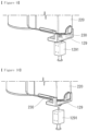
- the separating unit may include a separating member which protrudes inward from an inner side surface of the station.
- a coupling lever coupling the body cover of the cleaner to the dust bin may be caught by the separating unit and separated from the dust bin.
- the separating unit may be formed on the coupling body, and may include a transmission member disposed between the separating member and the coupling lever of the cleaner.
- One side of the transmission member may be disposed under the separating member, and other side of the transmission member may be disposed above the coupling lever of the cleaner.
- a lower part of the other side of the transmission member may maintain a contacted state with an upper side of the coupling lever of the cleaner.
- an upper part of the one side of the transmission member may contact the lower part of the separating member, and the other side of the transmission member may press the coupling lever downward to separate the body cover from the dust bin.
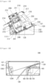
- the transmission member may include a vertical portion which connects the one side and the other side.
- a lower part of the vertical portion of the transmission member may include a step portion which is disposed adjacent to the separating member than an upper part
- the coupling body may include a coupling surface which forms the predetermined angle with the ground and to which a lower surface of the dust bin is coupled. When the coupling body is disposed horizontally with the ground, the separating member may be disposed under the coupling surface.
- the coupling body may include a coupling surface which forms the predetermined angle with the ground and to which a lower surface of the dust bin is coupled, and a guide part which is connected to the coupling surface and is formed in a shape corresponding to an outer surface of the dust bin.
- the separating unit may protrude inward from an inner side surface of the guide part.
- the dust removal system may include a cleaner including a suction unit, a suction motor which generates a suction force that sucks air along the suction unit, a dust separator which separates dust from air introduced through the suction unit, a dust bin which stores the dust separated from the dust separator, a body cover which selectively opens and closes a lower part of the dust bin, and a compression unit which moves an inner space of the dust bin and compresses the dust in the dust bin downward;
- the present invention may provide a station and a dust removal system having the same which is capable of removing the hassle of emptying a dust bin every time by a user
- the present invention may provide a station and a dust removal system having them same which is capable of preventing dust scattering occurred when a dust bin is emptied.
- the present invention may provide a station and a dust removal system having the same which is capable of removing the dust in a dust bin without a separate manipulation of a user and providing user convenience.
- the present invention may provide a station and a dust removal system having the same which is capable of simultaneously docking a stick vacuum cleaner and a robot cleaner to selectively remove the dust in the dust bin of the stick vacuum cleaner and the robot cleaner as needed.
- the present invention may provide a station and a dust removal system having the same which is capable of preventing residual dust from being remained in a dust bin and improving the suction power of a cleaner.
- the present invention may provide a station and a dust removal system having the same which is capable of preventing residue dust from remaining in a dust bin and removing odors generated by the residue.
- the singular form may include the plural form unless specifically stated in the phrase, and when described as "at least one (or more than one) of A, (and) B and C", it may contain one or more of all possible combinations of A, B and C.
- first, second, A, B, (a) and (b) may be used. These terms are only for distinguishing components from other components, and the natures, orders or sequences of the corresponding components are not limited by the terms.
- a component may be directly 'connected', 'coupled' or 'conjunction' to the other component or the component may be 'connected', 'coupled' or 'conjunction' to the other component by the way of another component between the component and the other component.
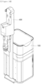
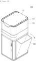
- the dust removal system 10 may include a station 100, a first cleaner 200, and a second cleaner 300. However, in one embodiment of the present invention some of these components may be excluded or additional components may be included,
- the dust removal system 10 may include a station 100.
- the first cleaner 200 and the second cleaner 300 may be disposed to the station 100.
- the first cleaner 200 may be coupled on the upper part of the station 100. Particularly, on the upper part of the station 100, the main body of the first cleaner 200 may be coupled.
- the second cleaner 300 may be coupled under the lower part of the station.
- the station 100 may remove the dust of the dust bin 215 of the first cleaner 200.
- the station 100 may remove the dust of the dust bin (unshown) of the second cleaner 300.
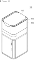
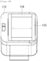
- the station 100 may include a housing 110.
- the housing 110 can form the exterior appearance of the station 100.
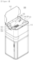
- a coupling body 120 on which the first cleaner 200 is coupled may be disposed on the upper part of the housing 110.
- the second cleaner 300 may be coupled under the lower part of the housing 110.
- a dust storage unit 130, a first flow path 140, a second flow path 150, a valve 160 and an inspirator 170 may be disposed inside the housing 110.
- the housing 110 is descried as being formed in a hexahedron shape as an example, but the shape of the housing 110 is not limited thereto, and the shape of the housing 110 may be variously changed.
- the housing 110 may include a first door member 112.
- the first door member 112 may be disposed on the upper surface of the housing 110.
- the first door member 112 may selectively expose to an outside the coupling body 120 disposed on the upper part of the housing 100.
- the first door member 112 may be opened when a user approaches the station 100, and the first door member 112 may be closed when the first cleaner 200 coupled on the station 100 is separated from the station 100. Accordingly, it is possible to prevent foreign matters such as dust from entering inside of the station 100.
- the housing 110 may include a first sensing unit 113.
- the first sensing unit 113 may be disposed on the housing 110.
- the first sensing unit 113 may detect whether a user approaches the station 100.
- the first sensing unit 113 may include a non-contact sensor.
- the first sensing unit 113 may include an infrared sensing unit (IR sensor).
- the first sensing unit 113 may include a contact sensor.
- the first sensing unit 113 may include a micro switch.
- the first sensing unit 113 is disposed on the upper surface of the housing as one example. However, the position of the first sensing unit 113 may be variously changed as long as it can detect whether a user approaches or not.
- the station 100 may include the coupling body 120.
- the coupling body 120 may be disposed on the upper part of the station 100.
- the coupling body 120 may be disposed on the upper part of the housing 110.
- the coupling body 120 may be selectively opened and closed by the first door member 112.
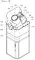
- the first cleaner 200 may be coupled on the coupling body 120.
- the main body 210 of the first cleaner 200 may be coupled on the coupling body 120.
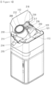
- the coupling body 120 may form a predetermined angle with a ground. Through this, when a user couples the main body 210 of the first cleaner 200 to the station 100, the main body 210 of the first cleaner 200 slides and couples to the coupling body 120 in a correct position.
- the predetermined angle of the coupling body 120 formed with the ground may be between 20 degrees and 30 degrees.
- the predetermined angle of the coupling body 120 formed with the ground is greater than 30 degrees, the inclination of the dust bin 215 is sever and there is a risk that the dust in the dust bin 215 remains due to gravity.
- the predetermined angle of the coupling body 120 formed with the ground is less than 20 degrees, it may not reach the static friction force between the lower surface of the dust bin 215 and the upper surface of the coupling body 120 and the dust bin 215 may not slide the coupling body 120.
- the dust bin 215 may not slide the coupling body 120 because it does not reach the static friction force between the lower surface of the dust bin 215 and the upper surface of the coupling body 120.
- the predetermined angle of the coupling body 120 formed with the ground may be between 23 degrees and 30 degrees. Considering the weight of the main body 210 of the first cleaner 200 and the average female body condition, if the predetermined angle of the coupling body 120 formed with the ground is less than 23 degrees, the user's wrist may be strained.
- the coupling body 120 may include a coupling surface 121.
- the coupling surface 121 may be disposed on the upper surface of the housing 110.
- the first cleaner 200 may be coupled on the coupling surface 121.
- the main body 210 of the first cleaner 200 may be coupled on the coupling surface 121.
- the dust bin 215 of the first cleaner 200 may be disposed on the coupling surface 121.
- the coupling surface 121 may form a predetermined angle with a ground.
- an angle formed by the coupling surface 121 with the ground may be an acute angle. Accordingly, it is convenient that the main body 210 of the first cleaner 200 is coupled on the coupling surface 121.
- the coupling between the coupling surface 121 and the main body 210 of the first cleaner 200 may mean a physical coupling in which the first cleaner 200 and the station 100 are coupled and fixed.
- the coupling body 120 may include a first guide part 122.
- the first guide part 122 may be disposed on the upper part of the housing 110.
- the first guide part 122 may be connected to the upper surface of the housing 110.
- the first guide part 122 may be connected to the coupling surface 121.
- the first guide part 122 may form a predetermined angle with the ground. For example, an angle formed by the first guide part 122 with the ground may be an obtuse angle.
- the first guide part 122 may be formed in a shape corresponding to the outer surface of the dust bin 215.
- the outer surface of the dust bin 215 may be coupled on the first guide part 122. Accordingly, there is convenience that the main body 210 of the first cleaner 200 is coupled on the coupling surface 121.
- the coupling body 120 may include a second guide part 123.
- the second guide part 123 may be disposed on the coupling surface 121.
- the second guide part 123 may protrude upward from the coupling surface 121.
- the second guide part 123 may include first and second guide members spaced apart from each other.
- the distance between the first guide member and the second guide member may correspond to the width of the main body 210 of the first cleaner 200.
- the distance between the first guide member and the second guide member may correspond to the width of the battery housing 220 of the first cleaner 200. Accordingly, there is convenience that the main body 210 of the first cleaner 200 is coupled on the coupling surface 121.
- the coupling body 120 may include a fixing part 124.
- the fixing part 124 may be disposed on the coupling surface 121.
- the fixing part 124 may be disposed on the second guide part 123.
- the fixing part 124 may fix the first cleaner 200 coupled on the coupling surface 121.
- the fixing part 124 may fix the main body 210 of the first cleaner 200 coupled on the coupling surface 121.
- the fixing part 124 may include a fixing member 129 fixing the main body 210 of the first cleaner 200 and a fifth driving unit 1291 for driving the fixing member 129.
- the fifth driving unit 1291 is described as an example of moving the fixing member 129 up and down, but as long as the main body 210 of the first cleaner 200 is fixed to the coupling body 120, the shape of the fixing member 129 and the type of the fifth driving unit 1291 may be variously changed.
- the fixing member 129 may be disposed on both sides of the bottom surface of the main body 210 of the first cleaner 200 coupled to the coupling body 120.
- the width of the fixing member 129 may correspond to the width of the main body 210 of the first cleaner 200 or may be smaller than the width of the main body 210 of the first cleaner 200.
- the fixing member 129 may be disposed on a second guide part 123. Specifically, referring to FIGS. 4 , 7 , 9 and 10 , the fixing member 129 may be disposed on a surface of the first and second guide members facing each other. Through this, the main body 210 of the first cleaner 200 guided by the second guide part 123 may be fixed in a correct position.
- the fifth driving unit 1291 is described as an example of moving the fixing member 129 up and down, but as long as the main body 210 of the first cleaner 200 is fixed to the coupling body 120, the shape of the fixing member 129 and the type of the fifth driving unit 1291 may be variously changed.
- the coupling body 120 may include a second sensing unit 125.
- the second sensing unit 125 may be disposed in the housing 110.
- the second sensing unit 125 may detect whether the first cleaner 200 is coupled on the coupling body 120.
- the second sensing unit 125 may face the main body 210 of the first cleaner 200.
- the second sensing unit 125 may include a non-contact sensor.
- the second sensing unit 125 may include an infrared sensor unit (IR sensor).
- the second sensing unit 125 may include a contact sensor.
- the second sensing unit 125 may include a micro switch.
- the opening and closing member 126 may be opened and closed based on a second rotation shaft 184 by a first driving unit (not shown).
- a first driving unit not shown
- the dust bin 215 of the first cleaner 200 and the first flow path 140 may be coupled in a flow path so that a fluid flows.
- the station 100 may include a first rotation shaft 181.
- the first rotation shaft 181 may be connected to the first driving unit.
- the first rotation shaft 181 may be interlocked with a first gear 182.
- the first rotation shaft 181 may rotate the first gear 182 in one direction or in other direction opposite to the one direction.
- the separating unit 128 may include the transmission member 1284.
- the transmission member 1284 may be formed on the coupling body 120.
- the transmission member 1284 may be formed on the coupling surface 121.
- the transmission member 1284 may rotate in one direction or the other direction like the coupling surface 121.
- the transmission member 1284 may be disposed between the separating member 1283 and the coupling lever 241 of the first cleaner 200. Specifically, one side of the transmission member 1284 may be disposed under the separating member 1283, and the other side of the transmission member 1284 may be disposed above the coupling lever 241. In this case, the other side of the transmission member 1284 may maintain a contacted state with the coupling lever 241 or may be maintained in a spaced state.
- the upper part or upper surface of one side of the transmission member 1284 may contact the lower part or lower surface of the separating member 1283.
- the other side of the transmission member 1284 may press the coupling lever 241 downward to separate the body cover 240 from the dust bin 215.
- the transmission member 1284 may include a vertical portion connecting one side and the other side.
- the vertical portion of the transmission member 1284 may extend in the vertical direction as shown in FIG. 13 .
- the vertical portion of the transmission member 1284 may include a step portion in which a lower part is disposed adjacent to the separating member 1283 than an upper part.
- the lower region of the vertical portion of the transmission member 1284 may be disposed adjacent to the separating member 1283 than the upper region of the vertical portion of the transmission member 1284.
- the body cover 240 Since the body cover 240 is separated from the dust bin 125 through the separating unit 128 in a state in which the bottom surface of the dust bin 215 is horizontal to the ground, the efficiency of collecting the inside of the dust bin 215 into the dust storage unit 130 by its own weight can be improved.
- the separating member 1283 is maintained in a fixed state. Unlike this, the separating member 1283 may be moved vertically through a second driving unit (not shown).
- the station 100 may include a dust storage unit 130.
- the dust storage unit 130 may be disposed in the housing 110.
- the dust storage unit 130 may be disposed under the coupling body 120. Accordingly, when the body cover 240 is separated from the dust bin 215, the dust in the dust bin 215 may be collected by the dust storage unit 130 by gravity.
- the station 100 may include a first flow path 140.
- the first flow path 140 may connect the dust bin 215 of the first cleaner 200 and the dust storage unit 130.
- the first flow path 140 may refer to a space between the dust bin 215 of the first cleaner 200 and the dust storage unit 130. Unlike Figure 2 , the first flow path 140 may mean a straight area extending vertically. The dust in the dust bin 215 of the first cleaner 200 may move to the dust storage unit 130 through the first flow path 140.
- the station 100 may include a second flow path 150.
- the second flow path 150 may connect the second cleaner 300 and the dust storage unit 130.
- the dust in the second cleaner 300 may move to the dust storage unit 130 through the second flow path 150.
- the station 100 may include a valve 160.
- the valve 160 may be disposed between the dust storage unit 130, the first flow path 140 and the second flow path 150.
- the valve 160 may selectively open and close the first flow path 140 and the second flow path 150 connected to the dust storage unit 130. Accordingly, it is possible to prevent the decrease in suction power caused by opening the plurality of flow paths 140 and 150.
- valve 160 may connect the first flow path 140 and the dust storage unit 130, and separate the second flow path 150 and the dust storage unit 130.
- valve 160 may separate the connection between the first flow path 140 and the dust storage unit 130, and connect the second flow path 150 and the dust storage unit 130.
- the station 100 may include an inspirator 170.
- the inspirator 170 may be disposed in the dust storage unit 130.
- the inspirator 170 may be disposed outside the dust storage unit 130 and may be connected to the dust storage unit 130.
- the inspirator 170 may generate suction power in the first flow path 140 and the second flow path 150. Accordingly, the inspirator 170 may provide a suction power capable of sucking the dust in the dust bin 215 of the first cleaner 200 and the dust in the second cleaner 300.
- the station 100 may include a charging unit (not shown).
- the charging unit may include a first charger (not shown) disposed on the coupling body 120.
- the first charger may be electrically connected to the first cleaner 200 coupling on the coupling body 120.
- the first charger may supply power to the battery of the first cleaner 200 coupled on the coupling body 120.
- the charging unit may include a second charger (not shown) disposed on the lower region of the housing 110.
- the second charger may be electrically connected to the second cleaner 300 coupled on the lower area of the housing 110.
- the second charger may supply power to the battery of the second cleaner 300 coupled on the lower area of the housing 110.
- the station 100 may include a side door (not shown).
- the side door may be disposed on the housing 110.
- the side door may selectively expose the dust storage unit 130 to an outside.
- a user since a user can use the dust storage unit 130 as a trash bin, user convenience can be improved. In addition, it allows a user to easily remove the dust storage unit 130 from the station 100.
- the dust removal system 10 may include a first cleaner 200.
- the first cleaner 200 may include a cleaner manually operated by a user.
- the first cleaner 200 may be a hand vacuum cleaner or a stick vacuum cleaner.
- the first cleaner 200 may be coupled over the station 100.
- the first cleaner 200 may be supported by the station 100.
- the first cleaner 200 may be coupled on the station 100.
- the first cleaner 200 may be coupled on the upper part of the housing 110.
- the main body 210 of the first cleaner 200 may be coupled on the coupling body 120.
- the dust in the dust bin 215 of the first cleaner 200 may be collected by gravity into the dust storage unit 130 of the station 100. Accordingly, since the dust in the dust bin can be removed without a separate manipulation of the user, user convenience can be provided. In addition, it is possible to eliminate the hassle of the user having to empty the dust bin every time. In addition, when the dust bin is emptied, it is possible to prevent the dust from scattering.
- the first cleaner 200 may include a main body 210.
- the main body 210 may include a suction motor 205.
- the main body 210 may be connected to an extension tube 280.
- the main body 210 may be connected to a cleaning module 290 through the extension tube 280.
- the main body 210 may generate a suction power through the suction motor 205 and may provide a suction power to the cleaning module 290 through the extension tube 280. External dust may flow into the main body 210 through the cleaning module 290 and the extension tube 280.
- a hinge 282 may be disposed on the extension tube 280. Specifically, at least a portion of the extension tube 280 may be rotated based on the hinge 282. Accordingly, when the main body 210 of the first cleaner 200 is coupled to the station 100, the extension tube 280 may support the main body 210.
- the main body 210 may include a suction unit 214.
- the suction unit 214 may protrude outward from the main body 210.
- the suction unit 214 may be formed in a cylindrical shape with an open inside.
- the suction unit 214 may communicate with the extension tube 280.
- the suction unit 214 may suck the air having dust.
- the suction unit 214 may be coupled on the coupling body 120. Specifically, the suction unit 214 may be coupled on the third guide part 217 of the coupling body 120.
- the main body 210 may include a dust separator 211.
- the dust separator 211 may communicate with the suction unit 214.
- the dust separator 211 may separate the dust sucked into the interior through the suction unit 214.
- the dust separator 211 may communicate with the dust bin 215.
- the dust separator 211 may separate dust by cyclone flow.
- the cyclone unit generating the cyclone flow may be disposed in at least one inside of the dust separator 211 and the dust bin 215.
- the cyclone unit may communicate with the suction unit 214.
- the air and dust sucked through the suction unit 214 spirally flow along the inner circumferential surface of the cyclone unit.
- the axis of the cyclone flow of the cyclone unit may extend in the vertical direction.
- the main body 210 may include a discharge cover 209 having an air discharge port 212 through which air is discharged from the suction motor 205.
- a HEPA filter for filtering air may be accommodated in the discharge cover 209.
- a flow guide may be disposed on the discharge cover 209. The flow guide may guide the flow of air discharged through the air discharge outlet 212.
- the first cleaner 200 may include a movement limiting part 217.
- the movement limiting part 217 may be disposed on the handle 216.
- the movement limiting part 217 may be disposed on one side of the handle 216 facing the main body 210.
- the movement limiting part 217 may serve to prevent the user's hand from moving in the longitudinal direction or the vertical direction of the handle 216.
- the movement limiting part 217 may be spaced apart from the extension part 218. That is, while holding the handle 216, some fingers of the user may be located above the movement limiting part 217, and the other fingers may be located below the movement limiting part 217.
- the movement limiting part 217 may be positioned between the index finger and the middle finger.
Landscapes
- Engineering & Computer Science (AREA)
- Mechanical Engineering (AREA)
- Robotics (AREA)
- Electric Vacuum Cleaner (AREA)
- Electric Suction Cleaners (AREA)
- Filters For Electric Vacuum Cleaners (AREA)
- Electrolytic Production Of Metals (AREA)
Claims (16)
- Station (100) à laquelle un dispositif de nettoyage (200) comportant un bac à poussière (215) et un couvercle de corps (240) ouvrant et fermant au choix une partie inférieure du bac à poussière (215) est couplé, comprenant :un corps de couplage (120) auquel le bac à poussière (215) est couplé et qui forme un angle prédéterminé avec le sol ;caractérisée en ce que la station (100) comprend en outre :une unité de séparation (128) qui sépare le couvercle de corps (240) du bac à poussière (215) ;une unité d'entraînement qui fait tourner le corps de couplage (120) horizontalement par rapport au sol ; etune unité de stockage de poussière (130) qui est disposée sous le corps de couplage (120).
- Station (100) selon la revendication 1, comprenant une unité de détection (125) qui détecte si le bac à poussière (215) est couplé au corps de couplage (120),
dans laquelle, lorsque le bac à poussière (215) est couplé au corps de couplage (120), l'unité d'entraînement fait tourner le corps de couplage (120) horizontalement par rapport au sol. - Station (100) selon la revendication 1, comprenant :un arbre de rotation (181) qui est relié à l'unité d'entraînement ;un premier engrenage (182) qui tourne en conjonction avec l'arbre de rotation (181) ; etun deuxième engrenage (183) qui est relié au corps de couplage (120) et est en prise avec le premier engrenage (182).
- Station (100) selon la revendication 3,dans laquelle, lorsque le premier engrenage (182) tourne dans une direction, le corps de couplage (120) tourne horizontalement par rapport au sol,lorsque le deuxième engrenage (183) tourne dans l'autre direction, le corps de couplage (120) tourne pour former l'angle prédéterminé avec le sol.
- Station (100) selon la revendication 1,
dans laquelle le corps de couplage (120) comporte une surface de couplage (121) qui forme l'angle prédéterminé avec le sol et à laquelle une surface inférieure du bac à poussière (215) est couplée, et un élément d'ouverture et de fermeture (126) qui est disposé sous le couvercle de corps (240) et ouvre et ferme au choix au moins une partie de la surface de couplage (121). - Station (100) selon la revendication 5, comprenant :un arbre de rotation (181) qui est relié à l'unité d'entraînement ;un premier engrenage (182) qui tourne en conjonction avec l'arbre de rotation (181) ; etun troisième engrenage (185) qui est relié à l'élément d'ouverture et de fermeture (126) et est en prise avec le premier engrenage (182).
- Station (100) selon la revendication 6,dans laquelle, lorsque le premier engrenage (182) tourne dans une direction, l'élément d'ouverture et de fermeture (126) tourne dans une direction formant l'angle prédéterminé avec la surface de couplage (121), etlorsque le premier engrenage (182) tourne dans l'autre direction, l'élément d'ouverture et de fermeture (126) tourne dans une direction horizontalement par rapport à la surface de couplage (121).
- Station (100) selon la revendication 7,
dans laquelle, lorsque le premier engrenage (182) tourne dans l'autre direction, l'élément d'ouverture et de fermeture (126) couple le couvercle de corps (240) au bac à poussière (215). - Station (100) selon la revendication 1,dans laquelle l'unité de séparation (128) comporte un élément de séparation (1283) qui fait saillie vers l'intérieur depuis une surface latérale intérieure de la station (100), etlorsque le corps de couplage (120) tourne dans une direction horizontalement par rapport au sol, un levier de couplage (241) couplant le couvercle de corps (240) du dispositif de nettoyage (200) au bac à poussière (215) est saisi par l'unité de séparation (128) et est séparé du bac à poussière (215).
- Station (100) selon la revendication 9,dans laquelle l'unité de séparation (128) est formée sur le corps de couplage (120) et comporte un élément de transmission (1284) disposé entre l'élément de séparation (1283) et le levier de couplage (241) du dispositif de nettoyage (200), etun côté de l'élément de transmission (1284) est disposé sous l'élément de séparation (1283), et l'autre côté de l'élément de transmission (1284) est disposé au-dessus du levier de couplage (241) du dispositif de nettoyage (200).
- Station (100) selon la revendication 10,dans laquelle une partie inférieure de l'autre côté de l'élément de transmission (1284) maintient un état en contact avec un côté supérieur du levier de couplage (241) du dispositif de nettoyage (200), etlorsque le corps de couplage (120) tourne dans une direction horizontale par rapport au sol, une partie supérieure d'un côté de l'élément de transmission (1284) entre en contact avec la partie inférieure de l'élément de séparation (1283), et l'autre côté de l'élément de transmission (1284) presse le levier de couplage (241) vers le bas pour séparer le couvercle de corps (240) du bac à poussière (215).
- Station (100) selon la revendication 10,
dans laquelle l'élément de transmission (1284) comporte une partie verticale qui relie un côté et l'autre côté. - Station (100) selon la revendication 12,
dans laquelle une partie inférieure de la partie verticale de l'élément de transmission (1284) comporte une partie étagée qui est disposée de manière adjacente à l'élément de séparation (1283) par rapport à une partie supérieure. - Station (100) selon la revendication 10,dans laquelle le corps de couplage (120) comporte une surface de couplage (121) qui forme l'angle prédéterminé avec le sol et à laquelle est couplée une surface inférieure du bac à poussière (215), etlorsque le corps de couplage (120) est disposé horizontalement par rapport au sol, l'élément de séparation (1283) est disposé sous la surface de couplage (121).
- Station (100) selon la revendication 1,dans laquelle le corps de couplage (120) comporte une surface de couplage (121) qui forme l'angle prédéterminé avec le sol et à laquelle une surface inférieure du bac à poussière (215) est couplée, et une partie de guidage (122) qui est reliée à la surface de couplage (121) et est formée en une forme correspondant à une surface extérieure du bac à poussière (215), etl'unité de séparation (128) fait saillie vers l'intérieur depuis une surface latérale intérieure de la partie de guidage (122).
- Système d'élimination de poussière comportant la station (100) selon l'une quelconque des revendications 1 à 15, comprenant en outre :
le dispositif de nettoyage (200) comportant une unité d'aspiration (214), un moteur d'aspiration (205) qui génère une force d'aspiration qui aspire de l'air le long de l'unité d'aspiration (214), un séparateur de poussière (211) qui sépare la poussière de l'air introduit à travers l'unité d'aspiration (214), un bac à poussière (215) qui stocke la poussière séparée du séparateur de poussière (211), un couvercle de corps (240) qui ouvre et ferme au choix une partie inférieure du bac à poussière (215), et une unité de compression (250) qui déplace un espace intérieur du bac à poussière (215) et comprime la poussière dans le bac à poussière (215) vers le bas.
Applications Claiming Priority (2)
| Application Number | Priority Date | Filing Date | Title |
|---|---|---|---|
| KR1020200046879A KR20210128786A (ko) | 2020-04-17 | 2020-04-17 | 스테이션 및 이를 포함하는 먼지 제거 시스템 |
| PCT/KR2021/004752 WO2021210930A1 (fr) | 2020-04-17 | 2021-04-15 | Station et système d'élimination de poussière le comprenant |
Publications (3)
| Publication Number | Publication Date |
|---|---|
| EP4137027A1 EP4137027A1 (fr) | 2023-02-22 |
| EP4137027A4 EP4137027A4 (fr) | 2024-05-15 |
| EP4137027B1 true EP4137027B1 (fr) | 2025-06-25 |
Family
ID=78085102
Family Applications (1)
| Application Number | Title | Priority Date | Filing Date |
|---|---|---|---|
| EP21789256.1A Active EP4137027B1 (fr) | 2020-04-17 | 2021-04-15 | Station et système d'élimination de poussière le comprenant |
Country Status (8)
| Country | Link |
|---|---|
| US (1) | US12543908B2 (fr) |
| EP (1) | EP4137027B1 (fr) |
| JP (1) | JP7459296B2 (fr) |
| KR (1) | KR20210128786A (fr) |
| CN (1) | CN115397294B (fr) |
| AU (1) | AU2021257363B2 (fr) |
| TW (1) | TWI792270B (fr) |
| WO (1) | WO2021210930A1 (fr) |
Families Citing this family (10)
| Publication number | Priority date | Publication date | Assignee | Title |
|---|---|---|---|---|
| KR102354485B1 (ko) | 2020-08-07 | 2022-01-21 | 삼성전자주식회사 | 진공 청소기와 도킹 스테이션을 포함하는 청소 장치 |
| EP4226832B1 (fr) * | 2020-10-08 | 2026-01-21 | LG Electronics Inc. | Station de dispositif de nettoyage |
| US20220287528A1 (en) * | 2021-03-11 | 2022-09-15 | Techtronic Cordless Gp | Vacuum cleaner docking station |
| WO2023153728A1 (fr) | 2022-02-10 | 2023-08-17 | 삼성전자 주식회사 | Support de charge à dispositif d'ouverture/fermeture automatique du couvercle et station de nettoyage associée |
| JP7627951B2 (ja) | 2022-03-08 | 2025-02-07 | アイリスオーヤマ株式会社 | 電気掃除機 |
| EP4434425A4 (fr) * | 2022-05-31 | 2025-10-22 | Samsung Electronics Co Ltd | Dispositif de station et procédé de fonctionnement de dispositif de station |
| US12390071B2 (en) * | 2022-12-07 | 2025-08-19 | Irobot Corporation | Evacuation station with debris separation |
| KR20240117378A (ko) * | 2023-01-25 | 2024-08-01 | 삼성전자주식회사 | 청소기 스테이션 |
| KR102868342B1 (ko) * | 2023-02-14 | 2025-10-13 | 엘지전자 주식회사 | 청소기 스테이션 |
| CN223009029U (zh) * | 2024-06-14 | 2025-06-24 | 东芝生活电器株式会社 | 电动吸尘器装置 |
Family Cites Families (43)
| Publication number | Priority date | Publication date | Assignee | Title |
|---|---|---|---|---|
| JP2002163382A (ja) * | 2000-11-29 | 2002-06-07 | Fujitsu Ltd | Aspサービスにおけるカストマイズ方法 |
| JP4205466B2 (ja) * | 2003-03-20 | 2009-01-07 | 日立アプライアンス株式会社 | 電気掃除機 |
| KR101199358B1 (ko) | 2005-07-18 | 2012-11-09 | 엘지전자 주식회사 | 로봇청소기의 먼지비움장치 |
| KR20070094288A (ko) * | 2006-03-17 | 2007-09-20 | 삼성전자주식회사 | 로봇청소기 시스템 |
| EP2027806A1 (fr) * | 2006-04-04 | 2009-02-25 | Samsung Electronics Co., Ltd. | Système robot nettoyeur doté d'un robot nettoyeur et d'une station d'accueil |
| KR20070104989A (ko) * | 2006-04-24 | 2007-10-30 | 삼성전자주식회사 | 로봇청소기 시스템 및 그 먼지제거 방법 |
| KR100788791B1 (ko) * | 2006-05-01 | 2008-01-02 | 주식회사 한울로보틱스 | 청소로봇의 청소동작 제어방법 |
| JP4939885B2 (ja) * | 2006-09-28 | 2012-05-30 | 株式会社東芝 | 電気掃除装置 |
| KR101204440B1 (ko) * | 2007-02-26 | 2012-11-26 | 삼성전자주식회사 | 로봇청소기와 도킹스테이션을 구비한 로봇청소기 시스템 |
| KR101330734B1 (ko) * | 2007-08-24 | 2013-11-20 | 삼성전자주식회사 | 로봇청소기와 도킹 스테이션을 구비하는 로봇청소기 시스템 |
| GB2478599B (en) * | 2010-03-12 | 2014-07-16 | Dyson Technology Ltd | A vacuum cleaning arrangement |
| KR101483541B1 (ko) * | 2010-07-15 | 2015-01-19 | 삼성전자주식회사 | 로봇청소기, 메인터넌스 스테이션 그리고 이들을 가지는 청소시스템 |
| DE102010038095B4 (de) * | 2010-10-11 | 2022-07-21 | Vorwerk & Co. Interholding Gmbh | Entleerungsstation für einen akkumulatorbetriebenen Elektrostaubsauger |
| KR101496913B1 (ko) | 2010-11-03 | 2015-03-02 | 삼성전자 주식회사 | 로봇청소기와 자동배출 스테이션 및 이를 가지는 로봇청소기 시스템 |
| JP5333633B1 (ja) | 2012-08-02 | 2013-11-06 | 三菱電機株式会社 | 電気掃除機 |
| GB2508034B (en) * | 2012-11-20 | 2015-10-07 | Dyson Technology Ltd | Cleaning appliance |
| CA2833555C (fr) * | 2013-11-18 | 2020-03-10 | Canplas Industries Ltd. | Aspirateur a main et ensemble de fixation assurant la connexion a un systeme d'aspiration central |
| US9788698B2 (en) | 2014-12-10 | 2017-10-17 | Irobot Corporation | Debris evacuation for cleaning robots |
| JP6786492B2 (ja) * | 2014-12-17 | 2020-11-18 | オマクロン・インテレクチュアル・プロパティ・インコーポレイテッドOmachron Intellectual Property Inc. | 表面クリーニング装置 |
| DE102014119191A1 (de) * | 2014-12-19 | 2016-06-23 | Vorwerk & Co. Interholding Gmbh | Basisstation für einen Staubsauger |
| DE102015103825A1 (de) * | 2015-03-16 | 2016-09-22 | Vorwerk & Co. Interholding Gmbh | Entleeren eines Staubraums eines Staubsaugers |
| JP6660738B2 (ja) * | 2016-01-12 | 2020-03-11 | 東芝ライフスタイル株式会社 | 電気掃除装置 |
| TWI653962B (zh) * | 2016-02-29 | 2019-03-21 | Lg電子股份有限公司 | 真空吸塵器 |
| JP2017158806A (ja) | 2016-03-09 | 2017-09-14 | 東芝ライフスタイル株式会社 | 電気掃除装置 |
| KR102560970B1 (ko) * | 2016-03-31 | 2023-07-31 | 엘지전자 주식회사 | 청소기 |
| JP6648618B2 (ja) * | 2016-04-14 | 2020-02-14 | 三菱電機株式会社 | ごみ回収装置、電気掃除機及び掃除機システム |
| WO2017196000A1 (fr) * | 2016-05-09 | 2017-11-16 | 엘지전자 주식회사 | Support pour aspirateur |
| KR102626405B1 (ko) * | 2016-05-09 | 2024-01-18 | 엘지전자 주식회사 | 청소기 충전대 |
| EP3323335B1 (fr) | 2016-11-17 | 2021-05-05 | Black & Decker Inc. | Dispositif de nettoyage |
| JP6820729B2 (ja) * | 2016-11-30 | 2021-01-27 | 東芝ライフスタイル株式会社 | 電気掃除装置 |
| US10464746B2 (en) * | 2016-12-28 | 2019-11-05 | Omachron Intellectual Property Inc. | Dust and allergen control for surface cleaning apparatus |
| JP2018196511A (ja) | 2017-05-23 | 2018-12-13 | 東芝ライフスタイル株式会社 | 電気掃除装置 |
| JP6933924B2 (ja) * | 2017-06-23 | 2021-09-08 | 東芝ライフスタイル株式会社 | 電気掃除装置 |
| KR102021922B1 (ko) | 2018-02-20 | 2019-09-17 | 엘지전자 주식회사 | 청소기 |
| WO2019180938A1 (fr) * | 2018-03-23 | 2019-09-26 | 三菱電機株式会社 | Soufflante électrique, dispositif de nettoyage électrique et dispositif de séchage à la main |
| KR102061513B1 (ko) * | 2018-08-30 | 2020-01-02 | 삼성전자주식회사 | 청소기 거치장치 및 이를 갖는 청소장치 |
| WO2020122631A1 (fr) * | 2018-12-14 | 2020-06-18 | 삼성전자주식회사 | Dispositif de nettoyage comprenant un aspirateur et une station d'accueil |
| KR20200073966A (ko) * | 2018-12-14 | 2020-06-24 | 삼성전자주식회사 | 진공 청소기와 도킹 스테이션을 포함하는 청소 장치 |
| EP3725206B1 (fr) * | 2019-04-18 | 2023-06-21 | Vorwerk & Co. Interholding GmbH | Procédé de fonctionnement d'un système de nettoyage, station de base et dispositif filtrant |
| US11998150B2 (en) * | 2019-05-01 | 2024-06-04 | Sharkninja Operating Llc | Vacuum cleaner and docking station for use with the same |
| DE102019004417A1 (de) * | 2019-06-25 | 2020-12-31 | Vorwerk & Co. Interholding Gmbh | Verfahren, Basisstation und Reinigungssystem zum Aussaugen eines Reinigungsgeräts |
| CN113317716A (zh) * | 2020-02-29 | 2021-08-31 | 无锡清易智慧科技有限公司 | 一种吸尘器泊接装置 |
| JP7498786B2 (ja) * | 2020-03-03 | 2024-06-12 | エルジー エレクトロニクス インコーポレイティド | 掃除機ステーション、掃除機システムおよび掃除機ステーションを制御する方法 |
-
2020
- 2020-04-17 KR KR1020200046879A patent/KR20210128786A/ko active Pending
-
2021
- 2021-04-15 CN CN202180029044.5A patent/CN115397294B/zh active Active
- 2021-04-15 AU AU2021257363A patent/AU2021257363B2/en active Active
- 2021-04-15 WO PCT/KR2021/004752 patent/WO2021210930A1/fr not_active Ceased
- 2021-04-15 US US17/919,378 patent/US12543908B2/en active Active
- 2021-04-15 EP EP21789256.1A patent/EP4137027B1/fr active Active
- 2021-04-15 JP JP2022562748A patent/JP7459296B2/ja active Active
- 2021-04-16 TW TW110113820A patent/TWI792270B/zh active
Also Published As
| Publication number | Publication date |
|---|---|
| JP7459296B2 (ja) | 2024-04-01 |
| EP4137027A4 (fr) | 2024-05-15 |
| JP2023523581A (ja) | 2023-06-06 |
| US12543908B2 (en) | 2026-02-10 |
| AU2021257363A1 (en) | 2022-12-22 |
| AU2021257363B2 (en) | 2024-02-15 |
| KR20210128786A (ko) | 2021-10-27 |
| WO2021210930A1 (fr) | 2021-10-21 |
| CN115397294B (zh) | 2023-12-26 |
| CN115397294A (zh) | 2022-11-25 |
| TW202139906A (zh) | 2021-11-01 |
| TWI792270B (zh) | 2023-02-11 |
| EP4137027A1 (fr) | 2023-02-22 |
| US20230172415A1 (en) | 2023-06-08 |
Similar Documents
| Publication | Publication Date | Title |
|---|---|---|
| EP4137027B1 (fr) | Station et système d'élimination de poussière le comprenant | |
| CN115443089B (zh) | 工作站和包括该工作站的除尘系统 | |
| TW202222240A (zh) | 清掃機系統 | |
| EP4265168A1 (fr) | Système de nettoyage | |
| US20240277197A1 (en) | Cleaner station and cleaner system | |
| KR102406189B1 (ko) | 청소기 시스템 | |
| CN117729870A (zh) | 吸尘器站 | |
| KR102527189B1 (ko) | 청소기 스테이션 및 이를 포함하는 청소기 시스템과, 청소기 시스템을 이용한 잔여 먼지 제거 방법 | |
| US20240277198A1 (en) | Cleaner station and cleaner system comprising the same | |
| US20250176774A1 (en) | Cleaner station | |
| KR20230133655A (ko) | 청소기 스테이션 | |
| KR102694203B1 (ko) | 청소기 | |
| EP4480373A1 (fr) | Station de dispositif de nettoyage | |
| EP4480372A1 (fr) | Station d'aspirateur | |
| US20260041294A1 (en) | Cleaner and cleaner system | |
| EP4356804A1 (fr) | Station d'aspirateur | |
| EP4736723A1 (fr) | Dispositif de nettoyage |
Legal Events
| Date | Code | Title | Description |
|---|---|---|---|
| STAA | Information on the status of an ep patent application or granted ep patent |
Free format text: STATUS: THE INTERNATIONAL PUBLICATION HAS BEEN MADE |
|
| PUAI | Public reference made under article 153(3) epc to a published international application that has entered the european phase |
Free format text: ORIGINAL CODE: 0009012 |
|
| STAA | Information on the status of an ep patent application or granted ep patent |
Free format text: STATUS: REQUEST FOR EXAMINATION WAS MADE |
|
| 17P | Request for examination filed |
Effective date: 20221116 |
|
| AK | Designated contracting states |
Kind code of ref document: A1 Designated state(s): AL AT BE BG CH CY CZ DE DK EE ES FI FR GB GR HR HU IE IS IT LI LT LU LV MC MK MT NL NO PL PT RO RS SE SI SK SM TR |
|
| DAV | Request for validation of the european patent (deleted) | ||
| DAX | Request for extension of the european patent (deleted) | ||
| A4 | Supplementary search report drawn up and despatched |
Effective date: 20240415 |
|
| RIC1 | Information provided on ipc code assigned before grant |
Ipc: A47L 9/10 20060101ALI20240409BHEP Ipc: A47L 9/28 20060101AFI20240409BHEP |
|
| GRAP | Despatch of communication of intention to grant a patent |
Free format text: ORIGINAL CODE: EPIDOSNIGR1 |
|
| STAA | Information on the status of an ep patent application or granted ep patent |
Free format text: STATUS: GRANT OF PATENT IS INTENDED |
|
| INTG | Intention to grant announced |
Effective date: 20250127 |
|
| GRAS | Grant fee paid |
Free format text: ORIGINAL CODE: EPIDOSNIGR3 |
|
| GRAA | (expected) grant |
Free format text: ORIGINAL CODE: 0009210 |
|
| STAA | Information on the status of an ep patent application or granted ep patent |
Free format text: STATUS: THE PATENT HAS BEEN GRANTED |
|
| AK | Designated contracting states |
Kind code of ref document: B1 Designated state(s): AL AT BE BG CH CY CZ DE DK EE ES FI FR GB GR HR HU IE IS IT LI LT LU LV MC MK MT NL NO PL PT RO RS SE SI SK SM TR |
|
| REG | Reference to a national code |
Ref country code: GB Ref legal event code: FG4D |
|
| REG | Reference to a national code |
Ref country code: CH Ref legal event code: EP |
|
| REG | Reference to a national code |
Ref country code: DE Ref legal event code: R096 Ref document number: 602021032964 Country of ref document: DE |
|
| REG | Reference to a national code |
Ref country code: CH Ref legal event code: EP |
|
| REG | Reference to a national code |
Ref country code: IE Ref legal event code: FG4D |
|
| PG25 | Lapsed in a contracting state [announced via postgrant information from national office to epo] |
Ref country code: FI Free format text: LAPSE BECAUSE OF FAILURE TO SUBMIT A TRANSLATION OF THE DESCRIPTION OR TO PAY THE FEE WITHIN THE PRESCRIBED TIME-LIMIT Effective date: 20250625 |
|
| REG | Reference to a national code |
Ref country code: LT Ref legal event code: MG9D |
|
| PG25 | Lapsed in a contracting state [announced via postgrant information from national office to epo] |
Ref country code: NO Free format text: LAPSE BECAUSE OF FAILURE TO SUBMIT A TRANSLATION OF THE DESCRIPTION OR TO PAY THE FEE WITHIN THE PRESCRIBED TIME-LIMIT Effective date: 20250925 Ref country code: GR Free format text: LAPSE BECAUSE OF FAILURE TO SUBMIT A TRANSLATION OF THE DESCRIPTION OR TO PAY THE FEE WITHIN THE PRESCRIBED TIME-LIMIT Effective date: 20250926 |
|
| PG25 | Lapsed in a contracting state [announced via postgrant information from national office to epo] |
Ref country code: BG Free format text: LAPSE BECAUSE OF FAILURE TO SUBMIT A TRANSLATION OF THE DESCRIPTION OR TO PAY THE FEE WITHIN THE PRESCRIBED TIME-LIMIT Effective date: 20250625 |
|
| PG25 | Lapsed in a contracting state [announced via postgrant information from national office to epo] |
Ref country code: HR Free format text: LAPSE BECAUSE OF FAILURE TO SUBMIT A TRANSLATION OF THE DESCRIPTION OR TO PAY THE FEE WITHIN THE PRESCRIBED TIME-LIMIT Effective date: 20250625 |
|
| PG25 | Lapsed in a contracting state [announced via postgrant information from national office to epo] |
Ref country code: RS Free format text: LAPSE BECAUSE OF FAILURE TO SUBMIT A TRANSLATION OF THE DESCRIPTION OR TO PAY THE FEE WITHIN THE PRESCRIBED TIME-LIMIT Effective date: 20250925 |
|
| PG25 | Lapsed in a contracting state [announced via postgrant information from national office to epo] |
Ref country code: LV Free format text: LAPSE BECAUSE OF FAILURE TO SUBMIT A TRANSLATION OF THE DESCRIPTION OR TO PAY THE FEE WITHIN THE PRESCRIBED TIME-LIMIT Effective date: 20250625 |
|
| REG | Reference to a national code |
Ref country code: NL Ref legal event code: MP Effective date: 20250625 |
|
| PG25 | Lapsed in a contracting state [announced via postgrant information from national office to epo] |
Ref country code: NL Free format text: LAPSE BECAUSE OF FAILURE TO SUBMIT A TRANSLATION OF THE DESCRIPTION OR TO PAY THE FEE WITHIN THE PRESCRIBED TIME-LIMIT Effective date: 20250625 |
|
| PG25 | Lapsed in a contracting state [announced via postgrant information from national office to epo] |
Ref country code: PT Free format text: LAPSE BECAUSE OF FAILURE TO SUBMIT A TRANSLATION OF THE DESCRIPTION OR TO PAY THE FEE WITHIN THE PRESCRIBED TIME-LIMIT Effective date: 20251027 |
|
| REG | Reference to a national code |
Ref country code: AT Ref legal event code: MK05 Ref document number: 1805568 Country of ref document: AT Kind code of ref document: T Effective date: 20250625 |
|
| PG25 | Lapsed in a contracting state [announced via postgrant information from national office to epo] |
Ref country code: IS Free format text: LAPSE BECAUSE OF FAILURE TO SUBMIT A TRANSLATION OF THE DESCRIPTION OR TO PAY THE FEE WITHIN THE PRESCRIBED TIME-LIMIT Effective date: 20251025 |
|
| PG25 | Lapsed in a contracting state [announced via postgrant information from national office to epo] |
Ref country code: AT Free format text: LAPSE BECAUSE OF FAILURE TO SUBMIT A TRANSLATION OF THE DESCRIPTION OR TO PAY THE FEE WITHIN THE PRESCRIBED TIME-LIMIT Effective date: 20250625 Ref country code: SM Free format text: LAPSE BECAUSE OF FAILURE TO SUBMIT A TRANSLATION OF THE DESCRIPTION OR TO PAY THE FEE WITHIN THE PRESCRIBED TIME-LIMIT Effective date: 20250625 |
|
| PG25 | Lapsed in a contracting state [announced via postgrant information from national office to epo] |
Ref country code: CZ Free format text: LAPSE BECAUSE OF FAILURE TO SUBMIT A TRANSLATION OF THE DESCRIPTION OR TO PAY THE FEE WITHIN THE PRESCRIBED TIME-LIMIT Effective date: 20250625 |
|
| PG25 | Lapsed in a contracting state [announced via postgrant information from national office to epo] |
Ref country code: PL Free format text: LAPSE BECAUSE OF FAILURE TO SUBMIT A TRANSLATION OF THE DESCRIPTION OR TO PAY THE FEE WITHIN THE PRESCRIBED TIME-LIMIT Effective date: 20250625 |
|
| PG25 | Lapsed in a contracting state [announced via postgrant information from national office to epo] |
Ref country code: EE Free format text: LAPSE BECAUSE OF FAILURE TO SUBMIT A TRANSLATION OF THE DESCRIPTION OR TO PAY THE FEE WITHIN THE PRESCRIBED TIME-LIMIT Effective date: 20250625 |
|
| PG25 | Lapsed in a contracting state [announced via postgrant information from national office to epo] |
Ref country code: SK Free format text: LAPSE BECAUSE OF FAILURE TO SUBMIT A TRANSLATION OF THE DESCRIPTION OR TO PAY THE FEE WITHIN THE PRESCRIBED TIME-LIMIT Effective date: 20250625 |
|
| PG25 | Lapsed in a contracting state [announced via postgrant information from national office to epo] |
Ref country code: ES Free format text: LAPSE BECAUSE OF FAILURE TO SUBMIT A TRANSLATION OF THE DESCRIPTION OR TO PAY THE FEE WITHIN THE PRESCRIBED TIME-LIMIT Effective date: 20250625 |
|
| PG25 | Lapsed in a contracting state [announced via postgrant information from national office to epo] |
Ref country code: DK Free format text: LAPSE BECAUSE OF FAILURE TO SUBMIT A TRANSLATION OF THE DESCRIPTION OR TO PAY THE FEE WITHIN THE PRESCRIBED TIME-LIMIT Effective date: 20250625 |
|
| PG25 | Lapsed in a contracting state [announced via postgrant information from national office to epo] |
Ref country code: IT Free format text: LAPSE BECAUSE OF FAILURE TO SUBMIT A TRANSLATION OF THE DESCRIPTION OR TO PAY THE FEE WITHIN THE PRESCRIBED TIME-LIMIT Effective date: 20250625 |
|
| PLBE | No opposition filed within time limit |
Free format text: ORIGINAL CODE: 0009261 |
|
| STAA | Information on the status of an ep patent application or granted ep patent |
Free format text: STATUS: NO OPPOSITION FILED WITHIN TIME LIMIT |