EP4137039A1 - Émetteur de connexion avec lames de connexion - Google Patents
Émetteur de connexion avec lames de connexion Download PDFInfo
- Publication number
- EP4137039A1 EP4137039A1 EP21306130.2A EP21306130A EP4137039A1 EP 4137039 A1 EP4137039 A1 EP 4137039A1 EP 21306130 A EP21306130 A EP 21306130A EP 4137039 A1 EP4137039 A1 EP 4137039A1
- Authority
- EP
- European Patent Office
- Prior art keywords
- connection
- guidewire
- longitudinal
- transversal
- connecting element
- Prior art date
- Legal status (The legal status is an assumption and is not a legal conclusion. Google has not performed a legal analysis and makes no representation as to the accuracy of the status listed.)
- Granted
Links
Images



Classifications
-
- A—HUMAN NECESSITIES
- A61—MEDICAL OR VETERINARY SCIENCE; HYGIENE
- A61B—DIAGNOSIS; SURGERY; IDENTIFICATION
- A61B5/00—Measuring for diagnostic purposes; Identification of persons
- A61B5/68—Arrangements of detecting, measuring or recording means, e.g. sensors, in relation to patient
- A61B5/6846—Arrangements of detecting, measuring or recording means, e.g. sensors, in relation to patient specially adapted to be brought in contact with an internal body part, i.e. invasive
- A61B5/6847—Arrangements of detecting, measuring or recording means, e.g. sensors, in relation to patient specially adapted to be brought in contact with an internal body part, i.e. invasive mounted on an invasive device
- A61B5/6851—Guide wires
-
- A—HUMAN NECESSITIES
- A61—MEDICAL OR VETERINARY SCIENCE; HYGIENE
- A61B—DIAGNOSIS; SURGERY; IDENTIFICATION
- A61B2562/00—Details of sensors; Constructional details of sensor housings or probes; Accessories for sensors
- A61B2562/22—Arrangements of medical sensors with cables or leads; Connectors or couplings specifically adapted for medical sensors
- A61B2562/225—Connectors or couplings
- A61B2562/227—Sensors with electrical connectors
-
- A—HUMAN NECESSITIES
- A61—MEDICAL OR VETERINARY SCIENCE; HYGIENE
- A61M—DEVICES FOR INTRODUCING MEDIA INTO, OR ONTO, THE BODY; DEVICES FOR TRANSDUCING BODY MEDIA OR FOR TAKING MEDIA FROM THE BODY; DEVICES FOR PRODUCING OR ENDING SLEEP OR STUPOR
- A61M25/00—Catheters; Hollow probes
- A61M25/01—Introducing, guiding, advancing, emplacing or holding catheters
- A61M25/09—Guide wires
-
- H—ELECTRICITY
- H01—ELECTRIC ELEMENTS
- H01R—ELECTRICALLY-CONDUCTIVE CONNECTIONS; STRUCTURAL ASSOCIATIONS OF A PLURALITY OF MUTUALLY-INSULATED ELECTRICAL CONNECTING ELEMENTS; COUPLING DEVICES; CURRENT COLLECTORS
- H01R12/00—Structural associations of a plurality of mutually-insulated electrical connecting elements, specially adapted for printed circuits, e.g. printed circuit boards [PCB], flat or ribbon cables, or like generally planar structures, e.g. terminal strips, terminal blocks; Coupling devices specially adapted for printed circuits, flat or ribbon cables, or like generally planar structures; Terminals specially adapted for contact with, or insertion into, printed circuits, flat or ribbon cables, or like generally planar structures
- H01R12/70—Coupling devices
- H01R12/71—Coupling devices for rigid printing circuits or like structures
- H01R12/712—Coupling devices for rigid printing circuits or like structures co-operating with the surface of the printed circuit or with a coupling device exclusively provided on the surface of the printed circuit
- H01R12/716—Coupling device provided on the PCB
- H01R12/718—Contact members provided on the PCB without an insulating housing
-
- H—ELECTRICITY
- H01—ELECTRIC ELEMENTS
- H01R—ELECTRICALLY-CONDUCTIVE CONNECTIONS; STRUCTURAL ASSOCIATIONS OF A PLURALITY OF MUTUALLY-INSULATED ELECTRICAL CONNECTING ELEMENTS; COUPLING DEVICES; CURRENT COLLECTORS
- H01R12/00—Structural associations of a plurality of mutually-insulated electrical connecting elements, specially adapted for printed circuits, e.g. printed circuit boards [PCB], flat or ribbon cables, or like generally planar structures, e.g. terminal strips, terminal blocks; Coupling devices specially adapted for printed circuits, flat or ribbon cables, or like generally planar structures; Terminals specially adapted for contact with, or insertion into, printed circuits, flat or ribbon cables, or like generally planar structures
- H01R12/70—Coupling devices
- H01R12/71—Coupling devices for rigid printing circuits or like structures
- H01R12/75—Coupling devices for rigid printing circuits or like structures connecting to cables except for flat or ribbon cables
-
- H—ELECTRICITY
- H01—ELECTRIC ELEMENTS
- H01R—ELECTRICALLY-CONDUCTIVE CONNECTIONS; STRUCTURAL ASSOCIATIONS OF A PLURALITY OF MUTUALLY-INSULATED ELECTRICAL CONNECTING ELEMENTS; COUPLING DEVICES; CURRENT COLLECTORS
- H01R12/00—Structural associations of a plurality of mutually-insulated electrical connecting elements, specially adapted for printed circuits, e.g. printed circuit boards [PCB], flat or ribbon cables, or like generally planar structures, e.g. terminal strips, terminal blocks; Coupling devices specially adapted for printed circuits, flat or ribbon cables, or like generally planar structures; Terminals specially adapted for contact with, or insertion into, printed circuits, flat or ribbon cables, or like generally planar structures
- H01R12/70—Coupling devices
- H01R12/82—Coupling devices connected with low or zero insertion force
- H01R12/85—Coupling devices connected with low or zero insertion force contact pressure producing means, contacts activated after insertion of printed circuits or like structures
- H01R12/89—Coupling devices connected with low or zero insertion force contact pressure producing means, contacts activated after insertion of printed circuits or like structures acting manually by moving connector housing parts linearly, e.g. slider
-
- H—ELECTRICITY
- H01—ELECTRIC ELEMENTS
- H01R—ELECTRICALLY-CONDUCTIVE CONNECTIONS; STRUCTURAL ASSOCIATIONS OF A PLURALITY OF MUTUALLY-INSULATED ELECTRICAL CONNECTING ELEMENTS; COUPLING DEVICES; CURRENT COLLECTORS
- H01R13/00—Details of coupling devices of the kinds covered by groups H01R12/70 or H01R24/00 - H01R33/00
- H01R13/02—Contact members
- H01R13/10—Sockets for co-operation with pins or blades
- H01R13/11—Resilient sockets
- H01R13/112—Resilient sockets forked sockets having two legs
Definitions
- the present invention relates to safely connecting a guidewire to a connector, for example a circuit board assembly.
- Guidewire assemblies comprising guidewire with a sensor mounted at its distal tip are routinely used in intravascular imaging.
- the sensor of the distal tip of the guidewire is usually connected to an interface cable, connecting to external equipment such as for example monitors, control units or computers.
- Blockages of blood vessels may occur in various parts of an animal (e.g., a human or a non-human animal) and may have significant repercussions.
- a blood clot In an ischemic stroke, for example, a blood clot fully or partially blocks blood flow in a cerebral artery. If the clot is not treated quickly, insufficient blood flow may cause irreparable damage to the brain.
- Blockages may be caused by blood clots, which may be caused by coagulation of red and/or white blood cells and/or platelets within a blood vessel.
- the coagulation may be triggered by a variety of factors, including an injury, abnormal blood flow at the site of the blockage, a disease/condition predisposing an animal to coagulation, and/or other factors.
- a common treatment of a clot is chemical dissolution of the clot, which is feasible within the first 4.5 hours following blockage of a blood vessel.
- Another common option is mechanical thrombectomy, in which an aspiration catheter or a stent-retriever is used to remove the blood clot from the blood vessel.
- Stent-retrievers include a stent attached at the end of a wire.
- the stent is deployed into the vasculature and into the clot, expanded into the clot, and, after a typical waiting time of 0.5 to 10 minutes, extracted to pull the clot out of the blood vessel. Due to non-optimal grabbing of the clot by the stent-retriever, some parts of the clot may be left by or be lost from the retriever, such that several succession treatments (an average 3 times) may be necessary to treat the blockage and restore circulation in the vessel.
- An early determination of the nature of the clot, performed using a guidewire as describe above, may result in an enhanced treatment of said clot.
- a known technique for determining the nature of the clot includes applying the sensor assembly of the guidewire to the clot, in order to measure an evolution of the clot impedance over a predetermined frequency range.
- the corresponding electrical signals are conveyed along the length of the guidewire, which is connected, at its proximal end, to a processing unit, through a connection transmitter.
- connection transmitter comprises a series of electrical contacts arranged along a longitudinal axis. The proximal end of the guidewire is inserted along said longitudinal axis, until each electrical contact of the connection transmitter is in electrical contact with a corresponding guidewire contact, said guidewire contacts being successively arranged along a longitudinal direction of the guidewire, at a distance from each other.
- a purpose of the invention is to provide a connection transmitter that is easier to use than the known connection transmitters, while reducing the risks of deterioration of the guidewire.
- connection transmitter aimed at connecting a guidewire to a connector assembly, the connection transmitter comprising:
- this solution achieves the above objective.
- it allows the obtaining of a reduction of the wearing of the connection blades and further of a reduced homogeneous wear of said blade while providing an easy and handy connection device.
- connection transmitter according to the invention may include one or more of the following characteristics, taken in isolation from one another or in combination with one another:
- connection kit comprising a connection transmitter according to any one of the hare above listed technical features, and a guidewire aimed at being introduced at least partially inside the connection transmitter.
- connection kit according to the invention may include one or more of the following characteristics, taken in isolation from one another or in combination with one another:
- connection process aimed at connecting a guidewire to a connector assembly of a connection transmitter, the connection process being implemented by means of a connection transmitter according to any one the hereabove listed technical features, said connection process comprising following steps in the order of enunciation:
- the process according to the present invention may comprise a step before the introduction of the guidewire inside the longitudinal connecting element, said additional step being the switching of the connection transmitter into its non-connecting configuration.
- connection transmitter 10 aimed at connecting a guidewire 12 to a connector assembly 14, for example a printed circuit board assembly.
- the connection transmitter 10 is aimed at being handled by a health professional during operation of the guidewire 12.
- a guidewire 12 is a wire or spring used as a guide for placement of a larger device or prosthesis, such as a catheter or intramedullary pin, inside a patient's body.
- the guidewire may also be used to probe tissues of a patient, such as tissues surrounding a clot or the clot itself.
- the present invention is about connecting a guidewire 12 of about 0,2 to 0,5mm, preferably 0,35mm.
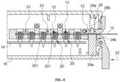
- the guidewire 12 comprises at least one circumferential contact zone 13 (see figures 5b and 8 ) arranged along a longitudinal direction of the guidewire. Those contact zones are aimed at establishing a connection with the connector assembly 14.
- connection transmitter 10 comprises:
- the casing 16 surrounds at least partially the connector assembly 14.
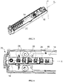
- the casing displays a general cylindric shape, as can be seen on figure 1 .
- the casing 16 comprises two parts fixed together, for instance screwed together around the connector assembly 14.
- the casing 16 displays one opening 16a at one of its longitudinal extremities, said opening 16a receiving the longitudinal connecting element 18.
- the material used for the casing 16 comprises a resin manufactured by FormLabs ® : White Resin Standard. It is an ABS-like resin usually used for stereolithography printing.
- the casing 16 presents a length comprised between 140 and 150 mm, preferably 148.5 mm and a diameter comprised between 25 and 30 mm, preferably 28 mm.
- the casing 16 is a removable casing.
- the connector assembly may be, as illustrated in figure 6 , a board assembly, and more precisely a printed circuit board assembly (PCBA).
- PCBA printed circuit board assembly
- the size of the connector assembly 14 is dependent on the components used to be functional.
- the shape of the connector assembly 14 is designed according to the guidewire 12 to be connected.
- the connector assembly 14 comprises at least one connection blade 20 extending along a transversal axis Y. Each blade 20 is aimed at being put in contact with one corresponding contact zone 13 of the guidewire 12, in order to establish an electrical connection.
- the transversal axis Y is sensibly perpendicular to the longitudinal axis X.
- Each connecting blade 20 presents a width comprised between 2 and 3 mm, preferably 2,6 mm and a height comprised between 6 and 8 mm, preferably 7,5 mm.
- each connection blade 20 comprises at least one finger 201 at its free end.
- the finger may display a general "C" shaped portion either it the extremity of the finger 201 or at its end.
- the guidewire 12 can cross said C shaped section.
- each finger 201 is simply slightly inclinable and bends under the pressure force exerted by and/or the weight of the guidewire put in contact with it.
- the finger 201 could also be provided, on its extremity, with a platform aimed at connecting the guidewire 12.
- each connection blade 20 displays a general comb shape with four fingers 201.
- each finger 201 presents a bending in one or the other radial direction.
- the bending of the fingers 201 alternates along the longitudinally X axis.
- Those bent fingers 201 thus generate a general V shape of the free ends of each blade 20 which creates a funnel for an introduced guidewire 12.
- the blades 20 preferably comprise some kind of copper-beryllium alloy (Cu Be) and are further coated with Nickel (Ni) and Gold (Au) to enhance their electrical properties.
- Cu Be copper-beryllium alloy
- Ni Nickel
- Au Gold
- the connector assembly 14 comprises six connection blades 20 extending along the transversal axis Y.
- the six connection blades 20 are aligned along the longitudinal X axis, aligned with the longitudinal connecting element 18 (see figures 2 and 3 ). More generally, the number of connection blades 20 is at least equal to the number of contact zones 13 of the guidewire with which the connection transmitter 10 is meant to cooperate.
- the longitudinal connecting element 18 presents a length comprised between 30 and 50 mm, preferably 42 mm.
- the longitudinal connecting element 18 is translatable, within the casing 16, through the opening 16a, along the transversal axis Y.
- the connecting element 18 is longitudinally secured to the casing in order to avoid any unwanted longitudinal sliding along the X axis, as will be later described.
- the connecting element 18 can only translate transversally along the Y axis.
- the longitudinal connecting element 18 is aimed at receiving a guidewire 12. More precisely, as can be seen on figures 5a and 5c , the longitudinal connecting element 18 comprises a longitudinal cavity 22 extending along the longitudinal axis X. In those embodiments, this longitudinal cavity 22 is aimed at receiving the guidewire 12.
- the longitudinal connecting element 18 is specifically designed to avoid radial or transversal sliding of the guidewire 12 once it is introduced in it. More precisely, the longitudinal connecting element 18 only allows the longitudinal sliding of the guidewire 12, as can be deduced from figures 5a, 5b , 5c , 7a, 7b, 7c and 8 .
- the longitudinal connecting element 18 comprises at least one radial stop 23.
- the radial stop 23 is the wall of the longitudinal cavity 22 itself. In some alternative not represented embodiment, the radial stop 23 might be a set of internal teeth or spikes or a specific external wall texture.
- the longitudinal connecting element 18 and the casing 16 both comprise wire longitudinal locking elements 24 aimed at cooperating together when activated.
- said wire longitudinal locking means comprise a locking block 24a secured to the casing 16 while the longitudinal connecting element 18 presents a corresponding transversal locking cavity 24b.
- locking block 24a can be a soft polymer (PDMS) block.
- Said transversal locking cavity 24b opens inside the longitudinal cavity 22 of the longitudinal connecting element 18.
- the transversal locking cavity 24b is stationary with regards to the longitudinal connecting element 18. This way, the transversal locking cavity 24b is preferably transversally mobile with respect to the polymer locking block 24a.
- the polymer locking block 24a may be protruding inside the longitudinal cavity 22 of the longitudinal connecting element 18 and obturate it (see figures 7c and 8 ) or remain outside said longitudinal cavity 22 (see figures 7a, 7b ). In its protruding position the polymer locking block 24a may cooperate by friction with the introduced guidewire 12, thus preventing it from sliding along the X axis.
- the longitudinal connecting element 18 further comprises a longitudinal registration element, for instance a distal wall of the longitudinal cavity 22.
- the longitudinal registration element is designed so that, when the distal tip the guidewire 12 rests against said longitudinal registration element, each contact zone 13 of the guidewire 12 is located in a respective transversal cavity 26 of the longitudinal connecting element 18. Said transversal cavities 26 will be described below.
- the longitudinal connecting element 18 further comprises at least one transversal cavity 26 extending along the Y axis. This at least one transversal cavity 26 is aimed at cooperating, by transversal translation, with the at least one connection blade 20 of the connector assembly 14.
- the number of connection blades 20 is preferably the same as the number of transversal cavities 26. This way, each connection blade 20 corresponds to one corresponding transversal cavity 26.
- the longitudinal connecting element 18 comprises six transversal cavities 26, each transversal cavity 26 corresponding to a connecting blade 20 with which it is aimed to cooperate. Each cavity presents two openings along the Y axis, on each surface of the longitudinal connecting element 18.
- each transversal cavity 26 presents only one opening on the surface facing the connector assembly 14.
- the transversal cavities are preferably square shaped.
- the size of each transversal cavity 26 is comprised between 2 and 5mm length or width. In case the transversal cavities 26 are squares, they preferably measure 4mm width and 4mm length, meaning that, when connected to the guidewire 12, each transversal cavity 26 extends 2mm on each side of the guidewire 12, each half transversal cavity 26 having a width of 2mm and a length of 4mm.
- the longitudinal cavity 22 of the longitudinal connecting element 18 intersects each of its transversal cavity 26 (see figure 5c ). This means that a guidewire 12 introduced into the longitudinal cavity 22 of the longitudinal connecting element 18 may crosse each of the transversal cavities 26 of the longitudinal connecting element 18 as illustrated on figures 5c , 7c and 8 .
- connection transmitter 10 presents at least two configurations:
- connection transmitter 10 The configuration of the connection transmitter 10 is changed by translating transversally (along the Y axis) the longitudinal connecting element 18 within the casing 16.
- the transversal cavities 26 of the longitudinal connecting element 18 and the connection blades 20 of the connector assembly 14 are positioned in two distinct planes, with respect to the transversal axis Y.
- the transversal cavities 26 of the longitudinal connecting element 18 and the connection blades 20 of the connector assembly 14 are positioned in the same plane, regarding the transversal axis Y, leading to a transversal cooperation by engagement, at least partially.
- the guidewire 12 is put in contact with at least one of the connecting blades 20 of the connector assembly 14, as the blades 20 fill the space within the transversal cavities 26 crossed by the guidewire 12.
- the connecting configuration enables to connect the guidewire 12 introduced inside the longitudinal connecting element 18, and more specifically the contact zones 13, with the connection blades 20 of the connector assembly 14. This is illustrated on figure 8 .
- the polymer locking block 24a secures the guidewire 12 thanks to friction.
- the polymer locking block 24a has a further purpose: preventing a user to insert the guidewire 12 without activating the longitudinal connecting element 18 and sliding it into the non-connecting configuration in which the connection blades 20 are disengaged from the transversal cavities 26. This protects the connecting blades 20 that could be damaged if a lateral stress is applied to them by forcing a wire among them longitudinally ( i.e., along the longitudinal axis X) instead of transversally.
- connection system One of the main issues of any kind of connection system is the wear of the connecting elements, in particular the asymmetrical wearing of said elements.
- the connecting configuration of the connection transmitter 10 enables to connect any guidewire 12 introduced inside the longitudinal connecting element 18, with each connection blade 20 at the same time. This is made possible by the transversal translation movement of the longitudinal connecting element 18 within the casing 16.
- the wire longitudinal locking elements 24 cooperate together when the connection transmitter 10 is in its connecting configuration in order to avoid any longitudinal sliding of the introduced guidewire 12.
- the default, or resting configuration of the longitudinal connecting element 18 is the connecting configuration. In some not represented alternative embodiment, the default or resting configuration could be the non-connecting configuration.
- the default/resting configuration is maintained by means of a transversal locking element 28 secured to the longitudinal connecting element 18 and aimed at transversally cooperating with the casing 16.
- the transversal locking element 28 comprises a spring extending between the casing 16 and the longitudinal connecting element 28, thus continually pushing the connecting element 18 towards the casing 16, in a downwards way.
- the spring is axially locked by means of two pawns 28a, 28b (see figure 8 ).
- the spring in order to deactivate the transversal locking element 28, the spring has to be activated/compressed. Therefore, in those embodiments, when the spring is activated/compressed, the transversal locking element 28 is deactivated/unlocked and the connection transmitter 10 is in its non-connecting configuration. More precisely, when the locking element 28 is deactivated/unlocked, the connecting element 28 can be pushed upwards to the other half of the casing 16. In an alternative embodiment, when said spring is activated/compressed, the transversal locking element 28 is deactivated/unlocked and the connection transmitter 10 is in its connecting configuration.
- the longitudinal connecting element 18 comprises an activation switch 30, said activation switch 30 being operable from outside the casing. More precisely, the activation switch 30 enables to deactivate/unlock the transversal locking element 28 and thus enabling the longitudinal connecting element 18 to translate transversally (along the Y axis), thus leading to a configuration change.
- the activation switch 30 comprises a slider 32 which is aimed at being activated with a user's thumb. The slider 32 is secured to the connecting element 18. The slider 32 cooperates with the casing 16, particularly the downside of the casing 16 by means of sliding elements 34.
- the sliding elements 34 may comprise at least one tab 34a located on one of the slider 32 and the casing 16 (for instance at the opening 16a), and at least one corresponding transversal groove 34b located on the other one of the casing 16 and the slider 32, depending on the embodiment.
- Each tab 34a is aimed at sliding inside its corresponding transversal groove 34b, thus allowing the slider 32 to slide transversally with regards to the casing 16, and thus allowing the connected element 18 to slide transversally inside the casing 16.
- connection transmitter 10 enables to implement a connection process aimed at connecting a guidewire 12 to a connector assembly 14 of said connection transmitter 10.
- the connection process comprises following steps in the order of enunciation:
- the first step would not exist.
Landscapes
- Life Sciences & Earth Sciences (AREA)
- Health & Medical Sciences (AREA)
- Medical Informatics (AREA)
- Molecular Biology (AREA)
- Pathology (AREA)
- Engineering & Computer Science (AREA)
- Biomedical Technology (AREA)
- Heart & Thoracic Surgery (AREA)
- Physics & Mathematics (AREA)
- Biophysics (AREA)
- Surgery (AREA)
- Animal Behavior & Ethology (AREA)
- General Health & Medical Sciences (AREA)
- Public Health (AREA)
- Veterinary Medicine (AREA)
- Media Introduction/Drainage Providing Device (AREA)
- Surgical Instruments (AREA)
- Details Of Connecting Devices For Male And Female Coupling (AREA)
Priority Applications (6)
| Application Number | Priority Date | Filing Date | Title |
|---|---|---|---|
| EP21306130.2A EP4137039B1 (fr) | 2021-08-20 | 2021-08-20 | Émetteur de connexion avec lames de connexion |
| ES21306130T ES2985203T3 (es) | 2021-08-20 | 2021-08-20 | Transmisor de conexión con hojas de conexión |
| JP2024510223A JP2024530703A (ja) | 2021-08-20 | 2022-08-12 | 接続ブレードを備えた接続トランスミッタ |
| PCT/EP2022/072669 WO2023020961A1 (fr) | 2021-08-20 | 2022-08-12 | Transmetteur de connexion avec lames de connexion |
| US18/684,774 US20240350089A1 (en) | 2021-08-20 | 2022-08-12 | Connection transmitter with connection blades |
| CN202280056737.8A CN117835897A (zh) | 2021-08-20 | 2022-08-12 | 带连接片的连接传送器 |
Applications Claiming Priority (1)
| Application Number | Priority Date | Filing Date | Title |
|---|---|---|---|
| EP21306130.2A EP4137039B1 (fr) | 2021-08-20 | 2021-08-20 | Émetteur de connexion avec lames de connexion |
Publications (3)
| Publication Number | Publication Date |
|---|---|
| EP4137039A1 true EP4137039A1 (fr) | 2023-02-22 |
| EP4137039C0 EP4137039C0 (fr) | 2024-03-27 |
| EP4137039B1 EP4137039B1 (fr) | 2024-03-27 |
Family
ID=77666443
Family Applications (1)
| Application Number | Title | Priority Date | Filing Date |
|---|---|---|---|
| EP21306130.2A Active EP4137039B1 (fr) | 2021-08-20 | 2021-08-20 | Émetteur de connexion avec lames de connexion |
Country Status (6)
| Country | Link |
|---|---|
| US (1) | US20240350089A1 (fr) |
| EP (1) | EP4137039B1 (fr) |
| JP (1) | JP2024530703A (fr) |
| CN (1) | CN117835897A (fr) |
| ES (1) | ES2985203T3 (fr) |
| WO (1) | WO2023020961A1 (fr) |
Families Citing this family (4)
| Publication number | Priority date | Publication date | Assignee | Title |
|---|---|---|---|---|
| US12582426B2 (en) | 2021-04-17 | 2026-03-24 | Inquis Medical, Inc. | Apparatuses for removing obstructive material from body lumens |
| JP2024524386A (ja) | 2021-06-28 | 2024-07-05 | インクイス メディカル,インコーポレーテッド | 閉塞性物質の除去を制御するための装置および方法 |
| CN119698258A (zh) | 2022-04-22 | 2025-03-25 | 因奎斯医疗公司 | 用于移除凝块的抽取设备 |
| WO2024145533A2 (fr) | 2022-12-28 | 2024-07-04 | Inquis Medical, Inc. | Procédés et appareils de détection de caillot |
Citations (4)
| Publication number | Priority date | Publication date | Assignee | Title |
|---|---|---|---|---|
| US6428336B1 (en) | 1997-03-25 | 2002-08-06 | Radi Medical Systems Ab | Female connector |
| US20040186542A1 (en) * | 2003-03-20 | 2004-09-23 | Paul Van Venrooij | Neurological stimulation lead extension |
| US20100273355A1 (en) * | 2009-04-22 | 2010-10-28 | Tyco Electronics Corporation | Image guide wire connection |
| US20140180139A1 (en) * | 2012-12-21 | 2014-06-26 | Volcano Corporation | Connectors for Use With Intravascular Devices and Associated Systems and Methods |
-
2021
- 2021-08-20 ES ES21306130T patent/ES2985203T3/es active Active
- 2021-08-20 EP EP21306130.2A patent/EP4137039B1/fr active Active
-
2022
- 2022-08-12 CN CN202280056737.8A patent/CN117835897A/zh active Pending
- 2022-08-12 JP JP2024510223A patent/JP2024530703A/ja active Pending
- 2022-08-12 US US18/684,774 patent/US20240350089A1/en active Pending
- 2022-08-12 WO PCT/EP2022/072669 patent/WO2023020961A1/fr not_active Ceased
Patent Citations (4)
| Publication number | Priority date | Publication date | Assignee | Title |
|---|---|---|---|---|
| US6428336B1 (en) | 1997-03-25 | 2002-08-06 | Radi Medical Systems Ab | Female connector |
| US20040186542A1 (en) * | 2003-03-20 | 2004-09-23 | Paul Van Venrooij | Neurological stimulation lead extension |
| US20100273355A1 (en) * | 2009-04-22 | 2010-10-28 | Tyco Electronics Corporation | Image guide wire connection |
| US20140180139A1 (en) * | 2012-12-21 | 2014-06-26 | Volcano Corporation | Connectors for Use With Intravascular Devices and Associated Systems and Methods |
Also Published As
| Publication number | Publication date |
|---|---|
| JP2024530703A (ja) | 2024-08-23 |
| EP4137039C0 (fr) | 2024-03-27 |
| EP4137039B1 (fr) | 2024-03-27 |
| WO2023020961A1 (fr) | 2023-02-23 |
| US20240350089A1 (en) | 2024-10-24 |
| ES2985203T3 (es) | 2024-11-04 |
| CN117835897A (zh) | 2024-04-05 |
Similar Documents
| Publication | Publication Date | Title |
|---|---|---|
| EP4137039B1 (fr) | Émetteur de connexion avec lames de connexion | |
| US8480697B2 (en) | Thrombus removal system and process | |
| EP1587429B1 (fr) | Extracteur d'embole | |
| US4651738A (en) | Method and device for performing transluminal angioplasty | |
| EP2432404B1 (fr) | Dispositif de récupération de thrombus | |
| US9179857B2 (en) | Guidewire and connector therefor | |
| US5626601A (en) | Vascular sealing apparatus and method | |
| US7651511B2 (en) | Vascular clamp for caesarian section | |
| CN115192128A (zh) | 除血栓装置及用于从血管取出血管血栓的系统 | |
| CN104622538A (zh) | 一种血栓切除系统 | |
| CA2569876A1 (fr) | Technique de traitement de protheses tissulaires | |
| CN115335105B (zh) | 带导丝制动器的医疗装置 | |
| CN116138841B (zh) | 延长导管及去除细血管栓塞物质的导管系统 | |
| JP2008538521A (ja) | 神経血管介入装置 | |
| JP2020521546A (ja) | 遠隔部位の血管、特に大脳動脈に有効に吸引をかけるための吸引カテーテルシステム | |
| JP2005522298A (ja) | 洗浄機能を備えたクリップ装置 | |
| US20160354101A1 (en) | Laparoscopic medical device assembly with detachable end effector, and method of using same | |
| CA2979816A1 (fr) | Systeme d'aspiration de thrombus suite a un accident ischemique cerebral, procedes et produits associes | |
| JP2025507449A (ja) | 血栓症診断ガイドワイヤー | |
| CN217066415U (zh) | 超声导管 | |
| CN113440217A (zh) | 一种取栓装置及医用装置 | |
| US11172948B2 (en) | Arterial embolus retriever | |
| EP3796847B1 (fr) | Dispositif de mise en prise de tissus | |
| US9089312B2 (en) | Tamponade for biopsy surgery and method of operation | |
| CN115700124A (zh) | 用于从导管/导管内腔去除堵塞物的器械和装置及静脉内导管 |
Legal Events
| Date | Code | Title | Description |
|---|---|---|---|
| PUAI | Public reference made under article 153(3) epc to a published international application that has entered the european phase |
Free format text: ORIGINAL CODE: 0009012 |
|
| STAA | Information on the status of an ep patent application or granted ep patent |
Free format text: STATUS: THE APPLICATION HAS BEEN PUBLISHED |
|
| AK | Designated contracting states |
Kind code of ref document: A1 Designated state(s): AL AT BE BG CH CY CZ DE DK EE ES FI FR GB GR HR HU IE IS IT LI LT LU LV MC MK MT NL NO PL PT RO RS SE SI SK SM TR |
|
| STAA | Information on the status of an ep patent application or granted ep patent |
Free format text: STATUS: REQUEST FOR EXAMINATION WAS MADE |
|
| 17P | Request for examination filed |
Effective date: 20230712 |
|
| RBV | Designated contracting states (corrected) |
Designated state(s): AL AT BE BG CH CY CZ DE DK EE ES FI FR GB GR HR HU IE IS IT LI LT LU LV MC MK MT NL NO PL PT RO RS SE SI SK SM TR |
|
| GRAP | Despatch of communication of intention to grant a patent |
Free format text: ORIGINAL CODE: EPIDOSNIGR1 |
|
| STAA | Information on the status of an ep patent application or granted ep patent |
Free format text: STATUS: GRANT OF PATENT IS INTENDED |
|
| RIC1 | Information provided on ipc code assigned before grant |
Ipc: H01R 12/71 20110101ALI20230927BHEP Ipc: A61B 5/00 20060101AFI20230927BHEP |
|
| INTG | Intention to grant announced |
Effective date: 20231020 |
|
| GRAS | Grant fee paid |
Free format text: ORIGINAL CODE: EPIDOSNIGR3 |
|
| GRAA | (expected) grant |
Free format text: ORIGINAL CODE: 0009210 |
|
| STAA | Information on the status of an ep patent application or granted ep patent |
Free format text: STATUS: THE PATENT HAS BEEN GRANTED |
|
| AK | Designated contracting states |
Kind code of ref document: B1 Designated state(s): AL AT BE BG CH CY CZ DE DK EE ES FI FR GB GR HR HU IE IS IT LI LT LU LV MC MK MT NL NO PL PT RO RS SE SI SK SM TR |
|
| REG | Reference to a national code |
Ref country code: GB Ref legal event code: FG4D |
|
| REG | Reference to a national code |
Ref country code: CH Ref legal event code: EP |
|
| REG | Reference to a national code |
Ref country code: DE Ref legal event code: R096 Ref document number: 602021010931 Country of ref document: DE |
|
| REG | Reference to a national code |
Ref country code: IE Ref legal event code: FG4D |
|
| U01 | Request for unitary effect filed |
Effective date: 20240426 |
|
| U07 | Unitary effect registered |
Designated state(s): AT BE BG DE DK EE FI FR IT LT LU LV MT NL PT SE SI Effective date: 20240503 |
|
| PG25 | Lapsed in a contracting state [announced via postgrant information from national office to epo] |
Ref country code: GR Free format text: LAPSE BECAUSE OF FAILURE TO SUBMIT A TRANSLATION OF THE DESCRIPTION OR TO PAY THE FEE WITHIN THE PRESCRIBED TIME-LIMIT Effective date: 20240628 |
|
| PG25 | Lapsed in a contracting state [announced via postgrant information from national office to epo] |
Ref country code: RS Free format text: LAPSE BECAUSE OF FAILURE TO SUBMIT A TRANSLATION OF THE DESCRIPTION OR TO PAY THE FEE WITHIN THE PRESCRIBED TIME-LIMIT Effective date: 20240627 Ref country code: HR Free format text: LAPSE BECAUSE OF FAILURE TO SUBMIT A TRANSLATION OF THE DESCRIPTION OR TO PAY THE FEE WITHIN THE PRESCRIBED TIME-LIMIT Effective date: 20240327 |
|
| PG25 | Lapsed in a contracting state [announced via postgrant information from national office to epo] |
Ref country code: RS Free format text: LAPSE BECAUSE OF FAILURE TO SUBMIT A TRANSLATION OF THE DESCRIPTION OR TO PAY THE FEE WITHIN THE PRESCRIBED TIME-LIMIT Effective date: 20240627 Ref country code: NO Free format text: LAPSE BECAUSE OF FAILURE TO SUBMIT A TRANSLATION OF THE DESCRIPTION OR TO PAY THE FEE WITHIN THE PRESCRIBED TIME-LIMIT Effective date: 20240627 Ref country code: HR Free format text: LAPSE BECAUSE OF FAILURE TO SUBMIT A TRANSLATION OF THE DESCRIPTION OR TO PAY THE FEE WITHIN THE PRESCRIBED TIME-LIMIT Effective date: 20240327 Ref country code: GR Free format text: LAPSE BECAUSE OF FAILURE TO SUBMIT A TRANSLATION OF THE DESCRIPTION OR TO PAY THE FEE WITHIN THE PRESCRIBED TIME-LIMIT Effective date: 20240628 |
|
| U20 | Renewal fee for the european patent with unitary effect paid |
Year of fee payment: 4 Effective date: 20240827 |
|
| PG25 | Lapsed in a contracting state [announced via postgrant information from national office to epo] |
Ref country code: IS Free format text: LAPSE BECAUSE OF FAILURE TO SUBMIT A TRANSLATION OF THE DESCRIPTION OR TO PAY THE FEE WITHIN THE PRESCRIBED TIME-LIMIT Effective date: 20240727 |
|
| PG25 | Lapsed in a contracting state [announced via postgrant information from national office to epo] |
Ref country code: SM Free format text: LAPSE BECAUSE OF FAILURE TO SUBMIT A TRANSLATION OF THE DESCRIPTION OR TO PAY THE FEE WITHIN THE PRESCRIBED TIME-LIMIT Effective date: 20240327 |
|
| PG25 | Lapsed in a contracting state [announced via postgrant information from national office to epo] |
Ref country code: CZ Free format text: LAPSE BECAUSE OF FAILURE TO SUBMIT A TRANSLATION OF THE DESCRIPTION OR TO PAY THE FEE WITHIN THE PRESCRIBED TIME-LIMIT Effective date: 20240327 |
|
| PG25 | Lapsed in a contracting state [announced via postgrant information from national office to epo] |
Ref country code: PL Free format text: LAPSE BECAUSE OF FAILURE TO SUBMIT A TRANSLATION OF THE DESCRIPTION OR TO PAY THE FEE WITHIN THE PRESCRIBED TIME-LIMIT Effective date: 20240327 |
|
| PG25 | Lapsed in a contracting state [announced via postgrant information from national office to epo] |
Ref country code: SK Free format text: LAPSE BECAUSE OF FAILURE TO SUBMIT A TRANSLATION OF THE DESCRIPTION OR TO PAY THE FEE WITHIN THE PRESCRIBED TIME-LIMIT Effective date: 20240327 |
|
| PG25 | Lapsed in a contracting state [announced via postgrant information from national office to epo] |
Ref country code: SM Free format text: LAPSE BECAUSE OF FAILURE TO SUBMIT A TRANSLATION OF THE DESCRIPTION OR TO PAY THE FEE WITHIN THE PRESCRIBED TIME-LIMIT Effective date: 20240327 Ref country code: SK Free format text: LAPSE BECAUSE OF FAILURE TO SUBMIT A TRANSLATION OF THE DESCRIPTION OR TO PAY THE FEE WITHIN THE PRESCRIBED TIME-LIMIT Effective date: 20240327 Ref country code: RO Free format text: LAPSE BECAUSE OF FAILURE TO SUBMIT A TRANSLATION OF THE DESCRIPTION OR TO PAY THE FEE WITHIN THE PRESCRIBED TIME-LIMIT Effective date: 20240327 Ref country code: PL Free format text: LAPSE BECAUSE OF FAILURE TO SUBMIT A TRANSLATION OF THE DESCRIPTION OR TO PAY THE FEE WITHIN THE PRESCRIBED TIME-LIMIT Effective date: 20240327 Ref country code: IS Free format text: LAPSE BECAUSE OF FAILURE TO SUBMIT A TRANSLATION OF THE DESCRIPTION OR TO PAY THE FEE WITHIN THE PRESCRIBED TIME-LIMIT Effective date: 20240727 Ref country code: CZ Free format text: LAPSE BECAUSE OF FAILURE TO SUBMIT A TRANSLATION OF THE DESCRIPTION OR TO PAY THE FEE WITHIN THE PRESCRIBED TIME-LIMIT Effective date: 20240327 |
|
| REG | Reference to a national code |
Ref country code: ES Ref legal event code: FG2A Ref document number: 2985203 Country of ref document: ES Kind code of ref document: T3 Effective date: 20241104 |
|
| REG | Reference to a national code |
Ref country code: DE Ref legal event code: R097 Ref document number: 602021010931 Country of ref document: DE |
|
| PLBE | No opposition filed within time limit |
Free format text: ORIGINAL CODE: 0009261 |
|
| STAA | Information on the status of an ep patent application or granted ep patent |
Free format text: STATUS: NO OPPOSITION FILED WITHIN TIME LIMIT |
|
| 26N | No opposition filed |
Effective date: 20250103 |
|
| REG | Reference to a national code |
Ref country code: CH Ref legal event code: PL |
|
| PG25 | Lapsed in a contracting state [announced via postgrant information from national office to epo] |
Ref country code: CH Free format text: LAPSE BECAUSE OF NON-PAYMENT OF DUE FEES Effective date: 20240831 Ref country code: MC Free format text: LAPSE BECAUSE OF FAILURE TO SUBMIT A TRANSLATION OF THE DESCRIPTION OR TO PAY THE FEE WITHIN THE PRESCRIBED TIME-LIMIT Effective date: 20240327 |
|
| PG25 | Lapsed in a contracting state [announced via postgrant information from national office to epo] |
Ref country code: IE Free format text: LAPSE BECAUSE OF NON-PAYMENT OF DUE FEES Effective date: 20240820 |
|
| U20 | Renewal fee for the european patent with unitary effect paid |
Year of fee payment: 5 Effective date: 20250827 |
|
| PGFP | Annual fee paid to national office [announced via postgrant information from national office to epo] |
Ref country code: ES Payment date: 20250926 Year of fee payment: 5 |
|
| PGFP | Annual fee paid to national office [announced via postgrant information from national office to epo] |
Ref country code: GB Payment date: 20250820 Year of fee payment: 5 |
|
| PG25 | Lapsed in a contracting state [announced via postgrant information from national office to epo] |
Ref country code: CY Free format text: LAPSE BECAUSE OF FAILURE TO SUBMIT A TRANSLATION OF THE DESCRIPTION OR TO PAY THE FEE WITHIN THE PRESCRIBED TIME-LIMIT; INVALID AB INITIO Effective date: 20210820 |
|
| PG25 | Lapsed in a contracting state [announced via postgrant information from national office to epo] |
Ref country code: HU Free format text: LAPSE BECAUSE OF FAILURE TO SUBMIT A TRANSLATION OF THE DESCRIPTION OR TO PAY THE FEE WITHIN THE PRESCRIBED TIME-LIMIT; INVALID AB INITIO Effective date: 20210820 |