EP4137074A1 - Punktionsnadelanordnung und punktionssystem - Google Patents
Punktionsnadelanordnung und punktionssystem Download PDFInfo
- Publication number
- EP4137074A1 EP4137074A1 EP21803771.1A EP21803771A EP4137074A1 EP 4137074 A1 EP4137074 A1 EP 4137074A1 EP 21803771 A EP21803771 A EP 21803771A EP 4137074 A1 EP4137074 A1 EP 4137074A1
- Authority
- EP
- European Patent Office
- Prior art keywords
- needle
- puncture
- conductor
- insulator
- channel
- Prior art date
- Legal status (The legal status is an assumption and is not a legal conclusion. Google has not performed a legal analysis and makes no representation as to the accuracy of the status listed.)
- Withdrawn
Links
- 239000004020 conductor Substances 0.000 claims abstract description 79
- 230000010339 dilation Effects 0.000 claims abstract description 36
- 239000012212 insulator Substances 0.000 claims description 44
- 238000004891 communication Methods 0.000 claims description 9
- 239000012790 adhesive layer Substances 0.000 claims description 4
- 230000000295 complement effect Effects 0.000 claims description 3
- 238000003780 insertion Methods 0.000 claims description 3
- 230000037431 insertion Effects 0.000 claims description 3
- 239000008280 blood Substances 0.000 abstract description 12
- 210000004369 blood Anatomy 0.000 abstract description 12
- 238000000034 method Methods 0.000 description 9
- 230000008569 process Effects 0.000 description 6
- 208000027418 Wounds and injury Diseases 0.000 description 4
- 238000013461 design Methods 0.000 description 4
- 210000003157 atrial septum Anatomy 0.000 description 3
- 230000005540 biological transmission Effects 0.000 description 3
- 230000006378 damage Effects 0.000 description 3
- 238000010586 diagram Methods 0.000 description 3
- 208000014674 injury Diseases 0.000 description 3
- 238000013152 interventional procedure Methods 0.000 description 3
- 229910052751 metal Inorganic materials 0.000 description 3
- 239000002184 metal Substances 0.000 description 3
- 230000035807 sensation Effects 0.000 description 3
- 229910001220 stainless steel Inorganic materials 0.000 description 3
- 239000010935 stainless steel Substances 0.000 description 3
- 210000002620 vena cava superior Anatomy 0.000 description 3
- 208000024172 Cardiovascular disease Diseases 0.000 description 2
- 239000000853 adhesive Substances 0.000 description 2
- 230000001070 adhesive effect Effects 0.000 description 2
- 210000004375 bundle of his Anatomy 0.000 description 2
- 239000011248 coating agent Substances 0.000 description 2
- 238000000576 coating method Methods 0.000 description 2
- 230000008878 coupling Effects 0.000 description 2
- 238000010168 coupling process Methods 0.000 description 2
- 238000005859 coupling reaction Methods 0.000 description 2
- 210000005246 left atrium Anatomy 0.000 description 2
- 239000007769 metal material Substances 0.000 description 2
- 238000012986 modification Methods 0.000 description 2
- 230000004048 modification Effects 0.000 description 2
- 206010003658 Atrial Fibrillation Diseases 0.000 description 1
- 206010003662 Atrial flutter Diseases 0.000 description 1
- RYGMFSIKBFXOCR-UHFFFAOYSA-N Copper Chemical compound [Cu] RYGMFSIKBFXOCR-UHFFFAOYSA-N 0.000 description 1
- 229910052782 aluminium Inorganic materials 0.000 description 1
- XAGFODPZIPBFFR-UHFFFAOYSA-N aluminium Chemical compound [Al] XAGFODPZIPBFFR-UHFFFAOYSA-N 0.000 description 1
- 229910052802 copper Inorganic materials 0.000 description 1
- 239000010949 copper Substances 0.000 description 1
- 210000003748 coronary sinus Anatomy 0.000 description 1
- 230000002708 enhancing effect Effects 0.000 description 1
- 210000003191 femoral vein Anatomy 0.000 description 1
- 238000002594 fluoroscopy Methods 0.000 description 1
- 231100001261 hazardous Toxicity 0.000 description 1
- 230000036541 health Effects 0.000 description 1
- 230000003993 interaction Effects 0.000 description 1
- 230000001788 irregular Effects 0.000 description 1
- 230000003902 lesion Effects 0.000 description 1
- 230000007774 longterm Effects 0.000 description 1
- 239000000463 material Substances 0.000 description 1
- 230000013011 mating Effects 0.000 description 1
- 239000002861 polymer material Substances 0.000 description 1
- 230000008054 signal transmission Effects 0.000 description 1
- 210000001321 subclavian vein Anatomy 0.000 description 1
- 238000001356 surgical procedure Methods 0.000 description 1
- 230000001225 therapeutic effect Effects 0.000 description 1
- 238000012549 training Methods 0.000 description 1
- 238000012546 transfer Methods 0.000 description 1
- 230000007704 transition Effects 0.000 description 1
- 230000000007 visual effect Effects 0.000 description 1
- 238000007794 visualization technique Methods 0.000 description 1
- 238000003466 welding Methods 0.000 description 1
Images



Classifications
-
- A—HUMAN NECESSITIES
- A61—MEDICAL OR VETERINARY SCIENCE; HYGIENE
- A61B—DIAGNOSIS; SURGERY; IDENTIFICATION
- A61B17/00—Surgical instruments, devices or methods
- A61B17/34—Trocars; Puncturing needles
- A61B17/3415—Trocars; Puncturing needles for introducing tubes or catheters, e.g. gastrostomy tubes, drain catheters
-
- A—HUMAN NECESSITIES
- A61—MEDICAL OR VETERINARY SCIENCE; HYGIENE
- A61B—DIAGNOSIS; SURGERY; IDENTIFICATION
- A61B17/00—Surgical instruments, devices or methods
- A61B17/34—Trocars; Puncturing needles
-
- A—HUMAN NECESSITIES
- A61—MEDICAL OR VETERINARY SCIENCE; HYGIENE
- A61B—DIAGNOSIS; SURGERY; IDENTIFICATION
- A61B17/00—Surgical instruments, devices or methods
- A61B17/34—Trocars; Puncturing needles
- A61B17/3478—Endoscopic needles, e.g. for infusion
-
- A—HUMAN NECESSITIES
- A61—MEDICAL OR VETERINARY SCIENCE; HYGIENE
- A61B—DIAGNOSIS; SURGERY; IDENTIFICATION
- A61B17/00—Surgical instruments, devices or methods
- A61B17/34—Trocars; Puncturing needles
- A61B17/3417—Details of tips or shafts, e.g. grooves, expandable, bendable; Multiple coaxial sliding cannulas, e.g. for dilating
- A61B17/3421—Cannulas
-
- A—HUMAN NECESSITIES
- A61—MEDICAL OR VETERINARY SCIENCE; HYGIENE
- A61B—DIAGNOSIS; SURGERY; IDENTIFICATION
- A61B17/00—Surgical instruments, devices or methods
- A61B17/34—Trocars; Puncturing needles
- A61B17/3417—Details of tips or shafts, e.g. grooves, expandable, bendable; Multiple coaxial sliding cannulas, e.g. for dilating
- A61B17/3421—Cannulas
- A61B17/3439—Cannulas with means for changing the inner diameter of the cannula, e.g. expandable
-
- A—HUMAN NECESSITIES
- A61—MEDICAL OR VETERINARY SCIENCE; HYGIENE
- A61B—DIAGNOSIS; SURGERY; IDENTIFICATION
- A61B18/00—Surgical instruments, devices or methods for transferring non-mechanical forms of energy to or from the body
- A61B18/04—Surgical instruments, devices or methods for transferring non-mechanical forms of energy to or from the body by heating
- A61B18/12—Surgical instruments, devices or methods for transferring non-mechanical forms of energy to or from the body by heating by passing a current through the tissue to be heated, e.g. high-frequency current
- A61B18/14—Probes or electrodes therefor
- A61B18/1482—Probes or electrodes therefor having a long rigid shaft for accessing the inner body transcutaneously in minimal invasive surgery, e.g. laparoscopy
-
- A—HUMAN NECESSITIES
- A61—MEDICAL OR VETERINARY SCIENCE; HYGIENE
- A61B—DIAGNOSIS; SURGERY; IDENTIFICATION
- A61B18/00—Surgical instruments, devices or methods for transferring non-mechanical forms of energy to or from the body
- A61B18/04—Surgical instruments, devices or methods for transferring non-mechanical forms of energy to or from the body by heating
- A61B18/12—Surgical instruments, devices or methods for transferring non-mechanical forms of energy to or from the body by heating by passing a current through the tissue to be heated, e.g. high-frequency current
- A61B18/14—Probes or electrodes therefor
- A61B18/1492—Probes or electrodes therefor having a flexible, catheter-like structure, e.g. for heart ablation
-
- A—HUMAN NECESSITIES
- A61—MEDICAL OR VETERINARY SCIENCE; HYGIENE
- A61M—DEVICES FOR INTRODUCING MEDIA INTO, OR ONTO, THE BODY; DEVICES FOR TRANSDUCING BODY MEDIA OR FOR TAKING MEDIA FROM THE BODY; DEVICES FOR PRODUCING OR ENDING SLEEP OR STUPOR
- A61M29/00—Dilators with or without means for introducing media, e.g. remedies
- A61M29/02—Dilators made of swellable material
-
- A—HUMAN NECESSITIES
- A61—MEDICAL OR VETERINARY SCIENCE; HYGIENE
- A61B—DIAGNOSIS; SURGERY; IDENTIFICATION
- A61B17/00—Surgical instruments, devices or methods
- A61B17/34—Trocars; Puncturing needles
- A61B17/3403—Needle locating or guiding means
-
- A—HUMAN NECESSITIES
- A61—MEDICAL OR VETERINARY SCIENCE; HYGIENE
- A61B—DIAGNOSIS; SURGERY; IDENTIFICATION
- A61B17/00—Surgical instruments, devices or methods
- A61B2017/00681—Aspects not otherwise provided for
- A61B2017/00694—Aspects not otherwise provided for with means correcting for movement of or for synchronisation with the body
- A61B2017/00703—Aspects not otherwise provided for with means correcting for movement of or for synchronisation with the body correcting for movement of heart, e.g. ECG-triggered
-
- A—HUMAN NECESSITIES
- A61—MEDICAL OR VETERINARY SCIENCE; HYGIENE
- A61B—DIAGNOSIS; SURGERY; IDENTIFICATION
- A61B17/00—Surgical instruments, devices or methods
- A61B2017/00831—Material properties
- A61B2017/00951—Material properties adhesive
-
- A—HUMAN NECESSITIES
- A61—MEDICAL OR VETERINARY SCIENCE; HYGIENE
- A61B—DIAGNOSIS; SURGERY; IDENTIFICATION
- A61B17/00—Surgical instruments, devices or methods
- A61B17/34—Trocars; Puncturing needles
- A61B17/3403—Needle locating or guiding means
- A61B2017/3405—Needle locating or guiding means using mechanical guide means
- A61B2017/3407—Needle locating or guiding means using mechanical guide means including a base for support on the body
-
- A—HUMAN NECESSITIES
- A61—MEDICAL OR VETERINARY SCIENCE; HYGIENE
- A61B—DIAGNOSIS; SURGERY; IDENTIFICATION
- A61B34/00—Computer-aided surgery; Manipulators or robots specially adapted for use in surgery
- A61B34/20—Surgical navigation systems; Devices for tracking or guiding surgical instruments, e.g. for frameless stereotaxis
- A61B2034/2046—Tracking techniques
-
- A—HUMAN NECESSITIES
- A61—MEDICAL OR VETERINARY SCIENCE; HYGIENE
- A61B—DIAGNOSIS; SURGERY; IDENTIFICATION
- A61B34/00—Computer-aided surgery; Manipulators or robots specially adapted for use in surgery
- A61B34/20—Surgical navigation systems; Devices for tracking or guiding surgical instruments, e.g. for frameless stereotaxis
- A61B2034/2046—Tracking techniques
- A61B2034/2051—Electromagnetic tracking systems
-
- A—HUMAN NECESSITIES
- A61—MEDICAL OR VETERINARY SCIENCE; HYGIENE
- A61B—DIAGNOSIS; SURGERY; IDENTIFICATION
- A61B34/00—Computer-aided surgery; Manipulators or robots specially adapted for use in surgery
- A61B34/20—Surgical navigation systems; Devices for tracking or guiding surgical instruments, e.g. for frameless stereotaxis
Definitions
- the present invention relates to the field of medical devices and, in particular, to a puncture needle assembly and a puncture system.
- Interventional treatment is an effective therapeutic modality for cardiovascular disease.
- Interventional procedures for treating, for example, atrial fibrillation and atrial flutter typically involve puncturing the atrial septum to enable access of an interventional instrument to a target lesion site.
- a dilator and a puncture needle are indispensible.
- the puncture needle includes a distal stainless steel needle with puncturing capabilities which enable the dilator and a catheter sheath both fitted on the puncture needle to cross the atrial septum.
- a distal tapered portion of the dilator establishes a transition between the catheter sheath and the puncture needle, which can reduce resistance and avoid the creation of a large wound during the transseptal puncture and can shorten the puncturing process.
- transseptal puncture is performed under the guidance of X-ray fluoroscopy, which is a two-dimensional visualization technique.
- a physician has to search for a target puncture site in a patient's body based on X-ray images and his/her manipulation. This practice is imprecise and risky, and sufficient dexterity of manipulation would require long-term clinical practice experience.
- "green" electrophysiological three-dimensional locating systems have been widely used in the field of interventional procedures thanks to their advantages including extremely low radiation exposure and precise locating and navigation capabilities. They can greatly reduce the required training time, lower radiation exposure of both the physician and patient and enable more precise, safer and easier interventional procedures.
- a puncture needle assembly provided in the present invention, which comprises a needle holder and a needle.
- the needle holder comprises a channel axially extending therethrough.
- the channel has a sidewall, at least part of which is provided by a conductor.
- the needle has a proximal end portion disposed in the channel and electrically connected to the conductor.
- the conductor may comprise a block-shaped structure.
- an entire sidewall of the channel may be provided by the conductor.
- a part of the sidewall of the channel may be provided by the conductor, while a rest of the sidewall of the channel may be provided by an insulator.
- the insulator may comprise a first lumen axially extending therethrough and forming a part of the channel, wherein the insulator is provided with a window, wherein the window communicates with the first lumen and the conductor is disposed therein, and wherein an inner surface of the conductor and an inner surface of the first lumen form the channel.
- the insulator and the conductor may be arranged side by side in an axial direction of the needle holder and be coupled to one another, wherein the channel extends through each of the insulator and the conductor.
- the needle may be connected to the insulator.
- an inner surface of the conductor may be provided with an accommodating recess, wherein the needle holder comprises a first biasing element disposed in the accommodating recess, wherein the first biasing element is configured to store a biasing energy to cause the first biasing element to abut against the needle and thereby keep the needle be in an electrical connection with the conductor.
- the first biasing element may be a spring having an axis oriented perpendicular to an axis of the needle.
- the conductor may be connected to the needle via a conductive adhesive layer.
- the conductor may be provided with a socket for insertion of a contact pin of a connecting lead of an external locating device.
- the conductor may comprise a main body and an extension coupled to the main body, wherein the main body is coupled to the needle, with the socket being provided in the extension, wherein the needle holder further comprises an insulator comprising a first insulator portion and a second insulator portion, and wherein the extension is fitted over at least a part of the first insulator portion, with the main body being disposed between the first insulator portion and the second insulator portion.
- a puncture system provided in the present invention, which comprises a dilator and the puncture needle assembly as defined in any of the preceding paragraphs.
- the dilator comprises a dilation catheter, wherein the dilation catheter comprises a second lumen axially extending through the dilation catheter, and wherein a distal end of the needle is movably inserted into the second lumen.
- a side hole in communication with the second lumen may be provided in an inner surface of the dilation catheter at a distal end thereof.
- the dilator may further comprise a conductive biasing member disposed in the side hole so as to contact and to abut against the needle by a biasing force.
- the conductive biasing member may comprise a second biasing element comprising an arc-shaped portion, wherein the arc-shaped portion has a first end secured at the side hole, and a second end that is free, wherein the arc-shaped portion at least partially bulges beyond the inner surface of the dilation catheter.
- the conductive biasing member may further comprise an end cap and a frame, wherein the end cap is disposed in the side hole, wherein the frame is coupled to the end cap and is located between the end cap and the second lumen, and wherein the frame is coupled to the arc-shaped portion.
- the conductive biasing member may further comprise a stopper disposed on the arc-shaped portion, wherein when the needle comes into contact with the arc-shaped portion, the stopper is brought into contact with the end cap.
- annular groove may be formed in an inner wall of the side hole, wherein the end cap comprises a protrusion that is complementary in shape to and engages with the annular groove.
- the puncture needle assembly includes a needle holder and a needle.
- the needle holder includes a conductor and comprises a channel axially extending therethrough. At least a part of a sidewall of the channel is provided by the conductor. A proximal end portion of the needle is disposed in the channel and is electrically connected to the conductor.
- the conductor is coupled to a three-dimensional locating device to establish signal communication between the needle and the three-dimensional locating device. In this way, the puncture needle can be used in the field of surgical procedures aided by electrophysiological three-dimensional locating systems.
- the puncture needle assembly may further include a biasing member and/or a conductive adhesive layer, which can strengthen the connection between the needle and the conductor, and ensure desirable transmission of electrical signals during a puncture procedure, resulting in a high rate of success of the procedure.
- the conductor may be provided with a socket for insertion therein of a contact pin of the three-dimensional locating device, thereby achieving the advantages of ease of use and reliable connection.
- the puncture system includes the puncture needle assembly and a dilator.
- the dilator includes a dilation catheter comprising a second lumen axially extending therethrough.
- a side hole may be provided at a distal end of the dilation catheter so as to be in communication with the second lumen, thereby establishing electrical connection of the needle with the blood outside thereof.
- the dilator may further include a conductive biasing member disposed in the side hole.
- the needle may be advanced in the second lumen so that its distal end reaches the side hole and comes into contact with the conductive biasing member, resulting in the establishment of electrical connection between the needle and the blood outside thereof.
- the conductive biasing member can still bring it into electrical connection with the blood to enable its location to be displayed on the three-dimensional system in real time while preventing it from causing injury to human tissue.
- a connection may be a permanent, detachable or integral connection, or a mechanical or electrical connection, or a direct or indirect connection with one or more intervening media, or an internal communication or interaction between two components.
- proximal and distal are employed to describe relative orientations, relative positions and directions between components of a medical device or actions thereof, as viewed by a physician operating the device.
- proximal end usually refers to an end closer to the physician
- distal end usually refers to an end that first enters the body of a patient, during normal operation of the medical device.
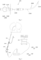
- the puncture system 100 includes the puncture needle assembly 1000 and a dilator 2000.
- the puncture needle assembly 1000 includes a needle holder 1100 and a needle 1200.
- the needle holder 1100 includes a conductor 1110.
- the needle holder 1100 comprises a channel axially extending therethrough. At least a part of a sidewall of the channel is provided by the conductor 1110.
- a proximal end portion of the needle 1200 extends in the channel and is connected to the conductor 1110.
- the dilator 2000 includes a hollow dilation catheter 2100, and a distal end of the needle 1200 extends through the dilation catheter 2100 into human tissue to perform puncture.
- the distal end of the needle 1200 establishes electrical connection with the blood for capturing electrical signal therefrom.
- the proximal end of the needle 1200 is coupled to a three-dimensional locating device 200 such as an electrophysiological locating device.
- the three-dimensional locating device 200 receives the electrical signals and, based thereon, locates the distal end of the needle 1200.
- the conductor 1110 provided in the needle holder 1100 is coupled to the three-dimensional locating device, thereby establishing electrical connection between the needle 1200 and the three-dimensional locating device 200. This dispenses with the need to provide an additional lead on the needle 1100, enhancing manipulability of the puncture needle assembly 1000.
- the conductor 1110 may be fabricated from a metallic conductive material such as stainless steel, aluminum or the like.
- the needle 1200 may be an elongate hollow structure made of a metallic conductive material. It may be either an integral one-piece tube or consisting of two tube sections that are coupled together.
- a distal end portion of the needle 1200 may be bendable, and the needle 1200 may have a diameter that is smaller at the distal end than at the proximal end.
- the distal end portion may be provided with a sharp tip which can facilitate puncture of human tissue.
- the proximal end portion of the needle 1200 is electrically connected to the conductor 1110, enabling transfer of the electrical signals to the conductor 1110 and further to the three-dimensional locating device 200.
- the needle holder 1100 is overall configured as the conductor 1110. In these cases, the entire sidewall of the channel is provided by the conductor 1110. For conventional puncture needles, physicians would want their needle holders to provide desired hand sensation during manipulation. This requires the needle holders to weigh in a certain range. Providing the needle holder overall as the conductor 1110 can satisfy this requirement. However, if the conductor is made of a metal, it will be expensive. Moreover, the commonly used metal copper has poor biocompatibility and must be subject to surface coating. However, as the channel is very narrow, its surface coating would be technically challenging. If biocompatible stainless steel is to be used as the material of the conductor, it would be difficult to machine it to a desired shape due to the poor plasticity.
- the needle holder 1100 further includes an insulator 1120.
- the insulator 1120 and the conductor 1110 may be separately fabricated and then coupled together.
- the conductor 1110 may provide a part of the sidewall of the channel, and the insulator 1120 may provide the rest of the sidewall of the channel. This can not only reduce the metallic material used and hence the cost of the puncture needle assembly 1000, but also allows the insulator 1120 to be made of a polymer material with good biocompatibility, which is safe for the human body and easy to process.
- the structure of the needle holder 1100 may be designed as practically desired.
- the conductor 1110 is usually designed as a block-shaped structure. This design can not only facilitate gripping by the physician, but also enables the needle holder to have a desired weight that gives the physician desired hand sensation.
- the conductor 1110 and the insulator 1120 are axially arranged side by side in an axial direction of the needle holder 1100.
- the conductor 1110 comprises a first through bore that extends axially and the insulator comprises a second through bore that extends axially and communicates with the first through bore to make up the channel.
- the insulator 1120 comprises a first lumen axially extending therethrough and forming a part of the channel, and the insulator 1120 is provided with a window in communication with the first lumen.
- the conductor 1110 is located within the window, and inner surface of the conductor 1110 and inner surface of the first lumen together define the channel.
- the needle 1200 is disposed within the channel so as to be connected to the conductor 1110.
- an inner diameter of the channel is typically greater than an outer diameter of the proximal end portion of the needle 1200. However, this leaves a clearance between the needle 1200 and the conductor 1110, which makes their connection unreliable.
- a conductive adhesive is filled between the inner surface of the conductor 1110 and an outer surface of the needle 1200.
- the conductive adhesive can cure into a conductive adhesive layer (not shown), which can strengthen the connection between the conductor 1110 and the needle 1200, ensuring smooth transmission of the electrical signals captured at the distal end of the needle 1200 to the three-dimensional locating device 200 via the conductor 1110.
- a first biasing element 1130 may be provided to solve the problem of unreliable connection between the conductor 1110 and the needle 1200 that arises from the unmatched inner and outer diameters of the channel and the needle 1200.
- an accommodating recess 1131 may be provided in the inner surface of the conductor 1110 (see Fig. 9 ), and the first biasing element 1130 may be disposed in the accommodating recess 1131 and configured to store biasing energy which causes the first biasing element 1130 to abut against the needle 1200, thereby bringing the needle 1200 into tight contact with the inner surface of the conductor 1110.
- Examples of the first biasing element 1130 may include, but are not limited to, a spring. In case of the first biasing element 1130 being implemented as a spring, an axis of the spring is perpendicular to an axis of the needle 1200.
- the insulator 1120 may also be connected to the needle 1200 to enhance connection reliability of the needle 1200 with the needle holder 1100 and prevent dislodgement of the needle 1200 during use.
- the conductor 1110 in the puncture needle assembly 100 may be coupled to a connecting lead of the three-dimensional locating device 200 through a conductive clip.
- the conductor 1110 is provide therein with a socket 1113 for receiving a contact pin of the connecting lead.
- the conductor 1110 may include a main body 1111 and an extension 1112 joined to the main body 1111.
- the main body 1111 may be connected to the needle 1200, while the socket 1113 may be provided in the extension 1112.
- the main body 1111 may be axially connected to the needle 1200.
- the needle holder 1100 may include the insulator 1120 to reduce the metallic material used and hence the cost of the puncture needle assembly 1000 and enhance biological safety.
- the insulator 1120 may include a first insulator portion 1120a and a second insulator portion 1120b.
- the extension 1112 may be fitted over at least a part of the first insulator portion 1120a, and the main body 1111 may be provided between the first insulator portion 1120a and the second insulator portion 1120b.
- This design not only enables desired connection with the three-dimensional locating device 200 but also takes into account biological safety and cost. In the example with the contact pin mating with the socket 1113, all inner sidewalls of the socket 1113 may be conductive. This can additionally enhance the stability and reliability of signal transmission.
- the insulator may be partially fitted over the conductor, and the socket may be provided in the insulator.
- the socket may extend to the conductor so that the contact pin, when inserted into the socket, can come into electrical connection with the conductor.
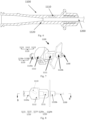
- the dilation catheter 2100 of the dilator 2000 is an elongate structure and has a tip at distal end portion thereof.
- the dilation catheter 2100 comprises a second lumen extending axially therethrough, and an inner surface of the dilation catheter 2100 comprises a step 2110 for limiting a length of the needle 1200 that protrudes out of the distal end of the dilation catheter 2100 because an excessive protruded length of the needle 1200 may be hazardous.
- the dilation catheter 2100 comprises, around the distal end thereof, a side hole 2120 in communication with the second lumen of the dilation catheter 2100.
- the side hole 2120 can establish electrical connection of the needle 1200 with the blood outside of the dilation catheter 2100.
- the distal end of the needle 1200 can be hidden within the dilation catheter 2100 of the dilator 2000 while capturing electrical signals by virtue of its electrical connection with the blood established by the side hole 2120, thus avoiding causing injury to human tissue during the search for the target puncture site.
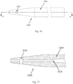
- the side hole 2120 may have any suitable cross-sectional shape, such as circular (see Figs. 14 and 15 ), square (see Figs. 16 and 17 ), oblong, polygonal, irregular, etc. Further, either one or more such side holes 2120 may be provided. For example, two side holes 2120 may be provided in symmetry at the distal end of the dilation catheter 2100.
- the dilator 2000 further includes a conductive biasing member 2200, which is disposed within the side hole 2120. When the conductive biasing member 2200 comes into contact with the blood, electrical connection between the blood and the needle 1200 is established.
- the conductive biasing member 2200 includes a second biasing element 2210, which is a curved metal sheet comprising an arc-shaped portion 2211.
- a second biasing element 2210 which is a curved metal sheet comprising an arc-shaped portion 2211.
- One end of the arc-shaped portion 2211 is secured at the side hole 2120, and the other end thereof is free. At least a part of the arc-shaped portion 2211 bulges beyond the inner surface of the dilation catheter 2100.
- the arc-shaped portion 2211 abuts against the needle 1200 around the distal end thereof to bring the needle 1200 into effective contact with the conductive biasing member 2200.
- the conductive biasing member 2200 may further include an end cap 2220 and a frame 2230.
- the end cap 2220 may be integrally formed with the frame 2230, or they may be separate components which are joined together suitably, for example, by welding.
- the end cap 2220 may be secured to an inner sidewall of the side hole 2120, and the non-free end of the arc-shaped portion 2211 may be secured to an inner sidewall of the frame 2230.
- the conductive biasing member 2200 may further include a stopper 2240 disposed on the arc-shaped portion 2211.
- the stopper 2240 is joined to the free end of the arc-shaped portion 2211.
- the second biasing element 2210 When the needle 1200 comes into contact with the arc-shaped portion 2211, the second biasing element 2210 will be deflected to cause the stopper 2240 to move toward the end cap 2220 and finally come into contact with the end cap 2220.
- the conductive biasing member 2200 can not only enhance the electrical connection between the needle 1200 and the blood but can also give the physician improved hand sensation.
- the needle 1200 upon the distal end of the needle 1200 coming into contact with the arc-shaped portion 2211, the needle 1200 will be subject to resistance from the arc-shaped portion 2211, providing the physician with tactile feedback that informs the physician in a timely manner of the arrival of the distal end of the needle 1200 at the side hole.
- an annular groove may be formed in the inner sidewall of the side hole 2120, and the end cap 2220 may comprise a protrusion 2221 that is complementary in shape to the annular groove.
- the protrusion 2221 may engage with the annular groove, thereby firmly securing the end cap 2220 in the side hole 2120.
- the transseptal puncture process includes the following steps: Step S1: Advance a guidewire in the right femoral vein to the junction of the superior vena cava and the subclavian vein.
- Step S2 Assemble the dilator 2000 with a catheter sheath 300, and advance them together over the guidewire into the superior vena cava.
- Step S3 Withdraw the guidewire and flush the catheter sheath 300 with a heparin-saline solution.
- Step S4 Couple the conductor 1110 of the puncture needle assembly 1000 to the three-dimensional locating device 200 and insert the needle 1200 into the dilation catheter 2100 of the dilator 2000 until the distal end of the needle 1200 reaches the side hole 2120 and comes into contact with the conductive biasing member 2200, thereby enabling the three-dimensional locating device 200 to locate the distal end of the needle 1200.
- Step S5 Retract the catheter sheath 300, the dilator 2000 and the needle 1200, rotate the needle 1200, and determine the fossa ovalis based on the locations of the His bundle and coronary sinus in an image displayed on the three-dimensional locating device 200, and stop retracting the catheter sheath 300, the dilator 2000 and the needle 1200 upon determination of the fossa ovalis.
- Step S6 Identify the target puncture site which is at a location of the septum 1/3 posterior to the His bundle level.
- Step S7 Advance the dilator 2000 and the catheter sheath 300 a distance of about 2-3 mm.
- Step S8 With the catheter sheath 300 and the dilator 2000 being held stationary, advance the needle 1200 about 5-10 mm according to an image displayed on the three-dimensional locating device 200 so that the distal end of the needle 1200 extends out of the distal end of the dilation catheter 2100 and penetrates the atrial septum.
- Step S9 With the needle 1200 being held stationary, advance the catheter sheath 300 and the dilator 2000 so that a distal end of the dilator 2000 enters the left atrium.
- Step S 10 Withdraw the needle 1200 out of the patient's body, with the dilator 2000 still being held stationary.
- Step S11 Advance the catheter sheath 300 so that its distal end also enters the left atrium.
- Step S12 With the catheter sheath 300 being held stationary, withdraw the dilator 2000 out of the patient's body, thus ending the puncture process.
- Embodiments of the present invention provide a puncture needle assembly and a puncture system.
- the puncture needle assembly includes a needle holder and a needle.
- the needle holder includes a conductor, and a proximal end portion of the needle is disposed in the needle holder and connected to the conductor.
- the conductor establishes signal communication between the needle and a three-dimensional locating device, which can increase safety and a success rate of transseptal puncture.
- the puncture system includes the puncture needle assembly and a dilator.
- the dilator includes a dilation catheter comprising a lumen axially extending therethrough.
- the dilation catheter is distally provided therein with a side hole in communication with the lumen, and a conductive biasing member is disposed in the side hole.
- a conductive biasing member is disposed in the side hole.
Landscapes
- Health & Medical Sciences (AREA)
- Life Sciences & Earth Sciences (AREA)
- Surgery (AREA)
- Engineering & Computer Science (AREA)
- Animal Behavior & Ethology (AREA)
- Public Health (AREA)
- Biomedical Technology (AREA)
- Veterinary Medicine (AREA)
- Heart & Thoracic Surgery (AREA)
- General Health & Medical Sciences (AREA)
- Medical Informatics (AREA)
- Molecular Biology (AREA)
- Nuclear Medicine, Radiotherapy & Molecular Imaging (AREA)
- Pathology (AREA)
- Physics & Mathematics (AREA)
- Plasma & Fusion (AREA)
- Otolaryngology (AREA)
- Gastroenterology & Hepatology (AREA)
- Hematology (AREA)
- Cardiology (AREA)
- Robotics (AREA)
- Anesthesiology (AREA)
- Vascular Medicine (AREA)
- Surgical Instruments (AREA)
- Measurement And Recording Of Electrical Phenomena And Electrical Characteristics Of The Living Body (AREA)
- Infusion, Injection, And Reservoir Apparatuses (AREA)
Applications Claiming Priority (2)
| Application Number | Priority Date | Filing Date | Title |
|---|---|---|---|
| CN202010399181.5A CN111557713B (zh) | 2020-05-12 | 2020-05-12 | 一种穿刺针组件及穿刺系统 |
| PCT/CN2021/092514 WO2021228003A1 (zh) | 2020-05-12 | 2021-05-08 | 一种穿刺针组件及穿刺系统 |
Publications (2)
| Publication Number | Publication Date |
|---|---|
| EP4137074A1 true EP4137074A1 (de) | 2023-02-22 |
| EP4137074A4 EP4137074A4 (de) | 2023-12-06 |
Family
ID=72068147
Family Applications (1)
| Application Number | Title | Priority Date | Filing Date |
|---|---|---|---|
| EP21803771.1A Withdrawn EP4137074A4 (de) | 2020-05-12 | 2021-05-08 | Punktionsnadelanordnung und punktionssystem |
Country Status (4)
| Country | Link |
|---|---|
| US (1) | US20230190332A1 (de) |
| EP (1) | EP4137074A4 (de) |
| CN (1) | CN111557713B (de) |
| WO (1) | WO2021228003A1 (de) |
Families Citing this family (3)
| Publication number | Priority date | Publication date | Assignee | Title |
|---|---|---|---|---|
| CN111557713B (zh) * | 2020-05-12 | 2025-03-07 | 上海微创电生理医疗科技股份有限公司 | 一种穿刺针组件及穿刺系统 |
| CN114869430B (zh) * | 2022-06-08 | 2025-09-19 | 环心医疗科技(苏州)有限公司 | 房间隔穿刺系统 |
| CN115919431B (zh) * | 2023-03-09 | 2023-06-09 | 上海微创电生理医疗科技股份有限公司 | 房间隔穿刺装置 |
Family Cites Families (16)
| Publication number | Priority date | Publication date | Assignee | Title |
|---|---|---|---|---|
| NO20010184A (no) * | 2001-01-11 | 2002-04-22 | Medinnova As | Anordning for lokalisering av fossa ovalis |
| US10493259B2 (en) * | 2003-01-21 | 2019-12-03 | Baylis Medical Company Inc. | Medical apparatus for fluid communication |
| US8398656B2 (en) * | 2003-01-30 | 2013-03-19 | Integrated Vascular Systems, Inc. | Clip applier and methods of use |
| EP2136706A1 (de) * | 2007-04-18 | 2009-12-30 | Medtronic, Inc. | Permanent implantierbare medizinische elektroleitungen mit aktivbefestigung und entsprechende verfahren zur nichtfluoroskopischen implantation |
| US20130296729A1 (en) * | 2012-05-04 | 2013-11-07 | Biosense Webster (Israel), Ltd. | Catheter having two-piece connector for a split handle assembly |
| CN105342671B (zh) * | 2014-08-20 | 2018-01-05 | 祝金明 | 穿刺针组件 |
| CN106618685B (zh) * | 2015-10-30 | 2019-10-11 | 四川锦江电子科技有限公司 | 一种用于房间隔穿刺的鞘管 |
| CN107693089A (zh) * | 2016-08-09 | 2018-02-16 | 上海交通大学医学院附属新华医院 | 三维房间隔穿刺系统 |
| AU2018247588B2 (en) * | 2017-04-04 | 2023-03-16 | Neuraura Biotech Inc. | Apparatus and method for capturing neural recordings |
| CN107280714A (zh) * | 2017-06-27 | 2017-10-24 | 李毅刚 | 血管介入诊疗系统 |
| CN110709023A (zh) * | 2017-06-30 | 2020-01-17 | 直观外科手术操作公司 | 具有柔顺性弹性体电极的电外科手术器械 |
| CN209091556U (zh) * | 2018-05-30 | 2019-07-12 | 蔡衡 | 三维房间隔穿刺组件 |
| CN110547857B (zh) * | 2018-05-30 | 2025-02-18 | 蔡衡 | 三维房间隔穿刺组件 |
| CN210158675U (zh) * | 2019-01-04 | 2020-03-20 | 科塞尔医疗科技(苏州)有限公司 | 一种房间隔穿刺针组件 |
| CN111557713B (zh) * | 2020-05-12 | 2025-03-07 | 上海微创电生理医疗科技股份有限公司 | 一种穿刺针组件及穿刺系统 |
| CN212415859U (zh) * | 2020-05-12 | 2021-01-29 | 上海微创电生理医疗科技股份有限公司 | 一种穿刺针组件及穿刺系统 |
-
2020
- 2020-05-12 CN CN202010399181.5A patent/CN111557713B/zh active Active
-
2021
- 2021-05-08 EP EP21803771.1A patent/EP4137074A4/de not_active Withdrawn
- 2021-05-08 US US17/925,197 patent/US20230190332A1/en active Pending
- 2021-05-08 WO PCT/CN2021/092514 patent/WO2021228003A1/zh not_active Ceased
Also Published As
| Publication number | Publication date |
|---|---|
| US20230190332A1 (en) | 2023-06-22 |
| CN111557713A (zh) | 2020-08-21 |
| CN111557713B (zh) | 2025-03-07 |
| WO2021228003A1 (zh) | 2021-11-18 |
| EP4137074A4 (de) | 2023-12-06 |
Similar Documents
| Publication | Publication Date | Title |
|---|---|---|
| EP3997497B1 (de) | Verbindungssysteme und verfahren zur herstellung optischer und elektrischer verbindungen durch ein abdecktuch | |
| CA2134909C (en) | Guiding introducer for left atrium | |
| EP0650741B1 (de) | Einführungsvorrichtung für den rechten Vorhof | |
| US9615759B2 (en) | Devices and methods for ECG guided vascular access | |
| US5833673A (en) | Guiding introducer system for use in the treatment of left ventricular tachycardia | |
| EP4137074A1 (de) | Punktionsnadelanordnung und punktionssystem | |
| EP0727237A1 (de) | Einführungsvorrichtung zur Anwendung bei der Behandlung linksventrikularer Tachykardien | |
| JP7197559B2 (ja) | ガイドワイヤおよび医療デバイス | |
| JP7765669B2 (ja) | 医療用ガイドワイヤアセンブリ及び/又は電気コネクタ | |
| CN104755038A (zh) | 具有用于分离式柄部组件的二件式连接器的导管 | |
| US20160271365A1 (en) | A device for ecg derivation from a catheter | |
| JP2002126096A (ja) | 電極を備えたカテーテル装置 | |
| JP2005137908A (ja) | カテーテル | |
| CN212415859U (zh) | 一种穿刺针组件及穿刺系统 | |
| CN117322975A (zh) | 房间隔穿刺系统 | |
| US20250041021A1 (en) | Positional markers for catheter wires | |
| CN119344835B (zh) | 一种心包穿刺导丝套件 | |
| US20240407773A1 (en) | Stiffer core material for rf perforation device | |
| US20240277399A1 (en) | Rf wire connection in dilator | |
| US20240407705A1 (en) | Shaped dilator for transseptal puncture and electroanatomical mapping | |
| CN110368071A (zh) | 三维房间隔穿刺用扩张器 |
Legal Events
| Date | Code | Title | Description |
|---|---|---|---|
| STAA | Information on the status of an ep patent application or granted ep patent |
Free format text: STATUS: THE INTERNATIONAL PUBLICATION HAS BEEN MADE |
|
| PUAI | Public reference made under article 153(3) epc to a published international application that has entered the european phase |
Free format text: ORIGINAL CODE: 0009012 |
|
| STAA | Information on the status of an ep patent application or granted ep patent |
Free format text: STATUS: REQUEST FOR EXAMINATION WAS MADE |
|
| 17P | Request for examination filed |
Effective date: 20221118 |
|
| AK | Designated contracting states |
Kind code of ref document: A1 Designated state(s): AL AT BE BG CH CY CZ DE DK EE ES FI FR GB GR HR HU IE IS IT LI LT LU LV MC MK MT NL NO PL PT RO RS SE SI SK SM TR |
|
| DAV | Request for validation of the european patent (deleted) | ||
| DAX | Request for extension of the european patent (deleted) | ||
| A4 | Supplementary search report drawn up and despatched |
Effective date: 20231108 |
|
| RIC1 | Information provided on ipc code assigned before grant |
Ipc: A61B 17/00 20060101ALN20231102BHEP Ipc: A61B 34/20 20160101ALI20231102BHEP Ipc: A61B 17/34 20060101AFI20231102BHEP |
|
| STAA | Information on the status of an ep patent application or granted ep patent |
Free format text: STATUS: THE APPLICATION HAS BEEN WITHDRAWN |
|
| 18W | Application withdrawn |
Effective date: 20240930 |