EP4137080A1 - Cathéter doté d'électrodes à taille réglable - Google Patents
Cathéter doté d'électrodes à taille réglable Download PDFInfo
- Publication number
- EP4137080A1 EP4137080A1 EP22190351.1A EP22190351A EP4137080A1 EP 4137080 A1 EP4137080 A1 EP 4137080A1 EP 22190351 A EP22190351 A EP 22190351A EP 4137080 A1 EP4137080 A1 EP 4137080A1
- Authority
- EP
- European Patent Office
- Prior art keywords
- distal
- tube
- electrode
- tissue
- end assembly
- Prior art date
- Legal status (The legal status is an assumption and is not a legal conclusion. Google has not performed a legal analysis and makes no representation as to the accuracy of the status listed.)
- Granted
Links
Images

Classifications
-
- A—HUMAN NECESSITIES
- A61—MEDICAL OR VETERINARY SCIENCE; HYGIENE
- A61B—DIAGNOSIS; SURGERY; IDENTIFICATION
- A61B18/00—Surgical instruments, devices or methods for transferring non-mechanical forms of energy to or from the body
- A61B18/04—Surgical instruments, devices or methods for transferring non-mechanical forms of energy to or from the body by heating
- A61B18/12—Surgical instruments, devices or methods for transferring non-mechanical forms of energy to or from the body by heating by passing a current through the tissue to be heated, e.g. high-frequency current
- A61B18/14—Probes or electrodes therefor
- A61B18/1492—Probes or electrodes therefor having a flexible, catheter-like structure, e.g. for heart ablation
-
- A—HUMAN NECESSITIES
- A61—MEDICAL OR VETERINARY SCIENCE; HYGIENE
- A61B—DIAGNOSIS; SURGERY; IDENTIFICATION
- A61B5/00—Measuring for diagnostic purposes; Identification of persons
- A61B5/24—Detecting, measuring or recording bioelectric or biomagnetic signals of the body or parts thereof
- A61B5/25—Bioelectric electrodes therefor
- A61B5/271—Arrangements of electrodes with cords, cables or leads, e.g. single leads or patient cord assemblies
-
- A—HUMAN NECESSITIES
- A61—MEDICAL OR VETERINARY SCIENCE; HYGIENE
- A61B—DIAGNOSIS; SURGERY; IDENTIFICATION
- A61B5/00—Measuring for diagnostic purposes; Identification of persons
- A61B5/24—Detecting, measuring or recording bioelectric or biomagnetic signals of the body or parts thereof
- A61B5/316—Modalities, i.e. specific diagnostic methods
- A61B5/318—Heart-related electrical modalities, e.g. electrocardiography [ECG]
- A61B5/346—Analysis of electrocardiograms
- A61B5/349—Detecting specific parameters of the electrocardiograph cycle
- A61B5/361—Detecting fibrillation
-
- A—HUMAN NECESSITIES
- A61—MEDICAL OR VETERINARY SCIENCE; HYGIENE
- A61B—DIAGNOSIS; SURGERY; IDENTIFICATION
- A61B5/00—Measuring for diagnostic purposes; Identification of persons
- A61B5/24—Detecting, measuring or recording bioelectric or biomagnetic signals of the body or parts thereof
- A61B5/316—Modalities, i.e. specific diagnostic methods
- A61B5/318—Heart-related electrical modalities, e.g. electrocardiography [ECG]
- A61B5/346—Analysis of electrocardiograms
- A61B5/349—Detecting specific parameters of the electrocardiograph cycle
- A61B5/363—Detecting tachycardia or bradycardia
-
- A—HUMAN NECESSITIES
- A61—MEDICAL OR VETERINARY SCIENCE; HYGIENE
- A61B—DIAGNOSIS; SURGERY; IDENTIFICATION
- A61B5/00—Measuring for diagnostic purposes; Identification of persons
- A61B5/24—Detecting, measuring or recording bioelectric or biomagnetic signals of the body or parts thereof
- A61B5/316—Modalities, i.e. specific diagnostic methods
- A61B5/318—Heart-related electrical modalities, e.g. electrocardiography [ECG]
- A61B5/367—Electrophysiological study [EPS], e.g. electrical activation mapping or electro-anatomical mapping
-
- A—HUMAN NECESSITIES
- A61—MEDICAL OR VETERINARY SCIENCE; HYGIENE
- A61B—DIAGNOSIS; SURGERY; IDENTIFICATION
- A61B5/00—Measuring for diagnostic purposes; Identification of persons
- A61B5/48—Other medical applications
- A61B5/4848—Monitoring or testing the effects of treatment, e.g. of medication
-
- A—HUMAN NECESSITIES
- A61—MEDICAL OR VETERINARY SCIENCE; HYGIENE
- A61B—DIAGNOSIS; SURGERY; IDENTIFICATION
- A61B5/00—Measuring for diagnostic purposes; Identification of persons
- A61B5/68—Arrangements of detecting, measuring or recording means, e.g. sensors, in relation to patient
- A61B5/6846—Arrangements of detecting, measuring or recording means, e.g. sensors, in relation to patient specially adapted to be brought in contact with an internal body part, i.e. invasive
- A61B5/6847—Arrangements of detecting, measuring or recording means, e.g. sensors, in relation to patient specially adapted to be brought in contact with an internal body part, i.e. invasive mounted on an invasive device
- A61B5/6852—Catheters
- A61B5/6858—Catheters with a distal basket, e.g. expandable basket
-
- A—HUMAN NECESSITIES
- A61—MEDICAL OR VETERINARY SCIENCE; HYGIENE
- A61B—DIAGNOSIS; SURGERY; IDENTIFICATION
- A61B5/00—Measuring for diagnostic purposes; Identification of persons
- A61B5/68—Arrangements of detecting, measuring or recording means, e.g. sensors, in relation to patient
- A61B5/6846—Arrangements of detecting, measuring or recording means, e.g. sensors, in relation to patient specially adapted to be brought in contact with an internal body part, i.e. invasive
- A61B5/6847—Arrangements of detecting, measuring or recording means, e.g. sensors, in relation to patient specially adapted to be brought in contact with an internal body part, i.e. invasive mounted on an invasive device
- A61B5/6852—Catheters
- A61B5/6859—Catheters with multiple distal splines
-
- A—HUMAN NECESSITIES
- A61—MEDICAL OR VETERINARY SCIENCE; HYGIENE
- A61B—DIAGNOSIS; SURGERY; IDENTIFICATION
- A61B18/00—Surgical instruments, devices or methods for transferring non-mechanical forms of energy to or from the body
- A61B2018/00053—Mechanical features of the instrument of device
- A61B2018/00059—Material properties
- A61B2018/00071—Electrical conductivity
- A61B2018/00077—Electrical conductivity high, i.e. electrically conducting
-
- A—HUMAN NECESSITIES
- A61—MEDICAL OR VETERINARY SCIENCE; HYGIENE
- A61B—DIAGNOSIS; SURGERY; IDENTIFICATION
- A61B18/00—Surgical instruments, devices or methods for transferring non-mechanical forms of energy to or from the body
- A61B2018/00053—Mechanical features of the instrument of device
- A61B2018/00214—Expandable means emitting energy, e.g. by elements carried thereon
- A61B2018/00267—Expandable means emitting energy, e.g. by elements carried thereon having a basket shaped structure
-
- A—HUMAN NECESSITIES
- A61—MEDICAL OR VETERINARY SCIENCE; HYGIENE
- A61B—DIAGNOSIS; SURGERY; IDENTIFICATION
- A61B18/00—Surgical instruments, devices or methods for transferring non-mechanical forms of energy to or from the body
- A61B2018/00315—Surgical instruments, devices or methods for transferring non-mechanical forms of energy to or from the body for treatment of particular body parts
- A61B2018/00345—Vascular system
- A61B2018/00351—Heart
-
- A—HUMAN NECESSITIES
- A61—MEDICAL OR VETERINARY SCIENCE; HYGIENE
- A61B—DIAGNOSIS; SURGERY; IDENTIFICATION
- A61B18/00—Surgical instruments, devices or methods for transferring non-mechanical forms of energy to or from the body
- A61B2018/00571—Surgical instruments, devices or methods for transferring non-mechanical forms of energy to or from the body for achieving a particular surgical effect
- A61B2018/00577—Ablation
-
- A—HUMAN NECESSITIES
- A61—MEDICAL OR VETERINARY SCIENCE; HYGIENE
- A61B—DIAGNOSIS; SURGERY; IDENTIFICATION
- A61B18/00—Surgical instruments, devices or methods for transferring non-mechanical forms of energy to or from the body
- A61B2018/00636—Sensing and controlling the application of energy
- A61B2018/00773—Sensed parameters
- A61B2018/00839—Bioelectrical parameters, e.g. ECG, EEG
-
- A—HUMAN NECESSITIES
- A61—MEDICAL OR VETERINARY SCIENCE; HYGIENE
- A61B—DIAGNOSIS; SURGERY; IDENTIFICATION
- A61B2505/00—Evaluating, monitoring or diagnosing in the context of a particular type of medical care
- A61B2505/05—Surgical care
Definitions
- the present invention relates generally to medical catheters, and particularly to a catheter having electrodes with an adjustable size.
- European Patent Application EP3141181A1 describes an ablation catheter having an elongated body member, a basket including a plurality of radially expanding splines and a first electrode located on one of the radially expanding splines.
- the first electrode configured to apply energy to tissue adjacent to the radially expanding splines during an ablation procedure.
- At least one of the radially expanding splines includes at least one aperture, a lumen, an optical emitting element inside the lumen and an optical receiving element inside the lumen.
- the optical emitting element is configured to emit optical radiation through the aperture and into adjacent tissue during the ablation procedure while the optical receiving element is configured to collect optical radiation through the aperture during the ablation procedure.
- the optical radiation indicates characteristics of adjacent tissue during the ablation procedure.
- U.S. Patent Application Publication No. 2020/0206461 describes a system that includes an expandable distal-end assembly, a proximal position sensor, a distal position sensor, and a processor.
- the expandable distal-end assembly is coupled to a distal end of a shaft for insertion into a cavity of an organ of a patient.
- the proximal and distal position sensors are located at a proximal end and a distal end of the distal-end assembly, respectively.
- the processor is configured to estimate a position and a longitudinal direction of the proximal sensor, and a position of the distal sensor, all in a coordinate system used by the processor.
- An embodiment of the present invention that is described herein provides a method including, inserting into an organ of a patient, a catheter having an expandable distal-end assembly, which is coupled to a shaft and includes multiple splines, at least a given spline among the multiple splines includes an electrode that is being placed in contact with tissue of the organ. At least a size of a section of the electrode in contact with the tissue, is controlled by moving a tube over at least a portion of the expandable distal-end assembly.
- controlling at least the size includes, controlling a position of at least the given spline along a perimeter of the tube.
- the splines are coupled between a distal apex and a proximal apex of the distal-end assembly, and controlling at least the size includes: (i) moving the tube toward the proximal apex for increasing the size of the section, and (ii) moving the tube toward the distal apex for reducing the size of the section.
- moving the tube includes using a stopper of the tube for limiting the movement of the tube between the proximal apex and the distal apex of the distal-end assembly.
- At least the given spline is electrically conductive and the electrode is used for one or both of: (i) applying an ablation signal to the tissue, and (ii) sensing an electro-anatomic (EA) signal in the tissue.
- the method includes: (i) applying the ablation signal when the size of the section is increased, and (ii) sensing the EA signal when the size of the section is reduced.
- a catheter that includes: (i) a shaft for insertion into an organ of a patient, (ii) an expandable distal-end assembly, which is coupled to the shaft and includes multiple splines, at least a given spline among the multiple splines includes an electrode that is configured to be placed in contact with tissue of the organ, and (iii) a tube, which is configured to be threaded over at least a portion of the expandable distal-end assembly, and is movable along the distal-end assembly for controlling at least a size of a section of the electrode in contact with the tissue, the tube has a stopper for limiting a movement of the tube relative to the distal-end assembly.
- the tube has at least a channel for controlling a position of at least the given spline along a perimeter of the tube.
- the splines are coupled between a distal apex and a proximal apex of the distal-end assembly, and the tube is configured to be moved: (i) toward the proximal apex for increasing the size of the section, and (ii) toward the distal apex for reducing the size of the section.
- a method for producing a catheter includes coupling, to a shaft, an expandable distal-end assembly, which includes multiple splines, and at least a given spline among the multiple splines includes an electrode that is configured to be placed in contact with tissue of an organ of a patient.
- the tube has at least a channel for controlling a position of at least one of the splines along a perimeter of the tube.
- the splines are coupled between a distal apex and a proximal apex of the distal-end assembly, and the stopper is configured to limit the movement of the tube between the distal apex and the proximal apex for controlling at least the size of the section.
- a catheter having one or more sensing electrodes for the EA sensing, and one or more ablation electrodes for the tissue ablation.
- different catheters one for sensing and another for ablation.
- the first option requires a complex catheter, which may cause operational challenges (e.g., by coupling different type of electrode(s) to the tissue during the EA mapping and tissue ablation).
- the second option requires insertion of two different catheters to the patient heart. In summary, both options are increasing the cycle time and the cost of the electrophysiological procedure.
- a catheter configured for performing both EA mapping and tissue ablation comprises: (i) a shaft for insertion into an organ (e.g. a heart) of a patient, (ii) an expandable distal-end assembly, which is coupled to the shaft and comprises multiple splines, and (iii) a movable tube.
- the tube has a stopper for limiting the movement of the tube relative to the distal-end assembly, for example, between a proximal apex and a distal apex of the distal-end assembly.
- one or more additional electrodes are coupled to the tube and are electrically wired to the catheter, but are not intended to be electrically connected with any of the splines, or to be placed in contact with the tissue in question.
- the catheter is configured to sense and/or to apply: (i) a unipolar signal between a selected electrode of the catheter (e.g., a section of a spline) in contact with the tissue and the additional electrode, and/or (ii) a bipolar signal between two selected electrodes (e.g., sections of two different spline) of the distal-end assembly.
- the physician may obtain high-resolution EA mapping (by using smaller electrodes). Subsequently, based on the EA mapping, the physician may increase the size of the electrode, e.g., by moving the tube distally along the longitudinal axis, for ablating the given area described above, or for ablating any other area of the tissue having a size typically larger than the area of the tissue that is covered, e.g., by the electrode, for the EA mapping.
- the disclosed techniques improve the quality of electrophysiological procedures by adjusting the size of the electrode to correspond with the size required for the EA mapping and/or tissue ablation. Moreover, the disclosed techniques reduce the cycle time of electrophysiological procedures, by allowing a quick and simply adjustment of the electrode-size, and thereby, a quick switch between EA mapping of tissue and ablation of the tissue.
- the disclosed techniques reduce the cost of electrophysiological procedures, by enabling the physician to carry out both sensing EA signals in tissue and ablating the tissue using a simple catheter that typically costs less than two different catheters, or a complex catheter having to or more different types of electrodes.
- Fig. 1 is a schematic, pictorial illustration of a catheter-based position-tracking and ablation system 20, in accordance with an exemplary embodiment of the present invention.
- system 20 comprises a catheter 22, in the present example an expandable cardiac catheter having a basket shape, and a control console 24.
- catheter 22 may be used for any suitable therapeutic and/or diagnostic purposes, such as but not limited to ablation of tissue in a heart 26.
- console 24 comprises a processor 42, typically a general-purpose computer, with suitable front end and interface circuits for receiving signals from catheter 22 and for controlling other components of system 20 described herein.
- Processor 42 may be programmed in software to carry out the functions that are used by the system, and is configured to store data for the software in a memory 51.
- the software may be downloaded to console 24 in electronic form, over a network, for example, or it may be provided on non-transitory tangible media, such as optical, magnetic or electronic memory media.
- some or all of the functions of processor 42 may be carried out using an application-specific integrated circuit (ASIC) or any suitable type of programmable digital hardware components.
- ASIC application-specific integrated circuit
- catheter 22 comprises a position sensor 39 of a position tracking system, which is coupled to the distal end of catheter 22, e.g., in close proximity to distal-end assembly 40.
- position sensor 39 comprises a magnetic position sensor, but in other embodiments, any other suitable type of position sensor (e.g., other than magnetic based) may be used.
- processor 42 receives signals from magnetic position sensor 39 in response to magnetic fields from external field generators 36, for example, for the purpose of measuring the position of distal-end assembly 40 in heart 26.
- console 24 comprises a driver circuit 34, configured to drive magnetic field generators 36.
- Magnetic field generators 36 are placed at known positions external to patient 28, e.g., below table 29.
- processor 42 is configured to display, e.g., on a display 46 of console 24, the tracked position of distal-end assembly 40 overlaid on an image 44 of heart 26.
- the method of position sensing using external magnetic fields is implemented in various medical applications, for example, in the CARTO TM system, produced by Biosense Webster Inc. (Irvine, Calif.) and is described in detail in U.S. Patent Nos. 5,391,199 , 6,690,963 , 6,484,118 , 6,239,724 , 6,618,612 and 6,332,089 , in PCT Patent Publication WO 96/05768 , and in U.S. Patent Application Publication Nos. 2002/0065455 A1 , 2003/0120150 A1 and 2004/0068178 A1 , whose disclosures are all incorporated herein by reference.
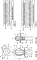
- distal-end assembly 40 is coupled to shaft 23 and is navigated by physician 30 to be placed in contact with tissue in question of heart 26 or with tissue of any other organ of the patient, as described in Fig. 1 above.
- distal-end assembly 40 is expandable, in the present example having a basket shape, but in other embodiments, distal-end assembly 40 may have any other suitable type of an expandable shape.
- distal-end assembly 40 has splines 33 coupled between a proximal apex 66 and a distal apex 77 thereof.
- splines 33 are made from nitinol or any other suitable biocompatible material.
- Splines 33 are electrically conductive and can be electrically shorted or isolated from one another, e.g., by apexes 66 and 77 or using any other suitable electrically insulating apparatus.
- one or more of splines 33 may have electrically isolated surfaces at both edges and an electrically conductive surface between the edges that may serve as an electrode.
- at least one of apexes 66 and 77 may be electrically conductive.
- apexes 66 and 77 are movable relative to one another so as to expand and collapse distal-end assembly 40.
- apex 66 is moved distally in a direction indicated by arrow 72, which is parallel to an axis 68 of catheter 22, so as to expand distal-end assembly 40.
- apex 66 is moved proximally along axis 68, so as to collapse distal-end assembly 40.
- axis 68 constitutes a longitudinal axis of both catheter 22 and distal-end assembly 40.
- distal-end assembly 40 may have two position sensors 39 coupled to, in adjacent to, apexes 66 and 77, respectively. Based on the position signals received from position sensors 39, processor 42 calculates the distance between apexes 66 and 77, and thereby, the expansion-level of distal-end assembly 40.
- tube 55 has a diameter 88, which may be fixed or altered along axis 68, and at least one electrode 70 coupled to the surface of the inner or outer perimeter of tube 55.
- Electrode 70 is configured to be used, for example, as a reference electrode for applying, to the tissue in question, a unipolar ablation signal between the electrode of a given spline 33 and electrode 70.
- electrode 70 may be used as a reference electrode for sensing, in the tissue in question, a unipolar EA signal between the electrode of given spline 33 and electrode 70. Note that in such embodiments, electrode 70 is not intended to be placed in contact with the tissue in question and the electrode of given spline 33 is placed in contact with the tissue in question.
- tube 55 is configured to be threaded over at least a portion of shaft 23, and over at least a portion of distal-end assembly 40.
- Tube 55 is configured to be moved proximally and distally along axis 68, for controlling at least the size of a section described herein of the electrode, which is made from one or more splines 33, and is placed in contact with the tissue.
- tube 55 has a stopper 99 formed on an upper edge 75 of tube 55. Stopper 99, whose structure is described herein, is configured for limiting the movement of tube 55 relative to distal-end assembly 40.
- edge 75 of tube 55 is placed in contact with apex 66, so that stopper 99 is configured to limit tube 55 to move only distally in direction 72 parallel to axis 68.
- upper edge 75 of tube 55 has an inner perimeter 82 and an outer perimeter 86 defining a donut-shape.
- a surface 84 between perimeters 82 and 86 comprises a solid surface, which is configured to limit the movement of upper edge 75 of tube 55 between apexes 66 and 77 as will be described in detail below.
- stopper 99 is consisting of surface 84 and perimeters 82 and 86.
- the minimal diameter of stopper 99 e.g., the circle surrounded by inner perimeter 82, is larger than the diameter of shaft 23, so that tube 55 can be moved, over shaft 23 and at least a portion of distal-end assembly 40, along axis 68.
- stopper 99 when tube 55 is moved distally in direction 72, stopper 99 is configured to limit the movement of tube 55 such that upper edge 75 cannot be positioned distally to apex 77.
- surface 84 collides into the upper edge section of splines 33 that are coupled to distal apex 77, and therefore, limits the distal movement of upper edge 75 of tube 55, beyond distal apex 77.
- distal-end assembly 40 in the position shown in Fig. 2A , (i) distal-end assembly 40 is expanded, and (ii) tube 75 is positioned at its proximal-most position relative to distal-end assembly 40, such that edge 75 is placed in contact with apex 66.
- distal-end assembly 40 has a maximal length of a section 60 (whose size is provided below), and a maximal diameter 90 (e.g., about 12 mm). Therefore, the entire outer surface of splines 33 is exposed to heart 26, and one or more of splines 33 may be placed in contact with the tissue of heart 26.
- a maximal size of a section of the electrodes (e.g., splines 33) of distal-end assembly 40 may be placed in contact with the tissue.
- physician 30 may use system 20 for applying one or more ablation signals (e.g., ablation pulses) to one or more respective splines 33 that are placed in contact with the tissue, so as to form a lesion at one or more intended positions in the tissue.
- ablation signals e.g., ablation pulses
- physician 30 may use system 20 for sensing one or more EA signals in the tissue, but the position shown in Fig. 2A is typically used for ablation, whereas smaller electrodes are typically used for sensing the EA signals.
- physician 30 or any other used of system 20 may adjust or control the size of the electrode (e.g., a section of spline 33) placed in contact with the tissue of heart 26.
- stopper 99 is configured to limit the movement of upper edge 75 of tube 55, between proximal apex 66 and distal apex 77 of the distal-end assembly 40.
- tube 55 has stopper 99 for limiting the movement of tube 55 between proximal axes 66 and distal apex 77 of distal-end assembly 40.
- Tube 55 may also have channels 80 for controlling (e.g., fixing) the position of splines 33 along the surface of outer perimeter 86 of upper edge 75, as described in Fig. 2A above.
- distal-end assembly 40 as eight splines 33 and tube 55 has eight channels 80, one for spline 33.
- distal-end assembly 40 may have any other suitable number of splines 33 and tube 55 may have any suitable number of channels 80, which may be similar to or different from the number of splines 33 of distal-end assembly 40.
- electrode 70 may be coupled to the inner or outer surface of tube 55, as described in Fig. 2A above, or may be embedded within the wall of tube 55. Moreover, an electrical lead or trace may be produced for electrically connecting between electrode 70 and catheter 22. Note that electrode 70 and the lead or trace are not intended to be placed in contact with the tissue in question, so as to enable the unipolar signal application and/or sensing.
- the embodiments described herein mainly address electrophysiological procedures in patient heart (e.g., EA sensing and tissue ablation), the methods and systems described herein can also be used in other applications, such as in electrophysiological procedures carried out on other organs of a patient, and in electrophysiological procedures carried out in patient lung(s) and in treatment of renal denervation.
Landscapes
- Health & Medical Sciences (AREA)
- Life Sciences & Earth Sciences (AREA)
- Surgery (AREA)
- Engineering & Computer Science (AREA)
- Public Health (AREA)
- Animal Behavior & Ethology (AREA)
- Veterinary Medicine (AREA)
- Cardiology (AREA)
- Physics & Mathematics (AREA)
- Biomedical Technology (AREA)
- Heart & Thoracic Surgery (AREA)
- Medical Informatics (AREA)
- Molecular Biology (AREA)
- General Health & Medical Sciences (AREA)
- Biophysics (AREA)
- Pathology (AREA)
- Nuclear Medicine, Radiotherapy & Molecular Imaging (AREA)
- Plasma & Fusion (AREA)
- Otolaryngology (AREA)
- Physiology (AREA)
- Surgical Instruments (AREA)
- Electrotherapy Devices (AREA)
Applications Claiming Priority (1)
| Application Number | Priority Date | Filing Date | Title |
|---|---|---|---|
| US17/403,009 US20230053064A1 (en) | 2021-08-16 | 2021-08-16 | Catheter having electrodes with adjustable size |
Publications (3)
| Publication Number | Publication Date |
|---|---|
| EP4137080A1 true EP4137080A1 (fr) | 2023-02-22 |
| EP4137080B1 EP4137080B1 (fr) | 2024-08-07 |
| EP4137080C0 EP4137080C0 (fr) | 2024-08-07 |
Family
ID=82932520
Family Applications (1)
| Application Number | Title | Priority Date | Filing Date |
|---|---|---|---|
| EP22190351.1A Active EP4137080B1 (fr) | 2021-08-16 | 2022-08-15 | Cathéter doté d'électrodes à taille réglable |
Country Status (5)
| Country | Link |
|---|---|
| US (1) | US20230053064A1 (fr) |
| EP (1) | EP4137080B1 (fr) |
| JP (1) | JP2023027023A (fr) |
| CN (1) | CN115886978A (fr) |
| IL (1) | IL295219B2 (fr) |
Cited By (1)
| Publication number | Priority date | Publication date | Assignee | Title |
|---|---|---|---|---|
| US12551658B2 (en) | 2022-03-25 | 2026-02-17 | St. Jude Medical, Cardiology Division, Inc. | Steerable introducer with slide block divider |
Families Citing this family (1)
| Publication number | Priority date | Publication date | Assignee | Title |
|---|---|---|---|---|
| JP2024120314A (ja) | 2023-02-24 | 2024-09-05 | セイコーエプソン株式会社 | オイル吸収体 |
Citations (14)
| Publication number | Priority date | Publication date | Assignee | Title |
|---|---|---|---|---|
| US5391199A (en) | 1993-07-20 | 1995-02-21 | Biosense, Inc. | Apparatus and method for treating cardiac arrhythmias |
| WO1996005768A1 (fr) | 1994-08-19 | 1996-02-29 | Biosense, Inc. | Systemes medicaux de diagnostic, de traitement et d'imagerie |
| US6239724B1 (en) | 1997-12-30 | 2001-05-29 | Remon Medical Technologies, Ltd. | System and method for telemetrically providing intrabody spatial position |
| US6332089B1 (en) | 1996-02-15 | 2001-12-18 | Biosense, Inc. | Medical procedures and apparatus using intrabody probes |
| US20020065455A1 (en) | 1995-01-24 | 2002-05-30 | Shlomo Ben-Haim | Medical diagnosis, treatment and imaging systems |
| US6484118B1 (en) | 2000-07-20 | 2002-11-19 | Biosense, Inc. | Electromagnetic position single axis system |
| US20030120150A1 (en) | 2001-12-21 | 2003-06-26 | Assaf Govari | Wireless position sensor |
| US6618612B1 (en) | 1996-02-15 | 2003-09-09 | Biosense, Inc. | Independently positionable transducers for location system |
| US20040068178A1 (en) | 2002-09-17 | 2004-04-08 | Assaf Govari | High-gradient recursive locating system |
| EP3015064A2 (fr) * | 2014-10-28 | 2016-05-04 | Biosense Webster (Israel) Ltd. | Panier à cathéter avec pointe distale de réseaux de microélectrodes |
| EP3141181A1 (fr) | 2015-09-11 | 2017-03-15 | Bernard Boon Chye Lim | Appareil à cathéter pour l'ablation avec un panier comprenant des électrodes, un émetteur optique et un receveur optique |
| EP3141183A1 (fr) * | 2015-09-14 | 2017-03-15 | Biosense Webster (Israel) Ltd. | Cathéter panier avec contrôle individuel de la colonne vertébrale |
| EP3335626A1 (fr) * | 2016-12-13 | 2018-06-20 | Biosense Webster (Israel) Ltd. | Cannelures de cathéter avec des éléments de circuit intégrés |
| US20200206461A1 (en) | 2018-12-28 | 2020-07-02 | Biosense Webster (Israel) Ltd. | Finding Elongation of Expandable Distal End of Catheter |
Family Cites Families (5)
| Publication number | Priority date | Publication date | Assignee | Title |
|---|---|---|---|---|
| WO1999065561A1 (fr) * | 1998-06-19 | 1999-12-23 | Cordis Webster, Inc. | Methode et appareil de traitement vasculaire de la tachycardie et de la fibrillation |
| JP6078471B2 (ja) * | 2010-11-19 | 2017-02-08 | セント・ジュード・メディカル・エイトリアル・フィブリレーション・ディヴィジョン・インコーポレーテッド | 直流組織治療のための不関電極を有する電極カテーテル機器 |
| US8825130B2 (en) * | 2011-12-30 | 2014-09-02 | St. Jude Medical, Atrial Fibrillation Division, Inc. | Electrode support structure assemblies |
| WO2015187386A1 (fr) * | 2014-06-03 | 2015-12-10 | Boston Scientific Scimed, Inc. | Ensemble électrode ayant un embout distal atraumatique |
| CN111818838B (zh) * | 2018-03-29 | 2025-07-04 | 波士顿科学国际有限公司 | 用于接地的内腔电外科手术的装置及方法 |
-
2021
- 2021-08-16 US US17/403,009 patent/US20230053064A1/en active Pending
-
2022
- 2022-07-31 IL IL295219A patent/IL295219B2/en unknown
- 2022-08-15 JP JP2022129234A patent/JP2023027023A/ja active Pending
- 2022-08-15 EP EP22190351.1A patent/EP4137080B1/fr active Active
- 2022-08-16 CN CN202210983796.1A patent/CN115886978A/zh active Pending
Patent Citations (15)
| Publication number | Priority date | Publication date | Assignee | Title |
|---|---|---|---|---|
| US5391199A (en) | 1993-07-20 | 1995-02-21 | Biosense, Inc. | Apparatus and method for treating cardiac arrhythmias |
| WO1996005768A1 (fr) | 1994-08-19 | 1996-02-29 | Biosense, Inc. | Systemes medicaux de diagnostic, de traitement et d'imagerie |
| US6690963B2 (en) | 1995-01-24 | 2004-02-10 | Biosense, Inc. | System for determining the location and orientation of an invasive medical instrument |
| US20020065455A1 (en) | 1995-01-24 | 2002-05-30 | Shlomo Ben-Haim | Medical diagnosis, treatment and imaging systems |
| US6332089B1 (en) | 1996-02-15 | 2001-12-18 | Biosense, Inc. | Medical procedures and apparatus using intrabody probes |
| US6618612B1 (en) | 1996-02-15 | 2003-09-09 | Biosense, Inc. | Independently positionable transducers for location system |
| US6239724B1 (en) | 1997-12-30 | 2001-05-29 | Remon Medical Technologies, Ltd. | System and method for telemetrically providing intrabody spatial position |
| US6484118B1 (en) | 2000-07-20 | 2002-11-19 | Biosense, Inc. | Electromagnetic position single axis system |
| US20030120150A1 (en) | 2001-12-21 | 2003-06-26 | Assaf Govari | Wireless position sensor |
| US20040068178A1 (en) | 2002-09-17 | 2004-04-08 | Assaf Govari | High-gradient recursive locating system |
| EP3015064A2 (fr) * | 2014-10-28 | 2016-05-04 | Biosense Webster (Israel) Ltd. | Panier à cathéter avec pointe distale de réseaux de microélectrodes |
| EP3141181A1 (fr) | 2015-09-11 | 2017-03-15 | Bernard Boon Chye Lim | Appareil à cathéter pour l'ablation avec un panier comprenant des électrodes, un émetteur optique et un receveur optique |
| EP3141183A1 (fr) * | 2015-09-14 | 2017-03-15 | Biosense Webster (Israel) Ltd. | Cathéter panier avec contrôle individuel de la colonne vertébrale |
| EP3335626A1 (fr) * | 2016-12-13 | 2018-06-20 | Biosense Webster (Israel) Ltd. | Cannelures de cathéter avec des éléments de circuit intégrés |
| US20200206461A1 (en) | 2018-12-28 | 2020-07-02 | Biosense Webster (Israel) Ltd. | Finding Elongation of Expandable Distal End of Catheter |
Cited By (1)
| Publication number | Priority date | Publication date | Assignee | Title |
|---|---|---|---|---|
| US12551658B2 (en) | 2022-03-25 | 2026-02-17 | St. Jude Medical, Cardiology Division, Inc. | Steerable introducer with slide block divider |
Also Published As
| Publication number | Publication date |
|---|---|
| JP2023027023A (ja) | 2023-03-01 |
| US20230053064A1 (en) | 2023-02-16 |
| IL295219A (en) | 2023-03-01 |
| EP4137080B1 (fr) | 2024-08-07 |
| CN115886978A (zh) | 2023-04-04 |
| IL295219B1 (en) | 2025-03-01 |
| IL295219B2 (en) | 2025-07-01 |
| EP4137080C0 (fr) | 2024-08-07 |
Similar Documents
| Publication | Publication Date | Title |
|---|---|---|
| US20230078216A1 (en) | Deflectable medical probe | |
| US12295720B2 (en) | Visual guidance for positioning a distal end of a medical probe | |
| CN110313987B (zh) | 用于多电极识别和取向的可分辨电极的冲洗电生理导管 | |
| EP1876985B1 (fr) | Systeme de reconstruction graphique d'anastomose de veine pulmonaire avec catheter de localisation preforme | |
| EP3300660A1 (fr) | Cathéter à panier se conformant à un organe à l'aide d'éléments réducteurs de tension | |
| JP2018114270A (ja) | 変動する寸法を有する支持構造を伴うカテーテル | |
| US20250339077A1 (en) | Electro-anatomical mapping and annotation presented in electrophysiological procedures | |
| EP4137080A1 (fr) | Cathéter doté d'électrodes à taille réglable | |
| EP4179989B1 (fr) | Estimation de la force de contact appliquée entre un cathéter et un tissu à l'aide d'un émetteur et de récepteurs du cathéter | |
| US11903639B2 (en) | Flexible distal-end assembly with double-sided electrode array and irrigation | |
| EP4134006B1 (fr) | Présentation de la position sélectionnée de plusieurs électrodes ainsi de mesures de qualité d'ablation de tissu dans un vaisseau sanguin à l'aide d'une carte bidimensionnelle |
Legal Events
| Date | Code | Title | Description |
|---|---|---|---|
| PUAI | Public reference made under article 153(3) epc to a published international application that has entered the european phase |
Free format text: ORIGINAL CODE: 0009012 |
|
| STAA | Information on the status of an ep patent application or granted ep patent |
Free format text: STATUS: THE APPLICATION HAS BEEN PUBLISHED |
|
| AK | Designated contracting states |
Kind code of ref document: A1 Designated state(s): AL AT BE BG CH CY CZ DE DK EE ES FI FR GB GR HR HU IE IS IT LI LT LU LV MC MK MT NL NO PL PT RO RS SE SI SK SM TR |
|
| STAA | Information on the status of an ep patent application or granted ep patent |
Free format text: STATUS: REQUEST FOR EXAMINATION WAS MADE |
|
| 17P | Request for examination filed |
Effective date: 20230721 |
|
| RBV | Designated contracting states (corrected) |
Designated state(s): AL AT BE BG CH CY CZ DE DK EE ES FI FR GB GR HR HU IE IS IT LI LT LU LV MC MK MT NL NO PL PT RO RS SE SI SK SM TR |
|
| GRAP | Despatch of communication of intention to grant a patent |
Free format text: ORIGINAL CODE: EPIDOSNIGR1 |
|
| STAA | Information on the status of an ep patent application or granted ep patent |
Free format text: STATUS: GRANT OF PATENT IS INTENDED |
|
| INTG | Intention to grant announced |
Effective date: 20231123 |
|
| RIC1 | Information provided on ipc code assigned before grant |
Ipc: A61B 18/00 20060101ALN20231110BHEP Ipc: A61B 5/00 20060101ALN20231110BHEP Ipc: A61B 18/14 20060101AFI20231110BHEP |
|
| GRAJ | Information related to disapproval of communication of intention to grant by the applicant or resumption of examination proceedings by the epo deleted |
Free format text: ORIGINAL CODE: EPIDOSDIGR1 |
|
| STAA | Information on the status of an ep patent application or granted ep patent |
Free format text: STATUS: REQUEST FOR EXAMINATION WAS MADE |
|
| GRAP | Despatch of communication of intention to grant a patent |
Free format text: ORIGINAL CODE: EPIDOSNIGR1 |
|
| STAA | Information on the status of an ep patent application or granted ep patent |
Free format text: STATUS: GRANT OF PATENT IS INTENDED |
|
| INTC | Intention to grant announced (deleted) | ||
| RIC1 | Information provided on ipc code assigned before grant |
Ipc: A61B 18/00 20060101ALN20240221BHEP Ipc: A61B 5/00 20060101ALN20240221BHEP Ipc: A61B 18/14 20060101AFI20240221BHEP |
|
| INTG | Intention to grant announced |
Effective date: 20240312 |
|
| GRAS | Grant fee paid |
Free format text: ORIGINAL CODE: EPIDOSNIGR3 |
|
| GRAA | (expected) grant |
Free format text: ORIGINAL CODE: 0009210 |
|
| STAA | Information on the status of an ep patent application or granted ep patent |
Free format text: STATUS: THE PATENT HAS BEEN GRANTED |
|
| AK | Designated contracting states |
Kind code of ref document: B1 Designated state(s): AL AT BE BG CH CY CZ DE DK EE ES FI FR GB GR HR HU IE IS IT LI LT LU LV MC MK MT NL NO PL PT RO RS SE SI SK SM TR |
|
| REG | Reference to a national code |
Ref country code: GB Ref legal event code: FG4D |
|
| REG | Reference to a national code |
Ref country code: CH Ref legal event code: EP |
|
| REG | Reference to a national code |
Ref country code: IE Ref legal event code: FG4D |
|
| REG | Reference to a national code |
Ref country code: DE Ref legal event code: R096 Ref document number: 602022005122 Country of ref document: DE |
|
| U01 | Request for unitary effect filed |
Effective date: 20240823 |
|
| U07 | Unitary effect registered |
Designated state(s): AT BE BG DE DK EE FI FR IT LT LU LV MT NL PT RO SE SI Effective date: 20240903 |
|
| U20 | Renewal fee for the european patent with unitary effect paid |
Year of fee payment: 3 Effective date: 20240911 |
|
| PG25 | Lapsed in a contracting state [announced via postgrant information from national office to epo] |
Ref country code: NO Free format text: LAPSE BECAUSE OF FAILURE TO SUBMIT A TRANSLATION OF THE DESCRIPTION OR TO PAY THE FEE WITHIN THE PRESCRIBED TIME-LIMIT Effective date: 20241107 |
|
| PG25 | Lapsed in a contracting state [announced via postgrant information from national office to epo] |
Ref country code: GR Free format text: LAPSE BECAUSE OF FAILURE TO SUBMIT A TRANSLATION OF THE DESCRIPTION OR TO PAY THE FEE WITHIN THE PRESCRIBED TIME-LIMIT Effective date: 20241108 Ref country code: PL Free format text: LAPSE BECAUSE OF FAILURE TO SUBMIT A TRANSLATION OF THE DESCRIPTION OR TO PAY THE FEE WITHIN THE PRESCRIBED TIME-LIMIT Effective date: 20240807 |
|
| PG25 | Lapsed in a contracting state [announced via postgrant information from national office to epo] |
Ref country code: IS Free format text: LAPSE BECAUSE OF FAILURE TO SUBMIT A TRANSLATION OF THE DESCRIPTION OR TO PAY THE FEE WITHIN THE PRESCRIBED TIME-LIMIT Effective date: 20241207 |
|
| PG25 | Lapsed in a contracting state [announced via postgrant information from national office to epo] |
Ref country code: HR Free format text: LAPSE BECAUSE OF FAILURE TO SUBMIT A TRANSLATION OF THE DESCRIPTION OR TO PAY THE FEE WITHIN THE PRESCRIBED TIME-LIMIT Effective date: 20240807 |
|
| PG25 | Lapsed in a contracting state [announced via postgrant information from national office to epo] |
Ref country code: ES Free format text: LAPSE BECAUSE OF FAILURE TO SUBMIT A TRANSLATION OF THE DESCRIPTION OR TO PAY THE FEE WITHIN THE PRESCRIBED TIME-LIMIT Effective date: 20240807 Ref country code: RS Free format text: LAPSE BECAUSE OF FAILURE TO SUBMIT A TRANSLATION OF THE DESCRIPTION OR TO PAY THE FEE WITHIN THE PRESCRIBED TIME-LIMIT Effective date: 20241107 |
|
| PG25 | Lapsed in a contracting state [announced via postgrant information from national office to epo] |
Ref country code: RS Free format text: LAPSE BECAUSE OF FAILURE TO SUBMIT A TRANSLATION OF THE DESCRIPTION OR TO PAY THE FEE WITHIN THE PRESCRIBED TIME-LIMIT Effective date: 20241107 Ref country code: PL Free format text: LAPSE BECAUSE OF FAILURE TO SUBMIT A TRANSLATION OF THE DESCRIPTION OR TO PAY THE FEE WITHIN THE PRESCRIBED TIME-LIMIT Effective date: 20240807 Ref country code: NO Free format text: LAPSE BECAUSE OF FAILURE TO SUBMIT A TRANSLATION OF THE DESCRIPTION OR TO PAY THE FEE WITHIN THE PRESCRIBED TIME-LIMIT Effective date: 20241107 Ref country code: IS Free format text: LAPSE BECAUSE OF FAILURE TO SUBMIT A TRANSLATION OF THE DESCRIPTION OR TO PAY THE FEE WITHIN THE PRESCRIBED TIME-LIMIT Effective date: 20241207 Ref country code: HR Free format text: LAPSE BECAUSE OF FAILURE TO SUBMIT A TRANSLATION OF THE DESCRIPTION OR TO PAY THE FEE WITHIN THE PRESCRIBED TIME-LIMIT Effective date: 20240807 Ref country code: GR Free format text: LAPSE BECAUSE OF FAILURE TO SUBMIT A TRANSLATION OF THE DESCRIPTION OR TO PAY THE FEE WITHIN THE PRESCRIBED TIME-LIMIT Effective date: 20241108 Ref country code: ES Free format text: LAPSE BECAUSE OF FAILURE TO SUBMIT A TRANSLATION OF THE DESCRIPTION OR TO PAY THE FEE WITHIN THE PRESCRIBED TIME-LIMIT Effective date: 20240807 |
|
| PG25 | Lapsed in a contracting state [announced via postgrant information from national office to epo] |
Ref country code: SM Free format text: LAPSE BECAUSE OF FAILURE TO SUBMIT A TRANSLATION OF THE DESCRIPTION OR TO PAY THE FEE WITHIN THE PRESCRIBED TIME-LIMIT Effective date: 20240807 |
|
| PG25 | Lapsed in a contracting state [announced via postgrant information from national office to epo] |
Ref country code: CZ Free format text: LAPSE BECAUSE OF FAILURE TO SUBMIT A TRANSLATION OF THE DESCRIPTION OR TO PAY THE FEE WITHIN THE PRESCRIBED TIME-LIMIT Effective date: 20240807 |
|
| PG25 | Lapsed in a contracting state [announced via postgrant information from national office to epo] |
Ref country code: SK Free format text: LAPSE BECAUSE OF FAILURE TO SUBMIT A TRANSLATION OF THE DESCRIPTION OR TO PAY THE FEE WITHIN THE PRESCRIBED TIME-LIMIT Effective date: 20240807 |
|
| PLBE | No opposition filed within time limit |
Free format text: ORIGINAL CODE: 0009261 |
|
| STAA | Information on the status of an ep patent application or granted ep patent |
Free format text: STATUS: NO OPPOSITION FILED WITHIN TIME LIMIT |
|
| PG25 | Lapsed in a contracting state [announced via postgrant information from national office to epo] |
Ref country code: MC Free format text: LAPSE BECAUSE OF FAILURE TO SUBMIT A TRANSLATION OF THE DESCRIPTION OR TO PAY THE FEE WITHIN THE PRESCRIBED TIME-LIMIT Effective date: 20240807 |
|
| 26N | No opposition filed |
Effective date: 20250508 |
|
| PG25 | Lapsed in a contracting state [announced via postgrant information from national office to epo] |
Ref country code: IE Free format text: LAPSE BECAUSE OF NON-PAYMENT OF DUE FEES Effective date: 20240815 |
|
| U20 | Renewal fee for the european patent with unitary effect paid |
Year of fee payment: 4 Effective date: 20250709 |
|
| PG25 | Lapsed in a contracting state [announced via postgrant information from national office to epo] |
Ref country code: CY Free format text: LAPSE BECAUSE OF FAILURE TO SUBMIT A TRANSLATION OF THE DESCRIPTION OR TO PAY THE FEE WITHIN THE PRESCRIBED TIME-LIMIT; INVALID AB INITIO Effective date: 20220815 |
|
| PG25 | Lapsed in a contracting state [announced via postgrant information from national office to epo] |
Ref country code: HU Free format text: LAPSE BECAUSE OF FAILURE TO SUBMIT A TRANSLATION OF THE DESCRIPTION OR TO PAY THE FEE WITHIN THE PRESCRIBED TIME-LIMIT; INVALID AB INITIO Effective date: 20220815 |
|
| REG | Reference to a national code |
Ref country code: CH Ref legal event code: H13 Free format text: ST27 STATUS EVENT CODE: U-0-0-H10-H13 (AS PROVIDED BY THE NATIONAL OFFICE) Effective date: 20260324 |
|
| PG25 | Lapsed in a contracting state [announced via postgrant information from national office to epo] |
Ref country code: CH Free format text: LAPSE BECAUSE OF NON-PAYMENT OF DUE FEES Effective date: 20250831 |