EP4137082A2 - Appareil et procédé pour inspecter la micro-lumière d'un cathéter - Google Patents
Appareil et procédé pour inspecter la micro-lumière d'un cathéter Download PDFInfo
- Publication number
- EP4137082A2 EP4137082A2 EP22190917.9A EP22190917A EP4137082A2 EP 4137082 A2 EP4137082 A2 EP 4137082A2 EP 22190917 A EP22190917 A EP 22190917A EP 4137082 A2 EP4137082 A2 EP 4137082A2
- Authority
- EP
- European Patent Office
- Prior art keywords
- lumen
- sealing member
- inspection device
- medical instrument
- wire
- Prior art date
- Legal status (The legal status is an assumption and is not a legal conclusion. Google has not performed a legal analysis and makes no representation as to the accuracy of the status listed.)
- Granted
Links
Images


Classifications
-
- A—HUMAN NECESSITIES
- A61—MEDICAL OR VETERINARY SCIENCE; HYGIENE
- A61B—DIAGNOSIS; SURGERY; IDENTIFICATION
- A61B90/00—Instruments, implements or accessories specially adapted for surgery or diagnosis and not covered by any of the groups A61B1/00 - A61B50/00, e.g. for luxation treatment or for protecting wound edges
- A61B90/70—Cleaning devices specially adapted for surgical instruments
-
- A—HUMAN NECESSITIES
- A61—MEDICAL OR VETERINARY SCIENCE; HYGIENE
- A61B—DIAGNOSIS; SURGERY; IDENTIFICATION
- A61B18/00—Surgical instruments, devices or methods for transferring non-mechanical forms of energy to or from the body
- A61B18/04—Surgical instruments, devices or methods for transferring non-mechanical forms of energy to or from the body by heating
- A61B18/12—Surgical instruments, devices or methods for transferring non-mechanical forms of energy to or from the body by heating by passing a current through the tissue to be heated, e.g. high-frequency current
- A61B18/14—Probes or electrodes therefor
- A61B18/1492—Probes or electrodes therefor having a flexible, catheter-like structure, e.g. for heart ablation
-
- A—HUMAN NECESSITIES
- A61—MEDICAL OR VETERINARY SCIENCE; HYGIENE
- A61B—DIAGNOSIS; SURGERY; IDENTIFICATION
- A61B1/00—Instruments for performing medical examinations of the interior of cavities or tubes of the body by visual or photographical inspection, e.g. endoscopes; Illuminating arrangements therefor
- A61B1/00002—Operational features of endoscopes
- A61B1/00057—Operational features of endoscopes provided with means for testing or calibration
-
- A—HUMAN NECESSITIES
- A61—MEDICAL OR VETERINARY SCIENCE; HYGIENE
- A61B—DIAGNOSIS; SURGERY; IDENTIFICATION
- A61B1/00—Instruments for performing medical examinations of the interior of cavities or tubes of the body by visual or photographical inspection, e.g. endoscopes; Illuminating arrangements therefor
- A61B1/12—Instruments for performing medical examinations of the interior of cavities or tubes of the body by visual or photographical inspection, e.g. endoscopes; Illuminating arrangements therefor with cooling or rinsing arrangements
- A61B1/121—Instruments for performing medical examinations of the interior of cavities or tubes of the body by visual or photographical inspection, e.g. endoscopes; Illuminating arrangements therefor with cooling or rinsing arrangements provided with means for cleaning post-use
-
- B—PERFORMING OPERATIONS; TRANSPORTING
- B08—CLEANING
- B08B—CLEANING IN GENERAL; PREVENTION OF FOULING IN GENERAL
- B08B9/00—Cleaning hollow articles by methods or apparatus specially adapted thereto
- B08B9/02—Cleaning pipes or tubes or systems of pipes or tubes
- B08B9/027—Cleaning the internal surfaces; Removal of blockages
- B08B9/04—Cleaning the internal surfaces; Removal of blockages using cleaning devices introduced into and moved along the pipes
-
- G—PHYSICS
- G01—MEASURING; TESTING
- G01N—INVESTIGATING OR ANALYSING MATERIALS BY DETERMINING THEIR CHEMICAL OR PHYSICAL PROPERTIES
- G01N7/00—Analysing materials by measuring the pressure or volume of a gas or vapour
-
- A—HUMAN NECESSITIES
- A61—MEDICAL OR VETERINARY SCIENCE; HYGIENE
- A61B—DIAGNOSIS; SURGERY; IDENTIFICATION
- A61B18/00—Surgical instruments, devices or methods for transferring non-mechanical forms of energy to or from the body
- A61B2018/00315—Surgical instruments, devices or methods for transferring non-mechanical forms of energy to or from the body for treatment of particular body parts
- A61B2018/00345—Vascular system
- A61B2018/00351—Heart
-
- A—HUMAN NECESSITIES
- A61—MEDICAL OR VETERINARY SCIENCE; HYGIENE
- A61B—DIAGNOSIS; SURGERY; IDENTIFICATION
- A61B18/00—Surgical instruments, devices or methods for transferring non-mechanical forms of energy to or from the body
- A61B2018/00571—Surgical instruments, devices or methods for transferring non-mechanical forms of energy to or from the body for achieving a particular surgical effect
- A61B2018/00577—Ablation
-
- A—HUMAN NECESSITIES
- A61—MEDICAL OR VETERINARY SCIENCE; HYGIENE
- A61B—DIAGNOSIS; SURGERY; IDENTIFICATION
- A61B18/00—Surgical instruments, devices or methods for transferring non-mechanical forms of energy to or from the body
- A61B2018/00636—Sensing and controlling the application of energy
- A61B2018/00773—Sensed parameters
- A61B2018/00863—Fluid flow
-
- A—HUMAN NECESSITIES
- A61—MEDICAL OR VETERINARY SCIENCE; HYGIENE
- A61B—DIAGNOSIS; SURGERY; IDENTIFICATION
- A61B90/00—Instruments, implements or accessories specially adapted for surgery or diagnosis and not covered by any of the groups A61B1/00 - A61B50/00, e.g. for luxation treatment or for protecting wound edges
- A61B90/70—Cleaning devices specially adapted for surgical instruments
- A61B2090/701—Cleaning devices specially adapted for surgical instruments for flexible tubular instruments, e.g. endoscopes
-
- A—HUMAN NECESSITIES
- A61—MEDICAL OR VETERINARY SCIENCE; HYGIENE
- A61B—DIAGNOSIS; SURGERY; IDENTIFICATION
- A61B90/00—Instruments, implements or accessories specially adapted for surgery or diagnosis and not covered by any of the groups A61B1/00 - A61B50/00, e.g. for luxation treatment or for protecting wound edges
- A61B90/70—Cleaning devices specially adapted for surgical instruments
- A61B2090/702—Devices for testing the cleaning process, e.g. test soils
-
- A—HUMAN NECESSITIES
- A61—MEDICAL OR VETERINARY SCIENCE; HYGIENE
- A61B—DIAGNOSIS; SURGERY; IDENTIFICATION
- A61B2217/00—General characteristics of surgical instruments
- A61B2217/002—Auxiliary appliance
-
- A—HUMAN NECESSITIES
- A61—MEDICAL OR VETERINARY SCIENCE; HYGIENE
- A61M—DEVICES FOR INTRODUCING MEDIA INTO, OR ONTO, THE BODY; DEVICES FOR TRANSDUCING BODY MEDIA OR FOR TAKING MEDIA FROM THE BODY; DEVICES FOR PRODUCING OR ENDING SLEEP OR STUPOR
- A61M25/00—Catheters; Hollow probes
- A61M2025/0019—Cleaning catheters or the like, e.g. for reuse of the device, for avoiding replacement
-
- A—HUMAN NECESSITIES
- A61—MEDICAL OR VETERINARY SCIENCE; HYGIENE
- A61M—DEVICES FOR INTRODUCING MEDIA INTO, OR ONTO, THE BODY; DEVICES FOR TRANSDUCING BODY MEDIA OR FOR TAKING MEDIA FROM THE BODY; DEVICES FOR PRODUCING OR ENDING SLEEP OR STUPOR
- A61M2205/00—General characteristics of the apparatus
- A61M2205/02—General characteristics of the apparatus characterised by a particular materials
- A61M2205/0266—Shape memory materials
-
- A—HUMAN NECESSITIES
- A61—MEDICAL OR VETERINARY SCIENCE; HYGIENE
- A61M—DEVICES FOR INTRODUCING MEDIA INTO, OR ONTO, THE BODY; DEVICES FOR TRANSDUCING BODY MEDIA OR FOR TAKING MEDIA FROM THE BODY; DEVICES FOR PRODUCING OR ENDING SLEEP OR STUPOR
- A61M2205/00—General characteristics of the apparatus
- A61M2205/33—Controlling, regulating or measuring
- A61M2205/3317—Electromagnetic, inductive or dielectric measuring means
-
- B—PERFORMING OPERATIONS; TRANSPORTING
- B08—CLEANING
- B08B—CLEANING IN GENERAL; PREVENTION OF FOULING IN GENERAL
- B08B2209/00—Details of machines or methods for cleaning hollow articles
- B08B2209/02—Details of apparatuses or methods for cleaning pipes or tubes
- B08B2209/027—Details of apparatuses or methods for cleaning pipes or tubes for cleaning the internal surfaces
- B08B2209/04—Details of apparatuses or methods for cleaning pipes or tubes for cleaning the internal surfaces using cleaning devices introduced into and moved along the pipes
Definitions
- Various medical instruments include lumens that extend along a substantial length (e.g., ranging from approximately 36 inches to approximately 60 inches) and have a substantially small diameter (e.g., ranging from approximately 0.010 inches to approximately 0.030 inches). This may include instruments such as catheters, dilators, endoscopes, and other kinds of instruments.
- a medical instrument is used in a first medical procedure (e.g., in a first patient)
- it may be desirable to clean and reprocess the medical instrument to enable the medical instrument to be safely used in a second medical procedure e.g., in a second patient.
- a contaminant may cause harm to a patient in a subsequent medical procedure, particularly if the medical instrument is used in a cardiovascular system.
- Such safety concerns may be reflected in regulations that require cleaning and reprocessing procedures to achieve a certain degree of particle removal (e.g., regulations requiring that no particles having a size of 50 microns or larger be left in the lumen).
- regulations that require cleaning and reprocessing procedures to achieve a certain degree of particle removal (e.g., regulations requiring that no particles having a size of 50 microns or larger be left in the lumen).
- a medical instrument has a lumen with a substantial length and/or a substantially small diameter, it may be relatively difficult to sufficiently clean and otherwise reprocess the lumen to remove any contaminants therein.
- some methods may include insertion of a borescope into the lumen to visually inspect for contaminants in the lumen.
- the image quality of the borescope may be unsatisfactory for visual detection of particles that are relatively small yet still exceed a size threshold that is established by regulations or that otherwise presents safety risks.
- the medical instrument has a transparent sidewall defining the lumen, it may also be difficult to discern via visual inspection with a borescope whether particles are actually in the lumen or on the exterior of the sidewall.
- Another method of inspecting lumens in cleaned or otherwise reprocessed medical instruments may include micro-CT scanning, where the medical instrument is scanned with x-rays to generate a 3D image.
- this method facilitates detection of small particles in lumens of medical instruments, such a method may not be feasible in cases where the medical instrument includes radiopaque components (e.g., a stainless steel wire braid, pull-wires, coils, electrical wires, etc.) adjacent to the lumen.
- radiopaque components e.g., a stainless steel wire braid, pull-wires, coils, electrical wires, etc.
- Yet another method of inspecting lumens in cleaned or otherwise reprocessed medical instruments may include a mass air flow test, where air is flowed through the lumen.
- the presence of an occlusion (e.g., particle or other contaminant) in the lumen may reduce the mass flow as compared to the flow through an unobstructed lumen.
- the effectiveness of this method may vary based on the dimensions of the lumen, the size of the occlusion, and the longitudinal position at which the occlusion is located in the lumen.
- a medical instrument having a lumen with a cross-sectional area of approximately 2.27 ⁇ 10 -4 in 2 and a length of approximately 56.25 inches, it may be possible to detect an occlusion having a diameter of approximately 50 microns near the proximal end of the lumen but not near the distal end of the lumen.
- Yet another method of inspecting lumens in cleaned or otherwise reprocessed medical instruments may include particle counting.
- particle counting may be performed using a variety of techniques, including light obscuration to detect the number and size distribution of particles in a solution.
- this method may only be suitable for non-adherent particles.
- proximal and distal are defined herein relative to a surgeon or other operator grasping a surgical instrument having a distal surgical end effector.
- proximal refers the position of an element closer to the surgeon or other operator and the term “distal” refers to the position of an element closer to the surgical end effector of the surgical instrument and further away from the surgeon or other operator.
- FIGS. 1 shows an example of a catheter instrument (10).
- Catheter instrument (10) of this example includes a handle (12), a shaft assembly (20) extending distally from handle (12), and an end effector (40) located at the distal end (24) of shaft assembly (20).
- a port (14) is located at the proximal end of handle (12).
- port (14) includes one or more luer fittings.
- port (14) may include one or more fluid-tight seals.
- Shaft assembly (20) includes a catheter shaft (22) and a plurality of ring electrodes (30). As shown in FIGS. 5A-6C and as described in greater detail below, catheter shaft (22) defines a lumen (52) that distally terminates in a distal opening (50). Distal opening (50) is located adjacent to end effector (40). Lumen (52) is in communication with port (14) via a passageway (13) formed through handle (12).
- FIG. 2 shows end effector (40) in greater detail.
- end effector (40) of this example includes a plurality of flexible arms (42).
- Each arm (42) includes several electrode pairs (44) spaced apart along the length of arm (42).
- arms (42) are resiliently biased to splay outwardly; yet may also flex toward a central longitudinal axis defined by catheter shaft (22).
- Such inward flexing may enable end effector (40) to fit within a sheath (not shown) as end effector (40) is guided to a target site within a patient.
- a target site may include a pulmonary vein, a chamber of a heart, and/or another region of a cardiovascular system.
- Ring electrodes (30) and electrode pairs (44) may be electrically coupled with a control module (not shown). Electrode pairs (44) may be used to pick up electrical potentials within a pulmonary vein, chambers of a heart, and/or other regions of a cardiovascular system to thereby map locations of aberrant electrical signals within such anatomical structures. During such a mapping process, ring electrodes (30) may be used to generate a reference signal (e.g., based on potentials picked up via the patient's blood). In addition, or in the alternative, electrode pairs (44) may be used to apply bipolar RF energy to tissue within cardiovascular anatomical structures, to thereby ablate the tissue as part of a treatment for atrial fibrillation, other kinds of arrhythmia, and/or other conditions.
- a control module not shown. Electrode pairs (44) may be used to pick up electrical potentials within a pulmonary vein, chambers of a heart, and/or other regions of a cardiovascular system to thereby map locations of aberrant electrical signals within such anatomical structures. During such
- a source of irrigation fluid e.g., saline
- the irrigation fluid may be coupled with port (14); and the irrigation fluid may be communicated along passageway (13) and lumen (52), such that the irrigation fluid ultimately exits catheter instrument (10) via distal opening (50).
- irrigation fluid may prevent formation of coagulum at distal end (24) and at end effector (40).
- catheter instrument (10) may be constructed and operable in accordance with at least some of the teachings of U.S. Pat. No. 9,314,299, entitled “Flower Catheter for Mapping and Ablating Veinous and Other Tubular Locations,” issued April 19, 2016 , the disclosure of which is incorporated by reference herein in its entirety; U.S. Pat. No. 9,907,480, entitled “Catheter Spine Assembly with Closely-Spaced Bipole Microelectrodes,” issued March 6, 2018 , the disclosure of which is incorporated by reference herein in its entirety; and/or U.S. Pat. No. 10,702,177, entitled “Catheter with Bipole Electrode Spacer and Related Methods,” issued July 7, 2020 , the disclosure of which is incorporated by reference herein in its entirety.
- particles and/or other contaminants may enter lumen (52). Such particles and/or other contaminants may remain in lumen (52) even after catheter instrument (10) has been subject to processes to clean and/or otherwise process catheter instrument (10) after catheter instrument (10) has been used in the first medical procedure. It may be desirable to provide an apparatus and method that may be used to reliably determine whether a cleaning process has sufficiently removed particles and/or other contaminants from lumen (52) before catheter instrument (10) is used in a subsequent medical procedure. An example of such an apparatus and method is described in greater detail below. While the following example is provided in the context of catheter instrument (10), the below teachings may be readily applied to any other kind of instrument that has one or more lumens.
- the below teachings may be readily applied to catheters (e.g., with an irrigation lumen and/or a guidewire lumen, etc.), endoscopes, and dilators.
- catheters e.g., with an irrigation lumen and/or a guidewire lumen, etc.
- endoscopes e.g., with an irrigation lumen and/or a guidewire lumen, etc.
- dilators e.g., endoscopes, and dilators.
- Other suitable kinds of instruments to which the below teachings may be applied will be readily apparent to those skilled in the art in view of the teachings herein.
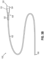
- FIGS. 3A-3B show an example of a lumen inspection device (100).
- Lumen inspection device (100) of this example includes a wire member (102) and a sealing member (120).
- Wire member (102) includes a distal end (104) and a proximal end (106), with a stop member (110) fixedly secured to distal end (104).
- stop member (110) has a cylindraceous shape.
- stop member (110) may be frustoconical or have any other suitable shape.
- Wire member (102) is formed of a flexible material having a high degree of tensile strength, such that wire member (102) is not longitudinally extensible.
- Wire member (102) also provides a substantial resistance to kinking or buckling during use of lumen inspection device (100) as described in greater detail below.
- wire member (102) may be formed of metal, polymer, and/or any other suitable material or combination of materials.
- wire member (102) comprises superelastic nitinol.
- Sealing member (120) of the present example is generally frustoconical in shape and includes a sleeve portion (122) and a flared portion (124) extending distally from sleeve portion (122).
- Sealing member (120) is formed of a polymeric material that is resiliently biased to form a tapered profile along flared portion (124).
- flared portion (124) may have a modulus of elasticity ranging from approximately 2.2 GPa to approximately 3.2 GPa; or more particularly approximately 2.7 GPa. Any suitable material or combination of materials may be used to form sealing member (120).
- sealing member (120) is formed of a material that is softer than the material forming sidewall of lumen (52).
- sealing member comprise polyethylene terephthalate (PET); while the material forming sidewall of lumen (52) comprises polyimide.
- the material forming flared portion (124) may have a wall thickness ranging from approximately 0.00010 inches to approximately 0.00025 inches; or more particularly approximately 0.00018 inches. Such wall thickness may ensure that flared portion (124) provides an appropriate balance between sealing against the sidewall of lumen (52) and deforming in response to contaminants (54) as described in greater detail below.
- Sealing member (120) is configured such that the distal end of flared portion (124) has a diameter that is approximately equal to, or slightly larger than, the diameter of a lumen in which lumen inspection device (100) will be used.
- lumen inspection device (100) may be assembled by inserting proximal end (106) of wire member (102) into flared portion (124) of sealing member (120), then sliding sealing member (120) distally along wire member (102) until sealing member (120) reaches distal end (104).
- sealing member (120) is slid distally along wire member (102) while wire member (102) remains stationary.
- wire member (102) is pulled proximally relative to sealing member (120) while sealing member (120) remains stationary.
- stop member (110) may engage the interior region of flared portion (124) as shown in FIG. 3B ; and thereby arrest further proximal movement of wire member (102) relative to sealing member (120).
- sleeve portion (122) extends along part of distal end (104) of wire member (102).
- sleeve portion (122) is bonded to the corresponding portion of wire member (102) and/or stop member (110) after reaching the state of assembly shown in FIG. 3B .
- an adhesive may be used to provide such bonding.
- sleeve portion (122) may include a heat-shrink material, such that heat may be applied to sleeve portion to cause sleeve portion (122) to shrink around and thereby grip the corresponding portion of wire member (102) and/or stop member (110).
- sleeve portion (122) may be thermally bonded directly to wire member (102) and/or stop member (110). Any other suitable techniques may be used to bond sleeve portion (122) to wire member (102) and/or stop member (110). In addition to mechanically securing sleeve portion (122) to wire member (102) and/or stop member (110), such bonding may prevent air from leaking between sleeve portion (122) and wire member (102) and/or between sleeve portion (122) and stop member (110).
- sleeve portion (122) is not bonded to wire member (102).
- engagement between stop member (110) and flared portion (124) may keep sealing member (120) and wire member (102) sufficiently together as lumen inspection device (100) is pulled through lumen (52) as described in greater detail below.
- sealing member (120) and wire member (102) may be integrally formed together as a monolithic unit.
- lumen inspection device (100) may be formed in any other suitable fashion using any other suitable processes.
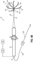
- FIGS. 4A-4B show an example of how lumen inspection device (100) may be used with catheter instrument (10).
- proximal end (106) of wire member (102) is inserted into lumen (52) via distal opening (50).
- Wire (102) is fed proximally along lumen (52) and passageway (13) until proximal end (106) exits handle (12) via port (14).
- sealing member (120) has not yet entered distal opening (50) into lumen (52).
- FIG. 4B the operator continues to pull wire member (102) such that sealing member (120) eventually enters lumen (52) via distal opening (50).
- a flow sensor (16) and pressure source (18) are coupled with port (14) during this procedure.
- Pressure source (18) is operable to communicate pressurized fluid (e.g., pressurized air) to lumen (52) via port (14) and passageway (13).
- Pressure source (18) may comprise a pump and/or any other suitable components.
- pressure source (18) may be configured to generate a fluid pressure of approximately 20 psi. Alternatively, any other suitable fluid pressure may be used.
- Flow sensor (16) is operable to sense flow of fluid within lumen (52).
- Port (14) is configured to provide a dynamic, fluid-tight fit about wire member (102).
- sealing member (120) Due to the sealing fit between sealing member (120) and the inner sidewall of lumen (52), the region of lumen (52) that is proximal to sealing member (120) will remain at a fluid pressure established by pressure source (18) until sealing member (120) encounters a contaminant in lumen (52) as described in greater detail below.
- Flow sensor (16) may operate continuously to detect any changes in the flow rate of fluid through lumen (52).
- a nominal amount of pressurized fluid may flow from lumen (52), through the interface between sealing member (120) and the inner sidewall of lumen (52) and/or through the interface between wire member (102) and port (14); and flow sensor (16) may detect such nominal flow.
- this nominal fluid flow rate may range from approximately 0 standard cubic centimeters per minute (SCCM) to approximately 15 SCCM.
- the fluid flow rate may substantially increase (e.g., spike) in the event that sealing member (120) encounters a contaminant (54) as described below.
- flow sensor (16) may be used to immediately take a baseline reading to determine the nominal flow rate of fluid through lumen (52).
- FIGS. 5A-5C and 6A-6C show sealing member (120) traversing a region of lumen (52) that includes a contaminant (54) on the sidewall of lumen (52).
- contaminant (54) may include a particle, such as biological material, manmade material, etc., in the sidewall of lumen (52) even after catheter instrument (10) has been cleaned and reprocessed for use in a second medical procedure after being used in a first medical procedure.
- Contaminant (54) may be adhered to the sidewall of lumen (52) or may be loosely contained in lumen (52).
- sealing member (120) is positioned distally in relation to contaminant (54).
- pressure source (18) maintains a substantially constant positive fluid pressure level in the region of lumen (52) proximal to sealing member (120).
- sealing member (120) is resiliently biased to form a tapered profile along flared portion (124), such that sealing member (120) resiliently bears against the sidewall of lumen (52) to thereby provide a sealing fit along the sidewall of lumen (52). With sealing member (120) providing a sealing fit along the sidewall of lumen (52), sealing member (120) prevents the pressurized fluid from escaping lumen (52) distally past sealing member (120).
- a seal (not shown) in port (14) prevents the pressurized fluid from escaping through the interface between port (14) and wire member (102).
- the operator may continue to pull lumen inspection device (100) proximally through lumen (52), with flow sensor (16) tracking the rate of fluid flow through lumen (52), to ensure that the flow rate is at a zero value or a nominal value, to thereby ensure that sealing member (120) is appropriately sealed against the sidewall of lumen (52).
- the resilience of sealing member (120) prevents the weight of wire member (102) and stop member (110) from causing sealing member (120) to collapse as lumen inspection device (100) traverses lumen (52). Flared portion (124) of sealing member (120) will thus maintain its frustoconical shape during transit along lumen, until sealing member (120) encounters a contaminant or other obstruction, etc., on the sidewall of lumen (52).
- sealing member (120) encounters contaminant (54). This causes a flared portion (124) to deform inwardly. This inward deformation of flared portion (124) effectively breaks the fluid seal between sealing member (120) and the sidewall of lumen (52). This break in the fluid seal allows pressurized fluid to pass from the region of lumen (52) proximal to sealing member (120) to the region of lumen (52) distal to sealing member, such that at least some pressurized fluid may ultimately escape via distal opening (50).
- the passage of pressurized fluid distally past sealing member (120) causes a sudden increase in the flow rate of fluid through lumen (52). This sudden increase in fluid flow rate is detected by flow sensor (16). The operator may continue to pull lumen inspection device (100) proximally through lumen (52).
- sealing member (120) has reached a longitudinal position where sealing member (120) has cleared contaminant (54) and sealing member (120) is now proximal to contaminant (54).
- the resilience of flared portion (124) has urged the previously-deformed part of flared portion (124) back into contact with the sidewall of lumen (52).
- the full circumference of flared portion (124) is now back in full contact with the sidewall of lumen (52), just like the state shown in FIG. 5A .
- the pressurized fluid again builds up in the region of lumen (52) that is proximal to sealing member (120).
- the fluid flow rate drops back down to the zero value or nominal value, where it was during the stage shown in FIG. 5A .
- the operator may continue to pull lumen inspection device (100) proximally through lumen (52), with flow sensor (16) tracking the rate of fluid flow through lumen (52), until sealing member (120) ultimately exits catheter instrument (10) via port (14).
- lumen inspection device (100) may translate at a substantially constant rate. In some versions, this is performed by a human operator manually pulling proximally on lumen inspection device via wire member (102) at a substantially constant rate of translation. In some other versions, a machine is used to pull lumen inspection device (100) proximally through catheter instrument (10) at a substantially constant rate of translation. In some variations, the rate of translation of inspection device (100) along catheter instrument (10) is variable. In some such versions, the variable rate of translation is known. Some versions of variable translation may also include proving different rates of translation of inspection device (100) along catheter instrument (10) based on the longitudinal position of inspection device (100) in catheter instrument (10).
- inspection device (100) may translate at a first constant rate as inspection device (100) traverses a first portion of the length of catheter instrument (10); then at a second constant rate as inspection device (100) traverses a second portion of the length of catheter instrument (10); then at a third constant rate as inspection device (100) traverses a third portion of the length of catheter instrument (10).
- any other suitable translation rates and algorithms may be used.
- FIG. 7 shows a graph (200) with a plot (210) of the fluid flow rate through lumen (52) during the stages of operation shown in FIGS. 5A-6C .
- the data shown by plot (210) may be provided via flow sensor (16).
- a first region (220) of plot (210) shows a nominal flow rate associated with the stage of operation depicted in FIGS. 5A and 6A . This nominal flow rate of first region (220) may be consistent with a baseline reading of the flow rate that is taken via flow sensor (16) when sealing member (120) initially enters lumen (52) via distal opening (50).
- a second region (222) of plot (210) shows a sudden increase in flow rate associated with the stage of operation depicted in FIGS. 5B and 6B .
- contaminant (54) causes deformation of flared portion (124), thereby partially breaking the seal between sealing member (120) and the sidewall of lumen (52), thereby allowing some of the pressurized fluid to flow distally past sealing member (120).
- the level to which the flow rate increases may be proportional to the size of contaminant (54), such that large contaminants may create large increases in flow rate and small contaminants (54) may create small increases in flow rates. It may therefore be possible to determine the size of contaminant (54) based on the level to which the flow rate increases.
- flow sensor (16) may be configured to provide an alert indicating the presence of contaminant (54) when a sudden increase in flow rate is indicated by the flow rate exceeding a certain threshold value (e.g., 30 SCCM). In some such cases, increases in the flow rate that still fall below the threshold value may be deemed negligible.
- a certain threshold value e.g. 30 SCCM
- a third region (224) of plot (210) shows the flow rate returning to the nominal level, consistent with the stage of operation depicted in FIGS. 5C and 6C .
- an alert feature is coupled with flow sensor (16) and is configured to alert an operator in the event that flow sensor (16) detects a sudden increase in the flow rate, such as the increase shown in second region (222) of plot (210).
- a sudden increase in the flow rate such as the increase shown in second region (222) of plot (210).
- an alert may include an audio alert, a visual alert, or combinations thereof.
- the alert may be provided in the form of a graphical and/or textual report; or may take any other suitable form.
- the operator may subject catheter instrument (10) to another cleaning process and/or other processing to try to remove contaminant (54) from lumen (52). The operator may then use lumen inspection device (100) to test catheter instrument (10) again, to see if the additional effort was successful in removing contaminant (54) from lumen (52).
- the level to which the flow rate increases during the stages represented in FIGS. 5B and 6B (and second region (222) of plot (210)) may indicate the size of contaminant (54).
- This size information may also be reported to the operator. The operator may tailor the response to the alert based on the reported size of contaminant (54).
- flow sensor (160) may enable the user to define a particle size threshold for detection; and may tailor the flow rate threshold value for alerts accordingly.
- some versions may be configured to differentiate between contaminants (54) in lumen (52) and kinks in lumen (52) based on changes in the flow rate.
- a detected contaminant (54) may trigger an alert for the operator to clear the contaminant (54); while a detected kink may not trigger an alert since contaminants may present greater risks to patients (e.g., in the form of embolic debris) than kinks when an instrument such as catheter instrument (10) is subsequently used in the patient.
- a kink in lumen (52) may be distinguished from a contaminant (54) in lumen based on the rapidity of the rise or fall of the flow rate increase.
- flow sensor (16) is used to detect sudden increases in the flow rate of fluid through lumen (52) that would tend to indicate the presence of contaminants (54) in lumen (52)
- some other versions may provide a pressure sensor that tracks the fluid pressure level within lumen (52).
- Such a pressure sensor may be used in addition to, or in lieu of, flow sensor (16).
- Such a pressure sensor may be used to detect sudden decreases in the pressure of fluid in lumen (52), with such sudden pressure decreases indicating presence of contaminants (54) in lumen (52) as sealing member (120) traverses lumen (52).
- FIGS. 8-10 show another example of a lumen inspection device (300) that may be used in the same manner as described above with respect to lumen inspection device (100). Except as otherwise described below, lumen inspection device (300) may be configured and operable like lumen inspection device (100).
- Lumen inspection device (300) of this example includes a wire member (302) and a sealing member (320).
- Wire member (302) includes a distal end (304) and a proximal end (306).
- a stop member (310) is fixedly secured to wire member (302), proximal to distal end (304).
- a distal segment (305) of wire member (302) thus extends between stop member (310) and distal end (304).
- Sealing member (320) of lumen inspection device (300) includes a first sleeve portion (322), a second sleeve portion (324) extending distally from first sleeve portion (322), and a flared portion (326) extending distally from second sleeve portion (324).
- Sealing member (320) is formed of a polymeric material that is resiliently biased to form a tapered profile along flared portion (326). Sealing member (320) is positioned along wire member (302) such that first sleeve portion (322) extends about a corresponding portion of wire member (302); and such that second sleeve portion (324) extends about stop member (310).
- First sleeve portion (322) may be bonded directly to wire member (302) thermally, via an adhesive, or in any other suitable fashion.
- second sleeve portion (324) may be bonded directly to stop member (310) thermally, via an adhesive, or in any other suitable fashion.
- sealing member (320) provides a tapered transition between sleeve portions (322, 324) in this example, sealing member (320) may instead provide a stepped transition or any other suitable kind of transition between sleeve portions (322, 324).
- Lumen inspection device (300) of this example is configured such that distal segment (305) of wire member (302) extends through flared portion (326) and extends further distally past sealing member (320).
- a lumen e.g., lumen (52), as described above
- distal segment (305) of wire member (302) extending distally past sealing member (320) distal segment (305) may assist in providing purchase or mechanical ground relative to sealing member (320) during such use of a tool to return flared portion (326) to the frustoconical shape.
- a method comprising: (a) inserting an elongate member of a lumen inspection device in a lumen of a medical instrument; (b) translating the lumen inspection device along the lumen of the medical instrument, the lumen inspection device including a sealing member, the sealing member resiliently bearing against a sidewall of the lumen as the lumen inspection device is translated along the lumen of the medical instrument; (c) activating a pressure source to pressurize a region of the lumen adjacent to the sealing member; and (d) monitoring a fluid property of the lumen during the acts of translating and activating, to thereby detect whether the sealing member deforms in response to an obstruction in the lumen.
- Example 1 The method of Example 1, the elongate member comprising a wire.
- Example 2 The method of Example 2, the wire comprising nitinol.
- Example 4 The method of Example 4, the catheter having an end effector with one or more electrodes.
- Example 5 The method of Example 5, the lumen having a distal opening at the end effector.
- the act of inserting comprising inserting the elongate member into a distal opening of the lumen, the distal opening being positioned at a distal end of a shaft assembly of the medical instrument.
- the lumen inspection device being configured such that a proximal portion of the lumen inspection device extends proximally from a handle of the medical instrument during at least part of the act of translating.
- Example 10 the handle including a port, the port forming a fluid tight seal around the elongate member during the act of translating.
- Example 11 The method of Example 11, the act of activating including activating a pressure source to communicate pressurized fluid to the lumen via the port.
- Example 14 The method of any of Examples 1 through 14, further comprising: (a) comparing the monitored fluid property to a baseline value; and (b) determining that the lumen contains an obstruction in response to the monitored fluid property exceeding the baseline value.
- Example 15 The method of any of Examples 1 through 15, further comprising: (a) determining that an obstruction is present in the lumen based on a change in the monitored fluid property; and (b) alerting an operator in response to determining that the obstruction is present in the lumen.
- An apparatus comprising: (a) an elongate wire having a proximal end and a distal end; (b) a stop member fixedly secured to the distal end of the elongate wire; and (c) a sealing member, the sealing member including a flared portion, the flared portion being resiliently biased to define a frustoconical shape, the sealing member having an interior region, the stop member being positioned within an interior region of the frustoconical shape, the stop member being configured to restrict distal translation of the sealing member relative to the elongate wire.
- Example 17 The apparatus of Example 17, the sealing member being slidably disposed on the elongate wire.
- a kit comprising: (a) a medical instrument having a shaft defining a lumen; (b) a lumen inspection device comprising: (i) a flexible elongate member having a distal end, and (ii) a sealing member at the distal end of the flexible elongate member, the lumen inspection device being configured to translate through the lumen, the sealing member being configured to resiliently bear against a sidewall of the lumen as the lumen inspection device translates through the lumen; (c) a pressure source operable to pressurize a region of the lumen adjacent to the sealing member as the lumen inspection device translates through the lumen; and (d) a fluid property monitor operable to monitor a fluid property of the lumen as the lumen inspection device translates through the lumen, to thereby detect whether the sealing member deforms in response to an obstruction in the lumen.
- the kit of Example 19 the medical instrument further including an end effector positioned at a distal end of the shaft, the end effector including one or more electrodes, the lumen having a distal opening at the end effector.
- any of the versions of the instruments described herein may include various other features in addition to or in lieu of those described above.
- any of the devices herein may also include one or more of the various features disclosed in any of the various references that are incorporated by reference herein.
- Various suitable ways in which such teachings may be combined will be apparent to those of ordinary skill in the art.
- Versions of the devices described above may have application in conventional medical treatments and procedures conducted by a medical professional, as well as application in robotic-assisted medical treatments and procedures.
- various teachings herein may be readily incorporated into a robotic surgical system such as the DAVINCI TM system by Intuitive Surgical, Inc., of Sunnyvale, California.
- DAVINCI TM system by Intuitive Surgical, Inc., of Sunnyvale, California.
- teachings herein may be readily combined with various teachings of U.S. Pat. No. 6,783,524, entitled "Robotic Surgical Tool with Ultrasound Cauterizing and Cutting Instrument," published August 31, 2004 , the disclosure of which is incorporated by reference herein.
- Versions described above may be designed to be disposed of after a single use, or they can be designed to be used multiple times. Versions may, in either or both cases, be reconditioned for reuse after at least one use. Reconditioning may include any combination of the steps of disassembly of the device, followed by cleaning or replacement of particular pieces, and subsequent reassembly. In particular, some versions of the device may be disassembled, and any number of the particular pieces or parts of the device may be selectively replaced or removed in any combination. Upon cleaning and/or replacement of particular parts, some versions of the device may be reassembled for subsequent use either at a reconditioning facility, or by an operator immediately prior to a procedure.
- reconditioning of a device may utilize a variety of techniques for disassembly, cleaning/replacement, and reassembly. Use of such techniques, and the resulting reconditioned device, are all within the scope of the present application.
- versions described herein may be sterilized before and/or after a procedure.
- the device is placed in a closed and sealed container, such as a plastic or TYVEK bag.
- the container and device may then be placed in a field of radiation that can penetrate the container, such as gamma radiation, x-rays, or high-energy electrons.
- the radiation may kill bacteria on the device and in the container.
- the sterilized device may then be stored in the sterile container for later use.
- a device may also be sterilized using any other technique known in the art, including but not limited to beta or gamma radiation, ethylene oxide, or steam.
Landscapes
- Health & Medical Sciences (AREA)
- Life Sciences & Earth Sciences (AREA)
- Surgery (AREA)
- Engineering & Computer Science (AREA)
- General Health & Medical Sciences (AREA)
- Pathology (AREA)
- Veterinary Medicine (AREA)
- Public Health (AREA)
- Nuclear Medicine, Radiotherapy & Molecular Imaging (AREA)
- Biomedical Technology (AREA)
- Heart & Thoracic Surgery (AREA)
- Medical Informatics (AREA)
- Molecular Biology (AREA)
- Animal Behavior & Ethology (AREA)
- Physics & Mathematics (AREA)
- Biophysics (AREA)
- Optics & Photonics (AREA)
- Radiology & Medical Imaging (AREA)
- Analytical Chemistry (AREA)
- Biochemistry (AREA)
- Immunology (AREA)
- Oral & Maxillofacial Surgery (AREA)
- Mechanical Engineering (AREA)
- Chemical & Material Sciences (AREA)
- General Physics & Mathematics (AREA)
- Otolaryngology (AREA)
- Plasma & Fusion (AREA)
- Cardiology (AREA)
- Infusion, Injection, And Reservoir Apparatuses (AREA)
- Measuring And Recording Apparatus For Diagnosis (AREA)
- Endoscopes (AREA)
- Measuring Pulse, Heart Rate, Blood Pressure Or Blood Flow (AREA)
- Media Introduction/Drainage Providing Device (AREA)
Priority Applications (1)
| Application Number | Priority Date | Filing Date | Title |
|---|---|---|---|
| EP23210176.6A EP4298987A3 (fr) | 2021-08-19 | 2022-08-18 | Appareil et procédé pour inspecter des microlumières de cathéter |
Applications Claiming Priority (1)
| Application Number | Priority Date | Filing Date | Title |
|---|---|---|---|
| US17/406,141 US12213846B2 (en) | 2021-08-19 | 2021-08-19 | Apparatus and method to inspect microlumen of catheter |
Related Child Applications (2)
| Application Number | Title | Priority Date | Filing Date |
|---|---|---|---|
| EP23210176.6A Division EP4298987A3 (fr) | 2021-08-19 | 2022-08-18 | Appareil et procédé pour inspecter des microlumières de cathéter |
| EP23210176.6A Division-Into EP4298987A3 (fr) | 2021-08-19 | 2022-08-18 | Appareil et procédé pour inspecter des microlumières de cathéter |
Publications (3)
| Publication Number | Publication Date |
|---|---|
| EP4137082A2 true EP4137082A2 (fr) | 2023-02-22 |
| EP4137082A3 EP4137082A3 (fr) | 2023-05-03 |
| EP4137082B1 EP4137082B1 (fr) | 2026-03-11 |
Family
ID=82942480
Family Applications (2)
| Application Number | Title | Priority Date | Filing Date |
|---|---|---|---|
| EP22190917.9A Active EP4137082B1 (fr) | 2021-08-19 | 2022-08-18 | Appareil et procédé pour inspecter la micro-lumière d'un cathéter |
| EP23210176.6A Pending EP4298987A3 (fr) | 2021-08-19 | 2022-08-18 | Appareil et procédé pour inspecter des microlumières de cathéter |
Family Applications After (1)
| Application Number | Title | Priority Date | Filing Date |
|---|---|---|---|
| EP23210176.6A Pending EP4298987A3 (fr) | 2021-08-19 | 2022-08-18 | Appareil et procédé pour inspecter des microlumières de cathéter |
Country Status (4)
| Country | Link |
|---|---|
| US (1) | US12213846B2 (fr) |
| EP (2) | EP4137082B1 (fr) |
| JP (1) | JP2023029302A (fr) |
| CN (1) | CN115707435A (fr) |
Citations (5)
| Publication number | Priority date | Publication date | Assignee | Title |
|---|---|---|---|---|
| US6783524B2 (en) | 2001-04-19 | 2004-08-31 | Intuitive Surgical, Inc. | Robotic surgical tool with ultrasound cauterizing and cutting instrument |
| US9314299B2 (en) | 2012-03-21 | 2016-04-19 | Biosense Webster (Israel) Ltd. | Flower catheter for mapping and ablating veinous and other tubular locations |
| US9907480B2 (en) | 2016-02-08 | 2018-03-06 | Biosense Webster (Israel) Ltd. | Catheter spine assembly with closely-spaced bipole microelectrodes |
| US10702177B2 (en) | 2016-08-24 | 2020-07-07 | Biosense Webster (Israel) Ltd. | Catheter with bipole electrode spacer and related methods |
| US10830682B1 (en) | 2019-05-24 | 2020-11-10 | Innovative Health | Test method development for mass flow identification of occluding small particulates in microlumens |
Family Cites Families (12)
| Publication number | Priority date | Publication date | Assignee | Title |
|---|---|---|---|---|
| US4721123A (en) * | 1986-10-23 | 1988-01-26 | Minntech Corporation | Catheter reprocessing system |
| AUPP537098A0 (en) * | 1998-08-20 | 1998-09-10 | Novapharm Research (Australia) Pty Ltd | Endoscope cleaning device |
| JP4633274B2 (ja) | 2000-02-17 | 2011-02-16 | オリンパス株式会社 | 内視鏡洗滌消毒装置 |
| US20040130332A1 (en) * | 2002-11-27 | 2004-07-08 | Harris Robert Jackson | Sliding pipe plug |
| US7752684B1 (en) | 2005-09-23 | 2010-07-13 | George Pieretti | Combination-cleaning tool and plunger |
| US8262645B2 (en) | 2007-11-21 | 2012-09-11 | Actuated Medical, Inc. | Devices for clearing blockages in in-situ artificial lumens |
| ES2820423T3 (es) | 2008-10-13 | 2021-04-21 | Asp Global Mfg Gmbh | Separador de canales de endoscopio |
| JP5547203B2 (ja) * | 2008-10-13 | 2014-07-09 | エシコン・インコーポレイテッド | 内視鏡再処理システムのための流体コネクタ |
| EP2198768A1 (fr) * | 2008-12-17 | 2010-06-23 | Nederlandse Organisatie voor toegepast-natuurwetenschappelijk Onderzoek TNO | Procédé d'inspection de l'intérieur d'un tuyau ou d'un tube creux en particulier pour un usage médical |
| US20160010139A1 (en) * | 2013-03-06 | 2016-01-14 | Ruhof Corporation | Devices and methods for testing the cleanliness of medical instruments |
| US20210170127A1 (en) | 2014-10-21 | 2021-06-10 | Jose Salinas | Method and apparatus for cleaning a tube |
| EP3562435B1 (fr) | 2016-12-30 | 2024-06-05 | SunMed Group Holdings, LLC | Dispositifs, systèmes et procédés de gestion de voies respiratoires artificielles |
-
2021
- 2021-08-19 US US17/406,141 patent/US12213846B2/en active Active
-
2022
- 2022-08-18 JP JP2022130501A patent/JP2023029302A/ja active Pending
- 2022-08-18 EP EP22190917.9A patent/EP4137082B1/fr active Active
- 2022-08-18 EP EP23210176.6A patent/EP4298987A3/fr active Pending
- 2022-08-19 CN CN202210998032.XA patent/CN115707435A/zh active Pending
Patent Citations (5)
| Publication number | Priority date | Publication date | Assignee | Title |
|---|---|---|---|---|
| US6783524B2 (en) | 2001-04-19 | 2004-08-31 | Intuitive Surgical, Inc. | Robotic surgical tool with ultrasound cauterizing and cutting instrument |
| US9314299B2 (en) | 2012-03-21 | 2016-04-19 | Biosense Webster (Israel) Ltd. | Flower catheter for mapping and ablating veinous and other tubular locations |
| US9907480B2 (en) | 2016-02-08 | 2018-03-06 | Biosense Webster (Israel) Ltd. | Catheter spine assembly with closely-spaced bipole microelectrodes |
| US10702177B2 (en) | 2016-08-24 | 2020-07-07 | Biosense Webster (Israel) Ltd. | Catheter with bipole electrode spacer and related methods |
| US10830682B1 (en) | 2019-05-24 | 2020-11-10 | Innovative Health | Test method development for mass flow identification of occluding small particulates in microlumens |
Also Published As
| Publication number | Publication date |
|---|---|
| CN115707435A (zh) | 2023-02-21 |
| EP4298987A3 (fr) | 2024-03-06 |
| EP4137082B1 (fr) | 2026-03-11 |
| EP4137082A3 (fr) | 2023-05-03 |
| JP2023029302A (ja) | 2023-03-03 |
| EP4298987A2 (fr) | 2024-01-03 |
| US20230056243A1 (en) | 2023-02-23 |
| US12213846B2 (en) | 2025-02-04 |
Similar Documents
| Publication | Publication Date | Title |
|---|---|---|
| JP7391562B2 (ja) | 電気生理学的マッピングカテーテル用の単極基準電極 | |
| JP6322210B2 (ja) | 標的化された挿管のためのデバイス、システム、および方法 | |
| US20150313633A1 (en) | Pericardial access device | |
| CN103096964B (zh) | 弯曲导管 | |
| US20090204005A1 (en) | Puncture resistant catheter for sensing vessels and for creating passages in tissue | |
| US20150313634A1 (en) | Pericardial access device | |
| US12336720B2 (en) | Shaver with blood vessel and nerve monitoring features | |
| JP2017504455A (ja) | ガス除去機能付き患者用アクセス機器 | |
| JP7532121B2 (ja) | 再挿入のための血塊回収装置の洗浄 | |
| EP4117503A1 (fr) | Procédés et systèmes de surveillance en temps réel et de nettoyage d'une lentille laparoscopique | |
| CN117769448A (zh) | 具有改善抽吸设计的吸入导管系统以及抽吸状况的评价 | |
| CN114585317B (zh) | 与导管组件一起使用的喇叭口插入构件 | |
| EP4137082A2 (fr) | Appareil et procédé pour inspecter la micro-lumière d'un cathéter | |
| US20200178945A1 (en) | Method and apparatus for minimally invasive amelioration of spinal epidural lipomatosis | |
| JP2021526412A (ja) | 内視鏡用超音波プローブおよび該プローブのためのシース | |
| WO2025260097A1 (fr) | Systèmes, procédés et kits pour obtenir et tester des échantillons de biomatière à partir de dispositifs endoscopiques | |
| Takayama | System and Procedure of Nonocclusion Type of Angioscopy |
Legal Events
| Date | Code | Title | Description |
|---|---|---|---|
| PUAI | Public reference made under article 153(3) epc to a published international application that has entered the european phase |
Free format text: ORIGINAL CODE: 0009012 |
|
| STAA | Information on the status of an ep patent application or granted ep patent |
Free format text: STATUS: THE APPLICATION HAS BEEN PUBLISHED |
|
| AK | Designated contracting states |
Kind code of ref document: A2 Designated state(s): AL AT BE BG CH CY CZ DE DK EE ES FI FR GB GR HR HU IE IS IT LI LT LU LV MC MK MT NL NO PL PT RO RS SE SI SK SM TR |
|
| PUAL | Search report despatched |
Free format text: ORIGINAL CODE: 0009013 |
|
| AK | Designated contracting states |
Kind code of ref document: A3 Designated state(s): AL AT BE BG CH CY CZ DE DK EE ES FI FR GB GR HR HU IE IS IT LI LT LU LV MC MK MT NL NO PL PT RO RS SE SI SK SM TR |
|
| RIC1 | Information provided on ipc code assigned before grant |
Ipc: A61B 1/12 20060101ALI20230329BHEP Ipc: A61B 18/14 20060101AFI20230329BHEP |
|
| STAA | Information on the status of an ep patent application or granted ep patent |
Free format text: STATUS: REQUEST FOR EXAMINATION WAS MADE |
|
| 17P | Request for examination filed |
Effective date: 20231030 |
|
| RBV | Designated contracting states (corrected) |
Designated state(s): AL AT BE BG CH CY CZ DE DK EE ES FI FR GB GR HR HU IE IS IT LI LT LU LV MC MK MT NL NO PL PT RO RS SE SI SK SM TR |
|
| GRAP | Despatch of communication of intention to grant a patent |
Free format text: ORIGINAL CODE: EPIDOSNIGR1 |
|
| STAA | Information on the status of an ep patent application or granted ep patent |
Free format text: STATUS: GRANT OF PATENT IS INTENDED |
|
| INTG | Intention to grant announced |
Effective date: 20251223 |
|
| GRAS | Grant fee paid |
Free format text: ORIGINAL CODE: EPIDOSNIGR3 |
|
| GRAA | (expected) grant |
Free format text: ORIGINAL CODE: 0009210 |
|
| STAA | Information on the status of an ep patent application or granted ep patent |
Free format text: STATUS: THE PATENT HAS BEEN GRANTED |
|
| AK | Designated contracting states |
Kind code of ref document: B1 Designated state(s): AL AT BE BG CH CY CZ DE DK EE ES FI FR GB GR HR HU IE IS IT LI LT LU LV MC MK MT NL NO PL PT RO RS SE SI SK SM TR |
|
| REG | Reference to a national code |
Ref country code: CH Ref legal event code: F10 Free format text: ST27 STATUS EVENT CODE: U-0-0-F10-F00 (AS PROVIDED BY THE NATIONAL OFFICE) Effective date: 20260311 Ref country code: GB Ref legal event code: FG4D |
|
| REG | Reference to a national code |
Ref country code: DE Ref legal event code: R096 Ref document number: 602022032006 Country of ref document: DE |
|
| REG | Reference to a national code |
Ref country code: IE Ref legal event code: FG4D |