EP4137085B1 - Capteur de température et électrode tridimensionnelle - Google Patents
Capteur de température et électrode tridimensionnelle Download PDFInfo
- Publication number
- EP4137085B1 EP4137085B1 EP22201230.4A EP22201230A EP4137085B1 EP 4137085 B1 EP4137085 B1 EP 4137085B1 EP 22201230 A EP22201230 A EP 22201230A EP 4137085 B1 EP4137085 B1 EP 4137085B1
- Authority
- EP
- European Patent Office
- Prior art keywords
- electrode
- temperature sensor
- temperature
- medical device
- disposed
- Prior art date
- Legal status (The legal status is an assumption and is not a legal conclusion. Google has not performed a legal analysis and makes no representation as to the accuracy of the status listed.)
- Active
Links
Images









Classifications
-
- A—HUMAN NECESSITIES
- A61—MEDICAL OR VETERINARY SCIENCE; HYGIENE
- A61B—DIAGNOSIS; SURGERY; IDENTIFICATION
- A61B18/00—Surgical instruments, devices or methods for transferring non-mechanical forms of energy to or from the body
- A61B18/04—Surgical instruments, devices or methods for transferring non-mechanical forms of energy to or from the body by heating
- A61B18/12—Surgical instruments, devices or methods for transferring non-mechanical forms of energy to or from the body by heating by passing a current through the tissue to be heated, e.g. high-frequency current
- A61B18/14—Probes or electrodes therefor
- A61B18/1492—Probes or electrodes therefor having a flexible, catheter-like structure, e.g. for heart ablation
-
- A—HUMAN NECESSITIES
- A61—MEDICAL OR VETERINARY SCIENCE; HYGIENE
- A61B—DIAGNOSIS; SURGERY; IDENTIFICATION
- A61B18/00—Surgical instruments, devices or methods for transferring non-mechanical forms of energy to or from the body
- A61B2018/00053—Mechanical features of the instrument of device
- A61B2018/00059—Material properties
- A61B2018/00071—Electrical conductivity
- A61B2018/00077—Electrical conductivity high, i.e. electrically conducting
-
- A—HUMAN NECESSITIES
- A61—MEDICAL OR VETERINARY SCIENCE; HYGIENE
- A61B—DIAGNOSIS; SURGERY; IDENTIFICATION
- A61B18/00—Surgical instruments, devices or methods for transferring non-mechanical forms of energy to or from the body
- A61B2018/00053—Mechanical features of the instrument of device
- A61B2018/00059—Material properties
- A61B2018/00071—Electrical conductivity
- A61B2018/00083—Electrical conductivity low, i.e. electrically insulating
-
- A—HUMAN NECESSITIES
- A61—MEDICAL OR VETERINARY SCIENCE; HYGIENE
- A61B—DIAGNOSIS; SURGERY; IDENTIFICATION
- A61B18/00—Surgical instruments, devices or methods for transferring non-mechanical forms of energy to or from the body
- A61B2018/00053—Mechanical features of the instrument of device
- A61B2018/00107—Coatings on the energy applicator
-
- A—HUMAN NECESSITIES
- A61—MEDICAL OR VETERINARY SCIENCE; HYGIENE
- A61B—DIAGNOSIS; SURGERY; IDENTIFICATION
- A61B18/00—Surgical instruments, devices or methods for transferring non-mechanical forms of energy to or from the body
- A61B2018/00053—Mechanical features of the instrument of device
- A61B2018/0016—Energy applicators arranged in a two- or three dimensional array
-
- A—HUMAN NECESSITIES
- A61—MEDICAL OR VETERINARY SCIENCE; HYGIENE
- A61B—DIAGNOSIS; SURGERY; IDENTIFICATION
- A61B18/00—Surgical instruments, devices or methods for transferring non-mechanical forms of energy to or from the body
- A61B2018/00053—Mechanical features of the instrument of device
- A61B2018/00214—Expandable means emitting energy, e.g. by elements carried thereon
- A61B2018/0022—Balloons
-
- A—HUMAN NECESSITIES
- A61—MEDICAL OR VETERINARY SCIENCE; HYGIENE
- A61B—DIAGNOSIS; SURGERY; IDENTIFICATION
- A61B18/00—Surgical instruments, devices or methods for transferring non-mechanical forms of energy to or from the body
- A61B2018/00053—Mechanical features of the instrument of device
- A61B2018/00214—Expandable means emitting energy, e.g. by elements carried thereon
- A61B2018/00267—Expandable means emitting energy, e.g. by elements carried thereon having a basket shaped structure
-
- A—HUMAN NECESSITIES
- A61—MEDICAL OR VETERINARY SCIENCE; HYGIENE
- A61B—DIAGNOSIS; SURGERY; IDENTIFICATION
- A61B18/00—Surgical instruments, devices or methods for transferring non-mechanical forms of energy to or from the body
- A61B2018/00315—Surgical instruments, devices or methods for transferring non-mechanical forms of energy to or from the body for treatment of particular body parts
- A61B2018/00505—Urinary tract
- A61B2018/00517—Urinary bladder or urethra
-
- A—HUMAN NECESSITIES
- A61—MEDICAL OR VETERINARY SCIENCE; HYGIENE
- A61B—DIAGNOSIS; SURGERY; IDENTIFICATION
- A61B18/00—Surgical instruments, devices or methods for transferring non-mechanical forms of energy to or from the body
- A61B2018/00571—Surgical instruments, devices or methods for transferring non-mechanical forms of energy to or from the body for achieving a particular surgical effect
- A61B2018/00577—Ablation
-
- A—HUMAN NECESSITIES
- A61—MEDICAL OR VETERINARY SCIENCE; HYGIENE
- A61B—DIAGNOSIS; SURGERY; IDENTIFICATION
- A61B18/00—Surgical instruments, devices or methods for transferring non-mechanical forms of energy to or from the body
- A61B2018/00636—Sensing and controlling the application of energy
- A61B2018/00773—Sensed parameters
- A61B2018/00791—Temperature
- A61B2018/00797—Temperature measured by multiple temperature sensors
-
- A—HUMAN NECESSITIES
- A61—MEDICAL OR VETERINARY SCIENCE; HYGIENE
- A61B—DIAGNOSIS; SURGERY; IDENTIFICATION
- A61B18/00—Surgical instruments, devices or methods for transferring non-mechanical forms of energy to or from the body
- A61B2018/00636—Sensing and controlling the application of energy
- A61B2018/00773—Sensed parameters
- A61B2018/00791—Temperature
- A61B2018/00821—Temperature measured by a thermocouple
Definitions
- a medical device can be threaded through a vasculature of a patient to a site where the diagnostic, therapeutic, mapping, and/or ablative procedure to diagnose and/or correct the condition is performed.
- sensors e.g., electrodes
- a device e.g., electromagnetic field generator
- the electrode 100 can be a sensing electrode, receiving electrical signals from a tissue and transmitting them to a computer for further analysis.
- the electrode 100 can be an ablation electrode, where electrical signals are provided to the electrode 100, causing the electrode 100 to be heated.
- electrical traces can be disposed underneath the electrode 100, which can form the temperature sensor 102.
- the temperature sensor 102 can be a trace temperature sensor, which includes conductive electrical traces that are formed from an additive and/or subtractive manufacturing process.
- a first conductor lead 104-1 and a second conductor lead 104-2 can be disposed underneath the electrode 100.
- a thermocouple conductor 106 can be disposed underneath the electrode 100.
- the first conductor lead 104-1, second conductor lead 104-2, and/or the thermocouple conductor 106 can be disposed between a shaft on which the electrode 100 is disposed and the electrode 100.
- power can be provided to the electrode 100 via the first conductor lead 104-1 and the second conductor lead 104-2.
- the electrode 100 can be heated to a first temperature.
- a therapy can be performed by placing the electrode 100 on a tissue, such as a tissue of the heart, and heating the electrode to a particular temperature by providing power via the first conductor lead 104-1 and the second conductor lead 104-2.
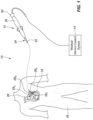
- power can be provided to the electrode 100 via the first conductor lead 104-1 and the second conductor lead 104-2, causing the electrode 100 to be heated to the particular temperature. Control over the power provided to the electrode 100 from the first conductor lead 104-1 and the second conductor lead 104-2 can be modulated via the medical device control system 14 discussed in Fig. 1 .
- a signal can be received via the electrode 100.
- the electrode 100 can be placed in contact with a tissue.
- the tissue can generate an electrical signal, which can be received by the electrode 100 and transferred to a computer (e.g., medical device control system 14) via the first conductor lead 104-1 and/or the second conductor lead 104-2.
- a computer e.g., medical device control system 14
- the first conductor lead 104-1 can be a multipurpose conductor.
- the first conductor lead 104-1 can supply power to the electrode 100 and/or receive energy from the electrode 100 in the form of electrical signals generated by the heart and/or electricity transferred through the patient via the external patch.
- the first conductor lead 104-1 can also complete a circuit of the temperature sensor 102.
- the thermocouple conductor 106 can convert the change in temperature to an electrical voltage, which can be analyzed to determine the temperature of the temperature sensor 102.
- the temperature sensor 102 can be a thermocouple formed by the first conductor lead 104-1 and the thermocouple conductor 106.
- thermocouple is given as an example of a temperature sensor herein, the temperature sensor can be any other type of temperature sensor, including thermistors, resistance temperature detectors, electrical thermometers, bimaterial thermometers, etc.
- thermistors can sense temperature based on resistance and can be formed via printing.
- Electrical thermometers can determine temperature as a result of a resistivity change due to temperature and can be formed via printing.
- Bimaterial thermometers can determine temperature via detection of mechanical motion based on different thermal expansion coefficients.
- the electrode and associated temperature sensor can be incorporated into a three-dimensional base, as further discussed in relation to Fig. 3A .
- the three-dimensional electrode 200 can include a perimeter interface 208 between the three-dimensional profile portion 206 and the planar base portion 204.
- the perimeter interface 208 is oblong in shape.
- the perimeter interface 208 can be any shape, including circular, square, rectangular, polygonal, triangular, elliptical, etc.
- the planar base portion 204 is depicted, in some embodiments, there may be no planar base portion 204.
- the three-dimensional base 202 can be formed from a deformable material.
- the three-dimensional base 202 can be formed from a metal, polymer, or other type of material, which can be deformed via application of heat and/or pressure to the material.
- the three-dimensional profile portion 206 can be formed by casting the three-dimensional base 202 and/or pressing the three-dimensional base 202 (e.g., via tool and die) to form the three-dimensional profile portion 206.
- the polymer can be formed such that the three-dimensional profile portion 206 is formed in the three-dimensional base 202.
- the polymer can be cast such that the three-dimensional base 202 includes the three-dimensional profile portion 206 and/or the polymer can be heated and/or pressure can be applied to the polymer to form the three-dimensional profile portion 206.
- the three-dimensional base 202 can be formed through an additive manufacturing process.
- the three-dimensional base 202 can be formed by depositing material onto a mold through an additive process, such as printing, chemical vapor deposition, etc.
- the material can be cured and the mold can be released from the material, thus forming the three-dimensional base 202.
- the three-dimensional base can be formed via a subtractive process (e.g., laser etching, chemical etching, machining, etc.).
- a tie layer 212 can be disposed between the three-dimensional base 202 and the electrode 210, which can help to bond the electrode 210 to the three-dimensional base 202.
- the tie layer 212 can be formed from a conductive material such as a metal.
- the tie layer 212 can be formed from a metal such as nickel, sputtered chrome, etc.
- a dielectric layer can be disposed beneath the tie layer, insulating the electrode 210 and the dielectric layer from the three-dimensional base 202.
- the electrode 210 can be formed as described in U.S. Application no. 15/331,562 .
- an electrode and/or temperature sensor can be formed with a three-dimensional profile using additive methods. In some embodiments, however, the electrode and/or temperature sensor can be formed with a three-dimensional profile via pressing a substrate blank, as discussed below.
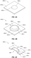
- Fig. 4A is an isometric view of a substrate blank 220-a for use in the formation of a three-dimensional electrode as further depicted in Figs. 4A and 4B in accordance with embodiments of the present disclosure.
- the substrate blank 220-a can be formed from a planar piece of material 222-a.
- the planar piece of material 222-a is square in shape, although the planar piece of material 222-a can be of another shape (e.g., circular, triangular, rectangular, oblong, etc.).
- a sketch 224-a is depicted on the surface of the planar piece of material 222-a, which in some embodiments can outline a face 226-a where an electrode can be disposed.
- the face 226-a contained by the sketch 224-a can be prepared (etched, coated, etc.) in order to prepare the area for application of one or more layers of coatings, which can form an electrode.
- an electrode can be disposed on the face 226-a contained by the sketch 224-a via an additive manufacturing process (e.g., printing, vapor deposition, etc.), as discussed herein.
- an electrode can be disposed on the face 226-b contained by the sketch 224-b.
- an electrode can be formed on a portion of the face 226-b via an additive manufacturing process, as previously discussed herein.
- the electrode can be elevated from a surface of the planar piece of material 222-b. This can create a stand-off to a geometry of a medical device on which the electrode is disposed, allowing for a better contact between the electrode disposed on the face 226-b and tissue.
- the electrode can be formed on the face 226-b, the first profile portion 232-1, the profile interface 234-b, and/or the second profile portion 232-2.
- the electrode can be disposed on one or more portions of the three-dimensional profile portion 228-b.
- the electrode can be disposed on portions of the three-dimensional profile portion 228-b that extend upward from the planar piece of material 222-b.
- the electrode can be formed on the face 226-b, the first profile portion 232-1, the profile interface 234-b, and/or the second profile portion 232-2 via an additive manufacturing process.
- Fig. 4C is an isometric cross-sectional view of the substrate blank 220-c depicted in Fig. 4B , in accordance with embodiments of the present disclosure.
- the substrate blank 220-c includes the planar piece of material 222-c, from which extends the three-dimensional profile portion 228-c.
- the perimeter interface 230-c can exist between an interface of the three-dimensional profile portion 228-c and the planar piece of material 222-c.
- the three-dimensional profile portion 228-c can have a stepped profile. For example, as depicted in Fig.
- the three-dimensional profile portion 228-c can have the first stepped profile portion 232-1 and the second stepped profile portion 232-2, which can be separated by the profile interface 234-c.
- the second stepped profile portion 232-2 can extend upwards from the profile interface 234-c to the face 226-c.
- a profile space 236 can be defined beneath the three-dimensional profile portion 228-c.
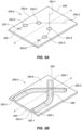
- Fig. 5B is an isometric view of the substrate blank 250-b depicted in Fig. 5A with three-dimensional profile portions 260-1, 260-2 formed in the substrate blank 250-b, in accordance with embodiments of the present disclosure.
- the substrate blank 250-b can be pressed and/or constructed to form the three-dimensional profile portions 260-1, 260-2.
- the three-dimensional profile portions 260-1, 260-2 can be formed along the three-dimensional profile sketches 254-1, 254-2.
- the high density electrode mapping catheter 268 can include a flexible tip portion 270 that forms a flexible array of microelectrodes 272.
- the high density electrode mapping catheter 270 can include a catheter shaft, not depicted, from which the flexible tip portion 270 extends.
- the flexible tip portion 270 can form a planar array (or 'paddle' configuration) of microelectrodes 274, which comprises four side-by-side, longitudinally-extending arms 274, 276, 278, 280, which can form a flexible framework on which the microelectrodes 272 are disposed.
- the four microelectrode-carrier arms comprise a first outboard arm 274, a second outboard arm 276, a first inboard arm 278, and a second inboard arm 280. These arms can be laterally separated from each other.
- Each of the four arms can carry a plurality of microelectrodes 272.
- each of the four arms can carry microelectrodes 272 spaced along a length of each of the four arms.
- the high density electrode mapping catheter 268 depicted in Fig. 6 includes four arms, the high density electrode mapping catheter 268 could comprise more or fewer arms.
- the high density electrode mapping catheter 268 depicted in Fig. 6 includes 16 electrodes (e.g., 4 microelectrodes on each of the first outboard arm 278 and second outboard arm 280 and 4 microelectrodes on each of the first inboard arm 274 and second inboard arm 276)
- the catheter can include more or fewer than 16 electrodes.
- the first outboard arm 278 and second outboard arm 280 can include more or fewer than 4 microelectrodes and the first inboard arm 274 and second inboard arm 276 can include more or fewer than 4 microelectrodes).
- the microelectrodes 272 can include a temperature sensor such as that depicted and discussed in relation to Figs. 2 to 3B .
- a temperature sensor can be disposed underneath one or more of the microelectrodes 272 and/or formed within one or more of the microelectrodes 272. The temperature sensor can thereby measure a temperature of one or more of the microelectrodes 272.
- one temperature sensor can be associated with each microelectrode 272. For example, one temperature sensor can be disposed beneath, within, and/or on top of each microelectrode 272.
- the microelectrodes 272 can have a surface area of 0.2 millimeters 2 , which can be a size associated with a diagnostic electrode, although the microelectrodes 272 can have a surface area that is greater than or smaller than 0.2 millimeters 2 .
- an ablation electrode can be of a larger size than 0.2 millimeters 2 .
- the electrodes 312-1, 312-2, 312-3, 312-4 can include a temperature sensor such as that depicted and discussed in relation to Figs. 2 to 3B .
- a temperature sensor can be disposed underneath one or more of the electrodes 312-1, 312-2, 312-3, 312-4 and/or formed within one or more of the electrodes 312-1, 312-2, 312-3, 312-4. The temperature sensor can thereby measure a temperature of one or more of the electrodes 312-1, 312-2, 312-3, 312-4.
- the electrodes 312-1, 312-2, 312-3, 312-4 can be three-dimensional electrodes, such as those discussed in relation to Figs. 4A to 5B .
- the electrodes 312-1, 312-2, 312-3, 312-4 can extend upwards from a surface of each one of the radially expanding members 306-1, 306-2, 306-3, 306-4.
- the electrodes 312-1, 312-2, 312-3, 312-4 can be formed as discussed in relation to Figs. 2 to 5B .
- Direct-write electronic additive manufacturing such as aerosol jet, micropen and/or ink-jet application of conductive traces and dielectrics, and materials such as high conductivity inks, can be used in embodiments of the present disclosure to enable the replacement of higher cost/labor intensive EP catheter components.
- These may include elements such as conductors and rings, but also more complicated elements such as temperature sensors, magnetic pick-up coils and force sensors.
- temperature sensors such as the thermocouples 330-1a, 330-2a and/or the RTDs 332-1a, 332-2a can be disposed on the EP catheter components (e.g., catheter tube 322a).
- the location and distribution of temperature sensors in the array may be optimized for prediction of both contact area and to provide initial / boundary conditions for thermal modeling of lesion depth, size etc.
- the temperature sensing element can be resistance based (e.g., RTD) or voltage based (e.g., thermocouple).
- RTD resistance temperature detectors
- the geometry of the RTD resistive formulation can be optimized for temperature sensitivity and signal stability.
- the temperature sensing element can be comprised of a printed union of two dissimilar metals known to produce a temperature dependent open circuit voltage (Seebeck effect). These can include metal combinations of standard thermocouples including types E, 3, K, R, S and T. In addition, metal combinations can also include less conventional metal combinations that are more amenable to direct write printing.
- thermocouple can be platinum and gold.
- processing electronics can also include the necessary temperature compensation for any additional dissimilar metal combinations within the circuitry.
- the catheter tube 322b can define a central lumen that extends through the catheter tube and/or can be solid.
- the catheter tube 322b can be a catheter shaft and/or a portion of a catheter shaft in some embodiments.
- the catheter tube 322b can be connected to a catheter shaft (e.g., a distal end of the catheter shaft).
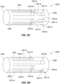
- the catheter tube 322b can include a plurality of temperature sensors 330-lb, 330- 2b, 332-lb, 332-2b, in some embodiments.
- the catheter tube 322b can be a portion of a catheter shaft and/or connected to a portion of a catheter shaft.
- the catheter tube 322b can have a proximal end 324b and a distal end 326b, and can extend along a longitudinal axis and can define a lumen that extends therethrough.
- the temperature sensors 330-lb, 330-2b, 332-lb, 332-2b can be disposed on an exterior surface 328b of the catheter tube 322b.
- the temperature sensors 330-lb, 330-2b can be thermocouples.
- the thermocouples 330-lb, 330-2b can be connected to a processing unit (e.g., computer) via a first lead and a second lead.
- the thermocouple 330-lb can be connected to the processing unit via a first lead 334-lb and a second lead 334-2b.
- a first thermocouple element 338-lb can be electrically coupled with the first lead 334-lb and a second thermocouple element 338-2b can be electrically coupled with the second lead 334-2b.
- thermocouple element 338-lb can be electrically coupled with the second thermocouple element 338-2b.
- temperature sensors 332-lb, 332-2b can be connected to the processing unit via leads 336-lb, 336-2b.
- the temperature sensors 332-la', 332-2a', 332-lb', 332-2b' may not be disposed in a serpentine fashion, such as that depicted in Figs. 8A and 8B .
- the temperature sensors 332-la', 332-2a', 332-lb', 332-2b' are depicted as being disposed in a square configuration.
- the temperature sensors 332-la', 332-2a', 332-lb', 332-2b' can be disposed in other shaped configurations, in some embodiments.
- the temperature sensors 332-la', 332-2a', 332-lb', 332-2b' can be disposed in a triangular configuration, rectangular configuration, circular configuration, oval configuration, etc.
- the hollow cylindrical body 354 can define a lumen 358 in which a member (e.g., elongate tubular member, catheter tube 360) can be inserted.
- a member e.g., elongate tubular member, catheter tube 360
- the member can be any number of devices.
- the member can be an elongate member, such as an elongate tubular member that includes a fluid lumen, etc.
- the member is discussed as a catheter tube 360 herein.
- the catheter tube 360 can include features that are similar or the same as those discussed in relation to Fig. 8 .
- the catheter tube 360 can include a plurality of temperature sensors 362-1, 362-2, 362-3, 362-4, hereinafter referred to in the plural as temperature sensors 362, disposed in an array on an exterior surface of the catheter tube 360.
- the temperature sensors 362 can be disposed next to an interior surface of the ablation tip 352.
- the diameter of the catheter tube 360 can be correlated with an interior diameter of the lumen 358 and an inner wall 364 of the hollow cylindrical body 354, such that the temperature sensors 362 abut the inner wall 364 of the ablation tip 352.
- the catheter tube 360 can have the temperature sensors 362 disposed on the catheter tube 360 and the catheter tube 360 can be inserted into the lumen 358 of the ablation tip 352, placing the temperature sensors 362 in contact with the inner wall 364 of the ablation tip 352. Accordingly, as the ablation tip 352 is heated to perform an ablation, the temperature sensors 362 can measure a temperature of the ablation tip 352.
- the temperature sensors 362 can be thermocouples and/or RTDs (e.g., thermistors), among other types of temperature sensors.
- the temperature sensors 362 can be distributed across a surface of the catheter tube 360, such that a temperature across multiple areas of the ablation tip 352 can be determined.
- a thermally insulating layer can be disposed between the surface of the catheter tube 360 and the temperature sensors 362 and/or the catheter tube 360 can be formed from a thermally insulating material. Accordingly, this can increase an accuracy at which the temperature sensors 362 collect temperature data from the ablation tip 352, because the main source of thermal activity measured by the temperature sensors 362 will come from the ablation tip 352 and not the catheter tube 360, which is thermally insulated from the temperature sensors 362.
- Fig. 10 is a side view of a temperature enabled ablation balloon 380, in accordance with embodiments of the present disclosure.
- the temperature enabled ablation balloon 380 can be disposed about a catheter shaft 384, which extends along an elongate axis defined by line cc, and can be inflated with a cryogenic fluid to perform a pulmonary vein isolation, in some embodiments.
- a plurality of temperature sensors 386-1, 386-2, 386-3, 386-4, hereinafter referred to in the plural as temperature sensors 386 can be disposed on the ablation balloon 382.
- the temperature sensors 386 can be thermocouples and/or RTDs, among other types of temperature sensors.
- the temperature sensors 386 can be printed on an exterior surface and/or an interior surface of the ablation balloon 382.
- Fig. 12 is a diagrammatic isometric view of a temperature enabled catheter tube 420 with temperature sensors 422-1, 422-2 that share a common lead 424 (e.g., ground), in accordance with embodiments of the present disclosure.
- the temperature enabled catheter tube 420 can include features that are similar to or the same as those discussed herein, for example, in relation to Fig. 8 .
- the temperature sensors 422-1, 422-2 can be RTDs, however, the temperature sensors 422-1, 422-2 can be other types of temperature sensors in some embodiments.
- the temperature sensors 422-1, 422-2 can share a common lead 424 in some embodiments.
- each temperature sensor 422-1, 422-2 can be connected to a processing unit via a pair of leads.
- Fig. 13 is a diagrammatic isometric view of a temperature enabled catheter tube 430 with a temperature sensor 432 in communication with a computing device 436, in accordance with embodiments of the present disclosure.
- the temperature sensor 432 can be disposed on the catheter tube 430 and can be a thermocouple 432.
- the temperature sensor 332 can be an RTD (e.g., thermistor) or another type of temperature sensor.
- the thermocouple 432 can include a first thermocouple element 434-1 and a second thermocouple element 434-2.
- the first thermocouple element 434-1 and the second thermocouple element 434-2 can be formed from dissimilar metals and one of the metals can be a type of metal that produces a temperature dependent response.
- a terminal end of the source lead 456-1, 456-2,..., 456-8 can include a source pad, as depicted, which can allow for additional leads to be coupled to a respective one of the source leads 456-1, 456-2,..., 456-8.
- additional leads can be coupled to respective ones of the source leads 456-1, 456-2,..., 456-8 and can be extend proximally along a length of a catheter shaft and can be connected to a power source to provide power to one or more of the temperature sensors 452-1, 452-2,..., 452-8.
- a source lead 456-1 (e.g., source contact pad) can include a distally extending source lead 458, which can be electrically coupled with the source lead 456-1 and the temperature sensor 452-1 and can provide power to the temperature sensor 452-1.
- a proximally extending return lead 460 can extend from the temperature sensor 452-1 and can be electrically coupled with the common return lead 454 (e.g., common return contact pad).
- a measurement of resistance can be made based on an input signal provided to each one of the temperature sensors 452-1, 452-2,..., 452-8 and a return signal provided via the common return lead 454. Based on the measurement of resistance, a temperature at each one of the temperature sensors 452-1, 452-2,..., 452-8 can be determined.
- the array 450 of temperature sensors 452-1, 452-2,..., 452-8 can be disposed on a substrate 462.
- the substrate 462 can be a surface associated with a catheter ablation tip.
- the substrate 462 can be an interior surface of an ablation tip and/or an exterior surface of the ablation tip.
- the substrate 462 can be a planar sheet of material (e.g., film) on which the temperature sensors 452-1, 452-2,..., 452-8 and associated leads are formed.
- the substrate 462 can be adhered to an interior or exterior surface of the catheter ablation tip.
- Fig. 15 is a side view of a radial ablation tip 472, according to various embodiments of the present disclosure.
- the radial ablation tip 472 can be connected to a distal end of a catheter shaft (not depicted).
- the radial ablation tip 472 can be similar to that included in the EnligHTN TM Multi-Electrode Renal Denervation System, produced by St. Jude Medical, further discussed in U.S. Application no. 14/258,407.
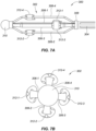
- the radial ablation tip 472 can include a plurality of radially expanding members 474-1, 474-2, 474-3, 474-4 that extend distally and axially from a connector (not depicted), which is attached to the distal end of the shaft.
- each one of the radially expanding members 474-1, 474-2, 474-3, 474-4 can include one or more electrodes 478 disposed thereon. Only electrode 478 is depicted for ease of clarity. As the radially expanding members 474-1, 474-2, 474-3, 474-4 expand, the electrode(s) 478 can contact a lumen in which the radial ablation tip 472 is disposed. For example, the radial ablation tip 472 can be disposed in a renal artery and the radial ablation tip 472 can be expanded to cause the electrode(s) 478 to contact an inner wall of the renal artery. Upon contact with the inner wall, the electrode(s) 478 can perform a sensing and/or therapeutic function.
- the electrode(s) 478 can sense electrical signals passing along the renal artery and/or can perform an ablation to the renal artery.
- the electrode(s) 478 can be three-dimensional electrodes, such as those discussed in relation to Figs. 4A to 5B .
- the electrode(s)s 478 can extend upwards from a surface of each one of the radially expanding members 474-1, 474-2, 474-3, 474-4.
- the electrode(s) 478 can be formed as discussed in relation to Figs. 2 to 5B and/or in relation to Figs. 16A to 16J .
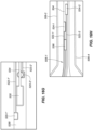
- Fig. 16G depicts a dielectric coating 528 disposed over the temperature sensor 516 depicted in Fig. 16B , with an electrode 530 disposed over the dielectric coating 528, in accordance with embodiments of the present disclosure.
- the electrode 530 can be formed from a conductive material.
- the electrode 530 can be formed from platinum.
- the electrode 530 can be deposited on top of the dielectric coating 528, which insulates the electrode 530 from the temperature sensor 516, and its first and second electrical conductors 522-1', 522-2'.
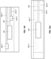
- Fig. 16I depicts a dielectric coating disposed over the areas surrounding the electrode 530, in accordance with embodiments of the present disclosure.
- a dielectric material can be disposed over portions surrounding the electrode 530.
- a dielectric material 540 can be disposed over the electrode lead 534' and/or conductors 522-1", 522-2" and/or electrical contacts 520-1", 520-2".
- the electrode 530 itself may remain uncoated with the dielectric material.
- the electrode 530' has been coated with a highly conductive material.
- the electrode 530' can be coated with gold, in some embodiments.
- the conductive layering might be other materials in lieu of or in addition to gold.
- some embodiments can include an electrode that can protrude from a surface of a substrate associated with a medical device.
- the substrate can be disposed on a distal portion of a catheter.
- the substrate can be disposed on an end effector located at a distal portion of the catheter.
- the electrode can be include a spherical cap and/or can be configured as a cylindrical shape, versus a planar circle and/or oval, which can lower the overall impedance, help ensure better tissue contact, and can be accomplished with minimal extra process steps and/or harsh chemicals.
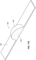
- the elevated electrode 542 can be configured as a spherical cap, in some embodiments, as depicted in Figs. 17A and 17B .
- the elevated electrode 542 can be a hemisphere and/or a partial hemisphere that is attached to the substrate.
- a planar portion of the hemisphere can be attached to the substrate, such that the curved hemispherical portion of the elevated electrode 542 extends above the substrate 544.
- the conductive coating 550 can have a thickness in a range from 2 microns to 4 microns, although embodiments are not so limited and the thickness can be lesser or greater than the provided range. In some embodiments, the conductive coating 550 can have a thickness in a range from 1 microns to 50 microns.
- Fig. 18 depicts a graphical chart 556 representing a difference in impedance of a traditional type electrode with a height of 4 microns versus that of an elevated electrode with a height of 150 microns, in accordance with embodiments of the present disclosure.
- the graphical chart indicates that an elevated electrode with a height of 150 microns, in accordance with embodiments of the present disclosure, can provide for an impedance that is lower than a traditional type of electrode with a height of 4 microns.
- the 150 micron elevated electrode can have a same surface area as the 4 micron electrode, while having a lower impedance. This is proven to be especially true for electrodes with a smaller surface area, as depicted by the graphical chart 556.
- embodiments of the present disclosure can provide for an elevated electrode that can collect electrical signals from a particular area, while further providing for an impedance level associated with the electrode that is low, resulting in accurate and usable electrograms.
Landscapes
- Health & Medical Sciences (AREA)
- Life Sciences & Earth Sciences (AREA)
- Surgery (AREA)
- Engineering & Computer Science (AREA)
- Plasma & Fusion (AREA)
- Medical Informatics (AREA)
- Otolaryngology (AREA)
- Physics & Mathematics (AREA)
- Cardiology (AREA)
- Biomedical Technology (AREA)
- Heart & Thoracic Surgery (AREA)
- Nuclear Medicine, Radiotherapy & Molecular Imaging (AREA)
- Molecular Biology (AREA)
- Animal Behavior & Ethology (AREA)
- General Health & Medical Sciences (AREA)
- Public Health (AREA)
- Veterinary Medicine (AREA)
- Surgical Instruments (AREA)
- Measurement And Recording Of Electrical Phenomena And Electrical Characteristics Of The Living Body (AREA)
Claims (13)
- Dispositif médical, comprenant :une tige allongée s'étendant le long d'un axe longitudinal de tige et comprenant une partie proximale de tige et une partie distale de tige ;un embout d'ablation (350, 352 ; 400, 402 ; 472, 500) connecté à la partie distale de tige,l'embout d'ablation (350, 352 ; 400, 402 ; 472, 500) étant une coque conductrice disposée par-dessus une extrémité de la partie distale de tige ; etun capteur de température (330-1a, 330-2a, 332-1a, 332-2a ; 330-1b, 330-2b, 332-1b, 332-2b ; 330-1a', 330-2a', 332-1a', 332-2a' ; 330-1b', 330-2b', 332-1b', 332-2b' ; 362 ; 410 ; 422 ; 426, 432 ; 452 ; 484 ; 516) couplé thermiquement à la coque conductrice, le capteur de température (330-1a, 330-2a, 332-1a, 332-2a ; 330-1b, 330-2b, 332-1b, 332-2b ; 330-1a', 330-2a', 332-1a', 332-2a' ; 330-1b', 330-2b', 332-1b', 332-2b' ; 362 ; 410 ; 422 ; 426, 432 ; 452 ; 484 ; 516) étant un capteur de température imprimé (330-1a, 330-2a, 332-1a, 332-2a ; 330-1b, 330-2b, 332-1b, 332-2b ; 330-1a', 330-2a', 332-1a', 332-2a' ; 330-1b', 330-2b', 332-1b', 332-2b' ; 362 ; 410 ; 422 ; 426, 432 ; 452 ; 484 ; 516) et étant configuré pour détecter une température de la coque conductrice ;dans lequel le capteur de température (330-1a, 330-2a, 332-1a, 332-2a ; 330-1b, 330-2b, 332-1b, 332-2b ; 330-1a', 330-2a', 332-1a', 332-2a' ; 330-1b', 330-2b', 332-1b', 332-2b' ; 362 ; 410 ; 422 ; 426, 432 ; 452 ; 484 ; 516) est l'un d'une pluralité de capteurs de température (330-1a, 330-2a, 332-1a, 332-2a ; 330-1b, 330-2b, 332-1b, 332-2b ; 330-1a', 330-2a', 332-1a', 332-2a' ; 330-1b', 330-2b', 332-1b', 332-2b' ; 362 ; 410 ; 422 ; 426, 432 ; 452 ; 484 ; 516) qui sont couplés thermiquement à la coque conductrice, une paire de fils (334, 336 ; 414 ; 424, 426 ; 438 ; 454, 456 ; 486) qui s'étendent le long de la tige allongée étant couplée électriquement à chaque capteur de température (330-1a, 330-2a, 332-1a, 332-2a ; 330-1b, 330-2b, 332-1b, 332-2b ; 330-1a', 330-2a', 332-1a', 332-2a' ; 330-1b', 330-2b', 332-1b', 332-2b' ; 362 ; 410 ; 422 ; 426, 432 ; 452 ; 484 ; 516),un fil de retour (460) s'étendant proximalement de chaque paire de fils (426-1, 426-3) étant connecté à un fil commun (424), le fil commun (424) étant connecté à une plaquette de contact de retour commune (454) partagée entre la pluralité de capteurs de température (330-1a, 330-2a, 332-1a, 332-2a ; 330-1b, 330-2b, 332-1b, 332-2b ; 330-1a', 330-2a', 332-1a', 332-2a' ; 330-1b', 330-2b', 332-1b', 332-2b' ; 362 ; 410 ; 422 ; 426, 432 ; 452 ; 484 ; 516), etune extrémité terminale (458) d'un fil de source (458) s'étendant distalement de chaque paire de fils (426-2, 426-4) étant connectée à une plaquette de contact de source respective (456-1, 456-2, 456-3, 456-4, 456-5, 456-7, 456-8).
- Dispositif médical selon la revendication 1, dans lequel le capteur de température (330-1a, 330-2a, 332-1a, 332-2a ; 330-1b, 330-2b, 332-1b, 332-2b ; 330-1a', 330-2a', 332-1a', 332-2a' ; 330-1b', 330-2b', 332-1b', 332-2b' ; 362 ; 410 ; 422 ; 426, 432 ; 452 ; 484 ; 516) est disposé sur la partie distale de tige et est couplé thermiquement à une surface intérieure de la coque conductrice.
- Dispositif médical selon la revendication 1, dans lequel le capteur de température (330-1a, 330-2a, 332-1a, 332-2a ; 330-1b, 330-2b, 332-1b, 332-2b ; 330-1a', 330-2a', 332-1a', 332-2a' ; 330-1b', 330-2b', 332-1b', 332-2b' ; 362 ; 410 ; 422 ; 426, 432 ; 452 ; 484 ; 516) est disposé sur une surface intérieure de la coque conductrice.
- Dispositif médical selon la revendication 1, dans lequel la pluralité de capteurs de température (330-1a, 330-2a, 332-1a, 332-2a ; 330-1b, 330-2b, 332-1b, 332-2b ; 330-1a', 330-2a', 332-1a', 332-2a' ; 330-1b', 330-2b', 332-1b', 332-2b' ; 362 ; 410 ; 422 ; 426, 432 ; 452 ; 484 ; 516) sont des thermocouples.
- Dispositif médical selon la revendication 1, dans lequel la pluralité de capteurs de température (330-1a, 330-2a, 332-1a, 332-2a ; 330-1b, 330-2b, 332-1b, 332-2b ; 330-1a', 330-2a', 332-1a', 332-2a' ; 330-1b', 330-2b', 332-1b', 332-2b' ; 362 ; 410 ; 422 ; 426, 432 ; 452 ; 484 ; 516) sont des détecteurs de température à résistance.
- Dispositif médical selon la revendication 1, dans lequel le capteur de température (330-1a, 330-2a, 332-1a, 332-2a ; 330-1b, 330-2b, 332-1b, 332-2b ; 330-1a', 330-2a', 332-1a', 332-2a' ; 330-1b', 330-2b', 332-1b', 332-2b' ; 362 ; 410 ; 422 ; 426, 432 ; 452 ; 484 ; 516) est imprimé sur un substrat et le substrat est disposé sur la coque conductrice.
- Dispositif médical selon la revendication 6, dans lequel le substrat comprend un profil tridimensionnel.
- Dispositif médical selon la revendication 7, le dispositif médical comprenant en outre une électrode (200 ; 272 ; 312 ; 478 ; 530 ; 542) disposée sur le substrat.
- Dispositif médical selon la revendication 1, le dispositif médical comprenant en outre une électrode (200 ; 272 ; 312 ; 478 ; 530 ; 542) disposée sur la tige de la partie distale.
- Dispositif médical selon la revendication 1, comprenant une pluralité d'électrodes (200 ; 272 ; 312 ; 478 ; 530 ; 542) disposées en réseau sur la partie distale de tige.
- Dispositif médical selon la revendication 1, dans lequel le capteur de température comprend un fil imprimé couplé électriquement au capteur de température.
- Dispositif médical selon la revendication 1, dans lequel la pluralité de capteurs de température (330-1a, 330-2a, 332-1a, 332-2a ; 330-1b, 330-2b, 332-1b, 332-2b ; 330-1a', 330-2a', 332-1a', 332-2a' ; 330-1b', 330-2b', 332-1b', 332-2b' ; 362 ; 410 ; 422 ; 426, 432 ; 452 ; 484 ; 516) sont des thermocouples, un premier élément de thermocouple (338-1a) étant couplé électriquement à un deuxième élément de thermocouple (338-2a).
- Dispositif médical selon la revendication 12, dans lequel le premier élément de thermocouple (338-1a) est formé d'un métal différent du deuxième élément de thermocouple (338-2a) pour produire une réponse électrique dépendante de la température.
Priority Applications (1)
| Application Number | Priority Date | Filing Date | Title |
|---|---|---|---|
| EP25164718.6A EP4548871A3 (fr) | 2017-08-17 | 2018-08-17 | Capteur de température et électrode tridimensionnelle |
Applications Claiming Priority (3)
| Application Number | Priority Date | Filing Date | Title |
|---|---|---|---|
| US201762546911P | 2017-08-17 | 2017-08-17 | |
| PCT/US2018/046953 WO2019036653A2 (fr) | 2017-08-17 | 2018-08-17 | Capteur de température et électrode tridimensionnelle |
| EP18769900.4A EP3624718B1 (fr) | 2017-08-17 | 2018-08-17 | Capteur de température et électrode tridimensionnelle |
Related Parent Applications (2)
| Application Number | Title | Priority Date | Filing Date |
|---|---|---|---|
| EP18769900.4A Division-Into EP3624718B1 (fr) | 2017-08-17 | 2018-08-17 | Capteur de température et électrode tridimensionnelle |
| EP18769900.4A Division EP3624718B1 (fr) | 2017-08-17 | 2018-08-17 | Capteur de température et électrode tridimensionnelle |
Related Child Applications (1)
| Application Number | Title | Priority Date | Filing Date |
|---|---|---|---|
| EP25164718.6A Division EP4548871A3 (fr) | 2017-08-17 | 2018-08-17 | Capteur de température et électrode tridimensionnelle |
Publications (2)
| Publication Number | Publication Date |
|---|---|
| EP4137085A1 EP4137085A1 (fr) | 2023-02-22 |
| EP4137085B1 true EP4137085B1 (fr) | 2025-04-09 |
Family
ID=63586872
Family Applications (3)
| Application Number | Title | Priority Date | Filing Date |
|---|---|---|---|
| EP22201230.4A Active EP4137085B1 (fr) | 2017-08-17 | 2018-08-17 | Capteur de température et électrode tridimensionnelle |
| EP25164718.6A Pending EP4548871A3 (fr) | 2017-08-17 | 2018-08-17 | Capteur de température et électrode tridimensionnelle |
| EP18769900.4A Active EP3624718B1 (fr) | 2017-08-17 | 2018-08-17 | Capteur de température et électrode tridimensionnelle |
Family Applications After (2)
| Application Number | Title | Priority Date | Filing Date |
|---|---|---|---|
| EP25164718.6A Pending EP4548871A3 (fr) | 2017-08-17 | 2018-08-17 | Capteur de température et électrode tridimensionnelle |
| EP18769900.4A Active EP3624718B1 (fr) | 2017-08-17 | 2018-08-17 | Capteur de température et électrode tridimensionnelle |
Country Status (5)
| Country | Link |
|---|---|
| US (1) | US20210022803A1 (fr) |
| EP (3) | EP4137085B1 (fr) |
| JP (1) | JP6968210B2 (fr) |
| CN (1) | CN110944592B (fr) |
| WO (1) | WO2019036653A2 (fr) |
Families Citing this family (14)
| Publication number | Priority date | Publication date | Assignee | Title |
|---|---|---|---|---|
| US11559350B2 (en) | 2017-11-28 | 2023-01-24 | St. Jude Medical, Cardiology Division, Inc. | Electrophysiology device with electrodes having increased surface area |
| EP4243578A3 (fr) | 2019-03-27 | 2023-10-25 | St. Jude Medical, Cardiology Division, Inc. | Pointe de cathéter d'ablation avec circuit électronique flexible |
| US12426945B2 (en) | 2019-09-18 | 2025-09-30 | Biosense Webster (Israel) Ltd. | Catheter with thin-film electrodes on expandable mechanical structure |
| US12295643B2 (en) * | 2019-12-04 | 2025-05-13 | Biosense Webster (Israel) Ltd. | Intravascular needle with flex circuit |
| KR102406833B1 (ko) * | 2020-05-22 | 2022-06-10 | (주) 타우피엔유메디칼 | 쿨링기능을 지닌 심실중격 시술용 rf 전극절제 카테터 |
| US11794004B2 (en) * | 2020-06-10 | 2023-10-24 | Biosense Webster (Israel) Ltd. | Electroporation with cooling |
| US12082875B2 (en) * | 2020-09-24 | 2024-09-10 | Biosense Webster (Israel) Ltd | Balloon catheter having a coil for sensing tissue temperature and position of the balloon |
| US20220346279A1 (en) * | 2021-04-21 | 2022-10-27 | Aic Inc. | Temperature controlling method of liquid cooling device |
| CN113995501A (zh) * | 2021-05-25 | 2022-02-01 | 圣犹达医疗用品心脏病学部门有限公司 | 用于配设有网篮和球囊的电穿孔设备的系统和方法 |
| WO2023163938A1 (fr) | 2022-02-25 | 2023-08-31 | Bard Access Systems, Inc. | Méthodes de transfert de graphène vers des substrats et empilements et stratifiés lithographiques associés |
| EP4498955A1 (fr) | 2022-03-29 | 2025-02-05 | St. Jude Medical, Cardiology Division, Inc. | Ensemble multi-électrodes pour cartographie hybride et cathéter d'ablation |
| CN115670631A (zh) * | 2022-11-21 | 2023-02-03 | 上海阿法钛医疗器械有限公司 | 一种多电极脉冲电场消融导管 |
| US20240180491A1 (en) * | 2022-12-02 | 2024-06-06 | Bard Access Systems, Inc. | Cut-to-Length Sensing Catheters and Methods Thereof |
| US12150702B1 (en) * | 2024-06-03 | 2024-11-26 | Physcade, Inc. | Generator and catheter for tissue ablation |
Family Cites Families (27)
| Publication number | Priority date | Publication date | Assignee | Title |
|---|---|---|---|---|
| US5833688A (en) * | 1997-02-24 | 1998-11-10 | Boston Scientific Corporation | Sensing temperature with plurality of catheter sensors |
| US6045550A (en) * | 1998-05-05 | 2000-04-04 | Cardiac Peacemakers, Inc. | Electrode having non-joined thermocouple for providing multiple temperature-sensitive junctions |
| US6042580A (en) * | 1998-05-05 | 2000-03-28 | Cardiac Pacemakers, Inc. | Electrode having composition-matched, common-lead thermocouple wire for providing multiple temperature-sensitive junctions |
| US20050065586A1 (en) * | 2003-09-22 | 2005-03-24 | Michael Johnson | Medical device having arbitrarily-shaped electrodes |
| US20090240249A1 (en) * | 2004-11-08 | 2009-09-24 | Cardima, Inc. | System and Method for Performing Ablation and Other Medical Procedures Using An Electrode Array with Flexible Circuit |
| WO2006052905A2 (fr) * | 2004-11-08 | 2006-05-18 | Cardima, Inc. | Systeme et procede permettant de realiser une ablation ou toute autre intervention medicale a l'aide d'un reseau d'electrodes comportant un circuit imprime souple |
| US8034050B2 (en) * | 2004-11-15 | 2011-10-11 | Biosense Webster, Inc. | Catheter with microfabricated temperature sensing |
| US7857810B2 (en) * | 2006-05-16 | 2010-12-28 | St. Jude Medical, Atrial Fibrillation Division, Inc. | Ablation electrode assembly and methods for improved control of temperature and minimization of coagulation and tissue damage |
| US9265574B2 (en) * | 2010-03-10 | 2016-02-23 | Biosense Webster (Israel) Ltd. | Monitoring tissue temperature while using an irrigated catheter |
| US9786829B2 (en) * | 2010-03-19 | 2017-10-10 | Micropen Technologies Corporation | Thermocouple device |
| CN101862219B (zh) * | 2010-06-01 | 2011-12-21 | 谭伟 | 射频消融探头 |
| US9788891B2 (en) * | 2010-12-28 | 2017-10-17 | St. Jude Medical, Atrial Fibrillation Division, Inc. | Ablation electrode assemblies and methods for using same |
| US10201385B2 (en) * | 2011-09-01 | 2019-02-12 | Biosense Webster (Israel) Ltd. | Catheter adapted for direct tissue contact |
| US9277960B2 (en) * | 2011-09-08 | 2016-03-08 | Kardium Inc. | Intra-cardiac mapping and ablating |
| WO2013162749A1 (fr) * | 2012-04-23 | 2013-10-31 | St. Jude Medical, Atrial Fibrillation Division, Inc. | Système de laboratoire électrophysiologique destiné à être utilisé avec des systèmes d'imagerie par résonance magnétique |
| US8986300B2 (en) * | 2012-06-25 | 2015-03-24 | Biosense Webster (Israel) Ltd. | Irrigated electrodes with enhanced heat conduction |
| EP2967737A2 (fr) * | 2013-03-15 | 2016-01-20 | Boston Scientific Scimed, Inc. | Cathéter d'ablation à capacité de surveillance de lésion par ultrasons |
| JP2017513651A (ja) * | 2014-05-30 | 2017-06-01 | ボストン サイエンティフィック サイムド,インコーポレイテッドBoston Scientific Scimed,Inc. | ダブル微小電極カテーテル |
| EP3157455A1 (fr) * | 2014-06-20 | 2017-04-26 | Boston Scientific Scimed, Inc. | Dispositif médical pour sympathectomie à éléments imprimés |
| US10758302B2 (en) * | 2014-11-11 | 2020-09-01 | Biosense Webster (Israel) Ltd. | Irrigated ablation catheter with sensor array |
| US11246655B2 (en) * | 2015-01-07 | 2022-02-15 | St. Jude Medical, Cardiology Division, Inc. | Ablation catheter with electrodes |
| CN107427323B (zh) * | 2015-03-31 | 2021-02-02 | 圣犹达医疗用品心脏病学部门有限公司 | 高热敏性消融导管和导管尖端 |
| US10602983B2 (en) * | 2015-05-08 | 2020-03-31 | St. Jude Medical International Holding S.À R.L. | Integrated sensors for medical devices and method of making integrated sensors for medical devices |
| US10625083B2 (en) * | 2016-06-27 | 2020-04-21 | Hutchinson Technology Incorporated | Metallized components and surgical instruments |
| US11559349B2 (en) * | 2016-09-12 | 2023-01-24 | Biosense Webster (Israel) Ltd. | Ablation catheter with a flexible printed circuit board |
| US20180192958A1 (en) * | 2017-01-06 | 2018-07-12 | Biosense Webster (Israel) Ltd. | Multi-electrode assembly with controlled folding mechanism |
| WO2019023280A1 (fr) * | 2017-07-25 | 2019-01-31 | Affera, Inc. | Cathéters d'ablation et systèmes et procédés associés |
-
2018
- 2018-08-17 EP EP22201230.4A patent/EP4137085B1/fr active Active
- 2018-08-17 US US16/639,343 patent/US20210022803A1/en active Pending
- 2018-08-17 JP JP2019572120A patent/JP6968210B2/ja active Active
- 2018-08-17 CN CN201880049428.1A patent/CN110944592B/zh active Active
- 2018-08-17 WO PCT/US2018/046953 patent/WO2019036653A2/fr not_active Ceased
- 2018-08-17 EP EP25164718.6A patent/EP4548871A3/fr active Pending
- 2018-08-17 EP EP18769900.4A patent/EP3624718B1/fr active Active
Also Published As
| Publication number | Publication date |
|---|---|
| CN110944592A (zh) | 2020-03-31 |
| JP2020530315A (ja) | 2020-10-22 |
| EP4548871A2 (fr) | 2025-05-07 |
| WO2019036653A3 (fr) | 2019-11-21 |
| WO2019036653A2 (fr) | 2019-02-21 |
| EP3624718A2 (fr) | 2020-03-25 |
| EP4548871A3 (fr) | 2025-07-09 |
| EP3624718B1 (fr) | 2022-11-23 |
| CN110944592B (zh) | 2023-05-16 |
| JP6968210B2 (ja) | 2021-11-17 |
| US20210022803A1 (en) | 2021-01-28 |
| EP4137085A1 (fr) | 2023-02-22 |
Similar Documents
| Publication | Publication Date | Title |
|---|---|---|
| EP4137085B1 (fr) | Capteur de température et électrode tridimensionnelle | |
| US20250255530A1 (en) | Catheter With High-Density Mapping Electrodes | |
| EP3020355B1 (fr) | Cathéter d'ablation irrigué avec réseau de capteurs | |
| JP7514764B2 (ja) | 可変密度マッピングカテーテル | |
| EP3023070B1 (fr) | Cathéter d'ablation irrigué avec de multiples capteurs | |
| JP6563251B2 (ja) | 複数の熱電対を有するカテーテル電極 | |
| EP3009092B1 (fr) | Minimisation de capacité parasite efficace pour électrode de micro-ablation | |
| JP6622425B2 (ja) | ワイヤ数を低減させた多点式熱電対組立体 |
Legal Events
| Date | Code | Title | Description |
|---|---|---|---|
| PUAI | Public reference made under article 153(3) epc to a published international application that has entered the european phase |
Free format text: ORIGINAL CODE: 0009012 |
|
| STAA | Information on the status of an ep patent application or granted ep patent |
Free format text: STATUS: REQUEST FOR EXAMINATION WAS MADE |
|
| 17P | Request for examination filed |
Effective date: 20221013 |
|
| AC | Divisional application: reference to earlier application |
Ref document number: 3624718 Country of ref document: EP Kind code of ref document: P |
|
| AK | Designated contracting states |
Kind code of ref document: A1 Designated state(s): AL AT BE BG CH CY CZ DE DK EE ES FI FR GB GR HR HU IE IS IT LI LT LU LV MC MK MT NL NO PL PT RO RS SE SI SK SM TR |
|
| P01 | Opt-out of the competence of the unified patent court (upc) registered |
Effective date: 20230616 |
|
| STAA | Information on the status of an ep patent application or granted ep patent |
Free format text: STATUS: EXAMINATION IS IN PROGRESS |
|
| 17Q | First examination report despatched |
Effective date: 20231116 |
|
| GRAP | Despatch of communication of intention to grant a patent |
Free format text: ORIGINAL CODE: EPIDOSNIGR1 |
|
| STAA | Information on the status of an ep patent application or granted ep patent |
Free format text: STATUS: GRANT OF PATENT IS INTENDED |
|
| INTG | Intention to grant announced |
Effective date: 20241031 |
|
| GRAS | Grant fee paid |
Free format text: ORIGINAL CODE: EPIDOSNIGR3 |
|
| GRAA | (expected) grant |
Free format text: ORIGINAL CODE: 0009210 |
|
| STAA | Information on the status of an ep patent application or granted ep patent |
Free format text: STATUS: THE PATENT HAS BEEN GRANTED |
|
| AC | Divisional application: reference to earlier application |
Ref document number: 3624718 Country of ref document: EP Kind code of ref document: P |
|
| AK | Designated contracting states |
Kind code of ref document: B1 Designated state(s): AL AT BE BG CH CY CZ DE DK EE ES FI FR GB GR HR HU IE IS IT LI LT LU LV MC MK MT NL NO PL PT RO RS SE SI SK SM TR |
|
| REG | Reference to a national code |
Ref country code: GB Ref legal event code: FG4D |
|
| REG | Reference to a national code |
Ref country code: CH Ref legal event code: EP |
|
| REG | Reference to a national code |
Ref country code: DE Ref legal event code: R096 Ref document number: 602018081080 Country of ref document: DE |
|
| REG | Reference to a national code |
Ref country code: IE Ref legal event code: FG4D |
|
| REG | Reference to a national code |
Ref country code: NL Ref legal event code: MP Effective date: 20250409 |
|
| PG25 | Lapsed in a contracting state [announced via postgrant information from national office to epo] |
Ref country code: NL Free format text: LAPSE BECAUSE OF FAILURE TO SUBMIT A TRANSLATION OF THE DESCRIPTION OR TO PAY THE FEE WITHIN THE PRESCRIBED TIME-LIMIT Effective date: 20250409 |
|
| REG | Reference to a national code |
Ref country code: AT Ref legal event code: MK05 Ref document number: 1782831 Country of ref document: AT Kind code of ref document: T Effective date: 20250409 |
|
| PG25 | Lapsed in a contracting state [announced via postgrant information from national office to epo] |
Ref country code: FI Free format text: LAPSE BECAUSE OF FAILURE TO SUBMIT A TRANSLATION OF THE DESCRIPTION OR TO PAY THE FEE WITHIN THE PRESCRIBED TIME-LIMIT Effective date: 20250409 Ref country code: PT Free format text: LAPSE BECAUSE OF FAILURE TO SUBMIT A TRANSLATION OF THE DESCRIPTION OR TO PAY THE FEE WITHIN THE PRESCRIBED TIME-LIMIT Effective date: 20250811 Ref country code: ES Free format text: LAPSE BECAUSE OF FAILURE TO SUBMIT A TRANSLATION OF THE DESCRIPTION OR TO PAY THE FEE WITHIN THE PRESCRIBED TIME-LIMIT Effective date: 20250409 |
|
| PGFP | Annual fee paid to national office [announced via postgrant information from national office to epo] |
Ref country code: DE Payment date: 20250709 Year of fee payment: 8 |
|
| REG | Reference to a national code |
Ref country code: LT Ref legal event code: MG9D |
|
| PG25 | Lapsed in a contracting state [announced via postgrant information from national office to epo] |
Ref country code: NO Free format text: LAPSE BECAUSE OF FAILURE TO SUBMIT A TRANSLATION OF THE DESCRIPTION OR TO PAY THE FEE WITHIN THE PRESCRIBED TIME-LIMIT Effective date: 20250709 Ref country code: GR Free format text: LAPSE BECAUSE OF FAILURE TO SUBMIT A TRANSLATION OF THE DESCRIPTION OR TO PAY THE FEE WITHIN THE PRESCRIBED TIME-LIMIT Effective date: 20250710 |
|
| PG25 | Lapsed in a contracting state [announced via postgrant information from national office to epo] |
Ref country code: PL Free format text: LAPSE BECAUSE OF FAILURE TO SUBMIT A TRANSLATION OF THE DESCRIPTION OR TO PAY THE FEE WITHIN THE PRESCRIBED TIME-LIMIT Effective date: 20250409 |
|
| PGFP | Annual fee paid to national office [announced via postgrant information from national office to epo] |
Ref country code: IT Payment date: 20250811 Year of fee payment: 8 |
|
| PG25 | Lapsed in a contracting state [announced via postgrant information from national office to epo] |
Ref country code: BG Free format text: LAPSE BECAUSE OF FAILURE TO SUBMIT A TRANSLATION OF THE DESCRIPTION OR TO PAY THE FEE WITHIN THE PRESCRIBED TIME-LIMIT Effective date: 20250409 |
|
| PGFP | Annual fee paid to national office [announced via postgrant information from national office to epo] |
Ref country code: GB Payment date: 20250710 Year of fee payment: 8 |
|
| PG25 | Lapsed in a contracting state [announced via postgrant information from national office to epo] |
Ref country code: HR Free format text: LAPSE BECAUSE OF FAILURE TO SUBMIT A TRANSLATION OF THE DESCRIPTION OR TO PAY THE FEE WITHIN THE PRESCRIBED TIME-LIMIT Effective date: 20250409 |
|
| PG25 | Lapsed in a contracting state [announced via postgrant information from national office to epo] |
Ref country code: AT Free format text: LAPSE BECAUSE OF FAILURE TO SUBMIT A TRANSLATION OF THE DESCRIPTION OR TO PAY THE FEE WITHIN THE PRESCRIBED TIME-LIMIT Effective date: 20250409 |
|
| PGFP | Annual fee paid to national office [announced via postgrant information from national office to epo] |
Ref country code: FR Payment date: 20250709 Year of fee payment: 8 |
|
| PG25 | Lapsed in a contracting state [announced via postgrant information from national office to epo] |
Ref country code: RS Free format text: LAPSE BECAUSE OF FAILURE TO SUBMIT A TRANSLATION OF THE DESCRIPTION OR TO PAY THE FEE WITHIN THE PRESCRIBED TIME-LIMIT Effective date: 20250709 |
|
| PG25 | Lapsed in a contracting state [announced via postgrant information from national office to epo] |
Ref country code: IS Free format text: LAPSE BECAUSE OF FAILURE TO SUBMIT A TRANSLATION OF THE DESCRIPTION OR TO PAY THE FEE WITHIN THE PRESCRIBED TIME-LIMIT Effective date: 20250809 |
|
| PG25 | Lapsed in a contracting state [announced via postgrant information from national office to epo] |
Ref country code: LV Free format text: LAPSE BECAUSE OF FAILURE TO SUBMIT A TRANSLATION OF THE DESCRIPTION OR TO PAY THE FEE WITHIN THE PRESCRIBED TIME-LIMIT Effective date: 20250409 |
|
| REG | Reference to a national code |
Ref country code: DE Ref legal event code: R097 Ref document number: 602018081080 Country of ref document: DE |
|
| PG25 | Lapsed in a contracting state [announced via postgrant information from national office to epo] |
Ref country code: SM Free format text: LAPSE BECAUSE OF FAILURE TO SUBMIT A TRANSLATION OF THE DESCRIPTION OR TO PAY THE FEE WITHIN THE PRESCRIBED TIME-LIMIT Effective date: 20250409 Ref country code: DK Free format text: LAPSE BECAUSE OF FAILURE TO SUBMIT A TRANSLATION OF THE DESCRIPTION OR TO PAY THE FEE WITHIN THE PRESCRIBED TIME-LIMIT Effective date: 20250409 |
|
| PG25 | Lapsed in a contracting state [announced via postgrant information from national office to epo] |
Ref country code: CZ Free format text: LAPSE BECAUSE OF FAILURE TO SUBMIT A TRANSLATION OF THE DESCRIPTION OR TO PAY THE FEE WITHIN THE PRESCRIBED TIME-LIMIT Effective date: 20250409 |
|
| PG25 | Lapsed in a contracting state [announced via postgrant information from national office to epo] |
Ref country code: EE Free format text: LAPSE BECAUSE OF FAILURE TO SUBMIT A TRANSLATION OF THE DESCRIPTION OR TO PAY THE FEE WITHIN THE PRESCRIBED TIME-LIMIT Effective date: 20250409 |
|
| PG25 | Lapsed in a contracting state [announced via postgrant information from national office to epo] |
Ref country code: SK Free format text: LAPSE BECAUSE OF FAILURE TO SUBMIT A TRANSLATION OF THE DESCRIPTION OR TO PAY THE FEE WITHIN THE PRESCRIBED TIME-LIMIT Effective date: 20250409 |
|
| PG25 | Lapsed in a contracting state [announced via postgrant information from national office to epo] |
Ref country code: RO Free format text: LAPSE BECAUSE OF FAILURE TO SUBMIT A TRANSLATION OF THE DESCRIPTION OR TO PAY THE FEE WITHIN THE PRESCRIBED TIME-LIMIT Effective date: 20250409 |
|
| PLBE | No opposition filed within time limit |
Free format text: ORIGINAL CODE: 0009261 |
|
| STAA | Information on the status of an ep patent application or granted ep patent |
Free format text: STATUS: NO OPPOSITION FILED WITHIN TIME LIMIT |
|
| REG | Reference to a national code |
Ref country code: CH Ref legal event code: L10 Free format text: ST27 STATUS EVENT CODE: U-0-0-L10-L00 (AS PROVIDED BY THE NATIONAL OFFICE) Effective date: 20260218 |
|
| 26N | No opposition filed |
Effective date: 20260112 |
|
| REG | Reference to a national code |
Ref country code: CH Ref legal event code: H13 Free format text: ST27 STATUS EVENT CODE: U-0-0-H10-H13 (AS PROVIDED BY THE NATIONAL OFFICE) Effective date: 20260324 |
|
| PG25 | Lapsed in a contracting state [announced via postgrant information from national office to epo] |
Ref country code: MC Free format text: LAPSE BECAUSE OF FAILURE TO SUBMIT A TRANSLATION OF THE DESCRIPTION OR TO PAY THE FEE WITHIN THE PRESCRIBED TIME-LIMIT Effective date: 20250409 |
|
| PG25 | Lapsed in a contracting state [announced via postgrant information from national office to epo] |
Ref country code: LU Free format text: LAPSE BECAUSE OF NON-PAYMENT OF DUE FEES Effective date: 20250817 |
|
| PG25 | Lapsed in a contracting state [announced via postgrant information from national office to epo] |
Ref country code: CH Free format text: LAPSE BECAUSE OF NON-PAYMENT OF DUE FEES Effective date: 20250831 |