EP4137414A1 - Motorkühlsystem - Google Patents
Motorkühlsystem Download PDFInfo
- Publication number
- EP4137414A1 EP4137414A1 EP22188799.5A EP22188799A EP4137414A1 EP 4137414 A1 EP4137414 A1 EP 4137414A1 EP 22188799 A EP22188799 A EP 22188799A EP 4137414 A1 EP4137414 A1 EP 4137414A1
- Authority
- EP
- European Patent Office
- Prior art keywords
- vehicle
- cooling
- fluid
- propulsion system
- secondary fluid
- Prior art date
- Legal status (The legal status is an assumption and is not a legal conclusion. Google has not performed a legal analysis and makes no representation as to the accuracy of the status listed.)
- Granted
Links
Images


Classifications
-
- B—PERFORMING OPERATIONS; TRANSPORTING
- B64—AIRCRAFT; AVIATION; COSMONAUTICS
- B64U—UNMANNED AERIAL VEHICLES [UAV]; EQUIPMENT THEREFOR
- B64U20/00—Constructional aspects of UAVs
- B64U20/90—Cooling
- B64U20/94—Cooling of rotors or rotor motors
-
- B—PERFORMING OPERATIONS; TRANSPORTING
- B64—AIRCRAFT; AVIATION; COSMONAUTICS
- B64D—EQUIPMENT FOR FITTING IN OR TO AIRCRAFT; FLIGHT SUITS; PARACHUTES; ARRANGEMENT OR MOUNTING OF POWER PLANTS OR PROPULSION TRANSMISSIONS IN AIRCRAFT
- B64D33/00—Arrangement in aircraft of power plant parts or auxiliaries not otherwise provided for
- B64D33/08—Arrangement in aircraft of power plant parts or auxiliaries not otherwise provided for of power plant cooling systems
-
- B—PERFORMING OPERATIONS; TRANSPORTING
- B64—AIRCRAFT; AVIATION; COSMONAUTICS
- B64U—UNMANNED AERIAL VEHICLES [UAV]; EQUIPMENT THEREFOR
- B64U10/00—Type of UAV
- B64U10/10—Rotorcrafts
- B64U10/13—Flying platforms
-
- B—PERFORMING OPERATIONS; TRANSPORTING
- B64—AIRCRAFT; AVIATION; COSMONAUTICS
- B64U—UNMANNED AERIAL VEHICLES [UAV]; EQUIPMENT THEREFOR
- B64U20/00—Constructional aspects of UAVs
- B64U20/90—Cooling
- B64U20/98—Cooling using liquid, e.g. using lubrication oil
-
- B—PERFORMING OPERATIONS; TRANSPORTING
- B64—AIRCRAFT; AVIATION; COSMONAUTICS
- B64U—UNMANNED AERIAL VEHICLES [UAV]; EQUIPMENT THEREFOR
- B64U30/00—Means for producing lift; Empennages; Arrangements thereof
- B64U30/20—Rotors; Rotor supports
- B64U30/29—Constructional aspects of rotors or rotor supports; Arrangements thereof
-
- B—PERFORMING OPERATIONS; TRANSPORTING
- B64—AIRCRAFT; AVIATION; COSMONAUTICS
- B64U—UNMANNED AERIAL VEHICLES [UAV]; EQUIPMENT THEREFOR
- B64U50/00—Propulsion; Power supply
- B64U50/10—Propulsion
- B64U50/19—Propulsion using electrically powered motors
-
- B—PERFORMING OPERATIONS; TRANSPORTING
- B64—AIRCRAFT; AVIATION; COSMONAUTICS
- B64U—UNMANNED AERIAL VEHICLES [UAV]; EQUIPMENT THEREFOR
- B64U50/00—Propulsion; Power supply
- B64U50/20—Transmission of mechanical power to rotors or propellers
- B64U50/23—Transmission of mechanical power to rotors or propellers with each propulsion means having an individual motor
-
- B—PERFORMING OPERATIONS; TRANSPORTING
- B64—AIRCRAFT; AVIATION; COSMONAUTICS
- B64D—EQUIPMENT FOR FITTING IN OR TO AIRCRAFT; FLIGHT SUITS; PARACHUTES; ARRANGEMENT OR MOUNTING OF POWER PLANTS OR PROPULSION TRANSMISSIONS IN AIRCRAFT
- B64D27/00—Arrangement or mounting of power plants in aircraft; Aircraft characterised by the type or position of power plants
- B64D27/02—Aircraft characterised by the type or position of power plants
- B64D27/026—Aircraft characterised by the type or position of power plants comprising different types of power plants, e.g. combination of a piston engine and a gas-turbine
-
- B—PERFORMING OPERATIONS; TRANSPORTING
- B64—AIRCRAFT; AVIATION; COSMONAUTICS
- B64D—EQUIPMENT FOR FITTING IN OR TO AIRCRAFT; FLIGHT SUITS; PARACHUTES; ARRANGEMENT OR MOUNTING OF POWER PLANTS OR PROPULSION TRANSMISSIONS IN AIRCRAFT
- B64D27/00—Arrangement or mounting of power plants in aircraft; Aircraft characterised by the type or position of power plants
- B64D27/02—Aircraft characterised by the type or position of power plants
- B64D27/10—Aircraft characterised by the type or position of power plants of gas-turbine type
Definitions
- Exemplary embodiments of the disclosure relate to a vehicle having an propulsion system, and more particularly, to a cooling system for cooling one or more electric components of the propulsion system.
- coolers In existing vehicles, oil is commonly used to cool electronic components, such as a motor and generator. A cooler is typically arranged within the fluid loop to remove heat from the oil. However, coolers requires a significant amount of space onboard the vehicle, as well as an a system for moving air through the cooler.
- a vehicle includes a body, at least one propulsion system including an electric component, a strut extending between the body and the at least one propulsion system, and a cooling system operably coupled to the electric component of the at least one propulsion system. A portion of the cooling system is arranged within the strut.
- the cooling system includes a cooling fluid and heat is removed from the cooling fluid within the portion of the cooling system by a secondary fluid.
- the secondary fluid is provided from a source external to the vehicle.
- the secondary fluid is air driven by the propulsion system.
- the secondary fluid is an airflow generated by movement of the vehicle.
- the secondary fluid is provided from a source located onboard the vehicle.
- the portion of the cooling system further comprises a heat exchanger, the heat exchanger being configured to receive the cooling fluid and the secondary fluid.
- the heat exchanger is a tube-fin heat exchanger having a base and a plurality of fins extending outwardly from the base.
- cooling fluid is configured to move through the base and the secondary fluid is configured to pass between the plurality of fins.
- portion of the cooling system further comprises a conduit, wherein the cooling fluid is configured to flow through the conduit away from the electric component.
- portion of the cooling system further comprises a conduit, wherein the cooling fluid is configured to flow through the conduit to the electric component.
- the at least one propulsion system includes a first propulsion system and a second propulsion system, the first propulsion system being arranged at a first end of the strut and the second propulsion system being arranged at a second end of the strut.
- the at least one propulsion system is arranged at a first end of the strut and the body is arranged at a second end of the strut.
- a method of cooling an electric component of a vehicle includes providing a propulsion system including the electric component, the propulsion system being mounted to the vehicle via a strut, removing heat from the electric component via a cooling fluid, and arranging the cooling fluid in a heat exchange relationship with a secondary fluid.
- the cooling fluid is in the heat exchange relationship with the secondary fluid when the cooling fluid is located within the strut.
- arranging the cooling fluid in the heat exchange relationship with the secondary fluid further comprises passing a flow of the secondary fluid about the strut.
- arranging the cooling fluid in the heat exchange relationship with the secondary fluid further comprises delivering a flow of the secondary fluid to an interior of the strut.
- arranging the cooling fluid in the heat exchange relationship with the secondary fluid further comprises providing a flow of the secondary fluid from a source located external to the vehicle.
- the secondary fluid is air driven by the propulsion system.
- the secondary fluid is an airflow generated by movement of the vehicle.
- arranging the cooling fluid in the heat exchange relationship with the secondary fluid further comprises providing a flow of the secondary fluid from on board the vehicle.
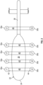
- the vehicle 20 includes a body or fuselage 22 having a generally aerodynamic shape and including a nose section 24, a trailing end or tail section 26 opposite from the nose section 24, and an airframe 28.
- the vehicle additionally includes at least one propulsion system 30 mounted to the fuselage 22.
- the vehicle 20 has a plurality of rotor propulsion systems 30 mounted at each opposing side of the fuselage; however, it should be understood that a vehicle 20 having any number of rotor propulsion systems 30 including a single rotor propulsion system, and/or a single rotor propulsion system mounted at each side of the fuselage is within the scope of the disclosure.
- the rotor propulsion systems 30 are mounted to the fuselage 22 in groups, for example pairs, with each pair including a first rotor propulsion 30a system arranged adjacent to a first side of the fuselage 22 and a second rotor propulsion system 30b arranged adjacent to a second, opposite side of the fuselage 22.
- the first and second rotor propulsion system 30a, 30b within a pair may be substantially identical such that the rotor propulsion systems 30a, 30b are capable of balancing forces therebetween.
- each of the rotor propulsion systems mounted at the same side of the aircraft may have similar, or alternatively, may have different configurations.
- the vehicle 20 may include at least one rotor propulsion system operable during a first flight mode, indicated at L1-L8, such as during take-off or landing for example, and at least one rotor propulsion system, identified at C1-C2, operable during a second mode of operation, such as during cruise for example.
- the size and/or configuration of at least a portion of a rotor propulsion system 30a, 30b associated with the first flight mode may be different than the size and/or configuration of at least a portion of a rotor propulsion system 30a, 30b associated with the second flight mode.
- Each rotor propulsion system 30 is mounted to a portion of the fuselage 22, such as to the airframe 28 for example, via a structural component or strut 40.
- a pair of rotor propulsion systems 30a, 30b may be mounted to the fuselage 22 via a single strut 40.
- the first rotor propulsion system 30a may be mounted at a first end 42 of the strut 40 and the second rotor propulsion system 30b may be mounted at the second end 44 of the strut 40.
- each rotor propulsion system 30 is mounted to a separate strut 40 are also contemplated herein.
- each rotor propulsion system 30 includes a rotor 46 having a plurality of rotor blades 48 mounted to a rotor hub 50.
- a rotor shaft 52 extending from the rotor hub 50 may be driven about an axis of rotation X via an electric component, such as an electric motor, illustrated schematically at 54.
- Each rotor 46 may be driven by a separate motor 54, or alternatively, a plurality of rotors 46 may be driven by a single motor 54.
- the one or more electric motors 54 may be controlled by a controller CONT in response to a flight control system (not shown).
- vehicle 20 is described herein as having rotor propulsion systems 30 that include an electric motor 54, it should be understood that embodiments where the vehicle 20 is a hybrid vehicle and therefore additionally includes a gas turbine engine operably coupled to the one or more rotors 46 are also within the scope of the disclosure. Further, it should be appreciated that other configurations of an aircraft including fixed-wing aircraft, tiltrotor aircraft, rotary-wing aircraft, and tail-sitting VTOL aircraft, and other vehicles having an electrically powered rotor propulsion system may also benefit from embodiments disclosed.
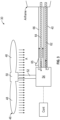
- cooling system 60 including a cooling fluid C is therefore used to remove heat from the electrical components to maintain the electrical components at a suitable temperature.
- the cooling system 60 associated with a motor 54 of a rotor propulsion system is at least partially embedded within the interior of the strut 40 supporting the motor 54 and the corresponding rotor 46 of the rotor propulsion system 30.
- at least one conduit fluidly connected to the motor 54 is arranged within the strut 40.
- the at least one conduit may include one or more conduits 62 configured to move the heated cooling fluid away from the motor 54 and/or one or more conduits 64 for delivering a cool temperature cooling fluid to the motor 54.
- Heat is configured to be removed from the cooling fluid while the cooling fluid C is arranged within the interior of the strut 40.
- the cooling fluid within the interior of the strut 40 is cooled via a heat exchange relationship with a secondary fluid.
- the secondary fluid may be another fluid provided from a source located onboard the vehicle 20, such as fuel for example, or may be provided from a source external to the vehicle 20.
- An airflow, such as the fresh or outside air A moved by the rotor 46 of the rotor propulsion system 30 and/or generated by movement of the vehicle 20 may be used as the secondary fluid to cool the cooling fluid.
- the secondary fluid is configured to flow about an exterior of the strut 40 to cool the cooling fluid C.
- the secondary fluid may be configured to flow through the interior of the strut 40.
- one or more scoops 65 formed at an exterior of the strut 40 may provide an inlet to the interior of the strut 40.
- a heat exchanger 66 is arranged within the interior of the strut 40 along the fluid flow path of the cooling fluid C. As shown in FIG. 3 , the heat exchanger 66 may be arranged directly upstream from the motor relative to flow of the cooling fluid C. In such embodiments, as a flow of heated cooling fluid moves through the conduit 64 towards the motor 54, heat is transferred to the secondary fluid. Accordingly, by the time that the cooling fluid C reaches the motor 54, the cooling fluid C has been cooled to a suitable temperature to remove heat from the motor 54. In other embodiments, best shown in FIG. 5 , the heat exchanger 66 may be arranged downstream from the electric motor 54 relative to the flow of the cooling fluid C such that the cooling fluid C is cooled generally directly downstream from the outlet of the motor 54.
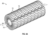
- FIGS. 4A and 4B An example of a heat exchanger 66 positionable within the interior of a strut 40 is illustrated in FIGS. 4A and 4B .
- the heat exchanger 66 is a tube-fin heat exchanger having a generally cylindrical base 68 configured to receive the heated cooling fluid C.
- the conduit containing the heated cooling fluid C may be mounted concentrically within the interior 70 of the base 68, or in an embodiment, the hollow interior of the base 68 may define a portion of the conduit.
- a plurality of fins 72 extends generally radially outwardly from the base 68.
- the fins 72 may extend over the entire length (between a first end and a second opposite end) of the base, or may extend over only a portion of the length thereof.
- Each of the plurality of fins 72 is spaced apart from another of the plurality of fins 72.
- the heat exchanger 66 is substantially axisymmetric about its longitudinal axis L.
- the plurality of fins 72 may, but need not be, substantially identical.
- the size and/or shape of each of the plurality of fins 72 may be generally constant over its length.
- the size and/or shape of at least one of the plurality of fins 72 may vary about the periphery of the base 68 or over the length of the base 68.
- one or more of the plurality of fins 72 has a constant thickness, but a non-linear contour.
- all or at least a portion of the fins 72 has one or more waves extending along the longitudinal axis L of the heat exchanger 66.
- heat exchanger illustrated and described herein is intended as an example only and that any suitable type of heat exchanger, such as a double pipe, shell and tube, plate, plate and shell, adiabatic shell, plate fin, pillow plate, and fluid heat exchanger is within the scope of the disclosure.
- the vehicle 20 may have a separate cooling system 60 associated with each of the plurality of rotor propulsion systems 30 and/or electrical components.
- a single cooling system 60 may be operably coupled to a plurality of rotor propulsion systems 30.
- the cooling system 60 is a closed loop system configured to cool each of the rotor propulsion systems 30.
- the cooling system 60 includes a tank 80 containing a volume of cooling fluid C.
- a pump 82 is configured to deliver cooling fluid from the tank 80 to one or more delivery conduits 64.
- Each of the plurality of conduits 64 is fluidly connected to a main conduit 84 such that the cooling fluid C may be delivered to the conduits 64 in parallel.
- a valve may be arranged within the conduit 64 or at the interface between the main conduit 84 and a respective conduit 64.
- the valve may be operable to selectively control a flow of cooling fluid C to the motor 54 of the rotor propulsion system 30 associated with the conduit 64, such as based on an operational state of the motor 54 for example.
- the heated flow of cooling fluid C output from the motor 54 is then cooled within the strut 40 as it passes through the conduit 62 to a second main conduit 86 configured to return the cooling fluid C to the tank 80.
- cooling system 60 Other electrical components of the vehicle 20, such as a generator for example, may also be cooled by the cooling system 60.
- a first portion of the cooling fluid C output from the tank 80 may be directed towards a generator 88 while the second portion is provided to the main conduit 84 for delivery to the rotor propulsion systems 30.
- the cooling fluid output from the generator 88 may then be provided directly to the tank 80, or alternatively, may be cooled, such as via a heat exchanger for example, before being returned to the tank 80.
- cooling fluid C from the pump 82 can also be directed to one or more motor controllers to cool them (not shown).
- a vehicle having a cooling system 60 as described herein may have a reduced sizing envelope, weight, and energy consumption.
Landscapes
- Engineering & Computer Science (AREA)
- Mechanical Engineering (AREA)
- Aviation & Aerospace Engineering (AREA)
- Chemical & Material Sciences (AREA)
- Combustion & Propulsion (AREA)
- Remote Sensing (AREA)
- Oil, Petroleum & Natural Gas (AREA)
- Electric Propulsion And Braking For Vehicles (AREA)
- Microelectronics & Electronic Packaging (AREA)
- Physics & Mathematics (AREA)
- Thermal Sciences (AREA)
Applications Claiming Priority (1)
| Application Number | Priority Date | Filing Date | Title |
|---|---|---|---|
| US17/406,616 US12275534B2 (en) | 2021-08-19 | 2021-08-19 | Motor cooling system |
Publications (2)
| Publication Number | Publication Date |
|---|---|
| EP4137414A1 true EP4137414A1 (de) | 2023-02-22 |
| EP4137414B1 EP4137414B1 (de) | 2024-12-18 |
Family
ID=83319113
Family Applications (1)
| Application Number | Title | Priority Date | Filing Date |
|---|---|---|---|
| EP22188799.5A Active EP4137414B1 (de) | 2021-08-19 | 2022-08-04 | Motorkühlsystem |
Country Status (2)
| Country | Link |
|---|---|
| US (1) | US12275534B2 (de) |
| EP (1) | EP4137414B1 (de) |
Cited By (1)
| Publication number | Priority date | Publication date | Assignee | Title |
|---|---|---|---|---|
| US20210039775A1 (en) * | 2015-05-19 | 2021-02-11 | Aeronext Inc. | Rotary-wing aircraft |
Families Citing this family (1)
| Publication number | Priority date | Publication date | Assignee | Title |
|---|---|---|---|---|
| CN218258678U (zh) * | 2022-07-25 | 2023-01-10 | 深圳市道通智能航空技术股份有限公司 | 一种机臂及无人机 |
Citations (5)
| Publication number | Priority date | Publication date | Assignee | Title |
|---|---|---|---|---|
| WO2016192022A1 (en) * | 2015-06-01 | 2016-12-08 | SZ DJI Technology Co., Ltd. | System, kit, and method for dissipating heat generated by a motor assembly |
| CN107458604A (zh) * | 2017-08-24 | 2017-12-12 | 泸州深远世宁无人机科技有限公司 | 一种具有防寒功能的遥控飞机 |
| CN207111223U (zh) * | 2017-09-08 | 2018-03-16 | 成都军融项目管理有限公司 | 一种无人机发动机的冷却系统 |
| WO2020043300A1 (de) * | 2018-08-30 | 2020-03-05 | Viafly Gmbh | Drohne mit rotorenkühlung durch zwangsluft |
| JP2020131781A (ja) * | 2019-02-14 | 2020-08-31 | ウシオ電機株式会社 | 飛行体 |
Family Cites Families (4)
| Publication number | Priority date | Publication date | Assignee | Title |
|---|---|---|---|---|
| FR2734319B1 (fr) | 1995-05-15 | 1997-07-18 | Aerospatiale | Dispositif pour prelever et refroidir de l'air chaud au niveau d'un moteur d'aeronef |
| FR2987602B1 (fr) | 2012-03-02 | 2014-02-28 | Aircelle Sa | Nacelle de turbomoteur equipe d'un echangeur de chaleur |
| US11130582B2 (en) | 2018-08-03 | 2021-09-28 | Rolls-Royce Corporation | Systems and methods of optimizing cooling and providing useful heating from single phase and two phase heat management in propulsion systems |
| FR3105173B1 (fr) * | 2019-12-20 | 2022-01-07 | Univ De Technologie De Compiegne Utc | Drone hydraulique multi-rotor |
-
2021
- 2021-08-19 US US17/406,616 patent/US12275534B2/en active Active
-
2022
- 2022-08-04 EP EP22188799.5A patent/EP4137414B1/de active Active
Patent Citations (5)
| Publication number | Priority date | Publication date | Assignee | Title |
|---|---|---|---|---|
| WO2016192022A1 (en) * | 2015-06-01 | 2016-12-08 | SZ DJI Technology Co., Ltd. | System, kit, and method for dissipating heat generated by a motor assembly |
| CN107458604A (zh) * | 2017-08-24 | 2017-12-12 | 泸州深远世宁无人机科技有限公司 | 一种具有防寒功能的遥控飞机 |
| CN207111223U (zh) * | 2017-09-08 | 2018-03-16 | 成都军融项目管理有限公司 | 一种无人机发动机的冷却系统 |
| WO2020043300A1 (de) * | 2018-08-30 | 2020-03-05 | Viafly Gmbh | Drohne mit rotorenkühlung durch zwangsluft |
| JP2020131781A (ja) * | 2019-02-14 | 2020-08-31 | ウシオ電機株式会社 | 飛行体 |
Cited By (2)
| Publication number | Priority date | Publication date | Assignee | Title |
|---|---|---|---|---|
| US20210039775A1 (en) * | 2015-05-19 | 2021-02-11 | Aeronext Inc. | Rotary-wing aircraft |
| US11772782B2 (en) * | 2015-05-19 | 2023-10-03 | Aeronext Inc. | Rotary-wing aircraft |
Also Published As
| Publication number | Publication date |
|---|---|
| US12275534B2 (en) | 2025-04-15 |
| US20230055244A1 (en) | 2023-02-23 |
| EP4137414B1 (de) | 2024-12-18 |
Similar Documents
| Publication | Publication Date | Title |
|---|---|---|
| CN108974348B (zh) | 使用电分布式反扭矩发电机和反向电动马达推力来使主旋翼减速的旋翼制动效果 | |
| CN111232223B (zh) | 推进发动机热管理系统 | |
| CN102695862B (zh) | 涡轮发动机推进单元的流体冷却装置 | |
| WO2021064382A2 (en) | Systems and methods for aircraft | |
| EP4137414B1 (de) | Motorkühlsystem | |
| EP4663548A1 (de) | Flugzeugantriebssystem mit intermittierendem verbrennungsmotor und elektrischem übertragungssystem und verfahren zum betrieb davon | |
| EP3733518B1 (de) | Reverse-bootstrap-luftzyklusmaschine | |
| WO2021231699A1 (en) | Ice protection for electrically powered rotors | |
| EP4650270A1 (de) | Unterflügelwärmetauscheranordnung für ein flugzeug | |
| US11725882B2 (en) | Cooling system for rotor hub mounted component | |
| CN115195988A (zh) | 一种新型垂直起降固定翼无人机气动布局 | |
| US12043400B2 (en) | Cooling system for aircraft components including ram chute body and relatively rotatable air conduit | |
| EP4561898B1 (de) | Systeme und verfahren zur bewältigung von eisablagerungen während des fluges von flugzeugen | |
| EP4382427B1 (de) | Klimaregelungssystem mit mischflussturbine | |
| US20260028127A1 (en) | Bleed air powered ambient aircraft environmental control system | |
| EP4428002A1 (de) | Hyperloop-klimaanlagensteuerungssystem | |
| EP4342798A1 (de) | Niederdruckluftkreislauf | |
| US20240418122A1 (en) | Aircraft air system with dedicated compressor(s) | |
| CN121263360A (zh) | 用于机载燃料电池系统的热管理空气涵道 | |
| WO2026049797A1 (en) | Systems and methods for managing ice accretions during flight of aircraft |
Legal Events
| Date | Code | Title | Description |
|---|---|---|---|
| PUAI | Public reference made under article 153(3) epc to a published international application that has entered the european phase |
Free format text: ORIGINAL CODE: 0009012 |
|
| STAA | Information on the status of an ep patent application or granted ep patent |
Free format text: STATUS: THE APPLICATION HAS BEEN PUBLISHED |
|
| AK | Designated contracting states |
Kind code of ref document: A1 Designated state(s): AL AT BE BG CH CY CZ DE DK EE ES FI FR GB GR HR HU IE IS IT LI LT LU LV MC MK MT NL NO PL PT RO RS SE SI SK SM TR |
|
| STAA | Information on the status of an ep patent application or granted ep patent |
Free format text: STATUS: REQUEST FOR EXAMINATION WAS MADE |
|
| 17P | Request for examination filed |
Effective date: 20230817 |
|
| RBV | Designated contracting states (corrected) |
Designated state(s): AL AT BE BG CH CY CZ DE DK EE ES FI FR GB GR HR HU IE IS IT LI LT LU LV MC MK MT NL NO PL PT RO RS SE SI SK SM TR |
|
| GRAP | Despatch of communication of intention to grant a patent |
Free format text: ORIGINAL CODE: EPIDOSNIGR1 |
|
| STAA | Information on the status of an ep patent application or granted ep patent |
Free format text: STATUS: GRANT OF PATENT IS INTENDED |
|
| INTG | Intention to grant announced |
Effective date: 20240718 |
|
| GRAS | Grant fee paid |
Free format text: ORIGINAL CODE: EPIDOSNIGR3 |
|
| GRAA | (expected) grant |
Free format text: ORIGINAL CODE: 0009210 |
|
| STAA | Information on the status of an ep patent application or granted ep patent |
Free format text: STATUS: THE PATENT HAS BEEN GRANTED |
|
| AK | Designated contracting states |
Kind code of ref document: B1 Designated state(s): AL AT BE BG CH CY CZ DE DK EE ES FI FR GB GR HR HU IE IS IT LI LT LU LV MC MK MT NL NO PL PT RO RS SE SI SK SM TR |
|
| REG | Reference to a national code |
Ref country code: CH Ref legal event code: EP |
|
| REG | Reference to a national code |
Ref country code: DE Ref legal event code: R096 Ref document number: 602022008784 Country of ref document: DE |
|
| REG | Reference to a national code |
Ref country code: IE Ref legal event code: FG4D |
|
| REG | Reference to a national code |
Ref country code: LT Ref legal event code: MG9D |
|
| PG25 | Lapsed in a contracting state [announced via postgrant information from national office to epo] |
Ref country code: HR Free format text: LAPSE BECAUSE OF FAILURE TO SUBMIT A TRANSLATION OF THE DESCRIPTION OR TO PAY THE FEE WITHIN THE PRESCRIBED TIME-LIMIT Effective date: 20241218 |
|
| PG25 | Lapsed in a contracting state [announced via postgrant information from national office to epo] |
Ref country code: FI Free format text: LAPSE BECAUSE OF FAILURE TO SUBMIT A TRANSLATION OF THE DESCRIPTION OR TO PAY THE FEE WITHIN THE PRESCRIBED TIME-LIMIT Effective date: 20241218 |
|
| PG25 | Lapsed in a contracting state [announced via postgrant information from national office to epo] |
Ref country code: BG Free format text: LAPSE BECAUSE OF FAILURE TO SUBMIT A TRANSLATION OF THE DESCRIPTION OR TO PAY THE FEE WITHIN THE PRESCRIBED TIME-LIMIT Effective date: 20241218 |
|
| PG25 | Lapsed in a contracting state [announced via postgrant information from national office to epo] |
Ref country code: NO Free format text: LAPSE BECAUSE OF FAILURE TO SUBMIT A TRANSLATION OF THE DESCRIPTION OR TO PAY THE FEE WITHIN THE PRESCRIBED TIME-LIMIT Effective date: 20250318 |
|
| REG | Reference to a national code |
Ref country code: NL Ref legal event code: MP Effective date: 20241218 |
|
| PG25 | Lapsed in a contracting state [announced via postgrant information from national office to epo] |
Ref country code: GR Free format text: LAPSE BECAUSE OF FAILURE TO SUBMIT A TRANSLATION OF THE DESCRIPTION OR TO PAY THE FEE WITHIN THE PRESCRIBED TIME-LIMIT Effective date: 20250319 Ref country code: LV Free format text: LAPSE BECAUSE OF FAILURE TO SUBMIT A TRANSLATION OF THE DESCRIPTION OR TO PAY THE FEE WITHIN THE PRESCRIBED TIME-LIMIT Effective date: 20241218 |
|
| PG25 | Lapsed in a contracting state [announced via postgrant information from national office to epo] |
Ref country code: RS Free format text: LAPSE BECAUSE OF FAILURE TO SUBMIT A TRANSLATION OF THE DESCRIPTION OR TO PAY THE FEE WITHIN THE PRESCRIBED TIME-LIMIT Effective date: 20250318 |
|
| PG25 | Lapsed in a contracting state [announced via postgrant information from national office to epo] |
Ref country code: NL Free format text: LAPSE BECAUSE OF FAILURE TO SUBMIT A TRANSLATION OF THE DESCRIPTION OR TO PAY THE FEE WITHIN THE PRESCRIBED TIME-LIMIT Effective date: 20241218 |
|
| REG | Reference to a national code |
Ref country code: AT Ref legal event code: MK05 Ref document number: 1752087 Country of ref document: AT Kind code of ref document: T Effective date: 20241218 |
|
| PG25 | Lapsed in a contracting state [announced via postgrant information from national office to epo] |
Ref country code: SM Free format text: LAPSE BECAUSE OF FAILURE TO SUBMIT A TRANSLATION OF THE DESCRIPTION OR TO PAY THE FEE WITHIN THE PRESCRIBED TIME-LIMIT Effective date: 20241218 |
|
| PG25 | Lapsed in a contracting state [announced via postgrant information from national office to epo] |
Ref country code: PL Free format text: LAPSE BECAUSE OF FAILURE TO SUBMIT A TRANSLATION OF THE DESCRIPTION OR TO PAY THE FEE WITHIN THE PRESCRIBED TIME-LIMIT Effective date: 20241218 |
|
| PG25 | Lapsed in a contracting state [announced via postgrant information from national office to epo] |
Ref country code: ES Free format text: LAPSE BECAUSE OF FAILURE TO SUBMIT A TRANSLATION OF THE DESCRIPTION OR TO PAY THE FEE WITHIN THE PRESCRIBED TIME-LIMIT Effective date: 20241218 |
|
| PG25 | Lapsed in a contracting state [announced via postgrant information from national office to epo] |
Ref country code: IS Free format text: LAPSE BECAUSE OF FAILURE TO SUBMIT A TRANSLATION OF THE DESCRIPTION OR TO PAY THE FEE WITHIN THE PRESCRIBED TIME-LIMIT Effective date: 20250418 |
|
| PG25 | Lapsed in a contracting state [announced via postgrant information from national office to epo] |
Ref country code: PT Free format text: LAPSE BECAUSE OF FAILURE TO SUBMIT A TRANSLATION OF THE DESCRIPTION OR TO PAY THE FEE WITHIN THE PRESCRIBED TIME-LIMIT Effective date: 20250421 |
|
| PG25 | Lapsed in a contracting state [announced via postgrant information from national office to epo] |
Ref country code: EE Free format text: LAPSE BECAUSE OF FAILURE TO SUBMIT A TRANSLATION OF THE DESCRIPTION OR TO PAY THE FEE WITHIN THE PRESCRIBED TIME-LIMIT Effective date: 20241218 |
|
| PG25 | Lapsed in a contracting state [announced via postgrant information from national office to epo] |
Ref country code: AT Free format text: LAPSE BECAUSE OF FAILURE TO SUBMIT A TRANSLATION OF THE DESCRIPTION OR TO PAY THE FEE WITHIN THE PRESCRIBED TIME-LIMIT Effective date: 20241218 Ref country code: RO Free format text: LAPSE BECAUSE OF FAILURE TO SUBMIT A TRANSLATION OF THE DESCRIPTION OR TO PAY THE FEE WITHIN THE PRESCRIBED TIME-LIMIT Effective date: 20241218 |
|
| PG25 | Lapsed in a contracting state [announced via postgrant information from national office to epo] |
Ref country code: SK Free format text: LAPSE BECAUSE OF FAILURE TO SUBMIT A TRANSLATION OF THE DESCRIPTION OR TO PAY THE FEE WITHIN THE PRESCRIBED TIME-LIMIT Effective date: 20241218 |
|
| PG25 | Lapsed in a contracting state [announced via postgrant information from national office to epo] |
Ref country code: CZ Free format text: LAPSE BECAUSE OF FAILURE TO SUBMIT A TRANSLATION OF THE DESCRIPTION OR TO PAY THE FEE WITHIN THE PRESCRIBED TIME-LIMIT Effective date: 20241218 |
|
| PG25 | Lapsed in a contracting state [announced via postgrant information from national office to epo] |
Ref country code: IT Free format text: LAPSE BECAUSE OF FAILURE TO SUBMIT A TRANSLATION OF THE DESCRIPTION OR TO PAY THE FEE WITHIN THE PRESCRIBED TIME-LIMIT Effective date: 20241218 |
|
| PG25 | Lapsed in a contracting state [announced via postgrant information from national office to epo] |
Ref country code: SE Free format text: LAPSE BECAUSE OF FAILURE TO SUBMIT A TRANSLATION OF THE DESCRIPTION OR TO PAY THE FEE WITHIN THE PRESCRIBED TIME-LIMIT Effective date: 20241218 |
|
| REG | Reference to a national code |
Ref country code: DE Ref legal event code: R097 Ref document number: 602022008784 Country of ref document: DE |
|
| PG25 | Lapsed in a contracting state [announced via postgrant information from national office to epo] |
Ref country code: DK Free format text: LAPSE BECAUSE OF FAILURE TO SUBMIT A TRANSLATION OF THE DESCRIPTION OR TO PAY THE FEE WITHIN THE PRESCRIBED TIME-LIMIT Effective date: 20241218 |
|
| PGFP | Annual fee paid to national office [announced via postgrant information from national office to epo] |
Ref country code: DE Payment date: 20250724 Year of fee payment: 4 |
|
| PGFP | Annual fee paid to national office [announced via postgrant information from national office to epo] |
Ref country code: FR Payment date: 20250725 Year of fee payment: 4 |
|
| PLBE | No opposition filed within time limit |
Free format text: ORIGINAL CODE: 0009261 |
|
| STAA | Information on the status of an ep patent application or granted ep patent |
Free format text: STATUS: NO OPPOSITION FILED WITHIN TIME LIMIT |
|
| REG | Reference to a national code |
Ref country code: CH Ref legal event code: L10 Free format text: ST27 STATUS EVENT CODE: U-0-0-L10-L00 (AS PROVIDED BY THE NATIONAL OFFICE) Effective date: 20251029 |
|
| 26N | No opposition filed |
Effective date: 20250919 |
|
| REG | Reference to a national code |
Ref country code: CH Ref legal event code: H13 Free format text: ST27 STATUS EVENT CODE: U-0-0-H10-H13 (AS PROVIDED BY THE NATIONAL OFFICE) Effective date: 20260324 |
|
| PG25 | Lapsed in a contracting state [announced via postgrant information from national office to epo] |
Ref country code: MC Free format text: LAPSE BECAUSE OF FAILURE TO SUBMIT A TRANSLATION OF THE DESCRIPTION OR TO PAY THE FEE WITHIN THE PRESCRIBED TIME-LIMIT Effective date: 20241218 |
|
| PG25 | Lapsed in a contracting state [announced via postgrant information from national office to epo] |
Ref country code: LU Free format text: LAPSE BECAUSE OF NON-PAYMENT OF DUE FEES Effective date: 20250804 |
|
| PG25 | Lapsed in a contracting state [announced via postgrant information from national office to epo] |
Ref country code: CH Free format text: LAPSE BECAUSE OF NON-PAYMENT OF DUE FEES Effective date: 20250831 |