EP4137431A1 - Unité de capteur à bouton sensitif et procédé de déclenchement du bouton sensitif - Google Patents
Unité de capteur à bouton sensitif et procédé de déclenchement du bouton sensitif Download PDFInfo
- Publication number
- EP4137431A1 EP4137431A1 EP20930880.8A EP20930880A EP4137431A1 EP 4137431 A1 EP4137431 A1 EP 4137431A1 EP 20930880 A EP20930880 A EP 20930880A EP 4137431 A1 EP4137431 A1 EP 4137431A1
- Authority
- EP
- European Patent Office
- Prior art keywords
- hover
- electrode
- capacitance
- button
- trigger
- Prior art date
- Legal status (The legal status is an assumption and is not a legal conclusion. Google has not performed a legal analysis and makes no representation as to the accuracy of the status listed.)
- Withdrawn
Links
Images






Classifications
-
- H—ELECTRICITY
- H03—ELECTRONIC CIRCUITRY
- H03K—PULSE TECHNIQUE
- H03K17/00—Electronic switching or gating, i.e. not by contact-making and –breaking
- H03K17/94—Electronic switching or gating, i.e. not by contact-making and –breaking characterised by the way in which the control signals are generated
- H03K17/96—Touch switches
- H03K17/962—Capacitive touch switches
-
- B—PERFORMING OPERATIONS; TRANSPORTING
- B66—HOISTING; LIFTING; HAULING
- B66B—ELEVATORS; ESCALATORS OR MOVING WALKWAYS
- B66B1/00—Control systems of elevators in general
- B66B1/34—Details, e.g. call counting devices, data transmission from car to control system, devices giving information to the control system
- B66B1/46—Adaptations of switches or switchgear
- B66B1/461—Adaptations of switches or switchgear characterised by their shape or profile
-
- G—PHYSICS
- G06—COMPUTING OR CALCULATING; COUNTING
- G06F—ELECTRIC DIGITAL DATA PROCESSING
- G06F3/00—Input arrangements for transferring data to be processed into a form capable of being handled by the computer; Output arrangements for transferring data from processing unit to output unit, e.g. interface arrangements
- G06F3/01—Input arrangements or combined input and output arrangements for interaction between user and computer
- G06F3/02—Input arrangements using manually operated switches, e.g. using keyboards or dials
-
- H—ELECTRICITY
- H03—ELECTRONIC CIRCUITRY
- H03K—PULSE TECHNIQUE
- H03K17/00—Electronic switching or gating, i.e. not by contact-making and –breaking
- H03K17/94—Electronic switching or gating, i.e. not by contact-making and –breaking characterised by the way in which the control signals are generated
- H03K17/945—Proximity switches
- H03K17/955—Proximity switches using a capacitive detector
-
- B—PERFORMING OPERATIONS; TRANSPORTING
- B66—HOISTING; LIFTING; HAULING
- B66B—ELEVATORS; ESCALATORS OR MOVING WALKWAYS
- B66B2201/00—Aspects of control systems of elevators
- B66B2201/40—Details of the change of control mode
- B66B2201/46—Switches or switchgear
- B66B2201/4607—Call registering systems
- B66B2201/4638—Wherein the call is registered without making physical contact with the elevator system
-
- H—ELECTRICITY
- H03—ELECTRONIC CIRCUITRY
- H03K—PULSE TECHNIQUE
- H03K17/00—Electronic switching or gating, i.e. not by contact-making and –breaking
- H03K17/94—Electronic switching or gating, i.e. not by contact-making and –breaking characterised by the way in which the control signals are generated
- H03K17/96—Touch switches
- H03K2017/9602—Touch switches characterised by the type or shape of the sensing electrodes
-
- H—ELECTRICITY
- H03—ELECTRONIC CIRCUITRY
- H03K—PULSE TECHNIQUE
- H03K2217/00—Indexing scheme related to electronic switching or gating, i.e. not by contact-making or -breaking covered by H03K17/00
- H03K2217/94—Indexing scheme related to electronic switching or gating, i.e. not by contact-making or -breaking covered by H03K17/00 characterised by the way in which the control signal is generated
- H03K2217/96—Touch switches
- H03K2217/9607—Capacitive touch switches
- H03K2217/960735—Capacitive touch switches characterised by circuit details
-
- H—ELECTRICITY
- H03—ELECTRONIC CIRCUITRY
- H03K—PULSE TECHNIQUE
- H03K2217/00—Indexing scheme related to electronic switching or gating, i.e. not by contact-making or -breaking covered by H03K17/00
- H03K2217/94—Indexing scheme related to electronic switching or gating, i.e. not by contact-making or -breaking covered by H03K17/00 characterised by the way in which the control signal is generated
- H03K2217/96—Touch switches
- H03K2217/9607—Capacitive touch switches
- H03K2217/960755—Constructional details of capacitive touch and proximity switches
- H03K2217/960765—Details of shielding arrangements
-
- H—ELECTRICITY
- H03—ELECTRONIC CIRCUITRY
- H03K—PULSE TECHNIQUE
- H03K2217/00—Indexing scheme related to electronic switching or gating, i.e. not by contact-making or -breaking covered by H03K17/00
- H03K2217/94—Indexing scheme related to electronic switching or gating, i.e. not by contact-making or -breaking covered by H03K17/00 characterised by the way in which the control signal is generated
- H03K2217/96—Touch switches
- H03K2217/9607—Capacitive touch switches
- H03K2217/960785—Capacitive touch switches with illumination
Definitions
- the present invention relates to buttons of public health, especially inductive buttons under consideration of hygienic sensitivity, such as faucets, flush buttons of toilets, waterproof buttons of water boilers, etc., especially the button design of elevators.
- Chinese patent 201480079328 discloses a technical solution for controlling an elevator by using gestures, in its specification, it mentions technologies like cameras to record gestures, including presetting gestures, its main technical composition is to record or even customize gestures first, the data of these gestures is recorded in the system to form a gesture library, and then after detecting a gesture command, it is compared with the gesture library to determine the meaning of the gesture, which is somewhat similar to the face recognition technology that has become popular;
- This technology requires many and expensive hardware devices, on the other hand, users' customization is also very difficult, due to the variety of human gestures and movements, this technology has considerable challenges in the two contradictions of accurately determining recognition and anti-interference, the absence of this product on the market also indirectly shows the difficulty of the technology.
- the application No. 201610551225.5 proposes capacitive proximity button with groove, the capacitive proximity button is arranged at the bottom of the groove, by threshold design, the user's finger must be inserted into the groove to trigger the proximity button, the application does not disclose the specific capacitance measurement method of the capacitive proximity button, the solution has the defect that the user's finger sticks into the groove and easily touches the inner wall of the groove, especially in an environment such as an elevator where the lights are relatively dim and people may be crowded, at the same time, it is unlikely that the user of gesture induction can guarantee that the fingers of their movements can be completely controlled without shaking, otherwise the significance of hygienic sensitivity will be lost; on the other hand, the patent cannot avoid the impact of environmental factors such as temperature and humidity on the set thresholds.
- US Patent US7498822 discloses a solution of capacitive induction of proximity of human finger, which also uses capacitive electrodes with a similar depressed design, the above problems also exist, if we try to avoid the above problems, according to our experiments, it is necessary to make the finger and the switch brim with a distance of more than 2cm as the design basis, in that way, the switch set to depressed electrodes needs to be designed with an inner diameter of at least 5cm, which makes the arrangement of many switch buttons of the elevator a challenge; in addition, the patent discloses a technical solution to measure the capacitance only by analog circuit, in addition, in order to eliminate mutual disturbances, the equipotential method and differential amplifiers etc.
- the structure of the depressed electrode arrangement will increase the complexity of the structure molding of the hover button, which leads to an increase in processing costs, and affect the aesthetics of the hover button and the cleaning and disinfection of the elevator in the future.
- the US patent US7498822 only adopts the method of measuring self-capacitance, while rejecting the measuring method of mutual capacitance does not take advantage of the strong anti-interference ability of mutual capacitance to improve the performance of the hover button, in addition, this patent does not have the sound and light feedback system necessary for the hover button, it can cause confusion and inconvenience for the operator to use the hover button.
- Capacitance-to-digital conversion circuits of existing mature technologies, such as DAI7142 and ADI7147, adopt the method of ⁇ - ⁇ modulation to charge and discharge the measured capacitance for many times and comparing it with the reference capacitance (see: US Patent Number: 5,134,401 ) the measured capacitance value is directly converted into a digital counterpart, the measurement sensitivity of capacitance can be improved to 1ff level, which can easily meet the requirements of the measurement system for capacitance measurement sensitivity at a safe distance, especially, these chips are designed with multiple channels, which makes the circuit design simple and convenient, thereby effectively reducing the cost and installation difficulty.
- the capacitance detection technology Compared with the camera, infra-red or radio-frequency and other technologies, the capacitance detection technology has the characteristics of simple circuit structure and low cost etc. in detecting the proximity of the human body, but at the same time, there also exist small change in capacitance with high requirements for detection resolution, and capacitance detection extremely susceptible to environmental influences.
- the self-capacitance formed by the capacitive electrodes and the mutual capacitance formed between the electrodes will be affected by the approaching fingers, effectively using these affects to detect the proximity of the fingers while considering the different characteristics of the self-capacitance measurement and the mutual capacitance measurement, synchronously excluding the influence of other parts of the body, misoperation and environment on the measurement of electrode capacitance are not very easy at present.
- the purpose of the present invention is to overcome the deficiencies of the prior art, to create a capacitance sensor that is particularly suitable for the characteristics of the hover button, and cooperating with the mature capacitance-to-digital conversion technology, it makes full use of the specialties of CDC circuit in immunity to stray distributed capacitance, uses the combined measurement method of self-capacitance and mutual capacitance, coupled with three-state acousto-optic feedback circuit, considers the characteristics of human fingers approaching and avoids various interferences, to accurately determine the approaching action of fingers to trigger buttons, which is not only suitable for supporting of elevators, but also suitable for the transformation of existing elevator buttons, and it is also suitable for button controls of other hygienic sensitivity, the overall cost is easily accepted by commercialization.
- the invention creates a capacitive sensor unit corresponding to one button, a hover button sensor unit, comprising: a power supply circuit, a capacitive sensor, a capacitance-to-digital conversion circuit, a control module, an acousto-optic feedback control circuit, and a communication circuit;
- the capacitive sensor consists of one or more groups of electrodes, each group of electrodes comprises at least one central electrode, at least one peripheral electrode arranged around the central electrode, the height of the central electrode protruding from the peripheral electrode is 1.0-8.9mm;
- the capacitance-to-digital conversion circuit comprises a capacitance excitation signal circuit, and the capacitance excitation signal circuit generates a high-frequency square wave excitation signal;
- the above-mentioned central electrode and peripheral electrode are all connected to the capacitance-to-digital conversion circuit to detect self-capacitance and mutual capacitance of the group of central electrode and peripheral electrode after inducting the approaching of human fingers;
- the capacitance-to-digital conversion circuit is connected with the control module, and the control module outputs trigger logic signal of the button according to the range of effective hover trigger area above the central electrode where the human finger points to and dwell time within this range.
- the control module can use MCU, with the continuous development of electronic technology, there have been chips that combine the capacitance-to-digital conversion circuit CDC and the control module MCU, such as the PSoC 4100S Plus series of CYPRESS, but its functional composition remains the same.
- the button triggering method of the present invention is detecting and calculating that the human finger enters the effective hover trigger area above a certain central electrode through the capacitive sensor, and providing pre-trigger response of the human finger entering the effective hover trigger area through the acousto-optic feedback control circuit;
- the trigger logic signal of the button pointed by the human finger is directly output, and at the same time, the acousto-optic feedback control circuit responds to the triggered state; otherwise, it continuously detects whether the human finger stays in the effective hover trigger area or not, if it is and stays exceeding the set hover time, output the trigger signal of the button pointed by the human finger and at the same time the acousto-optic feedback control circuit responds to the triggered state; if it is detected that the finger has left the effective hover trigger area within the set hover time, the non-trigger state is returned.
- the electrode arrangement of the present invention has the following advantages: first, the risk of fingers touching the side wall is fundamentally avoided; second, there is no need to consider the safety distance of the side wall, thereby effectively reducing the diameter of the hover button, the outer diameter of the entire button can be controlled below 3CM, which can easily meet the spatial layout requirements of multi-row buttons; third, the universal block design is convenient for mass production; fourth, because there is no need to insert fingers into the concave container, the surface of the hover button with convex-structure of multi-row can be uniformly decorated with flat decorative materials, such as glass, acrylic or other non-conductive materials, and the convex-structure itself can be realized with one or two layers of PCB boards at low cost.
- the present invention applies to the buttons inducting the control of finger approaching in occasions of hygienic sensitivity, the elevator buttons are mainly introduced in detail below, the technologies achieved through these introductions are also applicable to button controls in other hygienic-sensitivity.
- buttons there are three cases, one is the case of one button, two is the case of two up and down buttons, and three is the case of multiple buttons in the elevator car;
- a finger For elevator users, it is possible to use a finger to trigger a button from different angles of up, down, left, and right, in the application scenario of a contact button switch, parallel to the direction of the button, within a 360-degree range, human fingers should trigger the switch no matter from any direction angle contacting the button, while in the direction perpendicular to the button, finger contacting the button at any angle from 0 to 90 degrees should trigger the switch, likewise the hover button should also satisfy the requirements that the switch can be effectively triggered within the same directions and angular range with the contact button.
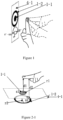
- Figure 1 shows three states of the human finger approaching the button electrode, including the parallel entry shown by the solid line, the 45° angle entry and the vertical 90° angle entry shown by the dotted lines
- in Figure 4-1 is the button panel
- 1-1 is the central electrode
- 1-2 is the peripheral electrode.
- the invention is to make the three kinds of approaching methods of fingers can be responded to.
- the hover button needs to effectively prevent false triggering caused by the large area of the human body approaching the hover button, including various false triggering situation such as when there are many people in the elevator, the arm or back is close to or appressed to the hover button, and when cleaning the palm or fist is close to the hover button.
- various false triggering situation such as when there are many people in the elevator, the arm or back is close to or appressed to the hover button, and when cleaning the palm or fist is close to the hover button.
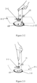
- Figure 2 shows a schematic diagram of three states of human fingers to trigger the button and a schematic diagram of the palm approaching the button
- the present invention requires that the method for triggering the hover button is: stretching out with the index finger, and making a fist with the remaining 4 fingers; this action is also normal pointing action of human fingers; as shown in Figure 1 , in the direction perpendicular to the hover button, it can approach the central electrode at any angle in the range of 0 to 90 degrees, and in the direction parallel to the hover button, it can approach the central electrode at any angle in the range of 360 degrees.
- Figures 2-1 , 2-2 and 2-3 show the cases where the finger approaches the hover button in the direction perpendicular to the hover button at angles of 0 degrees (horizontal), 45 degrees and 90 degrees, respectively, wherein the projected area s1 of finger to central electrode remains basically unchanged in the range of 0 to 90 degrees, while the projection s2 of finger to peripheral electrode remains basically unchanged in the range of 0 to 45 degrees, which is about 1/2 ⁇ r2 of the peripheral electrode area s21, wherein r2 is the radius of the peripheral electrode. Due to the influence of the remaining 4 fingers of the fist, the projected area s2 gradually increases in the range of 45 degrees to 90 degrees, and reaches a maximum value at an angle of 90 degrees, which is about 1/4 of the peripheral electrode area s21.
- the radius r1 of the central electrode is selected to be 1.25CM
- the inner ring radius of the peripheral electrode is 1.25CM
- the outer ring radius r2 is 1.75CM
- the height difference ⁇ d between the central electrode and the peripheral electrode of the convex electrode structure is 0.5CM
- the theoretical calculation values of C1/C2 when a finger with a diameter of about 1CM approaches the hover button from different angles and the palm approaches the hover button Proportion calculation table of C1/C2 (the length unit is cm, the area unit is cm 2 ) r1 r2 s1 s2 s1/s2 d1 ⁇ d d2 d1/d2 C 1/C2
- the present invention uses the analog switches in the capacitance-to-digital conversion circuit CDC to periodically time-sharing to detect the self-capacitance C1 formed by the central electrode 1-1 and the human body, and the self-capacitance C2 formed by the peripheral electrode 1-2 and the human body as well as the mutual capacitance C3 formed by the central electrode 1-1 and the peripheral electrode 1-2, one measurement period T is divided into three time segments T1, T2 and T3.
- the analog switches 3-3 and 3-5 are closed, and the analog switches 3-4 and 3-6 are shut off, at this time, the square wave excitation signal is applied to the central electrode 1-1, and the capacitance measurement signal is also taken out from the central electrode 1-1; in the T2 time period, the analog switches 3-3 and 3-5 are shut off, and the analog switches 3-4 and 3-6 are closed, at this time, the square wave excitation signal is applied to the peripheral electrode 1-2, and the capacitance measurement signal is also taken out from the central peripheral electrode 1-2; in the T3 time period, the analog switches 3-3 and 3-6 are closed, and the analog switches 3-4 and 3-5 are shut off.
- the square wave excitation signal is applied to the peripheral electrodes 1-2, and the capacitance measurement signal is taken out from the central electrode.
- the capacitance detection sensitivity can be increased to ff level to meet the requirements of the minimum safe distance, and on the other hand, it is not necessary to keep equipotential of the central electrode and the peripheral electrode to eliminate the influence of C3 as is proposed in patent No.: US 7,498,822 B2 , on the contrary, the time-sharing measurement of C3, which is not affected by C1 and C2, can make the hover button retain the function of contact quick triggering.
- the present invention uses the measurement of capacitance values of C1, C2 and C3 to set by calculation the effective hover trigger area 2-9 of the hover button in present invention represented by the dotted cylinder above the central electrode 1-1, when the finger enters the area and the hover time in the area exceeds the specified hover time threshold (for example, 1 second), the hover button is triggered.
- the specified hover time threshold for example, 1 second
- the distance dmin from the bottom surface of the effective hover trigger area to the central electrode 1-1 is set to 0.5CM, once the distance between the finger and the central electrode is less than 0.5CM, no hover time is required, and the hover button can be triggered immediately.
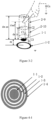
- the distance dmax from the top surface of the effective hover trigger area to the central electrode is set to 4CM, and the minimum safe distance dsaf from the finger to the hover button is set to 2CM, which can ensure that there is a vertical jitter interval of 2CM above the minimum safe distance, it can improve reliability of trigger, the radius r of the effective hover trigger area is approximately equal to the radius r1 of the central electrode. As shown in Figure 3-1 .
- formula (3) shows that the distance of the finger proximity has a one-to-one inverse relationship with the ratio C1/C2 of the two capacitances, that is, the distance d1 of the finger proximity can be calculated by using C1/C2, thus, as shown in Figure 3-2 , the largest height dmax, the minimum height dmin and the minimum safe distance dsaf of the effective hover trigger area 2-9 which approximates cylinder can all be set by the corresponding ratio of C1/C2, and the radius r of the effective hover trigger area 2-9 can use the capacitance value of the mutual capacitance C3 between the center electrode 1-1 and the peripheral electrode 1-2 to define it within a range approximately equal to the radius r1 of the central electrode 1-1. Note that there is no influence of the dielectric constant ⁇ in the formula (3), thus the influence of the temperature
- the effective hover trigger area above the central electrode is a cylinder whose cross-sectional shape is the projection of the periphery of the central electrode, and the bottom of which is the distance dmin away from the central electrode, dmax is the distance from its top to the central electrode, the above dmin is 0.5CM, the dmax is 4CM.
- the main consideration is that the mutual capacitance detection determination is very accurate, and it is less affected by the environment, and setting this value is for the consideration that determining whether the user wants to trigger quickly or not, while for the setting of dmax, it not only effectively balances the resolution and accuracy of the measurement, but also balances the problems caused by the necessary shaking of the user's finger during the hover trigger process.
- the finger when the finger searches for the effective hover trigger area of the target hover button, it may pass the effective hover trigger area of the adjacently arranged hover buttons, resulting in false trigger of adjacent hover buttons;
- the present invention adopts the method of specifying the hover time of the finger in the effective hover trigger area of the hover button, so as to avoid false trigger of passing the button.
- the hover time can be specified between 0.3s and 5s, in principle, the longer the hover time is, the better the anti-false trigger effect will be, however, if the hover time is too long, the trigger response time will be prolonged, and the user's operating experience will be affected, the elevator suspension button of the embodiment of present invention specifies that the suspension time is 0.5s-1s.
- the hover button needs to have a hover time (for example, 0.5s-1s), in order to meet the diverse needs of people, and the quick trigger requirements of the hover button in emergency situations, the hover button must retain the function of contact quick trigger, that is, when the finger touches the surface of the hover button, it can trigger the button switch immediately without waiting for the hover time to expire, see Figure 3-2 , when the human finger is closer to the central electrode than the above-mentioned effective hover trigger area range, that is, when the distance between the finger and the central electrode is less than dmin, it will enter the quick trigger area 2-10, at this time, there is no need to wait for the hover time to expire, and the hover button will be triggered immediately.
- a hover time for example, 0.5s-1s
- an anti-crosstalk electrode 1-4 is set, but the setting of the anti-crosstalk electrode 1-4 will bring about the problem that the measurement sensitivity of the central electrode 1-1 and the peripheral electrode 1-2 will decrease, in order to improve its measurement sensitivity, the active shielding electrodes 1-3 are arranged between the peripheral electrode 1-2 and the anti-crosstalk electrodes 1-4, and the active shielding electrodes 1-3 rely on the mature technology in the capacitance-to-digital conversion circuit CDC, that is, rely on the operational amplifier in the CDC to form a voltage follower connected with the central electrode or the peripheral electrode, to keep the active shielding electrode 1-3 between the central electrode 1-1 or the peripheral electrode 1-2 and the large-area metal ground or the earth electrode 1-4 at equipotential, thereby avoiding or reducing the loss of electric field energy of
- the contact button can usually provide the operator with tactual feedback of two states through the displacement action of the mechanical switch or the acousto-optic feedback circuit, that is, the trigger state and the non-trigger state, so that the operator can confirm that the button switch has been successfully triggered and can let the hand leave the button.
- the hover button of the present invention also includes an acousto-optic feedback control circuit 5-3 and a multi-color LED indicator 5-4, which is different from the tactual feedback of the two states of the above-mentioned contact button, in order to avoid false trigger caused by the finger passing the effective hover trigger area, the finger needs to hover in the effective hover trigger area for a specified time, and the hover button needs at least 3 states of non-contact tactual feedback (implemented by means of light or sound).
- the first state is the non-trigger state, which means that the finger has not entered the effective hover trigger area, it can be indicated by light off or silent;
- the second state is the pre-trigger state, which means that the finger has entered the effective trigger range, which can be indicated by a single-color light flashing or lighting up a specific color (eg: yellow) of the multi-color light, or using a certain sound, to remind the operator that it has entered the effective hover trigger area of the hover button;
- the third state is the triggered state, indicating that the finger has hovered for specified hover time in the effective trigger area, and the hover button is triggered, which can be indicated by the single-color indicator changing from flashing to steady lighting on or the multi-color indicator changing to another color, or using another sound.
- the central electrode 1-1, the peripheral electrodes 1-2 and the active shielding electrodes 1-3 and 1-7 are all connected to the CDC, and the CDC periodically time-sharing to measure the self-capacitance C1 formed between the central electrode 1-1 and the human body, the self-capacitance C2 formed between the peripheral electrodes and the human body and the mutual capacitance C3 formed between the central electrode 1-1 and the peripheral electrode 1-2, in order to improve the sensitivity of C1 or C2, the operational amplifier in the CDC is used to form the voltage follower, which makes the electrodes 1-3, 1-7 and 1-2 form an equipotential to achieve the effect of active shielding (refer to Figures 4-2 and 4-3 ).
- the CDC inputs the measured capacitance values of C1, C2 and C3 to the MCU, and the MCU calculates the value of C1/C2 and determines whether the finger enters or leaves the effective hover trigger area 2- 9 by calculation according to the values of C1/C2 and C3, according to the determination result, three-state acousto-optic feedback is provided through the acousto-optic feedback control circuit, and at the same time, the trigger logic signal of the hover button is sent to the elevator central controller through the communication circuit.
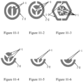
- the central electrode is preferably circular, and the outer electrode is preferably circular, of course, polygons can also be used, the central electrodes can be arranged with multiple electrodes, the mutual capacitance between the multiple electrodes further improves the reliability of the quick trigger area, and the peripheral electrodes can also be arranged with multiple electrodes, which is beneficial to more accurately determine the radius of the effective trigger area that is approximately a cylinder.
- Figures 11-1, 11-2 and 11-3, Figures 11-4, 11-5, and 11-6 respectively show the schematic diagrams of the arrangement form of 2 pieces of central electrodes, the arrangement form of 3 pieces of central electrodes, and the arrangement form of 6 pieces of central electrodes and 2 pieces of peripheral electrodes, 3 pieces of central electrodes and 1 pieces of peripheral electrodes in non-closed loop, 2 pieces of central electrodes and peripheral electrodes in non-closed loop, 1 piece of central electrodes and peripheral electrodes in non-closed loop.
- the central electrode may be composed of multiple petals
- the peripheral electrode may be composed of a closed-loop or open-loop of circular ring, or a semi-circular ring.
- the anti-crosstalk grounded annular electrode 1-4 and the active shielding electrode 1-3 can also be arranged on the same level as the central electrode, as shown in Figure 4-3 .
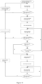
- the hover button operation method of the present invention is shown in Figure 12 , when the hover button is powered on, it first outputs a non-trigger logic signal, and then enters the non-trigger periodic cycle-detection and calculation stage, in this stage, it determines whether the finger has entered the effective hover trigger area or not, if not, the acousto-optic feedback control circuit outputs a non-trigger state, and continuing to perform detection and calculation in cycle, until it detects and calculates that the finger has entered the effective hover trigger area, the acousto-optic feedback control circuit outputs a pre-trigger state, at the same time, the hover timer starts timing, and the pre-trigger cycle-detection and calculation stage has be entered.
- the acousto-optic feedback control circuit In the pre-trigger cycle-detection and calculation stage, if the finger leaves the effective hover trigger area, the hover timer is cleared, the acousto-optic feedback control circuit outputs a non-trigger state, and it returns to the non-trigger cycle-detection and calculation stage; When the finger further enters the quick trigger area or the hover timer exceeds the pre-determined hover time, the acousto-optic feedback control circuit outputs the trigger state, at the same time, the logic trigger signal is output, and the post-trigger cycle-detection and calculation stage has been entered.
- the non-trigger state signal is output, the hover timer is cleared, at the same time, the sound and light feedback non-trigger state, and the non-trigger cycle-detection and calculation stage is returned.
- the hover button operation method of the present invention can meet the requirements of the following three operation modes: the first is a single-shot trigger mode, that is, the finger can leave the effective hover trigger area immediately after triggering, and does not need to be triggered again (applicable to elevators, various door switches, toilet flush switches etc.); The second is the continuous trigger mode, that is, the finger can leave the effective hover trigger area immediately after triggering, meanwhile it continues to output the trigger logic signal, until the finger triggers the hover switch for the second time, the non-trigger signal will be output (applicable to bath or wash basin faucet switch, various lighting lamp on and off control); The third is the hover-maintaining trigger mode, that is, the finger remains in the effective hover trigger area after triggering, and the trigger logic signal is continuously output during the period, until the finger leaves the effective hover trigger area, the non-trigger logic signal is output (applicable to public water drinking control buttons in offices, high-speed railways, airports, stations etc.).
- Figure 7 shows a most reasonable embodiment, which can also be conveniently applied to other similar fields, such as the design of the trigger button of the faucet;
- Figure 8 shows an embodiment of a reasonable arrangement;
- the optimal design is to bring a row of buttons together into a set, and each set of a row of buttons is connected to another set by a serial interface like building blocks, and then connected to a master controller.
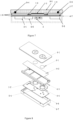
- An embodiment of the hover button of the present invention is an independent hover button, as shown in the structure diagram of the independent hover button in Figure 7 and the circuit principle block diagram in Figure 9 , it is made of multiple layers of circuit boards 1-6, the central electrodes 1-1 are made on the top layer of the circuit board, the peripheral electrodes 1-2 are made on the second layer of the circuit board, the active shielding electrodes 1-7 are made on the third layer of the circuit board, and the power supply circuit 5-1, the communication circuit 5-2, CDC circuit 3 and the acousto-optic feedback control circuit 5-3 are arranged on the fourth layer of the circuit board.
- the panel 4-1 is made of acrylic or transparent PC
- the top layer is screen-printed with luminous ink for the button shape
- other positions on the top layer are screen-printed with opaque ink to ensure it will display the status of button when the LED light-emitting element 5- 4 is lit.
- the rear side of the panel 4-1 and the top layer of the multi-layer circuit board of the button are connected by bonding, and the metal casing 4-7 can also connect the multi-layer circuit board and the panel by bonding.
- Multi-color LED light-emitting element 5-4 is arranged on the top layer of the multi-layer circuit board 1-6 and the acousto-optic feedback control circuit 5-3 is arranged on the bottom layer of the multi-layer circuit board to implement the aforementioned three-state light feedback (that is, when the finger does not enter the effective hover trigger space, the green light is on, when the finger enters the effective hover trigger space, the purple light is on, and after the hover button is triggered, the red light is on), the central electrode 1-1 is arranged on the top layer of the multi-layer circuit board, the peripheral electrodes 1-2 is arranged on the second layer and the active shielding electrodes 1-7 is arranged on the third layer, so as to avoid the problem that the metal casing ground 4-7 and the bottom control circuit layer reduce the sensitivity at the same time.
- Power supply circuit 5-1, CDC circuit 3 and communication circuit 5-2 are arranged on the fourth layer of the circuit board, to implement the elevator's outbound call control and light indication functions by communicating with the elevator's control and signal system through the serial communication interface.
- the hover independent button of convex structure of present invention is simple in structure and low in cost, which can be conveniently used to replace the existing mechanical contact independent button switch.
- FIG. 8 Another embodiment of the hover button of the present invention is double hover buttons used for elevator outbound calls, as shown in the structural diagram 8 and the principle block diagram 9, the central electrodes 1-1 of the two hover buttons are screen-printed with silver paste on the transparent panel 4-1, and under the transparent panel 4-1, a uniform light plate 4-2 for making the beams of light feedback uniform is arranged, the transparent panel and the uniform light plate are fixed with the peripheral electrode PCB board 4-4 by frame 4-3, the vertical distance difference ⁇ d between the central electrode and the peripheral electrode of the convex electrode structure is controlled to be 0.5CM through the frame, and a control PCB board 4-6 is arranged under the electrode PCB board 4-4, as shown in the equivalent circuit diagram of Figure 9 , there is the CDC special chip integrating CDC and MCU on the control PCB board 4-6, which is used to measure the capacitance values C1, C2 and C3 of the hover button, and implement the functions of the hover button by calculating the ratio of C1/C2 and comparing the size of C3.
- Multi-color LED indicator 5-4 and acousto-optic feedback control circuit 5-3 are also arranged on the control PCB board 4-6, which are used to implement the aforementioned three-state light feedback (that is, when the finger does not enter the effective hover trigger space, the green light is on, when the finger enters the effective hover trigger space, the purple light is on, and after the hover button is triggered, the red light is on), the peripheral electrode 1-2, annular active shielding electrodes 1-3 and annular grounded electrode 1-4 are arranged on top of the PCB board 4-4, the active shielding electrodes 1-7 are arranged under the PCB board 4-4, and the active shielding electrodes are connected to the annular active shielding electrodes on the electrode PCB board 4-4 through the PCB vias 1-8, so as to avoid the problem that the metal casing ground and the external annular grounded electrode reduce the sensitivity at the same time.
- the power supply circuit 5-1, the CDC circuit 3 and the communication feedback circuit 5-2 are also arranged on the control PCB board 4-6, to
- hover button of the present invention is multi-row hover button used for floor selection control in the elevator car, as shown in the structural diagram 10 and the principle block diagram 9, a plurality of double buttons basic control units 4 and one centralized controller 6 are arranged on metal frame and connected in series through 6-1 independent unit communication lines to connect to the centralized controller 6.
- FIG 8 of the structural reference diagram of the double buttons basic control unit 4 the central electrodes 1-1 of the double hover buttons are screen-printed on the transparent panel 4-1 with silver paste, the uniform light plate 4-2 for making the beams of light feedback uniform is arranged under the transparent panel 4-1, and the transparent panel and the uniform light plate are fixed with the electrode PCB board 4-4 through the frame 4-3, the vertical distance difference ⁇ d between the central electrode and the peripheral electrode of the convex electrode structure is controlled to be 0.5CM through the frame, the control PCB board 4-6 is arranged under the electrode PCB board 4-4, as shown in the equivalent circuit diagram of Figure 9 , there is the CDC special chip integrating CDC and MCU on the control PCB board 4-6, which is used to measure the capacitance values C1, C2 and C3 of the hover button, and implement the functions of the hover button by calculating the ratio of C1/C2 and comparing the size of C3.
- the multi-color LED indicator 5-4 and the acousto-optic feedback control circuit 5-3 are also arranged on the control PCB board 4-6, which are used to implement the aforementioned three-state light feedback (that is, when the finger does not enter the effective hover trigger space, the green light is on, when the finger enters the effective hover trigger space, the purple light is on, and after the hover button is triggered, the red light is on), the peripheral electrode 1-2, annular active shielding electrodes 1-3 and annular grounded electrode 1-4 are arranged on top of the PCB board 4-4, the active shielding electrodes 1-7 are arranged under the PCB board 4-4, and the active shielding electrodes are connected with the annular active shielding electrodes on the electrode PCB board 4-4 through the PCB vias 1-8, so as to avoid the problem that the metal casing ground and the external annular grounded electrode reduce the sensitivity at the same time.
- the power supply circuit 5-1, the CDC circuit 3 and the communication feedback circuit 5-2 are also arranged on the control PCB board 4-6, the control PCB board 4-6 is connected to the centralized control PCB board 6 through internal serial communication cable 6-1, on the centralized controller 6, there is a MCU (reference No. 6-3) responsible for comprehensively analyzing the button actions of the basic unit 4 to further reduce misoperation, and the centralized power supply module 6-2 is responsible for supplying the power to the power supply circuit 5-1 of independent control unit 4, a centralized communication control module 6-4 is responsible for communicating with the central controller of the elevator, and at the same time communicating with each basic control unit 4, so as to implement the functions of floor control and light indication of the elevator.
- a MCU reference No. 6-3
- the present invention uses the ratio of the central capacitance to the external capacitance as the main determining basis, while the capacitance ratio has nothing to do with the dielectric constant mainly affected by temperature and humidity.
- the hover button of the present invention can effectively prevent false triggering caused by a large area of the human body approaching the hover button, for example, when there are many people in the elevator, the arm or back is close to or appressed to the hover button, and when cleaning the palm or fist is close to the hover button etc..
- the general length of the finger is significantly different from the entire palm on the effect to the two electrodes designed by the invention, therefore, considering that most people are accustomed to use the index finger to operate the button switch, while the length of the index finger for adults is about 6-8CM, for children is 4-6CM, in order to avoid the remaining 4 fingers from increasing the projected area of the index finger to the external electrode, the diameter (circular) or side length (foursquare) of the external electrode should be controlled within 4CM.
Landscapes
- Engineering & Computer Science (AREA)
- Automation & Control Theory (AREA)
- General Engineering & Computer Science (AREA)
- Theoretical Computer Science (AREA)
- Computer Networks & Wireless Communication (AREA)
- Human Computer Interaction (AREA)
- Physics & Mathematics (AREA)
- General Physics & Mathematics (AREA)
- Switches That Are Operated By Magnetic Or Electric Fields (AREA)
- User Interface Of Digital Computer (AREA)
Applications Claiming Priority (3)
| Application Number | Priority Date | Filing Date | Title |
|---|---|---|---|
| CN202010287562.4A CN111573457B (zh) | 2020-04-13 | 2020-04-13 | 一种悬停按钮传感器单元及提供悬停按钮触发的方法 |
| CN202020539977.1U CN212356103U (zh) | 2020-04-13 | 2020-04-13 | 一种悬停按钮传感器单元及悬停触发按钮 |
| PCT/CN2020/089182 WO2021208156A1 (fr) | 2020-04-13 | 2020-05-08 | Unité de capteur à bouton sensitif et procédé de déclenchement du bouton sensitif |
Publications (2)
| Publication Number | Publication Date |
|---|---|
| EP4137431A1 true EP4137431A1 (fr) | 2023-02-22 |
| EP4137431A4 EP4137431A4 (fr) | 2024-06-19 |
Family
ID=78083518
Family Applications (1)
| Application Number | Title | Priority Date | Filing Date |
|---|---|---|---|
| EP20930880.8A Withdrawn EP4137431A4 (fr) | 2020-04-13 | 2020-05-08 | Unité de capteur à bouton sensitif et procédé de déclenchement du bouton sensitif |
Country Status (4)
| Country | Link |
|---|---|
| US (1) | US20230198523A1 (fr) |
| EP (1) | EP4137431A4 (fr) |
| JP (1) | JP7401078B2 (fr) |
| WO (1) | WO2021208156A1 (fr) |
Families Citing this family (5)
| Publication number | Priority date | Publication date | Assignee | Title |
|---|---|---|---|---|
| EP4008659B1 (fr) * | 2020-12-03 | 2025-07-02 | Otis Elevator Company | Dispositifs d'entrée d'utilisateur |
| KR102896241B1 (ko) * | 2021-03-31 | 2025-12-08 | 삼성전자주식회사 | 무선 전력 수신, 무선 통신, 및 전기 자극을 수행하는 장치 및 방법 |
| WO2023151806A1 (fr) * | 2022-02-11 | 2023-08-17 | Kone Corporation | Bouton d'appel d'ascenseur et procédé de commande d'un bouton d'appel d'ascenseur |
| CN121569203A (zh) * | 2023-08-28 | 2026-02-24 | 阿尔卑斯阿尔派株式会社 | 静电电容型传感器、传感器片、传感器单元、检测电路以及静电电容检测装置 |
| JP7635868B1 (ja) | 2024-03-13 | 2025-02-26 | フジテック株式会社 | エレベータ |
Family Cites Families (16)
| Publication number | Priority date | Publication date | Assignee | Title |
|---|---|---|---|---|
| US4022296A (en) * | 1975-05-16 | 1977-05-10 | Westinghouse Electric Corporation | Signal input devices and systems |
| US5134401A (en) | 1991-03-12 | 1992-07-28 | Analog Device, Inc. | Delta sigma modulator having programmable gain/attenuation |
| US7498822B2 (en) | 2004-08-16 | 2009-03-03 | Ying Lau Lee | Linear capacitance measurement and touchless switch |
| JP5305478B2 (ja) * | 2008-11-05 | 2013-10-02 | アルプス電気株式会社 | 近接センサ装置及びそれを用いた入力補助装置 |
| CN101833121B (zh) * | 2010-04-09 | 2011-08-10 | 深圳市汇顶科技有限公司 | 一种双耦合型检测电路、雨量传感器及雨量识别方法 |
| WO2014017032A1 (fr) | 2012-07-27 | 2014-01-30 | パナソニック株式会社 | Appareil électronique |
| CN103076939B (zh) * | 2013-02-05 | 2016-03-09 | 旭曜科技股份有限公司 | 利用自电容与互电容感应交替扫瞄以去除触控噪声的方法 |
| JP5985426B2 (ja) * | 2013-03-26 | 2016-09-06 | 東邦瓦斯株式会社 | 安全装置付きコンロ |
| US9128577B2 (en) * | 2013-12-10 | 2015-09-08 | Atmel Corporation | Hybrid capacitive touch system design and method |
| JP6234597B2 (ja) * | 2014-09-22 | 2017-11-22 | 三菱電機株式会社 | 入力装置及びその制御方法 |
| US9176636B1 (en) * | 2014-10-22 | 2015-11-03 | Cypress Semiconductor Corporation | Low power capacitive sensor button |
| TW201800723A (zh) * | 2016-01-27 | 2018-01-01 | 松下知識產權經營股份有限公司 | 感測器及使用該感測器之開關 |
| JP6816586B2 (ja) | 2017-03-17 | 2021-01-20 | 株式会社リコー | タッチパネルシステム、タッチパネルシステムの制御方法及びプログラム |
| CN107765931B (zh) * | 2017-09-28 | 2023-12-01 | 珠海普林芯驰科技有限公司 | 基于电容感应的显示屏手势控制电路及控制方法 |
| CN109450426A (zh) * | 2018-10-31 | 2019-03-08 | 西安中颖电子有限公司 | 一种利用多感应电极实现隔空触摸的方法 |
| US11209937B2 (en) | 2019-07-08 | 2021-12-28 | Samsung Electronics Co., Ltd. | Error correction for seamless transition between hover and touch sensing |
-
2020
- 2020-05-08 EP EP20930880.8A patent/EP4137431A4/fr not_active Withdrawn
- 2020-05-08 JP JP2022561592A patent/JP7401078B2/ja active Active
- 2020-05-08 WO PCT/CN2020/089182 patent/WO2021208156A1/fr not_active Ceased
- 2020-05-08 US US17/996,020 patent/US20230198523A1/en not_active Abandoned
Also Published As
| Publication number | Publication date |
|---|---|
| US20230198523A1 (en) | 2023-06-22 |
| JP2023520735A (ja) | 2023-05-18 |
| WO2021208156A1 (fr) | 2021-10-21 |
| JP7401078B2 (ja) | 2023-12-19 |
| EP4137431A4 (fr) | 2024-06-19 |
Similar Documents
| Publication | Publication Date | Title |
|---|---|---|
| CN111573457B (zh) | 一种悬停按钮传感器单元及提供悬停按钮触发的方法 | |
| US20230198523A1 (en) | A hover button sensor unit and method for providing hover button triggering | |
| CN111538269B (zh) | 一种非接触按钮传感器单元及触发的方法 | |
| CN111585560B (zh) | 一种非接触式键盘电容传感器及输入方法 | |
| US9571096B2 (en) | Touch panel based switch | |
| WO2014146433A1 (fr) | Lampe de cosmétologie pour ongles avec interrupteur inductif de type capacitance | |
| CN109450426A (zh) | 一种利用多感应电极实现隔空触摸的方法 | |
| HK40089104A (en) | Hover button sensor unit and method for triggering hover button | |
| CN212367246U (zh) | 一种非接触式键盘电容传感器 | |
| CN212356103U (zh) | 一种悬停按钮传感器单元及悬停触发按钮 | |
| CN202904536U (zh) | 一种激光触控屏 | |
| CN204926128U (zh) | 指纹传感器装饰环组件 | |
| CN111782092A (zh) | 非接触式密码键盘输入装置及输入方法 | |
| CN206162476U (zh) | 一种单层膜多点触控的触摸屏 | |
| CN210295035U (zh) | 基于人机交换界面的触摸屏 | |
| CN101888235B (zh) | 投影式触摸按键 | |
| CN202435371U (zh) | 一种电容式触摸开关 | |
| CN202130944U (zh) | 电荷转移式触摸按钮 | |
| CN212668890U (zh) | 电容非接触式机械复合按钮 | |
| CN211828546U (zh) | 一种电梯用复合开关 | |
| CN210518261U (zh) | 一种新型电容式触摸开关 | |
| CN202838247U (zh) | 触控面板装置 | |
| CN217508737U (zh) | 触控装置及家用电器 | |
| CN214780032U (zh) | 基于电容式接近开关的非接触电梯控制板 | |
| CN209951052U (zh) | 一种童锁触摸开关及饮水机 |
Legal Events
| Date | Code | Title | Description |
|---|---|---|---|
| STAA | Information on the status of an ep patent application or granted ep patent |
Free format text: STATUS: THE INTERNATIONAL PUBLICATION HAS BEEN MADE |
|
| PUAI | Public reference made under article 153(3) epc to a published international application that has entered the european phase |
Free format text: ORIGINAL CODE: 0009012 |
|
| STAA | Information on the status of an ep patent application or granted ep patent |
Free format text: STATUS: REQUEST FOR EXAMINATION WAS MADE |
|
| 17P | Request for examination filed |
Effective date: 20221013 |
|
| AK | Designated contracting states |
Kind code of ref document: A1 Designated state(s): AL AT BE BG CH CY CZ DE DK EE ES FI FR GB GR HR HU IE IS IT LI LT LU LV MC MK MT NL NO PL PT RO RS SE SI SK SM TR |
|
| DAV | Request for validation of the european patent (deleted) | ||
| DAX | Request for extension of the european patent (deleted) | ||
| REG | Reference to a national code |
Ref country code: HK Ref legal event code: DE Ref document number: 40089104 Country of ref document: HK |
|
| A4 | Supplementary search report drawn up and despatched |
Effective date: 20240516 |
|
| RIC1 | Information provided on ipc code assigned before grant |
Ipc: H03K 17/955 20060101ALI20240511BHEP Ipc: B66B 1/46 20060101AFI20240511BHEP |
|
| STAA | Information on the status of an ep patent application or granted ep patent |
Free format text: STATUS: THE APPLICATION IS DEEMED TO BE WITHDRAWN |
|
| 18D | Application deemed to be withdrawn |
Effective date: 20241203 |