EP4137710A1 - Agencement de paliers de sortie pour un entraînement articulé, en particulier pour un entraînement articulé de robot - Google Patents
Agencement de paliers de sortie pour un entraînement articulé, en particulier pour un entraînement articulé de robot Download PDFInfo
- Publication number
- EP4137710A1 EP4137710A1 EP21192350.3A EP21192350A EP4137710A1 EP 4137710 A1 EP4137710 A1 EP 4137710A1 EP 21192350 A EP21192350 A EP 21192350A EP 4137710 A1 EP4137710 A1 EP 4137710A1
- Authority
- EP
- European Patent Office
- Prior art keywords
- output shaft
- output
- spacer sleeve
- bearing arrangement
- joint element
- Prior art date
- Legal status (The legal status is an assumption and is not a legal conclusion. Google has not performed a legal analysis and makes no representation as to the accuracy of the status listed.)
- Withdrawn
Links
Images

Classifications
-
- F—MECHANICAL ENGINEERING; LIGHTING; HEATING; WEAPONS; BLASTING
- F16—ENGINEERING ELEMENTS AND UNITS; GENERAL MEASURES FOR PRODUCING AND MAINTAINING EFFECTIVE FUNCTIONING OF MACHINES OR INSTALLATIONS; THERMAL INSULATION IN GENERAL
- F16C—SHAFTS; FLEXIBLE SHAFTS; ELEMENTS OR CRANKSHAFT MECHANISMS; ROTARY BODIES OTHER THAN GEARING ELEMENTS; BEARINGS
- F16C19/00—Bearings with rolling contact, for exclusively rotary movement
- F16C19/22—Bearings with rolling contact, for exclusively rotary movement with bearing rollers essentially of the same size in one or more circular rows, e.g. needle bearings
- F16C19/34—Bearings with rolling contact, for exclusively rotary movement with bearing rollers essentially of the same size in one or more circular rows, e.g. needle bearings for both radial and axial load
- F16C19/36—Bearings with rolling contact, for exclusively rotary movement with bearing rollers essentially of the same size in one or more circular rows, e.g. needle bearings for both radial and axial load with a single row of rollers
- F16C19/361—Bearings with rolling contact, for exclusively rotary movement with bearing rollers essentially of the same size in one or more circular rows, e.g. needle bearings for both radial and axial load with a single row of rollers with cylindrical rollers
- F16C19/362—Bearings with rolling contact, for exclusively rotary movement with bearing rollers essentially of the same size in one or more circular rows, e.g. needle bearings for both radial and axial load with a single row of rollers with cylindrical rollers the rollers being crossed within the single row
-
- B—PERFORMING OPERATIONS; TRANSPORTING
- B25—HAND TOOLS; PORTABLE POWER-DRIVEN TOOLS; MANIPULATORS
- B25J—MANIPULATORS; CHAMBERS PROVIDED WITH MANIPULATION DEVICES
- B25J19/00—Accessories fitted to manipulators, e.g. for monitoring, for viewing; Safety devices combined with or specially adapted for use in connection with manipulators
- B25J19/0075—Means for protecting the manipulator from its environment or vice versa
-
- B—PERFORMING OPERATIONS; TRANSPORTING
- B25—HAND TOOLS; PORTABLE POWER-DRIVEN TOOLS; MANIPULATORS
- B25J—MANIPULATORS; CHAMBERS PROVIDED WITH MANIPULATION DEVICES
- B25J9/00—Program-controlled manipulators
- B25J9/10—Program-controlled manipulators characterised by positioning means for manipulator elements
- B25J9/108—Bearings specially adapted therefor
-
- F—MECHANICAL ENGINEERING; LIGHTING; HEATING; WEAPONS; BLASTING
- F16—ENGINEERING ELEMENTS AND UNITS; GENERAL MEASURES FOR PRODUCING AND MAINTAINING EFFECTIVE FUNCTIONING OF MACHINES OR INSTALLATIONS; THERMAL INSULATION IN GENERAL
- F16C—SHAFTS; FLEXIBLE SHAFTS; ELEMENTS OR CRANKSHAFT MECHANISMS; ROTARY BODIES OTHER THAN GEARING ELEMENTS; BEARINGS
- F16C33/00—Parts of bearings; Special methods for making bearings or parts thereof
- F16C33/72—Sealings
- F16C33/76—Sealings of ball or roller bearings
-
- F—MECHANICAL ENGINEERING; LIGHTING; HEATING; WEAPONS; BLASTING
- F16—ENGINEERING ELEMENTS AND UNITS; GENERAL MEASURES FOR PRODUCING AND MAINTAINING EFFECTIVE FUNCTIONING OF MACHINES OR INSTALLATIONS; THERMAL INSULATION IN GENERAL
- F16C—SHAFTS; FLEXIBLE SHAFTS; ELEMENTS OR CRANKSHAFT MECHANISMS; ROTARY BODIES OTHER THAN GEARING ELEMENTS; BEARINGS
- F16C35/00—Rigid support of bearing units; Housings, e.g. caps, covers
- F16C35/04—Rigid support of bearing units; Housings, e.g. caps, covers in the case of ball or roller bearings
- F16C35/06—Mounting or dismounting of ball or roller bearings; Fixing them onto shaft or in housing
- F16C35/063—Fixing them on the shaft
-
- F—MECHANICAL ENGINEERING; LIGHTING; HEATING; WEAPONS; BLASTING
- F16—ENGINEERING ELEMENTS AND UNITS; GENERAL MEASURES FOR PRODUCING AND MAINTAINING EFFECTIVE FUNCTIONING OF MACHINES OR INSTALLATIONS; THERMAL INSULATION IN GENERAL
- F16C—SHAFTS; FLEXIBLE SHAFTS; ELEMENTS OR CRANKSHAFT MECHANISMS; ROTARY BODIES OTHER THAN GEARING ELEMENTS; BEARINGS
- F16C2322/00—Apparatus used in shaping articles
- F16C2322/50—Hand tools, workshop equipment or manipulators
- F16C2322/59—Manipulators, e.g. robot arms
Definitions
- the present invention relates to an output bearing arrangement for a joint drive, in particular a robot joint drive, comprising an output shaft, an output bearing arranged on the output shaft with an inner ring for supporting the output shaft, a seal for sealing the joint drive and a joint element on the output side.
- axial forces, radial forces and tilting moments have to be transmitted from one joint element to the next by means of a bearing.
- the bearing must allow free rotation and the transmission of a torsional moment between the joint elements.
- the penetration of dust and water into the joint must be prevented at least to a certain extent.
- DE 102005035182 A1 shows in figure 1 a planetary gear for a joint with a bearing 120B and a seal 170, the seal being arranged on a collar 16B.
- the collar positions the bearing inner ring axially.
- the joint element is clamped axially to the output shaft by means of a clamping device and the clamping device of the joint element also axially clamps the inner ring of the output bearing.
- the joint element can in particular be a robot arm, a robot leg or a member of an exoskeleton.
- both the inner ring and the outer ring of the output bearing are radially and axially guided.
- a crossed roller bearing, a four-point bearing or a double-row angular contact ball bearing is preferably used as the starting bearing.
- the inner ring of the output bearing is preferably arranged in the axial direction between the joint element and the output shaft. This achieves the desired axial fixation of the inner ring.
- a simple configuration can be achieved in that at least one screw is provided as the clamping device.
- the inner race of the robot joint's output bearing is then axially clamped by the same screw(s) that axially clamp the joint member to the output shaft.
- the bolts extend through the joint member and are bolted to the output shaft.
- a spacer sleeve is arranged in the axial direction between the inner ring of the output bearing and the joint element. An axial force is thus transmitted from the output-side joint element to the output shaft via the spacer sleeve and the bearing inner ring. It would also be conceivable that the spacer sleeve is part of the joint element.
- a torque that occurs is transmitted to the output shaft completely by means of a frictional connection via the spacer sleeve and the inner ring of the output bearing.
- the seal comprises a sealing element which is arranged on the spacer sleeve and radially encloses the spacer sleeve.
- the outer surface of the spacer sleeve can then be designed as a running surface for the sealing element.
- the sealing element is preferably a dynamic seal.
- a static sealing component for example an O-ring, can be used here.
- a simple and safe configuration is achieved.
- the joint element rests on the end face of the output shaft only indirectly or only partially directly.
- the output shaft has a central elevation on its end face, the joint element rests on the central elevation of the output shaft and on the spacer sleeve, and at least two screws are arranged along the circumference of the output shaft.
- the central elevation is preferably cylindrical and can be designed, for example, in such a way that the end face of the output shaft is set back slightly at its edges, that is to say in the form of a circular ring, for example by 0.2 mm.
- Good torque transmission and even load distribution can be achieved by transmitting torque that occurs both via the spacer sleeve and via the central elevation of the output shaft, with approximately 40-60% of the torque occurring preferably being transmitted via the spacer sleeve and approximately 40-60% of the Torque that occurs can be transmitted via the central increase in the output shaft, and particularly preferably about 50% of the torque that occurs can be transmitted via the spacer sleeve and about 50% of the torque that occurs can be transmitted via the central increase in the output shaft.
- the spacer sleeve protrudes in the axial direction beyond an end face of the output shaft, the joint element rests against the spacer sleeve and at least two screws are arranged along the circumference of the output shaft.
- the joint element is therefore only in contact with the spacer sleeve, and there is no central support in the center of the joint element.
- the joint element can thus bend through like a bending beam to the center or to the longitudinal axis of the output shaft. This preloads the connection and reduces the risk of the bolting loosening during operation of the joint.
- the risk of the screw connection coming loose during operation of the joint can be reduced even further if the spacer sleeve protrudes in the axial direction beyond an end face of the output shaft, the joint element rests against the spacer sleeve and at least one screw is arranged in the center of the joint element.
- the joint element is only in contact with the spacer sleeve. This makes the joint element the center of the output shaft. ie bent in the direction of the longitudinal axis of the output shaft. An even longer flexbeam is created, which puts more preload on the connection, further reducing the risk of the bolting loosening during service.
- the spacer sleeve In order to enable the spacer sleeve to be securely fastened to the output shaft, it can also be provided that the spacer sleeve is additionally pressed or glued or screwed onto the output shaft.
- a stable configuration can be achieved in that the spacer sleeve is made of steel.
- the sealing element is preferably made of rubber. Since the spacer sleeve is made of steel, there is little abrasion due to the friction on the rubber seal.
- Reliable sealing can be made possible by the sealing element resting on the spacer sleeve with two contact areas spaced apart from one another in the axial direction.
- the support areas are preferably designed as annular areas around the circumference of the spacer sleeve.
- the output shaft is made of steel. This also enables a stable configuration.
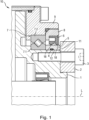
- FIG. 1 shows a section through an output bearing arrangement 10 according to the invention.
- the output bearing arrangement 10 comprises an output shaft 1 and a joint element 2 clamped to the output shaft 1 by means of a clamping device.
- the joint element 2 is thus screwed to the output shaft 1 by means of the at least one screw 3 .
- the output shaft 1 is rotatably supported by an output bearing 7 .
- the output shaft 1 is preferably mounted by means of a single roller bearing, for example a cross roller bearing, a four-point bearing or a double-row angular contact ball bearing. Both the inner ring 7.1 and the outer ring 7.2 of the output bearing 7 must then be guided radially and axially.
- a spacer sleeve 5 is arranged axially between the inner ring 7 . 1 of the output bearing 7 and the joint element 2 .
- the inner ring 7 . 1 of the output bearing 7 is braced or clamped to the output shaft 1 via the spacer sleeve 5 by means of the joint element 2 and the screw or screws 3 .
- An axial force can thus be transmitted from the output-side joint element 2 to the output shaft 1 via the spacer sleeve 5 and the bearing inner ring 7 .
- the spacer sleeve to be formed integrally with the joint element.
- a sealing element 6 is arranged on the spacer sleeve 5, which radially encloses the spacer sleeve 5 and seals the bearing interface.
- the sealing element 6 preferably has two contact areas 18 with which it rests on the spacer sleeve 5 .
- the contact areas 18 are preferably designed as annular areas.
- the outer surface of the spacer sleeve 5 is thus designed as a running surface for the dynamic sealing element 6 .
- the spacer sleeve 5 protrudes axially in the direction of the joint element 2 beyond the end face 11 of the output shaft 1 . As a result, the joint element 2 bears against both the spacer sleeve 5 and at least a partial area of the output shaft 1 .
- a further sealing component 4 is arranged between the spacer sleeve 5 and the output shaft 1 .
- a groove 12 is provided in the spacer sleeve 5, in which the further sealing component 4 is arranged.
- the further sealing component 4 is preferably designed as an O-ring.
- a torsion between the output shaft 1 and the joint element 2 is caused on the one hand by a frictional connection between the joint element 2 and the output shaft 1 and on the other hand by a frictional connection between joint element 2 and spacer sleeve 5, spacer sleeve 5 and inner ring 7.1 of the output bearing 7 and inner ring 7.1 of the output bearing 7 and the output shaft 1 transmitted.
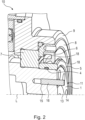
- FIG 2 12 shows the initial bearing assembly 10.
- FIG 1 without the hinge element.
- the output shaft 1 has a central elevation 13 on its end face 11 .
- the central elevation 13 is preferably cylindrical and is formed by the fact that the output shaft 1 is formed slightly set back along its circumference, for example by 0.2 mm.
- bores 14 are formed in the output shaft. The screws with which the joint element is screwed to the output shaft 1 are accommodated in these bores 14 .
- at least one hole 15 can be formed in the output shaft 1 starting from the end face 11 .
- a pin 16 is accommodated in this hole 15 and is used to fix the joint element to the output shaft 1 .
- the spacer sleeve 5 is preferably made of steel, and the output shaft 1 is preferably made of aluminum.
- the spacer sleeve 5 can also be pressed or glued or screwed onto the output shaft 1 . It would also be conceivable that the spacer sleeve and the output shaft consist of the same material, in particular steel.
- the sealing element 6 is preferably made of rubber and runs on the spacer sleeve 5. If the spacer sleeve 5 is made of steel, the friction on the rubber seal causes less abrasion than, for example, on an aluminum component.
- the spacer sleeve 5 protrudes slightly beyond the end face 11 of the output shaft 1 in the axial direction, ie in the direction of the longitudinal axis L of the output shaft 1 .
- the ring element 8 is preferably screwed into the bearing cap 9 via a fine thread and fixes the upper part, i.e. the outer ring 7.2 of the starting bearing 7.
- FIG 3 a first embodiment for fastening the joint element 2 to the output shaft 1 is shown.
- the output shaft 1 has the central elevation 13 described above, against which the joint element 2 rests with a central area.
- the spacer sleeve 5 protrudes axially in the direction of the longitudinal axis L of the output shaft 1 beyond the end face 11 of the output shaft 1 .
- the joint element 2 is therefore also in contact with the spacer sleeve 5, for example with an outer area.
- a shoulder 17 can be formed in the spacer element 2 for this purpose.
- the screws 3 which axially clamp the joint element 2 to the output shaft 1 are arranged along the circumference of the output shaft 1 .
- part of a torque that occurs is transmitted from the joint element 2 to the spacer sleeve 5 and another part of the torque that occurs is transmitted from the joint element 2 to the central elevation 13 of the output shaft 1 .
- figure 4 shows a further embodiment for fastening the joint element 2 to the output shaft 1.
- the joint element 2 is thus only in contact with the spacer sleeve 5 .
- a central support in the center of the joint element 2 is missing.
- a shoulder 17 can be formed in the joint element 2 with which the joint element 2 rests on the spacer sleeve 5 .
- the bores 14 are formed along the circumference of the output shaft 1 so that the bolts 3 are also arranged along the circumference of the output shaft 1 .
- the joint element 2 can thus bend through to the center of the output shaft 1 like a bending beam. This configuration of the joint element 2 as a bending beam prestresses the screw connection and reduces the risk of the screw connection becoming loose during operation of the joint.
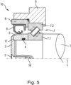
- FIG. 5 shows yet another embodiment for fastening the joint element 2 to the output shaft 1.
- the output shaft 1 does not have a central elevation on the end face.
- the joint element 2 in turn rests only on the spacer sleeve 5 .
- the joint element 2 has a shoulder 17 with which it bears against the spacer sleeve 5 .
- At least one bore 14 is formed in the center of the output shaft 1 , for example lying on the longitudinal axis L of the output shaft 1 .
- the screw 3 is thus arranged in the center of the joint element 2 . It can also be provided that several screws are arranged in the center of the joint element and thus several bores are also formed in the center of the output shaft.
- the joint element 2 has a opposite to the embodiment 4 longer bending beam is formed, which preloads the screw connection between the joint element 2 and the output shaft 1 more, whereby the risk that the screw connection between the joint element 2 and the output shaft 1 loosens during operation of the joint is reduced even further.
Landscapes
- Engineering & Computer Science (AREA)
- General Engineering & Computer Science (AREA)
- Mechanical Engineering (AREA)
- Robotics (AREA)
- Mounting Of Bearings Or Others (AREA)
- Support Of The Bearing (AREA)
Priority Applications (3)
| Application Number | Priority Date | Filing Date | Title |
|---|---|---|---|
| EP21192350.3A EP4137710A1 (fr) | 2021-08-20 | 2021-08-20 | Agencement de paliers de sortie pour un entraînement articulé, en particulier pour un entraînement articulé de robot |
| PCT/EP2022/073169 WO2023021180A1 (fr) | 2021-08-20 | 2022-08-19 | Ensemble palier de sortie pour un entraînement d'articulation, en particulier un entraînement d'articulation de robot |
| EP22768352.1A EP4388211B1 (fr) | 2021-08-20 | 2022-08-19 | Agencement de paliers de sortie pour un entraînement articulé, en particulier pour un entraînement articulé de robot |
Applications Claiming Priority (1)
| Application Number | Priority Date | Filing Date | Title |
|---|---|---|---|
| EP21192350.3A EP4137710A1 (fr) | 2021-08-20 | 2021-08-20 | Agencement de paliers de sortie pour un entraînement articulé, en particulier pour un entraînement articulé de robot |
Publications (1)
| Publication Number | Publication Date |
|---|---|
| EP4137710A1 true EP4137710A1 (fr) | 2023-02-22 |
Family
ID=77431193
Family Applications (2)
| Application Number | Title | Priority Date | Filing Date |
|---|---|---|---|
| EP21192350.3A Withdrawn EP4137710A1 (fr) | 2021-08-20 | 2021-08-20 | Agencement de paliers de sortie pour un entraînement articulé, en particulier pour un entraînement articulé de robot |
| EP22768352.1A Active EP4388211B1 (fr) | 2021-08-20 | 2022-08-19 | Agencement de paliers de sortie pour un entraînement articulé, en particulier pour un entraînement articulé de robot |
Family Applications After (1)
| Application Number | Title | Priority Date | Filing Date |
|---|---|---|---|
| EP22768352.1A Active EP4388211B1 (fr) | 2021-08-20 | 2022-08-19 | Agencement de paliers de sortie pour un entraînement articulé, en particulier pour un entraînement articulé de robot |
Country Status (2)
| Country | Link |
|---|---|
| EP (2) | EP4137710A1 (fr) |
| WO (1) | WO2023021180A1 (fr) |
Citations (4)
| Publication number | Priority date | Publication date | Assignee | Title |
|---|---|---|---|---|
| DE3601456A1 (de) * | 1985-01-22 | 1986-07-24 | GMF Robotics Corp., Troy, Mich. | Mechanischer gelenkmechanismus |
| DE102005035182A1 (de) | 2004-07-27 | 2006-03-02 | Sumitomo Heavy Industries, Ltd. | Untersetzer mit intern ineinander greifendem Planetengetriebemechanismus und Vorrichtung, welche den Untersetzer enthält |
| US20120034022A1 (en) * | 2010-08-05 | 2012-02-09 | Hon Hai Precision Industry Co., Ltd. | Robotic arm assembly |
| KR20170143396A (ko) | 2016-06-21 | 2017-12-29 | 현대로보틱스주식회사 | 로봇 관절 구조 |
-
2021
- 2021-08-20 EP EP21192350.3A patent/EP4137710A1/fr not_active Withdrawn
-
2022
- 2022-08-19 EP EP22768352.1A patent/EP4388211B1/fr active Active
- 2022-08-19 WO PCT/EP2022/073169 patent/WO2023021180A1/fr not_active Ceased
Patent Citations (4)
| Publication number | Priority date | Publication date | Assignee | Title |
|---|---|---|---|---|
| DE3601456A1 (de) * | 1985-01-22 | 1986-07-24 | GMF Robotics Corp., Troy, Mich. | Mechanischer gelenkmechanismus |
| DE102005035182A1 (de) | 2004-07-27 | 2006-03-02 | Sumitomo Heavy Industries, Ltd. | Untersetzer mit intern ineinander greifendem Planetengetriebemechanismus und Vorrichtung, welche den Untersetzer enthält |
| US20120034022A1 (en) * | 2010-08-05 | 2012-02-09 | Hon Hai Precision Industry Co., Ltd. | Robotic arm assembly |
| KR20170143396A (ko) | 2016-06-21 | 2017-12-29 | 현대로보틱스주식회사 | 로봇 관절 구조 |
Also Published As
| Publication number | Publication date |
|---|---|
| EP4388211B1 (fr) | 2026-03-25 |
| EP4388211A1 (fr) | 2024-06-26 |
| WO2023021180A1 (fr) | 2023-02-23 |
Similar Documents
| Publication | Publication Date | Title |
|---|---|---|
| EP2986485B1 (fr) | Double rondelle ondulée comprenant une couche intermédiaire d'amortissement | |
| EP3277557B1 (fr) | Système vis-écrou à billes et direction de véhicule automobile équipée de ce système | |
| EP2768717B1 (fr) | Direction électromécanique de véhicule à moteur | |
| DE2424262A1 (de) | Gewindelose spannvorrichtung | |
| WO2005028217A1 (fr) | Ensemble moyeu de roue/joint tournant | |
| DE1450122A1 (de) | Praezisions-Wellenbund und diesen verwendendes Praezisions-Getrieberad | |
| DE2219720A1 (de) | Lagerschale für ein Wellengelenk, beispielsweise Kreuzgelenk | |
| DE10235280A1 (de) | Planetengetriebe | |
| DE69703347T2 (de) | Übertragungsgelenkkreuz und entsprechendes übertragungsgelenk | |
| EP3384183B1 (fr) | Porte-satellites pour étage d'engrenage d'un engrenage planétaire et procédé de précontrainte | |
| DE1775336C3 (de) | Lageranordnung | |
| EP4388211B1 (fr) | Agencement de paliers de sortie pour un entraînement articulé, en particulier pour un entraînement articulé de robot | |
| LU86144A1 (de) | Vorrichtung zum befestigen eines lagers auf einer welle | |
| EP3819136A1 (fr) | Unite de roulement de roue pour un vehicule a moteur et procede de fabrication d'un unite de roulement de roue | |
| DE2612272A1 (de) | Axial-schraegkugellager | |
| DE4110814A1 (de) | Hubschrauber-hauptrotor | |
| DE4301178C2 (de) | Kreuzzapfengelenk einer zur Übertragung hoher Drehmomente geeigneten Gelenkwelle | |
| DE10202203B4 (de) | Radlagerbefestigung, insbesondere für ein Kraftfahrzeug | |
| DE3610283A1 (de) | Gelenkverbindung | |
| DE60131589T2 (de) | Untersetzungsgetriebe | |
| DE102016103877B4 (de) | Motorlagerschild | |
| DE2942531C2 (de) | Spannvorrichtung zur Befestigung eines Nabenansatzes auf einer Welle | |
| EP3613670B1 (fr) | Dispositif de transmission de force pour un giravion | |
| DE102010003722A1 (de) | Einrichtung zur axialen Sicherung einer Doppelgelenkwelle einer lenkbaren Antriebsachse | |
| DE3616763A1 (de) | Vorichtung zum starren verbinden eines auf einer welle angeordneten bauelementes |
Legal Events
| Date | Code | Title | Description |
|---|---|---|---|
| PUAI | Public reference made under article 153(3) epc to a published international application that has entered the european phase |
Free format text: ORIGINAL CODE: 0009012 |
|
| STAA | Information on the status of an ep patent application or granted ep patent |
Free format text: STATUS: THE APPLICATION HAS BEEN PUBLISHED |
|
| AK | Designated contracting states |
Kind code of ref document: A1 Designated state(s): AL AT BE BG CH CY CZ DE DK EE ES FI FR GB GR HR HU IE IS IT LI LT LU LV MC MK MT NL NO PL PT RO RS SE SI SK SM TR |
|
| STAA | Information on the status of an ep patent application or granted ep patent |
Free format text: STATUS: THE APPLICATION IS DEEMED TO BE WITHDRAWN |
|
| 18D | Application deemed to be withdrawn |
Effective date: 20230823 |