EP4137716A1 - Power transmission device - Google Patents
Power transmission device Download PDFInfo
- Publication number
- EP4137716A1 EP4137716A1 EP20931565.4A EP20931565A EP4137716A1 EP 4137716 A1 EP4137716 A1 EP 4137716A1 EP 20931565 A EP20931565 A EP 20931565A EP 4137716 A1 EP4137716 A1 EP 4137716A1
- Authority
- EP
- European Patent Office
- Prior art keywords
- clutch
- driving
- clutch plates
- auxiliary
- driven
- Prior art date
- Legal status (The legal status is an assumption and is not a legal conclusion. Google has not performed a legal analysis and makes no representation as to the accuracy of the status listed.)
- Pending
Links
Images










Classifications
-
- F—MECHANICAL ENGINEERING; LIGHTING; HEATING; WEAPONS; BLASTING
- F16—ENGINEERING ELEMENTS AND UNITS; GENERAL MEASURES FOR PRODUCING AND MAINTAINING EFFECTIVE FUNCTIONING OF MACHINES OR INSTALLATIONS; THERMAL INSULATION IN GENERAL
- F16D—COUPLINGS FOR TRANSMITTING ROTATION; CLUTCHES; BRAKES
- F16D13/00—Friction clutches
- F16D13/22—Friction clutches with axially-movable clutching members
- F16D13/38—Friction clutches with axially-movable clutching members with flat clutching surfaces, e.g. discs
- F16D13/52—Clutches with multiple lamellae ; Clutches in which three or more axially moveable members are fixed alternately to the shafts to be coupled and are pressed from one side towards an axially-located member
- F16D13/54—Clutches with multiple lamellae ; Clutches in which three or more axially moveable members are fixed alternately to the shafts to be coupled and are pressed from one side towards an axially-located member with means for increasing the effective force between the actuating sleeve or equivalent member and the pressure member
-
- F—MECHANICAL ENGINEERING; LIGHTING; HEATING; WEAPONS; BLASTING
- F16—ENGINEERING ELEMENTS AND UNITS; GENERAL MEASURES FOR PRODUCING AND MAINTAINING EFFECTIVE FUNCTIONING OF MACHINES OR INSTALLATIONS; THERMAL INSULATION IN GENERAL
- F16D—COUPLINGS FOR TRANSMITTING ROTATION; CLUTCHES; BRAKES
- F16D43/00—Automatic clutches
- F16D43/02—Automatic clutches actuated entirely mechanically
- F16D43/04—Automatic clutches actuated entirely mechanically controlled by angular speed
- F16D43/06—Automatic clutches actuated entirely mechanically controlled by angular speed with centrifugal masses actuating axially a movable pressure ring or the like
- F16D43/08—Automatic clutches actuated entirely mechanically controlled by angular speed with centrifugal masses actuating axially a movable pressure ring or the like the pressure ring actuating friction plates, cones or similar axially-movable friction surfaces
- F16D43/12—Automatic clutches actuated entirely mechanically controlled by angular speed with centrifugal masses actuating axially a movable pressure ring or the like the pressure ring actuating friction plates, cones or similar axially-movable friction surfaces the centrifugal masses acting on, or forming a part of, an actuating mechanism by which the pressure ring can also be actuated independently of the masses
-
- B—PERFORMING OPERATIONS; TRANSPORTING
- B60—VEHICLES IN GENERAL
- B60K—ARRANGEMENT OR MOUNTING OF PROPULSION UNITS OR OF TRANSMISSIONS IN VEHICLES; ARRANGEMENT OR MOUNTING OF PLURAL DIVERSE PRIME-MOVERS IN VEHICLES; AUXILIARY DRIVES FOR VEHICLES; INSTRUMENTATION OR DASHBOARDS FOR VEHICLES; ARRANGEMENTS IN CONNECTION WITH COOLING, AIR INTAKE, GAS EXHAUST OR FUEL SUPPLY OF PROPULSION UNITS IN VEHICLES
- B60K17/00—Arrangement or mounting of transmissions in vehicles
- B60K17/02—Arrangement or mounting of transmissions in vehicles characterised by arrangement, location, or kind of clutch
-
- F—MECHANICAL ENGINEERING; LIGHTING; HEATING; WEAPONS; BLASTING
- F16—ENGINEERING ELEMENTS AND UNITS; GENERAL MEASURES FOR PRODUCING AND MAINTAINING EFFECTIVE FUNCTIONING OF MACHINES OR INSTALLATIONS; THERMAL INSULATION IN GENERAL
- F16D—COUPLINGS FOR TRANSMITTING ROTATION; CLUTCHES; BRAKES
- F16D13/00—Friction clutches
- F16D13/22—Friction clutches with axially-movable clutching members
- F16D13/38—Friction clutches with axially-movable clutching members with flat clutching surfaces, e.g. discs
- F16D13/52—Clutches with multiple lamellae ; Clutches in which three or more axially moveable members are fixed alternately to the shafts to be coupled and are pressed from one side towards an axially-located member
-
- F—MECHANICAL ENGINEERING; LIGHTING; HEATING; WEAPONS; BLASTING
- F16—ENGINEERING ELEMENTS AND UNITS; GENERAL MEASURES FOR PRODUCING AND MAINTAINING EFFECTIVE FUNCTIONING OF MACHINES OR INSTALLATIONS; THERMAL INSULATION IN GENERAL
- F16D—COUPLINGS FOR TRANSMITTING ROTATION; CLUTCHES; BRAKES
- F16D47/00—Systems of clutches, or clutches and couplings, comprising devices of types grouped under at least two of the following sets of groups: F16D1/00 - F16D9/00, F16D11/00 - F16D23/00, F16D25/00 - F16D29/00, F16D31/00 - F16D39/00, F16D41/00 - F16D45/00
-
- F—MECHANICAL ENGINEERING; LIGHTING; HEATING; WEAPONS; BLASTING
- F16—ENGINEERING ELEMENTS AND UNITS; GENERAL MEASURES FOR PRODUCING AND MAINTAINING EFFECTIVE FUNCTIONING OF MACHINES OR INSTALLATIONS; THERMAL INSULATION IN GENERAL
- F16D—COUPLINGS FOR TRANSMITTING ROTATION; CLUTCHES; BRAKES
- F16D13/00—Friction clutches
- F16D13/22—Friction clutches with axially-movable clutching members
- F16D13/38—Friction clutches with axially-movable clutching members with flat clutching surfaces, e.g. discs
- F16D13/52—Clutches with multiple lamellae ; Clutches in which three or more axially moveable members are fixed alternately to the shafts to be coupled and are pressed from one side towards an axially-located member
- F16D13/54—Clutches with multiple lamellae ; Clutches in which three or more axially moveable members are fixed alternately to the shafts to be coupled and are pressed from one side towards an axially-located member with means for increasing the effective force between the actuating sleeve or equivalent member and the pressure member
- F16D13/56—Clutches with multiple lamellae ; Clutches in which three or more axially moveable members are fixed alternately to the shafts to be coupled and are pressed from one side towards an axially-located member with means for increasing the effective force between the actuating sleeve or equivalent member and the pressure member in which the clutching pressure is produced by springs only
- F16D2013/565—Clutches with multiple lamellae ; Clutches in which three or more axially moveable members are fixed alternately to the shafts to be coupled and are pressed from one side towards an axially-located member with means for increasing the effective force between the actuating sleeve or equivalent member and the pressure member in which the clutching pressure is produced by springs only with means for releasing the clutch pressure in case of back torque
-
- F—MECHANICAL ENGINEERING; LIGHTING; HEATING; WEAPONS; BLASTING
- F16—ENGINEERING ELEMENTS AND UNITS; GENERAL MEASURES FOR PRODUCING AND MAINTAINING EFFECTIVE FUNCTIONING OF MACHINES OR INSTALLATIONS; THERMAL INSULATION IN GENERAL
- F16D—COUPLINGS FOR TRANSMITTING ROTATION; CLUTCHES; BRAKES
- F16D2300/00—Special features for couplings or clutches
- F16D2300/10—Surface characteristics; Details related to material surfaces
-
- F—MECHANICAL ENGINEERING; LIGHTING; HEATING; WEAPONS; BLASTING
- F16—ENGINEERING ELEMENTS AND UNITS; GENERAL MEASURES FOR PRODUCING AND MAINTAINING EFFECTIVE FUNCTIONING OF MACHINES OR INSTALLATIONS; THERMAL INSULATION IN GENERAL
- F16D—COUPLINGS FOR TRANSMITTING ROTATION; CLUTCHES; BRAKES
- F16D2300/00—Special features for couplings or clutches
- F16D2300/12—Mounting or assembling
Definitions
- the present invention relates to a power transmission apparatus that is able to freely transmit a rotational force of an input member to an output member or cut off the rotational force.
- a power transmission apparatus included in a motorcycle freely transmits a driving force of an engine to a transmission and a driving wheel or cuts off the driving force.
- a power transmission apparatus includes: an input member connected to an engine; an output member connected to a transmission and a driving wheel; a clutch member connected to the output member; and a pressure member that is able to move close to or away from the clutch member. Bringing the pressure member close to the clutch member presses driving and driven clutch plates against each other so as to transmit power therebetween. Moving the pressure member away from the clutch member releases a pressing force exerted on the driving and driven clutch plates so as to cut off transmission of the power therebetween.
- a power transmission apparatus known in the art includes a centrifugal clutch means including a weight member that moves from a radially inner position of a groove to a radially outer position thereof with centrifugal force produced by rotation of a clutch housing and is thus able to press driving and driven clutch plates against each other.
- the power transmission apparatus known in the art is able to apply centrifugal force to the weight member in accordance with the rotation of the clutch housing caused by driving of an engine and is thus able to press the driving and driven clutch plates against each other so as to transmit a driving force of the engine to a wheel.
- Patent Literature 1 WO 2013/183588
- the power transmission apparatus known in the art may require increasing the number of driving clutch plates and the number of driven clutch plates in order to achieve a clutch capacity required for a multiple-plate clutch.
- the required clutch capacity is achieved by simply increasing the number of driving clutch plates and the number of driven clutch plates in a stacking direction of the multiple-plate clutch, the size of the apparatus in an axial direction may increase, which may make the apparatus larger than a space in a vehicle where the apparatus is installable.
- Such a problem may occur not only in apparatuses including weight members but also in general multiple-plate clutch type power transmission apparatuses including driving and driven clutch plates.
- the present invention has been made in view of the above-described circumstances and its object is to provide a power transmission apparatus that is able to have an increased clutch capacity while being prevented from increasing in size in an axial direction.
- the invention of claim 1 provides a power transmission apparatus including: a clutch housing that rotates together with an input member that rotates with a driving force of an engine of a vehicle, the clutch housing having a plurality of driving clutch plates attached thereto; a clutch member having a plurality of driven clutch plates attached thereto, the driven clutch plates being arranged alternately with the driving clutch plates attached to the clutch housing, the clutch member being connected to an output member that is able to rotate a wheel of the vehicle; and a pressure member movable between an operating position where the driving and driven clutch plates are pressed against each other so as to enable transmission of the driving force of the engine to the wheel and a non-operating position where a pressing force exerted on the driving and driven clutch plates is released so as to cut off transmission of the driving force of the engine to the wheel.
- An auxiliary clutch plate different in diameter from the driving and driven clutch plates is disposed in the clutch housing.
- the driving and driven clutch plates are pressed against each other, the auxiliary clutch plate is pressed so as to enable transmission of the driving force of the engine to the wheel.
- a pressing force exerted on the auxiliary clutch plate is released so as to cut off transmission of the driving force of the engine to the wheel.
- the invention of claim 2 is based on the power transmission apparatus according to claim 1, wherein the power transmission apparatus includes a centrifugal clutch means including a weight member movable from a radially inner position to a radially outer position with centrifugal force produced by rotation of the clutch housing.
- the centrifugal clutch means presses the auxiliary clutch plate concurrently with pressing the driving and driven clutch plates against each other so as to enable transmission of the driving force of the engine to the wheel.
- the centrifugal clutch means releases the pressing force exerted on the auxiliary clutch plate concurrently with releasing the pressing force exerted on the driving and driven clutch plates so as to cut off transmission of the driving force of the engine to the wheel.
- the invention of claim 3 is based on the power transmission apparatus according to claim 2, wherein the centrifugal clutch means includes: a holding member holding the weight member such that the weight member is movable between the radially inner position and the radially outer position; a pressing member to press the driving and driven clutch plates against each other by moving in a stacking direction of the driving and driven clutch plates in response to movement of the weight member from the radially inner position to the radially outer position; and an urging member urging the weight member from the radially outer position to the radially inner position.
- the centrifugal clutch means includes: a holding member holding the weight member such that the weight member is movable between the radially inner position and the radially outer position; a pressing member to press the driving and driven clutch plates against each other by moving in a stacking direction of the driving and driven clutch plates in response to movement of the weight member from the radially inner position to the radially outer position; and an urging member urging the weight member from the radially outer position to the
- the invention of claim 4 is based on the power transmission apparatus according to any one of claims 1 to 3, wherein the auxiliary clutch plate is disposed such that the auxiliary clutch plate overlaps, in an axial direction of the clutch housing, with a region where the driving and driven clutch plates are stacked.
- the invention of claim 5 is based on the power transmission apparatus according to any one of claims 1 to 4, wherein the auxiliary clutch plate includes a plurality of clutch plates.
- the auxiliary clutch plate different in diameter from the driving and driven clutch plates is disposed in the clutch housing.
- the driving and driven clutch plates are pressed against each other, the auxiliary clutch plate is pressed so as to enable transmission of the driving force of the engine to the wheel.
- the pressing force exerted on the driving and driven clutch plates is released, the pressing force exerted on the auxiliary clutch plate is released so as to cut off transmission of the driving force of the engine to the wheel. Consequently, this invention is able to increase a clutch capacity while preventing the apparatus from increasing in size in the axial direction.
- this invention when the weight member is located at the radially outer position, one of the pressing member and the holding member presses the driving and driven clutch plates against each other, and the other one of the pressing member and the holding member presses the auxiliary clutch plate. Consequently, with the pressing member and the holding member included in the centrifugal clutch means, this invention is able to press the auxiliary clutch plate or release the pressing force exerted thereon, in addition to pressing the driving and driven clutch plates against each other or releasing the pressing force exerted thereon.
- the auxiliary clutch plate is disposed such that the auxiliary clutch plate overlaps, in the axial direction of the clutch housing, with the region where the driving and driven clutch plates are stacked. Consequently, this invention is able to reliably prevent the apparatus from increasing in size in the axial direction.
- the auxiliary clutch plate includes a plurality of clutch plates. Consequently, this invention is able to increase a clutch capacity of the auxiliary clutch plate to any desired level.
- a power transmission apparatus K is disposed in a vehicle so as to freely transmit a driving force of an engine E to a driving wheel T through a transmission M or cut off the driving force.
- FIGS. 21 a power transmission apparatus K according to the present embodiment is disposed in a vehicle so as to freely transmit a driving force of an engine E to a driving wheel T through a transmission M or cut off the driving force.
- the power transmission apparatus K includes: a clutch housing 2 provided with an input gear 1 (which is an input member) that rotates with the driving force of the engine E of the vehicle; an output shaft 3 (which is an output member) connected to the transmission M; a clutch member (which includes a first clutch member 4a and a second clutch member 4b); a pressure member 5; a plurality of driving clutch plates 6; a plurality of driven clutch plates 7; a centrifugal clutch means 9 including weight members 10; and an auxiliary clutch plate 17.
- the input gear 1 is rotatable around the output shaft 3 upon receiving a driving force (or a rotational force) transmitted from the engine E.
- the input gear 1 is connected to the clutch housing 2 with a fastener, such as a rivet.
- the clutch housing 2 is a cylindrical member with an opening defined at its right end in FIGS. 2 and 3 and is connected to the input gear 1.
- the clutch housing 2 is rotatable together with rotation of the input gear 1 with the driving force of the engine E.
- the clutch housing 2 is circumferentially provided with a plurality of cut-outs 2a.
- the driving clutch plates 6 are fitted to the cut-outs 2A and thus attached to the clutch housing 2.
- the driving clutch plates 6 are each made of a substantially annular plate material.
- the driving clutch plates 6 are rotatable together with rotation of the clutch housing 2.
- the driving clutch plates 6 are slidable in an axial direction (which corresponds to a right-left direction in FIGS. 2 and 3 ).
- the driven clutch plates 7 are attached to the clutch member (which includes the first clutch member 4a and the second clutch member 4b).
- the driven clutch plates 7 are arranged alternately with the driving clutch plates 6 attached to the clutch housing 2.
- the clutch member is connected to the output shaft 3 (i.e., the output member) that is able to rotate the driving wheel T through the transmission M of the vehicle.
- the clutch member is provided by assembling two members, i.e., the first clutch member 4a and the second clutch member 4b, to each other.
- the output shaft 3 is inserted through an insertion hole (see FIGS. 5 and 6 ) defined in the center of the first clutch member 4a.
- a gear provided on the first clutch member 4a and a gear provided on the output shaft 3 mesh with each other so as to be connected to each other in the direction of rotation.
- the first clutch member 4a is provided with: inclined surfaces 4aa each defining a pressing assist cam; and inclined surfaces 4ab each defining a back torque limiter cam.
- the reference signs "4ac" in FIGS. 5 and 6 each indicate a boss provided with an insertion hole for a bolt B for connection between the first clutch member 4a and a securing member 8.
- the second clutch member 4b is an annular member provided with a flange 4bb.
- the driven clutch plates 7 are spline-fitted to a spline-fitting portion 4ba provided on the outer peripheral surface of the second clutch member 4b and are thus attached to the second clutch member 4b.
- the pressure member 5 is assembled to the clutch member (which includes the first clutch member 4a and the second clutch member 4b) such that the driving and driven clutch plates 6 and 7 are alternately stacked and secured between a flange 5c of the pressure member 5 and the flange 4bb of the second clutch member 4b.
- the pressure member 5 is a disk member provided with the flange 5c extending along the peripheral edge of the pressure member 5.
- the pressure member 5 is movable between: an operating position where the driving and driven clutch plates 6 and 7 are pressed against each other so as to enable transmission of the driving force of the engine E to the wheel; and a non-operating position where a pressing force exerted on the driving and driven clutch plates 6 and 7 is released so as to cut off transmission of the driving force of the engine E to the wheel.
- the spline-fitting portion 4ba provided on the second clutch member 4b forms integral projections and depressions along substantially the entire outer peripheral side surface of the second clutch member 4b. Fitting the driven clutch plates 7 to recessed grooves that define the spline-fitting portion 4ba restricts movement of the driven clutch plates 7 in the direction of rotation while allowing movement of the driven clutch plates 7 in the axial direction relative to the second clutch member 4b.
- the driven clutch plates 7 are rotatable together with the second clutch member 4b.
- the driven clutch plates 7 are stacked alternately with the driving clutch plates 6, making it possible to allow the clutch plates 6 and 7 adjacent to each other to be pressed against each other or release the pressing force exerted thereon. In other words, the clutch plates 6 and 7 are allowed to slide in the axial direction of the second clutch member 4b. Engaging a clutch by pressing the clutch plates (6a, 6b, 7a, 7b) against each other enables a rotational force of the clutch housing 2 to be transmitted to the output shaft 3 through the second clutch member 4b and the first clutch member 4a.
- Disengaging the clutch by releasing the pressing force exerted on the clutch plates (6a, 6b, 7a, 7b) causes the first clutch member 4a and the second clutch member 4b to stop following the rotation of the clutch housing 2 such that no rotational force will be transmitted to the output shaft 3.
- a state where the driving and driven clutch plates 6 and 7 are pressed against each other enables transmission of a rotational force (i.e., the driving force of the engine E), which is received by the clutch housing 2, to the driving wheel (or the transmission M) through the output shaft 3 (i.e., the output member), and a state where the driving and driven clutch plates 6 and 7 are not pressed against each other makes it possible to cut off transmission of the rotational force (or the driving force of the engine E), which is received by the clutch housing 2, to the output shaft 3 (i.e., the output member).
- a rotational force i.e., the driving force of the engine E
- the pressure member 5 is circumferentially provided with a plurality of fitting holes 5d (i.e., three fitting holes 5d in the present embodiment).
- a clutch spring S is fitted into each of the fitting holes 5d.
- one end of each clutch spring S housed in the associated fitting hole 5d is in abutment with the securing member 8, such that each clutch spring S urges the pressure member 5 in a direction in which the driving and driven clutch plates 6 and 7 are to be pressed against each other.
- Operating a clutch operation means (not illustrated) makes it possible to press the driving and driven clutch plates 6 and 7 against each other or stop pressing the driving and driven clutch plates 6 and 7 against each other.
- the first clutch member 4a is provided with the inclined surfaces 4aa and 4ab
- the pressure member 5 is provided with inclined surfaces 5a and 5b respectively facing the inclined surfaces 4aa and 4ab.
- each inclined surface 4aa comes into abutment with the associated inclined surface 5a so as to provide the pressing assist cam
- each inclined surface 4ab comes into abutment with the associated inclined surface 5b so as to provide the back torque limiter cam.
- the rotation speed of the engine E is increased and the resulting rotational force received by the input gear 1 and the clutch housing 2 is transmittable to the output shaft 3 through the first clutch member 4a and the second clutch member 4b (which means that the weight members 10 are each located at a radially outer position).
- the rotational force is applied to the pressure member 5 in an a-direction, which exerts a force on the pressure member 5 in a c-direction in FIG. 20a under the action of each pressing assist cam.
- the pressure member 5 is thus moved in a direction in which its flange 5c comes closer to the flange 4bb of the second clutch member 4b (i.e., leftward in FIGS. 2 and 3 ) so as to increase the pressing force exerted on the driving and driven clutch plates 6 and 7.
- the centrifugal clutch means 9 includes the weight members 10 each movable from a radially inner position (see FIG. 18 ) to the radially outer position (see FIG. 19 ) with centrifugal force produced by rotation of the clutch housing 2.
- the centrifugal clutch means 9 presses the driving and driven clutch plates 6 and 7 against each other so as to enable transmission of the driving force of the engine E to the wheel (i.e., the driving wheel T).
- the centrifugal clutch means 9 releases the pressing force exerted on the driving and driven clutch plates 6 and 7 so as to cut off transmission of the driving force of the engine E to the wheel (i.e., the driving wheel T).
- the centrifugal clutch means 9 includes: the weight members 10, each of which is a substantially symmetrical polygonal member; a holding member 11 having a supporting member 13 attached thereto; a pressing member 12; first spherical members 14; second spherical members 15; and urging members 16, each of which is a coil spring.
- the holding member 11 and the pressing member 12 are each circumferentially provided with a plurality of protrusions.
- the protrusions are fitted to the cut-outs 2a of the clutch housing 2 such that the holding member 11 and the pressing member 12 are attached to the clutch housing 2. Accordingly, the holding member 11 and the pressing member 12 are each movable in the axial direction of the clutch housing 2 and in engagement with the clutch housing 2 in the direction of rotation so as to be rotatable together with the clutch housing 2.
- each weight member 10 is a substantially symmetrical polygonal member including a first surface X and a second surface Y. As illustrated in FIGS. 16 and 17 , each weight member 10 includes: through holes 10a passing through the weight member 10 from the first surface X to the second surface Y; insertion portions 10b defined in the second surface Y; and a groove 10c defined in the first surface X. As illustrated in FIGS. 18 and 19 , the weight members 10 are each housed in an associated one of housing portions 11a of the holding member 11. When no centrifugal force is applied to the weight members 10, the weight members 10 are each held at the radially inner position (see FIG. 18 ). Application of centrifugal force to the weight members 10 moves the weight members 10 outward against the urging force of the urging members 16 such that each weight member 10 reaches the radially outer position (see FIG. 19 ).
- the holding member 11 holds the weight members 10 such that each weight member 10 is movable between the radially inner position and the radially outer position.
- the holding member 11 is an annular member.
- the holding member 11 includes: the housing portions 11a which are arranged in the circumferential direction of the holding member 11 and in which the weight members 10 are to be housed; groove geometries 11b defined in the housing portions 11a; and a pushing surface 11c.
- Each housing portion 11a has a recessed shape conforming to the shape and moving range of the associated weight member 10.
- An inner peripheral wall surface 11aa of each housing portion 11a is allowed to abut against first ends of the associated urging members 16.
- the supporting member 13 is secured to a surface of the holding member 11, which is provided with the housing portions 11a. As illustrated in FIG. 14 , the supporting member 13 is provided with radially extending holding portions 13a.
- the holding portions 13a each conform to the groove 10c of the associated weight member 10, so that the weight members 10 are held by the holding member 11.
- the first surface X of each weight member 10 is centrally provided with the groove 10c extending in a direction from the radially inner position to the radially outer position. Causing each holding portion 13a to conform to the associated groove 10c allows the holding member 11 to hold the weight members 10 such that each weight member 10 is movable in a radial direction (i.e., in a direction from the radially inner position to the radially outer position).
- each weight member 10 Movement of each weight member 10 from the radially inner position to the radially outer position causes the pressing member 12 to move in a stacking direction of the driving and driven clutch plates 6 and 7 (i.e., rightward in FIGS. 2 and 3 ) such that the driving and driven clutch plates 6 and 7 are pressed against each other.
- the pressing member 12 is an annular member.
- the pressing member 12 includes: inclined grooves 12a arranged in the circumferential direction of the pressing member 12; groove geometries 12b each defined at a position where the associated inclined groove 12a is defined; and a pushing surface 12c.
- Each inclined groove 12a is defined at a position corresponding to the position of the associated weight member 10.
- Each inclined groove 12a is inclined upward from its inner portion to its outer portion.
- each weight member 10 is held at the radially inner position with the urging force of the associated urging members 16.
- Rotation of the clutch housing 2 applies centrifugal force to the weight members 10 so as to move the weight members 10 along the inclined grooves 12a inclined upward. This moves the pressing member 12 away from the holding member 11 (i.e., in the direction in which the driving and driven clutch plates 6 and 7 are to be pressed against each other).
- each inclined groove 12a is located at a position corresponding to the position of the associated weight member 10 as illustrated in FIGS. 11 and 12 .
- the weight members 10 With centrifugal force, the weight members 10 each move along the inclined grooves 12a from the radially inner position to the radially outer position, which moves the pressing member 12 in a direction indicated by the arrow in FIG. 11 (i.e., rightward in FIG. 11 ).
- the pushing surface 12c of the pressing member 12 thus pushes the driving and driven clutch plates 6 and 7 such that the driving and driven clutch plates 6 and 7 are pressed against each other.
- the resulting reaction force moves the holding member 11 in a direction opposite to the direction indicated by the arrow in FIG. 11 (i.e., leftward in FIG. 11 ), so that the pushing surface 11c of the holding member 11 presses the auxiliary clutch plate 17.
- the weight members 10 are each housed in an associated one of the housing portions 11a arranged in the circumferential direction of the holding member 11 such that the weight members 10 are movable radially.
- More than one urging member 16 i.e., two urging members 16 in the present embodiment
- the inner peripheral wall surface 11aa of each housing portion 11a is a flat surface in abutment with the first ends of the associated urging members 16 such that the urging members 16 are stably securable.
- the weight members 10 are each provided with the tunnel-shaped insertion portions 10b which are openings defined in a surface of each weight member 10 facing the holding member 11 (i.e., the second surface Y in FIG. 17 ) and into which the urging members 16 are inserted such that the urging members 16 are attachable to the associated weight member 10.
- the weight members 10, with the urging members 16 inserted into the insertion portions 10b, are housed in the housing portions 11a of the holding member 11.
- the urging members 16 are thus secured such that each urging member 16 is interposed between the inner peripheral wall surface 11aa of the associated housing portion 11a and the associated weight member 10.
- the urging members 16 are disposed such that the first end of each urging member 16 is in abutment with the associated inner peripheral wall surface 11aa and a second end of each urging member 16 is in abutment with an end wall surface 10ba of the associated insertion portion 10b, making it possible to urge each weight member 10 from the radially outer position to the radially inner position.
- Each first spherical member 14 is a steel ball attached to the associated weight member 10. As illustrated in FIGS. 16 and 17 , each first spherical member 14 is partially protruded from a first opening 10aa (i.e., a small-diameter opening in the first surface X) of the through hole 10a defined in the associated weight member 10 and is in contact with a rolling contact surface of the pressing member 12 so as to be rollable thereon.
- Each second spherical member 15 is a steel ball attached to the associated weight member 10. As illustrated in FIGS.
- each second spherical member 15 is partially protruded from a second opening 10ab (i.e., a large-diameter opening in the second surface Y) of the through hole 10a defined in the associated weight member 10 and is in contact with a rolling contact surface of the holding member 11 so as to be rollable thereon.
- a second opening 10ab i.e., a large-diameter opening in the second surface Y
- the through holes 10a are tapered such that the diameter of each through hole 10a continuously increases from the first opening 10aa (i.e., the small-diameter opening in the first surface X) to the second opening 10ab (i.e., the large-diameter opening in the second surface Y). Disconnection of each first spherical member 14 from the associated through hole 10a is prevented by the outer peripheral edge of one of the first opening 10aa and the second opening 10ab that has a smaller diameter (which is, in the present embodiment, the first opening 10aa in the first surface X).
- the first and second spherical members 14 and 15 are spherical members having different diameters in accordance with the inner diameters of the through holes 10a.
- the second spherical members 15 are larger in diameter than the first spherical members 14.
- the small-diameter first spherical members 14 are each rollable while being in contact with the inner peripheral surface of the associated through hole 10a, and at the same time, disconnection of the small-diameter first spherical members 14 is prevented by the small-diameter opening edges of the through holes 10a.
- disconnection of the second spherical members 15 is prevented by the rolling contact surface of the holding member 11.
- disconnection of the small-diameter first spherical members 14 is prevented by the small-diameter opening edges of the through holes 10a
- disconnection of the large-diameter second spherical members 15 is prevented by the rolling contact surface of the holding member 11 while the second spherical members 15 are partially protruded from the large-diameter openings of the through holes 10a.
- the large-diameter second spherical members 15 are assembled to the weight members 10 such that the second spherical members 15 face the rolling contact surface of the holding member 11.
- the second spherical members 15 may be assembled to the weight members 10 such that the second spherical members 15 face the rolling contact surface of the pressing member 12.
- disconnection of the small-diameter first spherical members 14 is prevented by the small-diameter opening edges of the through holes 10a
- disconnection of the large-diameter second spherical members 15 is prevented by the rolling contact surface of the pressing member 12 while the second spherical members 15 are partially protruded from the large-diameter openings of the through holes 10a.
- the rolling contact surface of the holding member 11 (which is, in the present embodiment, a surface of the holding member 11 on which the second spherical members 15 roll) includes the groove geometries 11b each extending in the direction of movement of the associated weight member 10 (i.e., a direction connecting the radially inner position to the radially outer position).
- the rolling contact surface of the pressing member 12 (which is, in the present embodiment, a surface of the pressing member 12 on which the first spherical members 14 roll) includes the groove geometries 12b each extending in the direction of movement of the associated weight member 10 (i.e., a direction connecting the radially inner position to the radially outer position).
- the first and second spherical members 14 and 15 are provided such that more than one first spherical member 14 and more than one second spherical member 15 are arranged in the circumferential direction of the holding member 11 (i.e., such that two first spherical members 14 and two second spherical members 15 are arranged in the width direction of each weight member 10 in the present embodiment).
- the first spherical members 14 are movable along the groove geometries 12b while rolling within the through holes 10a
- the second spherical members 15 are movable along the groove geometries 11b while rolling within the through holes 10a.
- the auxiliary clutch plate 17 is disposed in the clutch housing 2.
- the auxiliary clutch plate 17 is an annular member different in diameter from the driving and driven clutch plates 6 and 7 (i.e., smaller in diameter than the driving and driven clutch plates 6 and 7 in the present embodiment).
- the output shaft 3 i.e., the output member
- the auxiliary clutch plate 17 includes a pushed surface 17b facing the pushing surface 11c of the holding member 11.
- the auxiliary clutch plate 17 When the weight members 10 are each located at the radially outer position (i.e., when the driving and driven clutch plates 6 and 7 are pressed against each other), the auxiliary clutch plate 17 is able to transmit the driving force of the engine E to the output shaft 3 upon being pushed by the pushing surface 11c of the holding member 11 and pressed against the pushing surface 11c.
- the auxiliary clutch plate 17 When the weight members 10 are each located at the radially inner position (i.e., when the pressing force exerted on the driving and driven clutch plates 6 and 7 is released), the auxiliary clutch plate 17 is able to cut off transmission of the driving force of the engine E to the output shaft 3 upon being relieved of a pressing force applied thereto, owing to a decrease in pushing force exerted by the pushing surface 11c of the holding member 11.
- each inclined groove 12a functions as a cam so as to cause the holding member 11 and the pressing member 12 to move away from each other. Accordingly, the pushing surface 12c of the pressing member 12 presses the driving and driven clutch plates 6 and 7 against each other, and the pushing surface 11c of the holding member 11 pushes the pushed surface 17b of the auxiliary clutch plate 17 such that the pushed surface 17b is pressed against the pushing surface 11c so as to transmit the driving force of the engine E to the driving wheel T.
- a portion of a surface of the first clutch member 4a according to the present embodiment, which faces the pressure member 5, defines an abutment surface 4ad.
- a portion of a surface of the pressure member 5, which faces the first clutch member 4a defines an abutment surface 5e.
- Each weight member 10 of the centrifugal clutch means 9 then further moves from the intermediate position (see FIG. 23 ) to the radially outer position (see FIG. 24 ), and the driving and driven clutch plates 6 and 7 are pushed by the flange 4bb of the second clutch member 4b and thus pressed against each other.
- the pushing force of the flange 4bb is equal to or greater than the urging force of the clutch springs S
- the second clutch member 4b and the pressure member 5 are moved in the axial direction (i.e., rightward in FIGS. 2 and 3 ) relative to the first clutch member 4a, so that the abutment surface 4ad of the first clutch member 4a and the abutment surface 5e of the pressure member 5 are located away from each other.
- FIG. 25 illustrates a state in which the weight members 10 are each located at the radially outer position and the pressure member 5 is located at the non-operating position (i.e., a clutch-disengaged state).
- the auxiliary clutch plate 17 when the driving and driven clutch plates 6 and 7 are pressed against each other, the auxiliary clutch plate 17 is pressed so as to enable transmission of the driving force of the engine E to the wheel (i.e., the driving wheel T).
- the pressing force exerted on the driving and driven clutch plates 6 and 7 is released, the pressing force exerted on the auxiliary clutch plate 17 is released so as to cut off transmission of the driving force of the engine E to the wheel (i.e., the driving wheel T).
- the present embodiment involves providing the centrifugal clutch means 9 including the weight members 10.
- the centrifugal clutch means 9 presses the auxiliary clutch plate 17 concurrently with pressing the driving and driven clutch plates 6 and 7 against each other so as to enable transmission of the driving force of the engine E to the wheel (i.e., the driving wheel T).
- the centrifugal clutch means 9 releases the pressing force exerted on the auxiliary clutch plate 17 concurrently with releasing the pressing force exerted on the driving and driven clutch plates 6 and 7 so as to cut off transmission of the driving force of the engine E to the wheel (i.e., the driving wheel T).
- the centrifugal clutch means 9 may be disposed such that when the weight members 10 are each located at the radially outer position, the pressing member 12 and the holding member 11 move away from each other, the holding member 11 presses the driving and driven clutch plates 6 and 7 against each other, and the pressing member 12 presses the auxiliary clutch plate 17.
- the auxiliary clutch plate 17 different in diameter from the driving and driven clutch plates 6 and 7 is disposed in the clutch housing 2.
- the driving and driven clutch plates 6 and 7 are pressed against each other, the auxiliary clutch plate 17 is pressed so as to enable transmission of the driving force of the engine E to the wheel (i.e., the driving wheel T).
- the pressing force exerted on the driving and driven clutch plates 6 and 7 is released, the pressing force exerted on the auxiliary clutch plate 17 is released so as to cut off transmission of the driving force of the engine E to the wheel (i.e., the driving wheel T).
- the present embodiment is able to increase a clutch capacity while preventing the apparatus from increasing in size in the axial direction.
- the auxiliary clutch plate 17 is disposed radially inward of a region where the driving and driven clutch plates 6 and 7 are stacked (which defines a multiple-plate clutch portion) inside the clutch housing 2. Accordingly, the present embodiment is able to increase a clutch capacity while preventing the apparatus from increasing in size not only in the axial direction but also in a direction perpendicular to the axial direction, and to effectively utilize a radially inner space inside the clutch housing 2.
- the present embodiment involves providing the centrifugal clutch means 9 configured to, when the weight members 10 are each located at the radially outer position, press the auxiliary clutch plate 17 concurrently with pressing the driving and driven clutch plates 6 and 7 against each other so as to enable transmission of the driving force of the engine E to the wheel (i.e., the driving wheel T), and configured to, when the weight members 10 are each located at the radially inner position, release the pressing force exerted on the auxiliary clutch plate 17 concurrently with releasing the pressing force exerted on the driving and driven clutch plates 6 and 7 so as to cut off transmission of the driving force of the engine E to the wheel (i.e., the driving wheel T).
- the present embodiment is able to press the auxiliary clutch plate 17 or release the pressing force exerted thereon, in addition to pressing the driving and driven clutch plates 6 and 7 against each other or releasing the pressing force exerted thereon.
- the present embodiment is able to press the auxiliary clutch plate 17 or release the pressing force exerted thereon, in addition to pressing the driving and driven clutch plates 6 and 7 against each other or releasing the pressing force exerted thereon.
- the through holes 10a of the weight members 10 included in the centrifugal clutch means 9 each have a tapered shape from the first opening 10aa to the second opening 10ab. Disconnection of each first spherical member 14 is prevented by the outer peripheral edge of one of the associated first opening 10aa and the associated second opening 10ab that has a smaller diameter. Accordingly, the present embodiment is able to easily and accurately attach the first spherical members 14 to the weight members 10, resulting in a reduction in manufacturing cost.
- the first and second spherical members 14 and 15 are spherical members having different diameters in accordance with the inner diameters of the through holes 10a.
- the first and second spherical members 14 and 15 are rollable while being in contact with the inner peripheral surfaces of the through holes 10a.
- Disconnection of the second spherical members 15 according to the present embodiment is prevented by the rolling contact surface of the holding member 11 or the pressing member 12. Consequently, assembling the holding member 11 and the pressing member 12 to each other facilitates preventing disconnection of the first and second spherical members 14 and 15.
- the rolling contact surface of the holding member 11 or the pressing member 12 includes the groove geometries (11b, 12b) extending in the direction of movement of the weight members 10. Accordingly, the present embodiment enables smoother movement of the weight members 10 while reliably preventing disconnection of the second spherical members 15 from the large-diameter openings and disconnection of the first spherical members 14 from the small-diameter openings.
- the weight members 10 according to the present embodiment are each provided with the insertion portions 10b which are openings defined in the surface of each weight member 10 facing the holding member 11 and into which the urging members 16 are inserted such that the urging members 16 are attachable to the associated weight member 10. This facilitates assembling the urging members 16 to the weight members 10.
- the weight members 10 according to the present embodiment are each provided with the groove 10c extending in a direction from the radially inner position to the radially outer position.
- the holding member 11 (or specifically, the supporting member 13 secured to the holding member 11 so as to be integral therewith) is provided with the holding portions 13a each conforming to the associated groove 10c and holding the associated weight member 10. Accordingly, the present embodiment enables stable movement of the weight members 10.
- the centrifugal clutch means 9 includes: the first spherical members 14 that are partially protruded from the first openings 10aa of the through holes 10a defined in the weight members 10 and are in contact with the rolling contact surface (or the groove geometries 11b) of the holding member 11 so as to be rollable thereon; and the second spherical members 15 that are partially protruded from the second openings 10ab of the through holes 10a defined in the weight members 10 and are in contact with the rolling contact surface (or the groove geometries 12b) of the pressing member 12 so as to be rollable thereon. Accordingly, the present embodiment enables more stable movement of the weight members 10.
- the holding member 11 or the pressing member 12 in particular, includes the groove geometries (11b, 12b) extending in the direction of movement of the weight members 10.
- the groove geometries (11b, 12b) define the rolling contact surface for the first spherical members 14 or the second spherical members 15 so as to enable smoother movement of the weight members 10.
- the first and second spherical members 14 and 15 according to the present embodiment are provided such that more than one first spherical member 14 and more than one second spherical member 15 are arranged in the circumferential direction of the holding member 11 (i.e., the width direction of each weight member 10). Accordingly, the present embodiment enables more stable movement of the weight members 10.
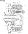
- the auxiliary clutch plate 17 may include a plurality of clutch plates.
- a multiple-plate clutch provided in this case includes a first auxiliary clutch plate 17c and a second auxiliary clutch plate 17d in addition to the auxiliary clutch plate 17 connected to the output shaft 3. Movement of each weight member 10 of the centrifugal clutch means 9 to the radially outer position moves the holding member 11.
- auxiliary clutch plate 17 including a plurality of clutch plates in this manner makes it possible to increase a clutch capacity of the auxiliary clutch plate 17 (which is a multiple-plate clutch including the first auxiliary clutch plate 17c and the second auxiliary clutch plate 17d) to any desired level.
- the auxiliary clutch plate 17 may include a plurality of clutch plates (or may be a multiple-plate clutch including first auxiliary clutch plates 17c and second auxiliary clutch plates 17d) and may overlap, in an axial direction X of the clutch housing 2, with the region where the driving and driven clutch plates 6 and 7 are stacked. Disposing the auxiliary clutch plate 17 such that the auxiliary clutch plate 17 overlaps, in the axial direction X of the clutch housing 2, with the region where the driving and driven clutch plates 6 and 7 are stacked in this manner makes it possible to reliably prevent the apparatus from increasing in size in the axial direction X.
- the auxiliary clutch plate 17 may include a plurality of clutch plates, and the apparatus may include an interlocking member 18 instead of the centrifugal clutch means.
- the auxiliary clutch plate 17 may include a plurality of clutch plates and overlap with the region where the driving and driven clutch plates 6 and 7 are stacked, and the apparatus may include the interlocking member 18 instead of the centrifugal clutch means.
- the auxiliary clutch plate 17 may include a plurality of clutch plates, and the apparatus may include the interlocking member 18 instead of the centrifugal clutch means and may also include a pressing assist cam and a back torque limiter cam.
- disconnection of the second spherical members 15 is prevented by the rolling contact surface (or the groove geometries 11a) of the holding member 11 (or the pressing member 12).
- disconnection of the second spherical members 15 may be prevented by any other disconnection preventing means and method, such as swaging.
- the abutment surface 4ad and the abutment surface 5e are in abutment with each other.
- the first clutch member 4a may include no abutment surface 4ad
- the pressure member 5 may include no abutment surface 5e
- the first clutch member 4a and the pressure member 5 may be located away from each other.
- the power transmission apparatuses according to the present invention may find applications as various multiple-plate clutch type power transmission apparatuses for, for example, motorcycles, automobiles, three-wheel or four-wheel buggies, or general purpose machines.
- a power transmission apparatus includes an auxiliary clutch plate disposed in a clutch housing.
- the auxiliary clutch plate is different in diameter from driving and driven clutch plates.
- the driving and driven clutch plates are pressed against each other, the auxiliary clutch plate is pressed so as to enable transmission of a driving force of an engine to a wheel.
- a pressing force exerted on the driving and driven clutch plates is released, a pressing force exerted on the auxiliary clutch plate is released so as to cut off transmission of the driving force of the engine to the wheel.
- Such a power transmission apparatus may find applications involving, for example, change(s) in external shape or addition of other function(s).
Landscapes
- Engineering & Computer Science (AREA)
- General Engineering & Computer Science (AREA)
- Mechanical Engineering (AREA)
- Chemical & Material Sciences (AREA)
- Combustion & Propulsion (AREA)
- Transportation (AREA)
- One-Way And Automatic Clutches, And Combinations Of Different Clutches (AREA)
- Mechanical Operated Clutches (AREA)
Abstract
Description
- The present invention relates to a power transmission apparatus that is able to freely transmit a rotational force of an input member to an output member or cut off the rotational force.
- Usually, a power transmission apparatus included in a motorcycle freely transmits a driving force of an engine to a transmission and a driving wheel or cuts off the driving force. Such a power transmission apparatus includes: an input member connected to an engine; an output member connected to a transmission and a driving wheel; a clutch member connected to the output member; and a pressure member that is able to move close to or away from the clutch member. Bringing the pressure member close to the clutch member presses driving and driven clutch plates against each other so as to transmit power therebetween. Moving the pressure member away from the clutch member releases a pressing force exerted on the driving and driven clutch plates so as to cut off transmission of the power therebetween.
- As disclosed, for example, in
Patent Literature 1, a power transmission apparatus known in the art includes a centrifugal clutch means including a weight member that moves from a radially inner position of a groove to a radially outer position thereof with centrifugal force produced by rotation of a clutch housing and is thus able to press driving and driven clutch plates against each other. The power transmission apparatus known in the art is able to apply centrifugal force to the weight member in accordance with the rotation of the clutch housing caused by driving of an engine and is thus able to press the driving and driven clutch plates against each other so as to transmit a driving force of the engine to a wheel. - Patent Literature 1:
WO 2013/183588 - Unfortunately, the power transmission apparatus known in the art may require increasing the number of driving clutch plates and the number of driven clutch plates in order to achieve a clutch capacity required for a multiple-plate clutch. In this case, if the required clutch capacity is achieved by simply increasing the number of driving clutch plates and the number of driven clutch plates in a stacking direction of the multiple-plate clutch, the size of the apparatus in an axial direction may increase, which may make the apparatus larger than a space in a vehicle where the apparatus is installable. Such a problem may occur not only in apparatuses including weight members but also in general multiple-plate clutch type power transmission apparatuses including driving and driven clutch plates.
- The present invention has been made in view of the above-described circumstances and its object is to provide a power transmission apparatus that is able to have an increased clutch capacity while being prevented from increasing in size in an axial direction.
- The invention of
claim 1 provides a power transmission apparatus including: a clutch housing that rotates together with an input member that rotates with a driving force of an engine of a vehicle, the clutch housing having a plurality of driving clutch plates attached thereto; a clutch member having a plurality of driven clutch plates attached thereto, the driven clutch plates being arranged alternately with the driving clutch plates attached to the clutch housing, the clutch member being connected to an output member that is able to rotate a wheel of the vehicle; and a pressure member movable between an operating position where the driving and driven clutch plates are pressed against each other so as to enable transmission of the driving force of the engine to the wheel and a non-operating position where a pressing force exerted on the driving and driven clutch plates is released so as to cut off transmission of the driving force of the engine to the wheel. An auxiliary clutch plate different in diameter from the driving and driven clutch plates is disposed in the clutch housing. When the driving and driven clutch plates are pressed against each other, the auxiliary clutch plate is pressed so as to enable transmission of the driving force of the engine to the wheel. When the pressing force exerted on the driving and driven clutch plates is released, a pressing force exerted on the auxiliary clutch plate is released so as to cut off transmission of the driving force of the engine to the wheel. - The invention of
claim 2 is based on the power transmission apparatus according toclaim 1, wherein the power transmission apparatus includes a centrifugal clutch means including a weight member movable from a radially inner position to a radially outer position with centrifugal force produced by rotation of the clutch housing. When the weight member is located at the radially outer position, the centrifugal clutch means presses the auxiliary clutch plate concurrently with pressing the driving and driven clutch plates against each other so as to enable transmission of the driving force of the engine to the wheel. When the weight member is located at the radially inner position, the centrifugal clutch means releases the pressing force exerted on the auxiliary clutch plate concurrently with releasing the pressing force exerted on the driving and driven clutch plates so as to cut off transmission of the driving force of the engine to the wheel. - The invention of
claim 3 is based on the power transmission apparatus according toclaim 2, wherein the centrifugal clutch means includes: a holding member holding the weight member such that the weight member is movable between the radially inner position and the radially outer position; a pressing member to press the driving and driven clutch plates against each other by moving in a stacking direction of the driving and driven clutch plates in response to movement of the weight member from the radially inner position to the radially outer position; and an urging member urging the weight member from the radially outer position to the radially inner position. When the weight member is located at the radially outer position, one of the pressing member and the holding member presses the driving and driven clutch plates against each other, and the other one of the pressing member and the holding member presses the auxiliary clutch plate. - The invention of
claim 4 is based on the power transmission apparatus according to any one ofclaims 1 to 3, wherein the auxiliary clutch plate is disposed such that the auxiliary clutch plate overlaps, in an axial direction of the clutch housing, with a region where the driving and driven clutch plates are stacked. - The invention of
claim 5 is based on the power transmission apparatus according to any one ofclaims 1 to 4, wherein the auxiliary clutch plate includes a plurality of clutch plates. - According to the invention of
claim 1, the auxiliary clutch plate different in diameter from the driving and driven clutch plates is disposed in the clutch housing. When the driving and driven clutch plates are pressed against each other, the auxiliary clutch plate is pressed so as to enable transmission of the driving force of the engine to the wheel. When the pressing force exerted on the driving and driven clutch plates is released, the pressing force exerted on the auxiliary clutch plate is released so as to cut off transmission of the driving force of the engine to the wheel. Consequently, this invention is able to increase a clutch capacity while preventing the apparatus from increasing in size in the axial direction. - According to the invention of
claim 2, the power transmission apparatus includes the centrifugal clutch means configured to, when the weight member is located at the radially outer position, press the auxiliary clutch plate concurrently with pressing the driving and driven clutch plates against each other so as to enable transmission of the driving force of the engine to the wheel, and configured to, when the weight member is located at the radially inner position, release the pressing force exerted on the auxiliary clutch plate concurrently with releasing the pressing force exerted on the driving and driven clutch plates so as to cut off transmission of the driving force of the engine to the wheel. Consequently, with the centrifugal clutch means, this invention is able to press the auxiliary clutch plate or release the pressing force exerted thereon, in addition to pressing the driving and driven clutch plates against each other or releasing the pressing force exerted thereon. - According to the invention of
claim 3, when the weight member is located at the radially outer position, one of the pressing member and the holding member presses the driving and driven clutch plates against each other, and the other one of the pressing member and the holding member presses the auxiliary clutch plate. Consequently, with the pressing member and the holding member included in the centrifugal clutch means, this invention is able to press the auxiliary clutch plate or release the pressing force exerted thereon, in addition to pressing the driving and driven clutch plates against each other or releasing the pressing force exerted thereon. - According to the invention of
claim 4, the auxiliary clutch plate is disposed such that the auxiliary clutch plate overlaps, in the axial direction of the clutch housing, with the region where the driving and driven clutch plates are stacked. Consequently, this invention is able to reliably prevent the apparatus from increasing in size in the axial direction. - According to the invention of
claim 5, the auxiliary clutch plate includes a plurality of clutch plates. Consequently, this invention is able to increase a clutch capacity of the auxiliary clutch plate to any desired level. -
-
FIG. 1 is an external view of a power transmission apparatus according to an embodiment of the present invention. -
FIG. 2 is a cross-sectional view taken along the line II-II inFIG. 1 . -
FIG. 3 is a cross-sectional view taken along the line III-III inFIG. 1 . -
FIG. 4 is a perspective view of a clutch housing of the power transmission apparatus. -
FIG. 5 is a three-view drawing of a first clutch member of the power transmission apparatus. -
FIG. 6 is a perspective view of the first clutch member. -
FIG. 7 is a three-view drawing of a second clutch member of the power transmission apparatus. -
FIG. 8 is a perspective view of the second clutch member. -
FIG. 9 is a three-view drawing of a pressure member of the power transmission apparatus. -
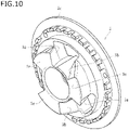
FIG. 10 is a perspective view of the pressure member. -
FIG. 11 is a longitudinal cross-sectional view of a centrifugal clutch means of the power transmission apparatus. -
FIG. 12 is a partially cutaway perspective view of the centrifugal clutch means. -
FIG. 13 is a three-view drawing of a holding member included in the centrifugal clutch means. -
FIG. 14 is a three-view drawing of a supporting member included in the centrifugal clutch means. -
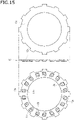
FIG. 15 is a three-view drawing of a pressing member included in the centrifugal clutch means. -
FIG. 16 is a four-view drawing of a weight member included in the centrifugal clutch means. -
FIG. 17 is a cross-sectional view taken along the line XVII-XVII inFIG. 16 . -
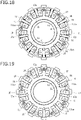
FIG. 18 is a plan view illustrating a state of the centrifugal clutch means where each weight member is located at a radially inner position. -
FIG. 19 is a plan view illustrating a state of the centrifugal clutch means where each weight member is located at a radially outer position. -
FIG. 20a is a schematic diagram describing how a pressing assist cam of the power transmission apparatus acts. -
FIG. 20b is a schematic diagram describing how a back torque limiter cam of the power transmission apparatus acts. -
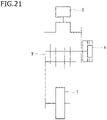
FIG. 21 is a schematic diagram of a vehicle in which the power transmission apparatus is used. -
FIG. 22 is a cross-sectional view illustrating a state of the power transmission apparatus where each weight member is located at the radially inner position. -
FIG. 23 is a cross-sectional view illustrating a state of the power transmission apparatus where each weight member is located at an intermediate position between the radially inner position and the radially outer position. -
FIG. 24 is a cross-sectional view illustrating a state of the power transmission apparatus where each weight member is located at the radially outer position. -
FIG. 25 is a cross-sectional view illustrating a state of the power transmission apparatus where each weight member is located at the radially outer position and the pressure member is located at a non-operating position. -
FIG. 26 is a longitudinal cross-sectional view of a power transmission apparatus according to another embodiment of the present invention (in which an auxiliary clutch plate includes a plurality of clutch plates). -
FIG. 27 is a longitudinal cross-sectional view of a power transmission apparatus according to still another embodiment of the present invention (in which an auxiliary clutch plate includes a plurality of clutch plates and overlaps with a region where driving and driven clutch plates are stacked). -
FIG. 28 is a longitudinal cross-sectional view of a power transmission apparatus according to yet another embodiment of the present invention (in which an auxiliary clutch plate includes a plurality of clutch plates, and the apparatus includes no centrifugal clutch means). -
FIG. 29 is a longitudinal cross-sectional view of a power transmission apparatus according to still yet another embodiment of the present invention (in which an auxiliary clutch plate includes a plurality of clutch plates and overlaps with a region where driving and driven clutch plates are stacked, and the apparatus includes no centrifugal clutch means). -
FIG. 30 is a longitudinal cross-sectional view of a power transmission apparatus according to another embodiment of the present invention (in which an auxiliary clutch plate includes a plurality of clutch plates, and the apparatus includes no centrifugal clutch means but includes a pressing assist cam and a back torque limiter cam). - Embodiments of the present invention will be described below in detail with reference to the drawings. As illustrated in
FIG. 21 , a power transmission apparatus K according to the present embodiment is disposed in a vehicle so as to freely transmit a driving force of an engine E to a driving wheel T through a transmission M or cut off the driving force. As illustrated inFIGS. 1 to 17 , the power transmission apparatus K includes: aclutch housing 2 provided with an input gear 1 (which is an input member) that rotates with the driving force of the engine E of the vehicle; an output shaft 3 (which is an output member) connected to the transmission M; a clutch member (which includes a firstclutch member 4a and a secondclutch member 4b); apressure member 5; a plurality of drivingclutch plates 6; a plurality of drivenclutch plates 7; a centrifugal clutch means 9 includingweight members 10; and an auxiliaryclutch plate 17. - The
input gear 1 is rotatable around theoutput shaft 3 upon receiving a driving force (or a rotational force) transmitted from the engine E. Theinput gear 1 is connected to theclutch housing 2 with a fastener, such as a rivet. Theclutch housing 2 is a cylindrical member with an opening defined at its right end inFIGS. 2 and3 and is connected to theinput gear 1. Theclutch housing 2 is rotatable together with rotation of theinput gear 1 with the driving force of the engine E. - As illustrated in
FIG. 4 , theclutch housing 2 is circumferentially provided with a plurality of cut-outs 2a. The drivingclutch plates 6 are fitted to the cut-outs 2A and thus attached to theclutch housing 2. The drivingclutch plates 6 are each made of a substantially annular plate material. The drivingclutch plates 6 are rotatable together with rotation of theclutch housing 2. The drivingclutch plates 6 are slidable in an axial direction (which corresponds to a right-left direction inFIGS. 2 and3 ). - The driven
clutch plates 7 are attached to the clutch member (which includes the firstclutch member 4a and the secondclutch member 4b). The drivenclutch plates 7 are arranged alternately with the drivingclutch plates 6 attached to theclutch housing 2. The clutch member is connected to the output shaft 3 (i.e., the output member) that is able to rotate the driving wheel T through the transmission M of the vehicle. The clutch member is provided by assembling two members, i.e., the firstclutch member 4a and the secondclutch member 4b, to each other. - The
output shaft 3 is inserted through an insertion hole (seeFIGS. 5 and6 ) defined in the center of the firstclutch member 4a. A gear provided on the firstclutch member 4a and a gear provided on theoutput shaft 3 mesh with each other so as to be connected to each other in the direction of rotation. As illustrated inFIGS. 5 and6 , the firstclutch member 4a is provided with: inclined surfaces 4aa each defining a pressing assist cam; and inclined surfaces 4ab each defining a back torque limiter cam. The reference signs "4ac" inFIGS. 5 and6 each indicate a boss provided with an insertion hole for a bolt B for connection between the firstclutch member 4a and a securingmember 8. - As illustrated in
FIGS. 7 and8 , the secondclutch member 4b is an annular member provided with a flange 4bb. The drivenclutch plates 7 are spline-fitted to a spline-fitting portion 4ba provided on the outer peripheral surface of the secondclutch member 4b and are thus attached to the secondclutch member 4b. As illustrated inFIGS. 2 and3 , thepressure member 5 is assembled to the clutch member (which includes the firstclutch member 4a and the secondclutch member 4b) such that the driving and drivenclutch plates flange 5c of thepressure member 5 and the flange 4bb of the secondclutch member 4b. - As illustrated in
FIGS. 9 and10 , thepressure member 5 is a disk member provided with theflange 5c extending along the peripheral edge of thepressure member 5. Thepressure member 5 is movable between: an operating position where the driving and drivenclutch plates clutch plates - More specifically, as illustrated in
FIGS. 7 and8 , the spline-fitting portion 4ba provided on the secondclutch member 4b forms integral projections and depressions along substantially the entire outer peripheral side surface of the secondclutch member 4b. Fitting the drivenclutch plates 7 to recessed grooves that define the spline-fitting portion 4ba restricts movement of the drivenclutch plates 7 in the direction of rotation while allowing movement of the drivenclutch plates 7 in the axial direction relative to the secondclutch member 4b. The drivenclutch plates 7 are rotatable together with the secondclutch member 4b. - The driven
clutch plates 7 are stacked alternately with the drivingclutch plates 6, making it possible to allow theclutch plates clutch plates clutch member 4b. Engaging a clutch by pressing the clutch plates (6a, 6b, 7a, 7b) against each other enables a rotational force of theclutch housing 2 to be transmitted to theoutput shaft 3 through the secondclutch member 4b and the firstclutch member 4a. Disengaging the clutch by releasing the pressing force exerted on the clutch plates (6a, 6b, 7a, 7b) causes the firstclutch member 4a and the secondclutch member 4b to stop following the rotation of theclutch housing 2 such that no rotational force will be transmitted to theoutput shaft 3. - Accordingly, a state where the driving and driven
clutch plates clutch housing 2, to the driving wheel (or the transmission M) through the output shaft 3 (i.e., the output member), and a state where the driving and drivenclutch plates clutch housing 2, to the output shaft 3 (i.e., the output member). - As illustrated in
FIGS. 9 and10 , thepressure member 5 is circumferentially provided with a plurality offitting holes 5d (i.e., threefitting holes 5d in the present embodiment). A clutch spring S is fitted into each of thefitting holes 5d. As illustrated inFIG. 2 , one end of each clutch spring S housed in the associatedfitting hole 5d is in abutment with the securingmember 8, such that each clutch spring S urges thepressure member 5 in a direction in which the driving and drivenclutch plates clutch plates clutch plates - In the present embodiment, as illustrated in
FIGS. 5 ,6 ,9 , and10 , the firstclutch member 4a is provided with the inclined surfaces 4aa and 4ab, and thepressure member 5 is provided withinclined surfaces inclined surface 5a so as to provide the pressing assist cam, and each inclined surface 4ab comes into abutment with the associatedinclined surface 5b so as to provide the back torque limiter cam. - Suppose that the rotation speed of the engine E is increased and the resulting rotational force received by the
input gear 1 and theclutch housing 2 is transmittable to theoutput shaft 3 through the firstclutch member 4a and the secondclutch member 4b (which means that theweight members 10 are each located at a radially outer position). In this case, as illustrated inFIG. 20a , the rotational force is applied to thepressure member 5 in an a-direction, which exerts a force on thepressure member 5 in a c-direction inFIG. 20a under the action of each pressing assist cam. Thepressure member 5 is thus moved in a direction in which itsflange 5c comes closer to the flange 4bb of the secondclutch member 4b (i.e., leftward inFIGS. 2 and3 ) so as to increase the pressing force exerted on the driving and drivenclutch plates - Suppose that the rotation of the
output shaft 3 exceeds the rotation speed of theinput gear 1 and theclutch housing 2, resulting in a back torque. In this case, as illustrated inFIG. 20b , a rotational force is applied to theclutch member 4 in a b-direction, which moves thepressure member 5 in a d-direction inFIG. 20b under the action of each back torque limiter cam so as to release the pressing force exerted on the driving and drivenclutch plates - As illustrated in
FIGS. 11 to 19 , the centrifugal clutch means 9 includes theweight members 10 each movable from a radially inner position (seeFIG. 18 ) to the radially outer position (seeFIG. 19 ) with centrifugal force produced by rotation of theclutch housing 2. When theweight members 10 are each located at the radially outer position, the centrifugal clutch means 9 presses the driving and drivenclutch plates weight members 10 are each located at the radially inner position, the centrifugal clutch means 9 releases the pressing force exerted on the driving and drivenclutch plates - Specifically, the centrifugal clutch means 9 includes: the
weight members 10, each of which is a substantially symmetrical polygonal member; a holdingmember 11 having a supportingmember 13 attached thereto; a pressingmember 12; firstspherical members 14; secondspherical members 15; and urgingmembers 16, each of which is a coil spring. The holdingmember 11 and the pressingmember 12 are each circumferentially provided with a plurality of protrusions. Similarly to the drivingclutch plates 6, the protrusions are fitted to the cut-outs 2a of theclutch housing 2 such that the holdingmember 11 and the pressingmember 12 are attached to theclutch housing 2. Accordingly, the holdingmember 11 and the pressingmember 12 are each movable in the axial direction of theclutch housing 2 and in engagement with theclutch housing 2 in the direction of rotation so as to be rotatable together with theclutch housing 2. - As illustrated in
FIG. 16 , eachweight member 10 is a substantially symmetrical polygonal member including a first surface X and a second surface Y. As illustrated inFIGS. 16 and 17 , eachweight member 10 includes: throughholes 10a passing through theweight member 10 from the first surface X to the second surface Y;insertion portions 10b defined in the second surface Y; and agroove 10c defined in the first surface X. As illustrated inFIGS. 18 and 19 , theweight members 10 are each housed in an associated one ofhousing portions 11a of the holdingmember 11. When no centrifugal force is applied to theweight members 10, theweight members 10 are each held at the radially inner position (seeFIG. 18 ). Application of centrifugal force to theweight members 10 moves theweight members 10 outward against the urging force of the urgingmembers 16 such that eachweight member 10 reaches the radially outer position (seeFIG. 19 ). - The holding
member 11 holds theweight members 10 such that eachweight member 10 is movable between the radially inner position and the radially outer position. As illustrated inFIG. 13 , the holdingmember 11 is an annular member. The holdingmember 11 includes: thehousing portions 11a which are arranged in the circumferential direction of the holdingmember 11 and in which theweight members 10 are to be housed;groove geometries 11b defined in thehousing portions 11a; and a pushingsurface 11c. Eachhousing portion 11a has a recessed shape conforming to the shape and moving range of the associatedweight member 10. An inner peripheral wall surface 11aa of eachhousing portion 11a is allowed to abut against first ends of the associated urgingmembers 16. - The supporting
member 13 is secured to a surface of the holdingmember 11, which is provided with thehousing portions 11a. As illustrated inFIG. 14 , the supportingmember 13 is provided with radially extending holdingportions 13a. The holdingportions 13a each conform to thegroove 10c of the associatedweight member 10, so that theweight members 10 are held by the holdingmember 11. Specifically, the first surface X of eachweight member 10 is centrally provided with thegroove 10c extending in a direction from the radially inner position to the radially outer position. Causing each holdingportion 13a to conform to the associatedgroove 10c allows the holdingmember 11 to hold theweight members 10 such that eachweight member 10 is movable in a radial direction (i.e., in a direction from the radially inner position to the radially outer position). - Movement of each
weight member 10 from the radially inner position to the radially outer position causes the pressingmember 12 to move in a stacking direction of the driving and drivenclutch plates 6 and 7 (i.e., rightward inFIGS. 2 and3 ) such that the driving and drivenclutch plates FIG. 15 , the pressingmember 12 is an annular member. The pressingmember 12 includes:inclined grooves 12a arranged in the circumferential direction of the pressingmember 12;groove geometries 12b each defined at a position where the associatedinclined groove 12a is defined; and a pushingsurface 12c. - Each
inclined groove 12a is defined at a position corresponding to the position of the associatedweight member 10. Eachinclined groove 12a is inclined upward from its inner portion to its outer portion. Thus, when theclutch housing 2 is stationary, eachweight member 10 is held at the radially inner position with the urging force of the associated urgingmembers 16. Rotation of theclutch housing 2 applies centrifugal force to theweight members 10 so as to move theweight members 10 along theinclined grooves 12a inclined upward. This moves the pressingmember 12 away from the holding member 11 (i.e., in the direction in which the driving and drivenclutch plates - When the holding
member 11 and the pressingmember 12 are assembled to each other, with theweight members 10 interposed therebetween, eachinclined groove 12a is located at a position corresponding to the position of the associatedweight member 10 as illustrated inFIGS. 11 and 12 . With centrifugal force, theweight members 10 each move along theinclined grooves 12a from the radially inner position to the radially outer position, which moves the pressingmember 12 in a direction indicated by the arrow inFIG. 11 (i.e., rightward inFIG. 11 ). The pushingsurface 12c of the pressingmember 12 thus pushes the driving and drivenclutch plates clutch plates member 11 in a direction opposite to the direction indicated by the arrow inFIG. 11 (i.e., leftward inFIG. 11 ), so that the pushingsurface 11c of the holdingmember 11 presses the auxiliaryclutch plate 17. - As illustrated in
FIGS. 18 and 19 , theweight members 10 according to the present embodiment are each housed in an associated one of thehousing portions 11a arranged in the circumferential direction of the holdingmember 11 such that theweight members 10 are movable radially. More than one urging member 16 (i.e., two urgingmembers 16 in the present embodiment) is disposed in the circumferential direction between the inner peripheral wall surface 11aa (seeFIG. 13 ) of each of thehousing portions 11a and an associated one of theweight members 10 so as to urge the associatedweight member 10 from the radially outer position to the radially inner position. In this embodiment, the inner peripheral wall surface 11aa of eachhousing portion 11a is a flat surface in abutment with the first ends of the associated urgingmembers 16 such that the urgingmembers 16 are stably securable. - The
weight members 10 according to the present embodiment are each provided with the tunnel-shapedinsertion portions 10b which are openings defined in a surface of eachweight member 10 facing the holding member 11 (i.e., the second surface Y inFIG. 17 ) and into which the urgingmembers 16 are inserted such that the urgingmembers 16 are attachable to the associatedweight member 10. Theweight members 10, with the urgingmembers 16 inserted into theinsertion portions 10b, are housed in thehousing portions 11a of the holdingmember 11. The urgingmembers 16 are thus secured such that each urgingmember 16 is interposed between the inner peripheral wall surface 11aa of the associatedhousing portion 11a and the associatedweight member 10. The urgingmembers 16 are disposed such that the first end of each urgingmember 16 is in abutment with the associated inner peripheral wall surface 11aa and a second end of each urgingmember 16 is in abutment with an end wall surface 10ba of the associatedinsertion portion 10b, making it possible to urge eachweight member 10 from the radially outer position to the radially inner position. - Each first
spherical member 14 is a steel ball attached to the associatedweight member 10. As illustrated inFIGS. 16 and 17 , each firstspherical member 14 is partially protruded from a first opening 10aa (i.e., a small-diameter opening in the first surface X) of the throughhole 10a defined in the associatedweight member 10 and is in contact with a rolling contact surface of the pressingmember 12 so as to be rollable thereon. Each secondspherical member 15 is a steel ball attached to the associatedweight member 10. As illustrated inFIGS. 16 and 17 , each secondspherical member 15 is partially protruded from a second opening 10ab (i.e., a large-diameter opening in the second surface Y) of the throughhole 10a defined in the associatedweight member 10 and is in contact with a rolling contact surface of the holdingmember 11 so as to be rollable thereon. - As illustrated in
FIG. 17 , the throughholes 10a according to the present embodiment are tapered such that the diameter of each throughhole 10a continuously increases from the first opening 10aa (i.e., the small-diameter opening in the first surface X) to the second opening 10ab (i.e., the large-diameter opening in the second surface Y). Disconnection of each firstspherical member 14 from the associated throughhole 10a is prevented by the outer peripheral edge of one of the first opening 10aa and the second opening 10ab that has a smaller diameter (which is, in the present embodiment, the first opening 10aa in the first surface X). The first and secondspherical members holes 10a. The secondspherical members 15 are larger in diameter than the firstspherical members 14. The small-diameter firstspherical members 14 are each rollable while being in contact with the inner peripheral surface of the associated throughhole 10a, and at the same time, disconnection of the small-diameter firstspherical members 14 is prevented by the small-diameter opening edges of the throughholes 10a. - As illustrated in
FIGS. 11 and 12 , disconnection of the secondspherical members 15 is prevented by the rolling contact surface of the holdingmember 11. Thus, disconnection of the small-diameter firstspherical members 14 is prevented by the small-diameter opening edges of the throughholes 10a, and disconnection of the large-diameter secondspherical members 15 is prevented by the rolling contact surface of the holdingmember 11 while the secondspherical members 15 are partially protruded from the large-diameter openings of the throughholes 10a. In the present embodiment, the large-diameter secondspherical members 15 are assembled to theweight members 10 such that the secondspherical members 15 face the rolling contact surface of the holdingmember 11. Alternatively, the secondspherical members 15 may be assembled to theweight members 10 such that the secondspherical members 15 face the rolling contact surface of the pressingmember 12. In this case, disconnection of the small-diameter firstspherical members 14 is prevented by the small-diameter opening edges of the throughholes 10a, and disconnection of the large-diameter secondspherical members 15 is prevented by the rolling contact surface of the pressingmember 12 while the secondspherical members 15 are partially protruded from the large-diameter openings of the throughholes 10a. - As illustrated in
FIG. 13 , the rolling contact surface of the holding member 11 (which is, in the present embodiment, a surface of the holdingmember 11 on which the secondspherical members 15 roll) includes thegroove geometries 11b each extending in the direction of movement of the associated weight member 10 (i.e., a direction connecting the radially inner position to the radially outer position). As illustrated inFIG. 15 , the rolling contact surface of the pressing member 12 (which is, in the present embodiment, a surface of the pressingmember 12 on which the firstspherical members 14 roll) includes thegroove geometries 12b each extending in the direction of movement of the associated weight member 10 (i.e., a direction connecting the radially inner position to the radially outer position). - As illustrated in
FIGS. 16 ,18, and 19 , the first and secondspherical members spherical member 14 and more than one secondspherical member 15 are arranged in the circumferential direction of the holding member 11 (i.e., such that two firstspherical members 14 and two secondspherical members 15 are arranged in the width direction of eachweight member 10 in the present embodiment). In response to movement of theweight members 10, the firstspherical members 14 are movable along thegroove geometries 12b while rolling within the throughholes 10a, and the secondspherical members 15 are movable along thegroove geometries 11b while rolling within the throughholes 10a. - The auxiliary
clutch plate 17 is disposed in theclutch housing 2. The auxiliaryclutch plate 17 is an annular member different in diameter from the driving and drivenclutch plates 6 and 7 (i.e., smaller in diameter than the driving and drivenclutch plates FIGS. 2 and3 , the output shaft 3 (i.e., the output member) is inserted through acentral opening 17a of the auxiliaryclutch plate 17 so as to be fitted thereto. The auxiliaryclutch plate 17 includes a pushedsurface 17b facing the pushingsurface 11c of the holdingmember 11. - When the
weight members 10 are each located at the radially outer position (i.e., when the driving and drivenclutch plates clutch plate 17 is able to transmit the driving force of the engine E to theoutput shaft 3 upon being pushed by the pushingsurface 11c of the holdingmember 11 and pressed against the pushingsurface 11c. When theweight members 10 are each located at the radially inner position (i.e., when the pressing force exerted on the driving and drivenclutch plates clutch plate 17 is able to cut off transmission of the driving force of the engine E to theoutput shaft 3 upon being relieved of a pressing force applied thereto, owing to a decrease in pushing force exerted by the pushingsurface 11c of the holdingmember 11. - Upon movement of each
weight member 10 to the radially outer position, eachinclined groove 12a functions as a cam so as to cause the holdingmember 11 and the pressingmember 12 to move away from each other. Accordingly, the pushingsurface 12c of the pressingmember 12 presses the driving and drivenclutch plates surface 11c of the holdingmember 11 pushes the pushedsurface 17b of the auxiliaryclutch plate 17 such that the pushedsurface 17b is pressed against the pushingsurface 11c so as to transmit the driving force of the engine E to the driving wheel T. - As illustrated in
FIGS. 5 and6 , a portion of a surface of the firstclutch member 4a according to the present embodiment, which faces thepressure member 5, defines an abutment surface 4ad. As illustrated inFIGS. 9 and10 , a portion of a surface of thepressure member 5, which faces the firstclutch member 4a, defines anabutment surface 5e. With the firstclutch member 4a, the secondclutch member 4b, and thepressure member 5 assembled to each other (and with no torque being transmitted from the input gear 1 (i.e., the input member) to the output shaft 3 (i.e., the output member)), the abutment surface 4ad and theabutment surface 5e are in abutment with each other as illustrated inFIGS. 2 and3 . - With the abutment surface 4ad and the
abutment surface 5e in abutment with each other as mentioned above, in the course of movement of eachweight member 10 of the centrifugal clutch means 9 from the radially inner position (seeFIG. 22 ) to an intermediate position (seeFIG. 23 ) and a resulting increase in torque transmitted from the input gear 1 (i.e., the input member) to the output shaft 3 (i.e., the output member), the firstclutch member 4a and thepressure member 5 are not allowed to move relative to each other, which restricts operation of the pressing assist cams. - Each
weight member 10 of the centrifugal clutch means 9 then further moves from the intermediate position (seeFIG. 23 ) to the radially outer position (seeFIG. 24 ), and the driving and drivenclutch plates clutch member 4b and thus pressed against each other. When the pushing force of the flange 4bb is equal to or greater than the urging force of the clutch springs S, the secondclutch member 4b and thepressure member 5 are moved in the axial direction (i.e., rightward inFIGS. 2 and3 ) relative to the firstclutch member 4a, so that the abutment surface 4ad of the firstclutch member 4a and theabutment surface 5e of thepressure member 5 are located away from each other.FIG. 25 illustrates a state in which theweight members 10 are each located at the radially outer position and thepressure member 5 is located at the non-operating position (i.e., a clutch-disengaged state). - With the abutment surface 4ad and the
abutment surface 5e located away from each other as mentioned above, in the course of movement of eachweight member 10 of the centrifugal clutch means 9 from the radially inner position to the radially outer position and a resulting increase in torque transmitted from the input gear 1 (i.e., the input member) to the output shaft 3 (i.e., the output member), the firstclutch member 4a and thepressure member 5 are allowed to move relative to each other, which allows operation of the pressing assist cams. - In the present embodiment, when the driving and driven
clutch plates clutch plate 17 is pressed so as to enable transmission of the driving force of the engine E to the wheel (i.e., the driving wheel T). When the pressing force exerted on the driving and drivenclutch plates clutch plate 17 is released so as to cut off transmission of the driving force of the engine E to the wheel (i.e., the driving wheel T). - More specifically, the present embodiment involves providing the centrifugal clutch means 9 including the
weight members 10. When theweight members 10 are each located at the radially outer position, the centrifugal clutch means 9 presses the auxiliaryclutch plate 17 concurrently with pressing the driving and drivenclutch plates weight members 10 are each located at the radially inner position, the centrifugal clutch means 9 releases the pressing force exerted on the auxiliaryclutch plate 17 concurrently with releasing the pressing force exerted on the driving and drivenclutch plates - In the present embodiment, in particular, when the
weight members 10 are each located at the radially outer position, the pressingmember 12 and the holdingmember 11 move away from each other, the pressingmember 12 presses the driving and drivenclutch plates member 11 presses the auxiliaryclutch plate 17. Alternatively, the centrifugal clutch means 9 may be disposed such that when theweight members 10 are each located at the radially outer position, the pressingmember 12 and the holdingmember 11 move away from each other, the holdingmember 11 presses the driving and drivenclutch plates member 12 presses the auxiliaryclutch plate 17. - In the present embodiment, the auxiliary
clutch plate 17 different in diameter from the driving and drivenclutch plates clutch housing 2. When the driving and drivenclutch plates clutch plate 17 is pressed so as to enable transmission of the driving force of the engine E to the wheel (i.e., the driving wheel T). When the pressing force exerted on the driving and drivenclutch plates clutch plate 17 is released so as to cut off transmission of the driving force of the engine E to the wheel (i.e., the driving wheel T). Accordingly, the present embodiment is able to increase a clutch capacity while preventing the apparatus from increasing in size in the axial direction. - The auxiliary
clutch plate 17 according to the present embodiment, in particular, is disposed radially inward of a region where the driving and drivenclutch plates clutch housing 2. Accordingly, the present embodiment is able to increase a clutch capacity while preventing the apparatus from increasing in size not only in the axial direction but also in a direction perpendicular to the axial direction, and to effectively utilize a radially inner space inside theclutch housing 2. - The present embodiment involves providing the centrifugal clutch means 9 configured to, when the
weight members 10 are each located at the radially outer position, press the auxiliaryclutch plate 17 concurrently with pressing the driving and drivenclutch plates weight members 10 are each located at the radially inner position, release the pressing force exerted on the auxiliaryclutch plate 17 concurrently with releasing the pressing force exerted on the driving and drivenclutch plates clutch plate 17 or release the pressing force exerted thereon, in addition to pressing the driving and drivenclutch plates - When the
weight members 10 are each located at the radially outer position, one of the pressingmember 12 and the holdingmember 11 presses the driving and drivenclutch plates member 12 and the holdingmember 11 presses the auxiliaryclutch plate 17. Accordingly, with the pressingmember 12 and the holdingmember 11 included in the centrifugal clutch means 9, the present embodiment is able to press the auxiliaryclutch plate 17 or release the pressing force exerted thereon, in addition to pressing the driving and drivenclutch plates - In the power transmission apparatus K according to the present embodiment, the through
holes 10a of theweight members 10 included in the centrifugal clutch means 9 each have a tapered shape from the first opening 10aa to the second opening 10ab. Disconnection of each firstspherical member 14 is prevented by the outer peripheral edge of one of the associated first opening 10aa and the associated second opening 10ab that has a smaller diameter. Accordingly, the present embodiment is able to easily and accurately attach the firstspherical members 14 to theweight members 10, resulting in a reduction in manufacturing cost. - The first and second
spherical members holes 10a. The first and secondspherical members holes 10a. Thus, during movement of theweight members 10, the first and secondspherical members weight members 10 move smoothly. Disconnection of the secondspherical members 15 according to the present embodiment is prevented by the rolling contact surface of the holdingmember 11 or the pressingmember 12. Consequently, assembling the holdingmember 11 and the pressingmember 12 to each other facilitates preventing disconnection of the first and secondspherical members - The rolling contact surface of the holding
member 11 or the pressingmember 12 includes the groove geometries (11b, 12b) extending in the direction of movement of theweight members 10. Accordingly, the present embodiment enables smoother movement of theweight members 10 while reliably preventing disconnection of the secondspherical members 15 from the large-diameter openings and disconnection of the firstspherical members 14 from the small-diameter openings. - In addition, the
weight members 10 according to the present embodiment are each housed in an associated one of thehousing portions 11a arranged in the circumferential direction of the holdingmember 11 and are thus movable radially. More than one urgingmember 16 is disposed in the circumferential direction between the inner peripheral wall surface 11aa of each of thehousing portions 11a and an associated one of theweight members 10 so as to urge the associatedweight member 10 from the radially outer position to the radially inner position. Accordingly, the present embodiment is able to accurately urge eachweight member 10 from the radially outer position to the radially inner position, enabling stable movement of theweight members 10 in accordance with centrifugal force. - The
weight members 10 according to the present embodiment are each provided with theinsertion portions 10b which are openings defined in the surface of eachweight member 10 facing the holdingmember 11 and into which the urgingmembers 16 are inserted such that the urgingmembers 16 are attachable to the associatedweight member 10. This facilitates assembling the urgingmembers 16 to theweight members 10. Theweight members 10 according to the present embodiment are each provided with thegroove 10c extending in a direction from the radially inner position to the radially outer position. The holding member 11 (or specifically, the supportingmember 13 secured to the holdingmember 11 so as to be integral therewith) is provided with the holdingportions 13a each conforming to the associatedgroove 10c and holding the associatedweight member 10. Accordingly, the present embodiment enables stable movement of theweight members 10. - The centrifugal clutch means 9 according to the present embodiment includes: the first
spherical members 14 that are partially protruded from the first openings 10aa of the throughholes 10a defined in theweight members 10 and are in contact with the rolling contact surface (or thegroove geometries 11b) of the holdingmember 11 so as to be rollable thereon; and the secondspherical members 15 that are partially protruded from the second openings 10ab of the throughholes 10a defined in theweight members 10 and are in contact with the rolling contact surface (or thegroove geometries 12b) of the pressingmember 12 so as to be rollable thereon. Accordingly, the present embodiment enables more stable movement of theweight members 10. - The holding
member 11 or the pressingmember 12, in particular, includes the groove geometries (11b, 12b) extending in the direction of movement of theweight members 10. The groove geometries (11b, 12b) define the rolling contact surface for the firstspherical members 14 or the secondspherical members 15 so as to enable smoother movement of theweight members 10. The first and secondspherical members spherical member 14 and more than one secondspherical member 15 are arranged in the circumferential direction of the holding member 11 (i.e., the width direction of each weight member 10). Accordingly, the present embodiment enables more stable movement of theweight members 10. - Although the present embodiment has been described thus far, the present invention is not limited to this embodiment. As illustrated in
FIG. 26 , for example, the auxiliaryclutch plate 17 may include a plurality of clutch plates. A multiple-plate clutch provided in this case includes a first auxiliaryclutch plate 17c and a second auxiliaryclutch plate 17d in addition to the auxiliaryclutch plate 17 connected to theoutput shaft 3. Movement of eachweight member 10 of the centrifugal clutch means 9 to the radially outer position moves the holdingmember 11. This causes the pushingsurface 11c of the holdingmember 11 to push the second auxiliaryclutch plate 17d such that the auxiliaryclutch plate 17, the first auxiliaryclutch plate 17c, and the second auxiliaryclutch plate 17d are pressed against each other, enabling transmission of the driving force of the engine E to the wheel (i.e., the driving wheel T). Providing the auxiliaryclutch plate 17 including a plurality of clutch plates in this manner makes it possible to increase a clutch capacity of the auxiliary clutch plate 17 (which is a multiple-plate clutch including the first auxiliaryclutch plate 17c and the second auxiliaryclutch plate 17d) to any desired level. - As illustrated in
FIG. 27 , the auxiliaryclutch plate 17 may include a plurality of clutch plates (or may be a multiple-plate clutch including first auxiliaryclutch plates 17c and second auxiliaryclutch plates 17d) and may overlap, in an axial direction X of theclutch housing 2, with the region where the driving and drivenclutch plates clutch plate 17 such that the auxiliaryclutch plate 17 overlaps, in the axial direction X of theclutch housing 2, with the region where the driving and drivenclutch plates - As illustrated in
FIG. 28 , the auxiliaryclutch plate 17 may include a plurality of clutch plates, and the apparatus may include an interlockingmember 18 instead of the centrifugal clutch means. As illustrated inFIG. 29 , the auxiliaryclutch plate 17 may include a plurality of clutch plates and overlap with the region where the driving and drivenclutch plates member 18 instead of the centrifugal clutch means. As illustrated inFIG. 30 , the auxiliaryclutch plate 17 may include a plurality of clutch plates, and the apparatus may include the interlockingmember 18 instead of the centrifugal clutch means and may also include a pressing assist cam and a back torque limiter cam. When thepressure member 5 is moved such that the driving and drivenclutch plates member 18 toward the auxiliaryclutch plate 17 such that the interlockingmember 18 presses the auxiliaryclutch plate 17. - In the present embodiment, disconnection of the second
spherical members 15 is prevented by the rolling contact surface (or thegroove geometries 11a) of the holding member 11 (or the pressing member 12). Alternatively, disconnection of the secondspherical members 15 may be prevented by any other disconnection preventing means and method, such as swaging. In the present embodiment, with the firstclutch member 4a, the secondclutch member 4b, and thepressure member 5 assembled to each other (and with no torque being transmitted from the input gear 1 (i.e., the input member) to the output shaft 3 (i.e., the output member)), the abutment surface 4ad and theabutment surface 5e are in abutment with each other. Alternatively, the firstclutch member 4a may include no abutment surface 4ad, thepressure member 5 may include noabutment surface 5e, and the firstclutch member 4a and thepressure member 5 may be located away from each other. The power transmission apparatuses according to the present invention may find applications as various multiple-plate clutch type power transmission apparatuses for, for example, motorcycles, automobiles, three-wheel or four-wheel buggies, or general purpose machines. - A power transmission apparatus includes an auxiliary clutch plate disposed in a clutch housing. The auxiliary clutch plate is different in diameter from driving and driven clutch plates. When the driving and driven clutch plates are pressed against each other, the auxiliary clutch plate is pressed so as to enable transmission of a driving force of an engine to a wheel. When a pressing force exerted on the driving and driven clutch plates is released, a pressing force exerted on the auxiliary clutch plate is released so as to cut off transmission of the driving force of the engine to the wheel. Such a power transmission apparatus may find applications involving, for example, change(s) in external shape or addition of other function(s).
-
- 1
- input gear (input member)
- 2
- clutch housing
- 2a
- cut-out
- 3
- output shaft (output member)
- 4a
- first clutch member
- 4aa
- inclined surface (pressing assist cam)
- 4ab
- inclined surface (back torque limiter cam)
- 4ac
- boss
- 4ad
- abutment surface
- 4b
- second clutch member
- 4ba
- spline-fitting portion
- 4bb
- flange
- 5
- pressure member
- 5a
- inclined surface (pressing assist cam)
- 5b
- inclined surface (back torque limiter cam)
- 5c
- flange
- 5d
- fitting hole
- 5e
- abutment surface
- 6
- driving clutch plate
- 7
- driven clutch plate
- 8
- securing member
- 9
- centrifugal clutch means
- 10
- weight member
- 10a
- through hole
- 10b
- insertion portion
- 10aa
- first opening
- 10ab
- second opening
- 10ba
- end wall surface
- 10c
- groove
- 11
- holding member
- 11a
- housing portion
- 11aa
- inner peripheral wall surface
- 11b
- groove geometry
- 11c
- pushing surface
- 12
- pressing member
- 12a
- inclined groove
- 12b
- groove geometry
- 12c
- pushing surface
- 13
- supporting member
- 13a
- holding portion
- 14
- first spherical member
- 15
- second spherical member
- 16
- urging member
- 17
- auxiliary clutch plate
- 17a
- central opening
- 17b
- pushed surface
- 17c
- first auxiliary clutch plate
- 17d
- second auxiliary clutch plate
- 18
- interlocking member
- S
- clutch spring
Claims (5)
- A power transmission apparatus comprising:a clutch housing that rotates together with an input member that rotates with a driving force of an engine of a vehicle, the clutch housing having a plurality of driving clutch plates attached thereto;a clutch member having a plurality of driven clutch plates attached thereto, the driven clutch plates being arranged alternately with the driving clutch plates attached to the clutch housing, the clutch member being connected to an output member that is able to rotate a wheel of the vehicle; anda pressure member movable between an operating position where the driving and driven clutch plates are pressed against each other so as to enable transmission of the driving force of the engine to the wheel and a non-operating position where a pressing force exerted on the driving and driven clutch plates is released so as to cut off transmission of the driving force of the engine to the wheel, whereinan auxiliary clutch plate different in diameter from the driving and driven clutch plates is disposed in the clutch housing,when the driving and driven clutch plates are pressed against each other, the auxiliary clutch plate is pressed so as to enable transmission of the driving force of the engine to the wheel, andwhen the pressing force exerted on the driving and driven clutch plates is released, a pressing force exerted on the auxiliary clutch plate is released so as to cut off transmission of the driving force of the engine to the wheel.
- The power transmission apparatus according to claim 1, comprising a centrifugal clutch means including a weight member movable from a radially inner position to a radially outer position with centrifugal force produced by rotation of the clutch housing, whereinwhen the weight member is located at the radially outer position, the centrifugal clutch means presses the auxiliary clutch plate concurrently with pressing the driving and driven clutch plates against each other so as to enable transmission of the driving force of the engine to the wheel, andwhen the weight member is located at the radially inner position, the centrifugal clutch means releases the pressing force exerted on the auxiliary clutch plate concurrently with releasing the pressing force exerted on the driving and driven clutch plates so as to cut off transmission of the driving force of the engine to the wheel.
- The power transmission apparatus according to claim 2, whereinthe centrifugal clutch means includesa holding member holding the weight member such that the weight member is movable between the radially inner position and the radially outer position,a pressing member to press the driving and driven clutch plates against each other by moving in a stacking direction of the driving and driven clutch plates in response to movement of the weight member from the radially inner position to the radially outer position, andan urging member urging the weight member from the radially outer position to the radially inner position, andwhen the weight member is located at the radially outer position, one of the pressing member and the holding member presses the driving and driven clutch plates against each other, and the other one of the pressing member and the holding member presses the auxiliary clutch plate.
- The power transmission apparatus according to any one of claims 1 to 3, wherein
the auxiliary clutch plate is disposed such that the auxiliary clutch plate overlaps, in an axial direction of the clutch housing, with a region where the driving and driven clutch plates are stacked. - The power transmission apparatus according to any one of claims 1 to 4, wherein the auxiliary clutch plate includes a plurality of clutch plates.
Applications Claiming Priority (2)
| Application Number | Priority Date | Filing Date | Title |
|---|---|---|---|
| JP2020071888 | 2020-04-13 | ||
| PCT/JP2020/034739 WO2021210194A1 (en) | 2020-04-13 | 2020-09-14 | Power transmission device |
Publications (2)
| Publication Number | Publication Date |
|---|---|
| EP4137716A1 true EP4137716A1 (en) | 2023-02-22 |
| EP4137716A4 EP4137716A4 (en) | 2024-08-14 |
Family
ID=78083853
Family Applications (1)
| Application Number | Title | Priority Date | Filing Date |
|---|---|---|---|
| EP20931565.4A Pending EP4137716A4 (en) | 2020-04-13 | 2020-09-14 | POWER TRANSMISSION DEVICE |
Country Status (5)
| Country | Link |
|---|---|
| US (1) | US11835097B2 (en) |
| EP (1) | EP4137716A4 (en) |
| JP (4) | JP7466632B2 (en) |
| CN (1) | CN115485485B (en) |
| WO (1) | WO2021210194A1 (en) |
Families Citing this family (4)
| Publication number | Priority date | Publication date | Assignee | Title |
|---|---|---|---|---|
| EP4421341B1 (en) * | 2020-04-13 | 2025-07-23 | Kabushiki Kaisha F.C.C. | Power transmission device |
| US11835097B2 (en) * | 2020-04-13 | 2023-12-05 | Kabushiki Kaisha F.C.C. | Power transmission apparatus |
| WO2025182830A1 (en) * | 2024-02-29 | 2025-09-04 | 株式会社エフ・シー・シー | Clutch device |
| WO2025204940A1 (en) * | 2024-03-25 | 2025-10-02 | 株式会社エフ・シー・シー | Clutch device |
Family Cites Families (28)
| Publication number | Priority date | Publication date | Assignee | Title |
|---|---|---|---|---|
| US2920726A (en) * | 1954-09-28 | 1960-01-12 | Ferodo Sa | Automatic clutches |
| JPS462485Y1 (en) * | 1965-06-16 | 1971-01-28 | ||
| JPS5544166A (en) * | 1978-09-26 | 1980-03-28 | Suzuki Motor Co Ltd | Clutch |
| US4285422A (en) * | 1979-06-25 | 1981-08-25 | Bentley Arthur P | Centrifugally operated clutch and variable ratio torque multiplier |
| JPS6124834A (en) | 1984-07-12 | 1986-02-03 | Fuji Heavy Ind Ltd | Transfer device of four-wheel-drive vehicle |
| JPH04357339A (en) * | 1991-06-03 | 1992-12-10 | Yamaha Motor Co Ltd | Multiple disc centrifugal clutch |
| JPH0742757A (en) * | 1993-07-28 | 1995-02-10 | Kubota Corp | Clutch or brake |
| JP2004108478A (en) | 2002-09-18 | 2004-04-08 | Ntn Corp | Rotation transmitting device |
| US7306084B2 (en) * | 2003-12-23 | 2007-12-11 | Zf Meritor, Llc | Dynamic modification of centrifugal clutch |
| JP2006322554A (en) * | 2005-05-19 | 2006-11-30 | Nsk Warner Kk | Multiple disc friction clutch device |
| JP4662899B2 (en) | 2006-08-31 | 2011-03-30 | 本田技研工業株式会社 | Multi-plate clutch |
| JP2009257433A (en) * | 2008-04-15 | 2009-11-05 | Univance Corp | Driving force distributing device and its manufacturing method |
| JP2010286000A (en) * | 2009-06-09 | 2010-12-24 | F C C:Kk | Power transmission device |
| JP5502507B2 (en) * | 2010-01-27 | 2014-05-28 | 株式会社エフ・シー・シー | Power transmission device |
| JP2012057728A (en) | 2010-09-09 | 2012-03-22 | Honda Motor Co Ltd | Vehicle with centrifugal clutch |
| JP2013221585A (en) * | 2012-04-17 | 2013-10-28 | Yamaha Motor Co Ltd | Motorcycle equipped with centrifugal clutch |
| WO2013183588A1 (en) * | 2012-06-04 | 2013-12-12 | 株式会社エフ・シ-・シ- | Power transmission device |
| WO2016024557A1 (en) * | 2014-08-12 | 2016-02-18 | 株式会社エフ・シ-・シ- | Power transmission device |
| WO2016088860A1 (en) * | 2014-12-04 | 2016-06-09 | 株式会社エフ・シー・シー | Power transmission device |
| US20160208868A1 (en) * | 2015-01-21 | 2016-07-21 | Paul Austin | Automatic clutch with manual override |
| JP6655430B2 (en) * | 2016-03-03 | 2020-02-26 | 株式会社エフ・シー・シー | Power transmission device |
| DE102016204111A1 (en) * | 2016-03-14 | 2017-09-14 | Schaeffler Technologies AG & Co. KG | friction clutch |
| JP6914649B2 (en) * | 2016-12-20 | 2021-08-04 | 株式会社エクセディ | Power transmission device |
| JP6498722B2 (en) * | 2017-06-01 | 2019-04-10 | 株式会社エフ・シー・シー | Clutch device |
| JP6961427B2 (en) | 2017-09-01 | 2021-11-05 | 株式会社エフ・シー・シー | Power transmission device |
| JP7217588B2 (en) * | 2018-01-11 | 2023-02-03 | 株式会社エフ・シー・シー | power transmission device |
| JP7231333B2 (en) * | 2018-03-16 | 2023-03-01 | 株式会社エフ・シー・シー | clutch device |
| US11835097B2 (en) * | 2020-04-13 | 2023-12-05 | Kabushiki Kaisha F.C.C. | Power transmission apparatus |
-
2020
- 2020-09-14 US US17/918,394 patent/US11835097B2/en active Active
- 2020-09-14 EP EP20931565.4A patent/EP4137716A4/en active Pending
- 2020-09-14 CN CN202080099679.8A patent/CN115485485B/en active Active
- 2020-09-14 WO PCT/JP2020/034739 patent/WO2021210194A1/en not_active Ceased
- 2020-09-14 JP JP2022515189A patent/JP7466632B2/en active Active
-
2024
- 2024-03-26 JP JP2024050222A patent/JP7682330B2/en active Active
-
2025
- 2025-05-08 JP JP2025078211A patent/JP7789977B2/en active Active
- 2025-05-08 JP JP2025078212A patent/JP2025107378A/en active Pending
Also Published As
| Publication number | Publication date |
|---|---|
| WO2021210194A1 (en) | 2021-10-21 |
| JP2025107377A (en) | 2025-07-17 |
| JP7789977B2 (en) | 2025-12-22 |
| CN115485485A (en) | 2022-12-16 |
| JP7682330B2 (en) | 2025-05-23 |
| JPWO2021210194A1 (en) | 2021-10-21 |
| JP2024083376A (en) | 2024-06-21 |
| US11835097B2 (en) | 2023-12-05 |
| JP7466632B2 (en) | 2024-04-12 |
| US20230135364A1 (en) | 2023-05-04 |
| JP2025107378A (en) | 2025-07-17 |
| CN115485485B (en) | 2025-10-17 |
| EP4137716A4 (en) | 2024-08-14 |
Similar Documents
| Publication | Publication Date | Title |
|---|---|---|
| EP4191086B1 (en) | Power transmission device | |
| EP4137715A1 (en) | Power transmission device | |
| EP4194710B1 (en) | Power transmission device | |
| EP4137716A1 (en) | Power transmission device | |
| EP4194711A1 (en) | Power transmission device | |
| JP2026053762A (en) | Power transmission device |
Legal Events
| Date | Code | Title | Description |
|---|---|---|---|
| STAA | Information on the status of an ep patent application or granted ep patent |
Free format text: STATUS: THE INTERNATIONAL PUBLICATION HAS BEEN MADE |
|
| PUAI | Public reference made under article 153(3) epc to a published international application that has entered the european phase |
Free format text: ORIGINAL CODE: 0009012 |
|
| STAA | Information on the status of an ep patent application or granted ep patent |
Free format text: STATUS: REQUEST FOR EXAMINATION WAS MADE |
|
| 17P | Request for examination filed |
Effective date: 20221107 |
|
| AK | Designated contracting states |
Kind code of ref document: A1 Designated state(s): AL AT BE BG CH CY CZ DE DK EE ES FI FR GB GR HR HU IE IS IT LI LT LU LV MC MK MT NL NO PL PT RO RS SE SI SK SM TR |
|
| DAV | Request for validation of the european patent (deleted) | ||
| DAX | Request for extension of the european patent (deleted) | ||
| REG | Reference to a national code |
Ref country code: DE Ref legal event code: R079 Free format text: PREVIOUS MAIN CLASS: F16D0013520000 Ipc: F16D0013540000 Ref country code: DE Ref legal event code: R079 Ref document number: 602020072475 Country of ref document: DE Free format text: PREVIOUS MAIN CLASS: F16D0013520000 Ipc: F16D0013540000 |
|
| A4 | Supplementary search report drawn up and despatched |
Effective date: 20240716 |
|
| RIC1 | Information provided on ipc code assigned before grant |
Ipc: F16D 13/56 20060101ALI20240710BHEP Ipc: F16D 43/12 20060101ALI20240710BHEP Ipc: F16D 13/54 20060101AFI20240710BHEP |
|
| STAA | Information on the status of an ep patent application or granted ep patent |
Free format text: STATUS: EXAMINATION IS IN PROGRESS |
|
| 17Q | First examination report despatched |
Effective date: 20250411 |
|
| GRAP | Despatch of communication of intention to grant a patent |
Free format text: ORIGINAL CODE: EPIDOSNIGR1 |
|
| STAA | Information on the status of an ep patent application or granted ep patent |
Free format text: STATUS: GRANT OF PATENT IS INTENDED |
|
| INTG | Intention to grant announced |
Effective date: 20260213 |
|
| P01 | Opt-out of the competence of the unified patent court (upc) registered |
Free format text: CASE NUMBER: UPC_APP_0008244_4137716/2026 Effective date: 20260227 |
|
| GRAS | Grant fee paid |
Free format text: ORIGINAL CODE: EPIDOSNIGR3 |
|
| GRAA | (expected) grant |
Free format text: ORIGINAL CODE: 0009210 |
|
| STAA | Information on the status of an ep patent application or granted ep patent |
Free format text: STATUS: THE PATENT HAS BEEN GRANTED |