EP4137729A1 - Actionneur de soupape - Google Patents
Actionneur de soupape Download PDFInfo
- Publication number
- EP4137729A1 EP4137729A1 EP22189789.5A EP22189789A EP4137729A1 EP 4137729 A1 EP4137729 A1 EP 4137729A1 EP 22189789 A EP22189789 A EP 22189789A EP 4137729 A1 EP4137729 A1 EP 4137729A1
- Authority
- EP
- European Patent Office
- Prior art keywords
- gear
- valve actuator
- tooth portion
- valve
- motor
- Prior art date
- Legal status (The legal status is an assumption and is not a legal conclusion. Google has not performed a legal analysis and makes no representation as to the accuracy of the status listed.)
- Granted
Links
Images


Classifications
-
- F—MECHANICAL ENGINEERING; LIGHTING; HEATING; WEAPONS; BLASTING
- F16—ENGINEERING ELEMENTS AND UNITS; GENERAL MEASURES FOR PRODUCING AND MAINTAINING EFFECTIVE FUNCTIONING OF MACHINES OR INSTALLATIONS; THERMAL INSULATION IN GENERAL
- F16K—VALVES; TAPS; COCKS; ACTUATING-FLOATS; DEVICES FOR VENTING OR AERATING
- F16K31/00—Actuating devices; Operating means; Releasing devices
- F16K31/02—Actuating devices; Operating means; Releasing devices electric; magnetic
- F16K31/04—Actuating devices; Operating means; Releasing devices electric; magnetic using a motor
- F16K31/041—Actuating devices; Operating means; Releasing devices electric; magnetic using a motor for rotating valves
- F16K31/043—Actuating devices; Operating means; Releasing devices electric; magnetic using a motor for rotating valves characterised by mechanical means between the motor and the valve, e.g. lost motion means reducing backlash, clutches, brakes or return means
- F16K31/045—Actuating devices; Operating means; Releasing devices electric; magnetic using a motor for rotating valves characterised by mechanical means between the motor and the valve, e.g. lost motion means reducing backlash, clutches, brakes or return means with torque limiters
-
- F—MECHANICAL ENGINEERING; LIGHTING; HEATING; WEAPONS; BLASTING
- F16—ENGINEERING ELEMENTS AND UNITS; GENERAL MEASURES FOR PRODUCING AND MAINTAINING EFFECTIVE FUNCTIONING OF MACHINES OR INSTALLATIONS; THERMAL INSULATION IN GENERAL
- F16K—VALVES; TAPS; COCKS; ACTUATING-FLOATS; DEVICES FOR VENTING OR AERATING
- F16K31/00—Actuating devices; Operating means; Releasing devices
- F16K31/44—Mechanical actuating means
- F16K31/53—Mechanical actuating means with toothed gearing
-
- F—MECHANICAL ENGINEERING; LIGHTING; HEATING; WEAPONS; BLASTING
- F16—ENGINEERING ELEMENTS AND UNITS; GENERAL MEASURES FOR PRODUCING AND MAINTAINING EFFECTIVE FUNCTIONING OF MACHINES OR INSTALLATIONS; THERMAL INSULATION IN GENERAL
- F16D—COUPLINGS FOR TRANSMITTING ROTATION; CLUTCHES; BRAKES
- F16D7/00—Slip couplings, e.g. slipping on overload, for absorbing shock
- F16D7/04—Slip couplings, e.g. slipping on overload, for absorbing shock of the ratchet type
- F16D7/06—Slip couplings, e.g. slipping on overload, for absorbing shock of the ratchet type with intermediate balls or rollers
- F16D7/10—Slip couplings, e.g. slipping on overload, for absorbing shock of the ratchet type with intermediate balls or rollers moving radially between engagement and disengagement
-
- F—MECHANICAL ENGINEERING; LIGHTING; HEATING; WEAPONS; BLASTING
- F16—ENGINEERING ELEMENTS AND UNITS; GENERAL MEASURES FOR PRODUCING AND MAINTAINING EFFECTIVE FUNCTIONING OF MACHINES OR INSTALLATIONS; THERMAL INSULATION IN GENERAL
- F16H—GEARING
- F16H55/00—Elements with teeth or friction surfaces for conveying motion; Worms, pulleys or sheaves for gearing mechanisms
- F16H55/02—Toothed members; Worms
- F16H55/10—Constructively simple tooth shapes, e.g. shaped as pins, as balls
-
- F—MECHANICAL ENGINEERING; LIGHTING; HEATING; WEAPONS; BLASTING
- F16—ENGINEERING ELEMENTS AND UNITS; GENERAL MEASURES FOR PRODUCING AND MAINTAINING EFFECTIVE FUNCTIONING OF MACHINES OR INSTALLATIONS; THERMAL INSULATION IN GENERAL
- F16H—GEARING
- F16H57/00—General details of gearing
- F16H57/02—Gearboxes; Mounting gearing therein
-
- F—MECHANICAL ENGINEERING; LIGHTING; HEATING; WEAPONS; BLASTING
- F16—ENGINEERING ELEMENTS AND UNITS; GENERAL MEASURES FOR PRODUCING AND MAINTAINING EFFECTIVE FUNCTIONING OF MACHINES OR INSTALLATIONS; THERMAL INSULATION IN GENERAL
- F16K—VALVES; TAPS; COCKS; ACTUATING-FLOATS; DEVICES FOR VENTING OR AERATING
- F16K1/00—Lift valves or globe valves, i.e. cut-off apparatus with closure members having at least a component of their opening and closing motion perpendicular to the closing faces
- F16K1/14—Lift valves or globe valves, i.e. cut-off apparatus with closure members having at least a component of their opening and closing motion perpendicular to the closing faces with ball-shaped valve member
-
- F—MECHANICAL ENGINEERING; LIGHTING; HEATING; WEAPONS; BLASTING
- F16—ENGINEERING ELEMENTS AND UNITS; GENERAL MEASURES FOR PRODUCING AND MAINTAINING EFFECTIVE FUNCTIONING OF MACHINES OR INSTALLATIONS; THERMAL INSULATION IN GENERAL
- F16K—VALVES; TAPS; COCKS; ACTUATING-FLOATS; DEVICES FOR VENTING OR AERATING
- F16K31/00—Actuating devices; Operating means; Releasing devices
- F16K31/02—Actuating devices; Operating means; Releasing devices electric; magnetic
- F16K31/04—Actuating devices; Operating means; Releasing devices electric; magnetic using a motor
-
- F—MECHANICAL ENGINEERING; LIGHTING; HEATING; WEAPONS; BLASTING
- F16—ENGINEERING ELEMENTS AND UNITS; GENERAL MEASURES FOR PRODUCING AND MAINTAINING EFFECTIVE FUNCTIONING OF MACHINES OR INSTALLATIONS; THERMAL INSULATION IN GENERAL
- F16K—VALVES; TAPS; COCKS; ACTUATING-FLOATS; DEVICES FOR VENTING OR AERATING
- F16K31/00—Actuating devices; Operating means; Releasing devices
- F16K31/02—Actuating devices; Operating means; Releasing devices electric; magnetic
- F16K31/04—Actuating devices; Operating means; Releasing devices electric; magnetic using a motor
- F16K31/041—Actuating devices; Operating means; Releasing devices electric; magnetic using a motor for rotating valves
-
- F—MECHANICAL ENGINEERING; LIGHTING; HEATING; WEAPONS; BLASTING
- F16—ENGINEERING ELEMENTS AND UNITS; GENERAL MEASURES FOR PRODUCING AND MAINTAINING EFFECTIVE FUNCTIONING OF MACHINES OR INSTALLATIONS; THERMAL INSULATION IN GENERAL
- F16K—VALVES; TAPS; COCKS; ACTUATING-FLOATS; DEVICES FOR VENTING OR AERATING
- F16K31/00—Actuating devices; Operating means; Releasing devices
- F16K31/44—Mechanical actuating means
- F16K31/53—Mechanical actuating means with toothed gearing
- F16K31/535—Mechanical actuating means with toothed gearing for rotating valves
-
- F—MECHANICAL ENGINEERING; LIGHTING; HEATING; WEAPONS; BLASTING
- F16—ENGINEERING ELEMENTS AND UNITS; GENERAL MEASURES FOR PRODUCING AND MAINTAINING EFFECTIVE FUNCTIONING OF MACHINES OR INSTALLATIONS; THERMAL INSULATION IN GENERAL
- F16K—VALVES; TAPS; COCKS; ACTUATING-FLOATS; DEVICES FOR VENTING OR AERATING
- F16K5/00—Plug valves; Taps or cocks comprising only cut-off apparatus having at least one of the sealing faces shaped as a more or less complete surface of a solid of revolution, the opening and closing movement being predominantly rotary
- F16K5/06—Plug valves; Taps or cocks comprising only cut-off apparatus having at least one of the sealing faces shaped as a more or less complete surface of a solid of revolution, the opening and closing movement being predominantly rotary with plugs having spherical surfaces; Packings therefor
- F16K5/0647—Spindles or actuating means
-
- F—MECHANICAL ENGINEERING; LIGHTING; HEATING; WEAPONS; BLASTING
- F16—ENGINEERING ELEMENTS AND UNITS; GENERAL MEASURES FOR PRODUCING AND MAINTAINING EFFECTIVE FUNCTIONING OF MACHINES OR INSTALLATIONS; THERMAL INSULATION IN GENERAL
- F16H—GEARING
- F16H19/00—Gearings comprising essentially only toothed gears or friction members and not capable of conveying indefinitely-continuing rotary motion
- F16H19/001—Gearings comprising essentially only toothed gears or friction members and not capable of conveying indefinitely-continuing rotary motion for conveying reciprocating or limited rotary motion
-
- F—MECHANICAL ENGINEERING; LIGHTING; HEATING; WEAPONS; BLASTING
- F16—ENGINEERING ELEMENTS AND UNITS; GENERAL MEASURES FOR PRODUCING AND MAINTAINING EFFECTIVE FUNCTIONING OF MACHINES OR INSTALLATIONS; THERMAL INSULATION IN GENERAL
- F16H—GEARING
- F16H35/00—Gearings or mechanisms with other special functional features
- F16H35/10—Arrangements or devices for absorbing overload or preventing damage by overload
Definitions
- the present disclosure relates to a valve actuator for automatically opening/closing a valve, and more particularly, to a valve actuator having an over-torque interruption function.
- Refrigerant is essentially used in an air conditioner which is one of the air conditioning devices, and Freon gas used as the refrigerant acts as a factor of global warming.
- refrigerant has been developed, which is not concerned with the global warming, and the newly developed refrigerant does not act as the factor of the global warming, but there is a risk of a fire in the case of refrigerant leakage due to an ignition propensity, and as a result, a valve actuator for automatically actuating a valve for interrupting leakage in the case of the refrigerant leakage has been developed.
- a ball valve 10 As a valve installed between an outdoor unit and an indoor unit of the air conditioner and preventing the refrigerant leakage, a ball valve is primarily used, and as illustrated in FIG. 1 , a ball valve 10 includes a ball 11 with a path, a pipe 12 into which the ball 11 is inserted, a stem 13 connected to the pipe 12, a seal member 14 installed in the stem 13, and a stem fixation bolt 15.
- a valve actuator for controlling the ball valve having such a configuration generally includes a motor and a gear assembly, and controls the valve by controlling rotation of the motor by using a sensor such as a limit switch, etc., or controlling the rotation of the motor by using a step motor.
- Korean Patent Application No. 10-2007-0141333 discloses a valve actuator configured in such a manner that when a projection portion of an output gear connected to the stem of the ball valve among a plurality of gears provided in the gear assembly rotates at 90 degrees or more, an electronic limit switch is pressed to stop the motor.
- valve actuator of the prior patent having the electronic limit switch has a problem in that sensors' peculiar instability in a harsh environment.
- the present disclosure provides a valve actuator capable of securing durability and driving stability.
- the present disclosure also provides a valve actuator removing instability of an electronic sensor.
- the present disclosure also provides a valve actuator which need not include a separate PCB for a motor stop signal.
- a valve actuator including: a motor; and a gear assembly receiving driving force of the motor and controlling a valve, in which in the gear assembly, a power transmission gear transmitting rotational force of an input gear to an output gear includes a selective power transmission unit, and the selective power transmission unit selectively blocks the rotational force of the input gear transmitted to the output gear according to a rotational angle of the output gear.
- the valve actuator may further include a case in which the gear assembly and the motor are installed.
- the gear assembly may be installed inside the case.
- the valve actuator may further include a stopper limiting a rotational angle of the second gear.
- At least one stopper of a stopper for limiting a clockwise-direction rotational angle of the second gear and a stopper for limiting a counterclockwise-direction rotational angle of the second gear may be installed inside the case.
- the third gear may block power transmission of the first gear and the second gear when the second gear rotates and physically contacts the stopper.
- the third gear may include an outer wheel portion and an inner wheel portion installed at an inner side of the outer wheel portion, and the outer wheel portion and the inner wheel portion may be connected by a selective power transmission unit.
- the selective power transmission unit may include a plurality of concave portions and a plurality of convex portions alternately formed on an outer circumferential surface of the inner wheel portion, and balls positioned at the plurality of concave portions, and elastically pressed toward a center of the inner wheel portion.
- the outer wheel portion may include a plurality of spring installation portions in which springs elastically pressing the balls are installed.
- Each of the number of concave portions and the number of convex portions of the inner wheel portion, the number of balls, and the number of spring installation portions of the outer wheel portion may be provided as an even number.
- the convex portion and the convex portion of the inner wheel portion, the ball, and the spring installation portion of the outer wheel portion may be arranged at locations symmetric to each other, respectively around the inner wheel portion.
- the third gear may be directly coupled to the first gear.
- the outer wheel portion may include a first tooth portion engaged with a tooth portion of the first gear, and the inner wheel portion includes a second tooth portion positioned below the first tooth portion.
- the power transmission gear may further include a fourth gear coupled to the third gear and a firth gear coupled to each of the fourth gear and the second gear.
- the fourth gear may include a first tooth portion coupled to a second tooth portion of the third gear and a second tooth portion positioned below the first tooth portion.
- the fifth gear may include a first tooth portion coupled to the second tooth portion of the fourth gear, and a second tooth portion positioned above the first tooth portion.
- the second gear may include a tooth portion coupled to a second tooth portion of the fifth gear.
- the tooth portion of the second gear may be formed in an arc shape.
- the stopper When the second gear rotates, the stopper may be in contact with a side surface of the tooth portion of the second gear formed in the arc shape.
- the second gear may further include a stem coupling portion to which a stem of the valve is coupled.
- the rotation of the output gear is prevented by the selective power transmission unit, to prevent the motor and/or the gear assembly from being damaged due to an over-torque and apply a motor of a type in which RPM control is inaccurate.
- the instability of the electronic sensor can be removed, and a separate PCB for a motor stop signal need not be provided, thereby increasing durability, and improving complexity and material cost.
- any component is “connected”, “coupled”, or “linked” to other components, it should be understood that another component may be “interposed” between respective components or the respective components may be “connected”, “coupled”, or “linked” through another component.
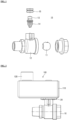
- FIG. 2 is a diagram illustrating a coupling state of a valve actuator and a ball valve according to an exemplary embodiment of the present disclosure
- FIG. 3 is an exterior perspective view of the valve actuator illustrated in FIG. 2 .
- a plate 20 may be installed above the ball valve 10, and the valve actuator 100 may be coupled to the plate 20.
- the plate 20 may be fixed to an upper end of the ball valve 10 by a fastening member such as a fastening screw, etc., and the valve actuator 100 may be fixed to the plate 20 by the fastening member such as the fastening screw, etc.
- the valve actuator 100 includes a case 110.
- the case 110 provides a space in which a motor 120 and a gear assembly provided in the valve actuator 100 are installed, the motor 120 is installed on an upper surface of the case 110 outside the case 110, and the gear assembly is disposed in an internal space of the case 110.
- the motor 120 may be a motor of a type in which RPM control is accurate. However, this is not required, and the motor 120 may be a motor of a type in which the RPM control is inaccurate. That is, since the valve actuator according to the exemplary embodiment of the present disclosure may selectively transmit power by a mechanical structure, damage to the gear assembly may be prevented and the ball valve may be accurately controlled while using the motor of the type in which the RPM control is inaccurate.
- FIG. 4 is an exploded perspective view of the valve actuator illustrated in FIG. 3
- FIG. 5 is a perspective view illustrating a coupling state of a gear assembly illustrated in FIG. 4
- FIG. 6 is a bottom perspective view of the gear assembly illustrated in FIG. 5 .
- FIG. 7 is a view illustrating a state in which an inner wheel portion and an outer wheel portion integrally rotate as a plan view of a third gear provided in the gear assembly illustrated in FIG. 4
- FIG. 8 is a view illustrating a state in which power transmission of the inner wheel portion and the outer wheel portion is blocked as the plan view of a third gear provided in the gear assembly illustrated in FIG. 4 .
- the gear assembly includes an input gear 131 coupled and/or connected to a rotational shaft of the motor 120 and receiving the driving force of the motor 120, an output gear 132 coupled to a stem (13) of the ball valve (10) and transmitting rotational force of the input gear 131 to the stem (13) of the vail valve (10), and at least one power transmission gear transmitting the rotational force of the input gear 131 to the output gear 132.
- the power transmission gear is constituted by third to fifth gears, but the number of power transmission gears may be appropriately changed.
- the first gear 131 includes a tooth portion 131a.
- the third gear 133 directly coupled to the first gear 131 includes an outer wheel portion 133A and an inner wheel portion 133B installed at an inner side of the outer wheel portion 133A, and the outer wheel portion 133A and the inner wheel portion 133B are connected by a selective power transmission unit.
- the inner wheel portion 133B may also rotate integrally with the outer wheel portion 133A, and while the inner wheel portion 133B does not rotate, only the outer wheel portion 133A may also rotate.
- the selective power transmission unit includes a plurality of concave portions 133B-1 and a plurality of convex 133B-2 alternately formed on an outer circumferential surface of the inner wheel portion 133B, balls 133B-3 positioned at the plurality of concave portions 133B-1, and elastically pressed toward a center of the inner wheel portion 133B, and springs 133B-4 elastically pressing the ball 133B-3.
- the outer wheel portion 133A includes a plurality of spring installation portions 133A-1 in which the springs 133B-4 elastically pressing the balls 133B-3 are installed, respectively.
- Each of the number of concave portions 133B-1, the number of convex portions 133B-2, and the number of balls 133B-3, the number of spring installation portions 133A-1 of the outer wheel portion 133A, etc. may be provided as four as illustrated, but this is not limitative, and preferably, each may be provided as two or more.
- the number of concave portions 133B-1, the number of convex portions 133B-2, and the number of balls 133B-3, and the number of spring installation portions 133A-1 of the outer wheel portion 133A may increase or decrease as large as required spring force.
- the concave portions 133B-1 and the convex portions 133B-2 of the inner wheel portion 133B, the number of balls 133B-3, the number of spring installation portions 133A-1 of the outer wheel portion 133A, etc. is provided as even number such as 2, 4, 6, etc.
- the concave portions 133B-1 and the convex portions 133B-2, the balls 133B-3, and the spring installation portions 133A-1 may be arranged at symmetric locations around the inner wheel portion 133B.
- the spring 133B-4 has spring force of a degree of being compressed when the second gear 132 rotates in a clockwise direction or counterclockwise direction and is in physical contact with the stopper 140, and then a torque value of a radial conversion torque or more of the spring force is applied.
- the outer wheel portion 133A includes a first tooth portion 133a physically directly coupled to the tooth portion 131a of the first gear 131 and the inner wheel portion 133B includes a second tooth portion 133ba disposed below the first tooth portion 133a on an axis of the third gear 133.
- a first tooth portion 134a of a fourth gear 134 is directly physically coupled to the second tooth portion 133b of the third gear 133, and the second tooth portion 134b is positioned below the first tooth portion 134a on the axis of the fourth gear 134.
- a fifth gear 135 includes a first tooth portion 135a physically directly coupled to the second tooth portion 134b of the fourth gear 134, and a second tooth portion 135b positioned above the first tooth portion 135a on the axis of the fifth gear 135, and a tooth portion 132a of the second gear 132 is physically directly coupled to the second tooth portion 135b of the fifth gear 135.
- the tooth portion of the second gear 132 may be formed in an arc shape.
- the second gear 132 further includes a stem coupling portion 132c coupled to a stem 13 of the ball valve 10.
- the driving force of the motor 120 is transmitted to the output gear 132 sequentially through the first gear 131, the third gear 133, the fourth gear 134, and the fifth gear 135, and appropriate speed reduction is made during the power transmission process.
- valve actuator Accordingly, the actuation of the valve actuator according to an exemplary embodiment of the present disclosure will be described with reference to FIGS. 7 to 11 .
- FIG. 9 is a view illustrating an actuation state of the gear assembly within a normal actuation range of the valve actuator
- FIG. 10 is a view illustrating the actuation state of the gear assembly when the motor is driven, the second gear rotates in the counterclockwise direction in the state illustrated in FIG. 9 , and gear engagement is released
- FIG. 11 is a view illustrating the actuation state of the gear assembly when the motor is driven the second gear rotates in the clockwise direction in the state illustrated in FIG. 9 , and the gear engagement is released.
- the stopper 140 for physically limiting a rotational angle of the second gear 132 is installed inside the case 110.
- FIG. 9 illustrates a state in which two stoppers 140 are installed to limit rotational angles in the clockwise and counterclockwise directions of the second gear 132, respectively, but when the motor 120 is configured to rotate in any one direction of the clockwise direction or the counterclockwise direction, only one stopper 140 may also be installed to limit only the rotational angle in any one direction of the clockwise direction or the counterclockwise direction of the second gear 132.
- the ball 133B-3 of the selective power transmission unit is pressed by the spring 133B-4 to be positioned within the concave portion 133B-1 of the inner wheel portion 133B.
- the "normal actuation range of the valve actuator” means a state in which driving of the motor 120 is stopped and an initial state in which the motor 120 is driven in order to close the path by controlling the ball valve 10.
- valve actuator even after the second gear 132 is in contact with the stopper 140, the driving of the motor 120 is not sopped, but the motor 120 is continuously driven.
- the ball 133B-3 installed between the outer wheel portion 133A and the inner wheel portion 133B is pressed while the outer wheel portion 133A of the third gear 133 rotates, and as a result, the ball 133B-3 is positioned at the convex portion 133B-2 of the inner wheel portion 133B while the spring 133B-4 is compressed.
- valve actuator of the present disclosure since the spring force is actuated in a radial direction of the gear, durability and driving stability are secured when applying a torque in a gear rotation direction.
- valve actuator of the present disclosure need not include a separate electronic switch and a separate PCB for the motor stop signal, the instability of the electronic switch or the electronic sensor is removed, and the complexity and the material cost of the device are improved.
- a contact portion pressing the inner wheel portion is formed in a ball structure, the ball rotates even in high-speed rotation, thereby improving the durability and the driving stability.
- valve actuator for controlling the ball valve provided in the air conditioner has been described, but the valve actuator according to the present disclosure may be used in a valve for controlling a path of gas or a fluid.
Landscapes
- Engineering & Computer Science (AREA)
- General Engineering & Computer Science (AREA)
- Mechanical Engineering (AREA)
- Electrically Driven Valve-Operating Means (AREA)
Applications Claiming Priority (1)
| Application Number | Priority Date | Filing Date | Title |
|---|---|---|---|
| KR1020210109661A KR102585156B1 (ko) | 2021-08-19 | 2021-08-19 | 밸브 액튜에이터 |
Publications (2)
| Publication Number | Publication Date |
|---|---|
| EP4137729A1 true EP4137729A1 (fr) | 2023-02-22 |
| EP4137729B1 EP4137729B1 (fr) | 2026-06-10 |
Family
ID=82898889
Family Applications (1)
| Application Number | Title | Priority Date | Filing Date |
|---|---|---|---|
| EP22189789.5A Active EP4137729B1 (fr) | 2021-08-19 | 2022-08-10 | Actionneur de soupape |
Country Status (3)
| Country | Link |
|---|---|
| US (1) | US12000498B2 (fr) |
| EP (1) | EP4137729B1 (fr) |
| KR (1) | KR102585156B1 (fr) |
Families Citing this family (1)
| Publication number | Priority date | Publication date | Assignee | Title |
|---|---|---|---|---|
| USD1132072S1 (en) | 2024-05-31 | 2026-06-30 | Sharkninja Operating Llc | Beverage dispenser |
Citations (7)
| Publication number | Priority date | Publication date | Assignee | Title |
|---|---|---|---|---|
| US2459092A (en) * | 1945-04-19 | 1949-01-11 | Dana Corp | Slip clutch power take-off unit |
| JPH0338761B2 (fr) | 1982-03-27 | 1991-06-11 | Fujitsu Ltd | |
| US5916325A (en) * | 1997-04-03 | 1999-06-29 | Dresser Industries, Inc. | Actuator assembly and torque limiting system for same |
| DE10122272A1 (de) * | 2001-05-08 | 2002-11-14 | Bosch Gmbh Robert | Überlastkupplung zur Übertragung eines in der Höhe begrenzten Drehmoments |
| JP2007002846A (ja) * | 2005-06-20 | 2007-01-11 | Robert Bosch Gmbh | 作動機構に用いられる作動器 |
| KR100750404B1 (ko) * | 2006-08-09 | 2007-08-17 | (주)모토닉 | 전자제어식 쓰로틀밸브장치 |
| KR20090073402A (ko) * | 2007-12-31 | 2009-07-03 | 주식회사 밸콘 | 전동 볼밸브 |
Family Cites Families (5)
| Publication number | Priority date | Publication date | Assignee | Title |
|---|---|---|---|---|
| US5131623A (en) * | 1991-02-25 | 1992-07-21 | Taco, Inc. | Actuator and zone valve |
| WO2000068556A1 (fr) * | 1999-05-10 | 2000-11-16 | Hitachi, Ltd. | Dispositif etrangleur de moteur a combustion interne |
| KR100815162B1 (ko) * | 2007-04-03 | 2008-03-19 | (주)모토닉 | 차량용 스로틀 장치 |
| JP6559399B2 (ja) * | 2014-02-27 | 2019-08-14 | 株式会社エクセディ | ダンパー装置 |
| JP7188351B2 (ja) * | 2019-02-13 | 2022-12-13 | トヨタ自動車株式会社 | 車両用変速機および車両用変速機の制御装置 |
-
2021
- 2021-08-19 KR KR1020210109661A patent/KR102585156B1/ko active Active
-
2022
- 2022-08-09 US US17/883,818 patent/US12000498B2/en active Active
- 2022-08-10 EP EP22189789.5A patent/EP4137729B1/fr active Active
Patent Citations (7)
| Publication number | Priority date | Publication date | Assignee | Title |
|---|---|---|---|---|
| US2459092A (en) * | 1945-04-19 | 1949-01-11 | Dana Corp | Slip clutch power take-off unit |
| JPH0338761B2 (fr) | 1982-03-27 | 1991-06-11 | Fujitsu Ltd | |
| US5916325A (en) * | 1997-04-03 | 1999-06-29 | Dresser Industries, Inc. | Actuator assembly and torque limiting system for same |
| DE10122272A1 (de) * | 2001-05-08 | 2002-11-14 | Bosch Gmbh Robert | Überlastkupplung zur Übertragung eines in der Höhe begrenzten Drehmoments |
| JP2007002846A (ja) * | 2005-06-20 | 2007-01-11 | Robert Bosch Gmbh | 作動機構に用いられる作動器 |
| KR100750404B1 (ko) * | 2006-08-09 | 2007-08-17 | (주)모토닉 | 전자제어식 쓰로틀밸브장치 |
| KR20090073402A (ko) * | 2007-12-31 | 2009-07-03 | 주식회사 밸콘 | 전동 볼밸브 |
Also Published As
| Publication number | Publication date |
|---|---|
| EP4137729B1 (fr) | 2026-06-10 |
| US20230054114A1 (en) | 2023-02-23 |
| US12000498B2 (en) | 2024-06-04 |
| KR20230027644A (ko) | 2023-02-28 |
| KR102585156B1 (ko) | 2023-10-06 |
Similar Documents
| Publication | Publication Date | Title |
|---|---|---|
| JP4896271B2 (ja) | アクチュエータ及び調整要素 | |
| WO2004001262A1 (fr) | Poussoir de vanne | |
| JP6934858B2 (ja) | 特に膨張ストローク及び/又は圧縮比を調節する内燃機関の調節軸へ連結するためのアクチュエータ | |
| EP4160063B1 (fr) | Actionneur de soupape | |
| CN117128351A (zh) | 阀致动器 | |
| US8382595B2 (en) | Torque limiting driveline | |
| US5791190A (en) | Counter gear in a transmission gear mechanism for a radio controlled toy car | |
| JP3932322B2 (ja) | 回転継手 | |
| US12000498B2 (en) | Valve actuator | |
| JP4660788B2 (ja) | 弁 | |
| EP4141300B1 (fr) | Actionneur de soupape | |
| US20050006832A1 (en) | Torque limiter and automatic open close unit for toilet seat and seat cover using the same | |
| EP4137728A1 (fr) | Actionneur de soupape | |
| CN107165727B (zh) | 用于排气瓣门的驱动系统 | |
| US7040989B2 (en) | Power transmission device | |
| CN107387187A (zh) | 发动机传动设备 | |
| US6763805B2 (en) | Intake air throttle valve device | |
| JP5254345B2 (ja) | 車輌のレンジ切換え装置 | |
| KR20020084210A (ko) | 전동 클러치 디스크 | |
| JPS6380039A (ja) | エンジンのスロツトル弁制御装置 | |
| US7666100B2 (en) | Power transmission device | |
| EP0866512B1 (fr) | Commutateur hyperfréquence | |
| JP2019065943A (ja) | 小型構造の逆入力遮断クラッチ | |
| JPH0250332B2 (fr) | ||
| KR200205441Y1 (ko) | 회전력 역전달 방지장치 |
Legal Events
| Date | Code | Title | Description |
|---|---|---|---|
| PUAI | Public reference made under article 153(3) epc to a published international application that has entered the european phase |
Free format text: ORIGINAL CODE: 0009012 |
|
| STAA | Information on the status of an ep patent application or granted ep patent |
Free format text: STATUS: REQUEST FOR EXAMINATION WAS MADE |
|
| 17P | Request for examination filed |
Effective date: 20220910 |
|
| AK | Designated contracting states |
Kind code of ref document: A1 Designated state(s): AL AT BE BG CH CY CZ DE DK EE ES FI FR GB GR HR HU IE IS IT LI LT LU LV MC MK MT NL NO PL PT RO RS SE SI SK SM TR |
|
| RBV | Designated contracting states (corrected) |
Designated state(s): AL AT BE BG CH CY CZ DE DK EE ES FI FR GB GR HR HU IE IS IT LI LT LU LV MC MK MT NL NO PL PT RO RS SE SI SK SM TR |
|
| STAA | Information on the status of an ep patent application or granted ep patent |
Free format text: STATUS: EXAMINATION IS IN PROGRESS |
|
| 17Q | First examination report despatched |
Effective date: 20240923 |
|
| GRAP | Despatch of communication of intention to grant a patent |
Free format text: ORIGINAL CODE: EPIDOSNIGR1 |
|
| STAA | Information on the status of an ep patent application or granted ep patent |
Free format text: STATUS: GRANT OF PATENT IS INTENDED |
|
| INTG | Intention to grant announced |
Effective date: 20260216 |
|
| GRAS | Grant fee paid |
Free format text: ORIGINAL CODE: EPIDOSNIGR3 |
|
| GRAA | (expected) grant |
Free format text: ORIGINAL CODE: 0009210 |
|
| STAA | Information on the status of an ep patent application or granted ep patent |
Free format text: STATUS: THE PATENT HAS BEEN GRANTED |
|
| AK | Designated contracting states |
Kind code of ref document: B1 Designated state(s): AL AT BE BG CH CY CZ DE DK EE ES FI FR GB GR HR HU IE IS IT LI LT LU LV MC MK MT NL NO PL PT RO RS SE SI SK SM TR |
|
| REG | Reference to a national code |
Ref country code: CH Ref legal event code: F10 Free format text: ST27 STATUS EVENT CODE: U-0-0-F10-F00 (AS PROVIDED BY THE NATIONAL OFFICE) Effective date: 20260610 Ref country code: GB Ref legal event code: FG4D |
|
| REG | Reference to a national code |
Ref country code: IE Ref legal event code: FG4D |
|
| REG | Reference to a national code |
Ref country code: DE Ref legal event code: R096 Ref document number: 602022038113 Country of ref document: DE |