EP4137731B1 - Universeller drehmomentanzeigeradapter mit formschlüssiger verriegelungsfunktion - Google Patents
Universeller drehmomentanzeigeradapter mit formschlüssiger verriegelungsfunktion Download PDFInfo
- Publication number
- EP4137731B1 EP4137731B1 EP22188855.5A EP22188855A EP4137731B1 EP 4137731 B1 EP4137731 B1 EP 4137731B1 EP 22188855 A EP22188855 A EP 22188855A EP 4137731 B1 EP4137731 B1 EP 4137731B1
- Authority
- EP
- European Patent Office
- Prior art keywords
- nut
- sleeve
- torque level
- visual indicator
- assembly
- Prior art date
- Legal status (The legal status is an assumption and is not a legal conclusion. Google has not performed a legal analysis and makes no representation as to the accuracy of the status listed.)
- Active
Links
Images


Classifications
-
- F—MECHANICAL ENGINEERING; LIGHTING; HEATING; WEAPONS; BLASTING
- F16—ENGINEERING ELEMENTS AND UNITS; GENERAL MEASURES FOR PRODUCING AND MAINTAINING EFFECTIVE FUNCTIONING OF MACHINES OR INSTALLATIONS; THERMAL INSULATION IN GENERAL
- F16L—PIPES; JOINTS OR FITTINGS FOR PIPES; SUPPORTS FOR PIPES, CABLES OR PROTECTIVE TUBING; MEANS FOR THERMAL INSULATION IN GENERAL
- F16L19/00—Joints in which sealing surfaces are pressed together by means of a member, e.g. a swivel nut, screwed on, or into, one of the joint parts
- F16L19/02—Pipe ends provided with collars or flanges, integral with the pipe or not, pressed together by a screwed member
- F16L19/025—Pipe ends provided with collars or flanges, integral with the pipe or not, pressed together by a screwed member the pipe ends having integral collars or flanges
-
- F—MECHANICAL ENGINEERING; LIGHTING; HEATING; WEAPONS; BLASTING
- F16—ENGINEERING ELEMENTS AND UNITS; GENERAL MEASURES FOR PRODUCING AND MAINTAINING EFFECTIVE FUNCTIONING OF MACHINES OR INSTALLATIONS; THERMAL INSULATION IN GENERAL
- F16B—DEVICES FOR FASTENING OR SECURING CONSTRUCTIONAL ELEMENTS OR MACHINE PARTS TOGETHER, e.g. NAILS, BOLTS, CIRCLIPS, CLAMPS, CLIPS OR WEDGES; JOINTS OR JOINTING
- F16B31/00—Screwed connections specially modified in view of tensile load; Break-bolts
- F16B31/02—Screwed connections specially modified in view of tensile load; Break-bolts for indicating the attainment of a particular tensile load or limiting tensile load
- F16B31/024—Screwed connections specially modified in view of tensile load; Break-bolts for indicating the attainment of a particular tensile load or limiting tensile load with the bottom of the nut or of the head of the bolt having gaps which close as the bolt tension increases, e.g. with lips or with a load-indicating flange
-
- F—MECHANICAL ENGINEERING; LIGHTING; HEATING; WEAPONS; BLASTING
- F16—ENGINEERING ELEMENTS AND UNITS; GENERAL MEASURES FOR PRODUCING AND MAINTAINING EFFECTIVE FUNCTIONING OF MACHINES OR INSTALLATIONS; THERMAL INSULATION IN GENERAL
- F16B—DEVICES FOR FASTENING OR SECURING CONSTRUCTIONAL ELEMENTS OR MACHINE PARTS TOGETHER, e.g. NAILS, BOLTS, CIRCLIPS, CLAMPS, CLIPS OR WEDGES; JOINTS OR JOINTING
- F16B31/00—Screwed connections specially modified in view of tensile load; Break-bolts
- F16B31/02—Screwed connections specially modified in view of tensile load; Break-bolts for indicating the attainment of a particular tensile load or limiting tensile load
- F16B31/028—Screwed connections specially modified in view of tensile load; Break-bolts for indicating the attainment of a particular tensile load or limiting tensile load with a load-indicating washer or washer assembly
-
- F—MECHANICAL ENGINEERING; LIGHTING; HEATING; WEAPONS; BLASTING
- F16—ENGINEERING ELEMENTS AND UNITS; GENERAL MEASURES FOR PRODUCING AND MAINTAINING EFFECTIVE FUNCTIONING OF MACHINES OR INSTALLATIONS; THERMAL INSULATION IN GENERAL
- F16B—DEVICES FOR FASTENING OR SECURING CONSTRUCTIONAL ELEMENTS OR MACHINE PARTS TOGETHER, e.g. NAILS, BOLTS, CIRCLIPS, CLAMPS, CLIPS OR WEDGES; JOINTS OR JOINTING
- F16B7/00—Connections of rods or tubes, e.g. of non-circular section, mutually, including resilient connections
- F16B7/04—Clamping or clipping connections
- F16B7/0406—Clamping or clipping connections for rods or tubes being coaxial
- F16B7/0426—Clamping or clipping connections for rods or tubes being coaxial for rods or for tubes without using the innerside thereof
-
- F—MECHANICAL ENGINEERING; LIGHTING; HEATING; WEAPONS; BLASTING
- F16—ENGINEERING ELEMENTS AND UNITS; GENERAL MEASURES FOR PRODUCING AND MAINTAINING EFFECTIVE FUNCTIONING OF MACHINES OR INSTALLATIONS; THERMAL INSULATION IN GENERAL
- F16B—DEVICES FOR FASTENING OR SECURING CONSTRUCTIONAL ELEMENTS OR MACHINE PARTS TOGETHER, e.g. NAILS, BOLTS, CIRCLIPS, CLAMPS, CLIPS OR WEDGES; JOINTS OR JOINTING
- F16B7/00—Connections of rods or tubes, e.g. of non-circular section, mutually, including resilient connections
- F16B7/18—Connections of rods or tubes, e.g. of non-circular section, mutually, including resilient connections using screw-thread elements
- F16B7/182—Connections of rods or tubes, e.g. of non-circular section, mutually, including resilient connections using screw-thread elements for coaxial connections of two rods or tubes
-
- F—MECHANICAL ENGINEERING; LIGHTING; HEATING; WEAPONS; BLASTING
- F16—ENGINEERING ELEMENTS AND UNITS; GENERAL MEASURES FOR PRODUCING AND MAINTAINING EFFECTIVE FUNCTIONING OF MACHINES OR INSTALLATIONS; THERMAL INSULATION IN GENERAL
- F16B—DEVICES FOR FASTENING OR SECURING CONSTRUCTIONAL ELEMENTS OR MACHINE PARTS TOGETHER, e.g. NAILS, BOLTS, CIRCLIPS, CLAMPS, CLIPS OR WEDGES; JOINTS OR JOINTING
- F16B21/00—Means for preventing relative axial movement of a pin, spigot, shaft or the like and a member surrounding it; Stud-and-socket releasable fastenings
- F16B21/10—Means for preventing relative axial movement of a pin, spigot, shaft or the like and a member surrounding it; Stud-and-socket releasable fastenings by separate parts
- F16B21/16—Means for preventing relative axial movement of a pin, spigot, shaft or the like and a member surrounding it; Stud-and-socket releasable fastenings by separate parts with grooves or notches in the pin or shaft
- F16B21/18—Means for preventing relative axial movement of a pin, spigot, shaft or the like and a member surrounding it; Stud-and-socket releasable fastenings by separate parts with grooves or notches in the pin or shaft with circlips or like resilient retaining devices, i.e. resilient in the plane of the ring or the like; Details
- F16B21/186—Means for preventing relative axial movement of a pin, spigot, shaft or the like and a member surrounding it; Stud-and-socket releasable fastenings by separate parts with grooves or notches in the pin or shaft with circlips or like resilient retaining devices, i.e. resilient in the plane of the ring or the like; Details external, i.e. with contracting action
-
- F—MECHANICAL ENGINEERING; LIGHTING; HEATING; WEAPONS; BLASTING
- F16—ENGINEERING ELEMENTS AND UNITS; GENERAL MEASURES FOR PRODUCING AND MAINTAINING EFFECTIVE FUNCTIONING OF MACHINES OR INSTALLATIONS; THERMAL INSULATION IN GENERAL
- F16L—PIPES; JOINTS OR FITTINGS FOR PIPES; SUPPORTS FOR PIPES, CABLES OR PROTECTIVE TUBING; MEANS FOR THERMAL INSULATION IN GENERAL
- F16L2201/00—Special arrangements for pipe couplings
- F16L2201/10—Indicators for correct coupling
Definitions
- the present application relates to a torque indicating device for fluid connector fittings.
- the present disclosure relates to a fluid fitting assembly that provides a visual indication to show that the fluid fitting assembly has been torqued properly.
- the fitting assembly also may provide a positive locking feature to prevent nut loosening and loss of clamp load during use.
- the fitting assembly has a torque indicating mechanism which has a visual indicator that changes visually with torque level as the nut is tightened, such as for example a color indicator changing color from red to green, when the desired operational torque value is reached, thus indicating that a proper torque has been achieved.
- a secondary visual indicator between a primary visual indicator may show that the torque value is below the desired value.
- the fitting assembly further includes a retention mechanism that provides a desired amount of resistance to loosening of the component parts of the assembly during use and while still permitting the fluid fitting assembly to be disassembled as needed for maintenance or repair, and then readily reassembled.
- This fitting assembly of the present disclosure is suitable for use on any shoulder nut and wire-on nut configuration, such as for example configurations with flared, flareless, beam seal, or ball nose ends.
- the fitting assembly of the present disclosure also is suitable for use on various fluid connection configurations for various applications, including for example hose assemblies, tube assemblies, fuel manifolds, hydraulic fittings, and other applications in which nuts are used.
- the fitting assembly may be employed in accordance with various industry standards, such as for example SAE, AS, ABS, and MIL industry standards, and otherwise may be configured for various other fitting dimensions and overall envelope configurations. Additionally, assembly process modifications or changes, and special tool or fixture configurations, generally are not required to assemble the fitting assembly.
- This fitting assembly generally is adaptable to any suitable connector parameters in common usage, such as being adaptable for various sizes, various materials, and various temperatures of operation including higher operating temperature, without requiring structural modification in relation to typical parameter needs or industry standards.
- the fitting assembly does not require a torque wrench to verify the operational torque value of the fluid connection.
- the configuration of the fitting assembly also prevents the nut from backing up or loosening due to vibration effects, environmental conditions, and other dynamic external loads, and thus also prevents loss of clamp load, thread pretension, and material or strain relaxation.
- an aspect of the invention is a fitting assembly that includes an indicator assembly that provides a visual indication of torque value to verify when the desired operational torque value is achieved.
- the fitting assembly includes a nut having a first end and a second end opposite from the first end; a visual indicator assembly positioned on the first end of the nut, the visual indicator assembly including a plurality of visual indicators that provide a visual indication of a torque level being applied to the nut; a sleeve attached to the nut and including a window through which a portion of the plurality of visual indicators is visible based on the torque level being applied to the nut; and a resilient member that couples the sleeve to the nut.
- the resilient member biases the sleeve in a fixed position and the nut rotates relative to the sleeve, whereby the visual indicator assembly rotates relative to the sleeve to alter which portion of the visual indicator assembly is visible through the window to provide a visual indication of when the torque level being applied to the nut is a desired operational torque level.
- the visual indicator assembly may include a first visual indicator that indicates an insufficient torque level is being applied to the nut, and a second visual indicator different from the first visual indicator (e.g., different color indicators) that indicates the desired operational torque level is being applied to the nut.
- the visual indicator assembly further may include an intermediate visual indicator that is different from and positioned between the first visual indicator and the second visual indicator, wherein the first visual indicator indicates a zero torque level being applied to the nut, the intermediate visual indicator indicates that a non-zero but insufficient torque level is being applied to the nut, and the second visual indicator indicates that the desired operational torque level is being applied to the nut.
- the visual indicator assembly further may include a plurality of torque level markings corresponding to different torque levels, and the sleeve further may include a pointer positioned in the window that points to one of the plurality of torque level markings corresponding to a torque level being applied to the nut.
- the sleeve includes a telescoping portion that is positioned inserted within the nut, and a cover portion that is positioned extending around and over the first end of the nut and the visual indicator assembly.
- the resilient member is a coil spring having a first end configured as a spring leg that is positioned inserted within a spring groove formed in the nut, and a second end that is positioned against the sleeve.
- the fitting assembly further includes a spring pin that is configurable from an extended position corresponding to a zero-torque state of the torque level being applied to the nut to a retracted position corresponding to a non-zero torque state of the torque level being applied to the nut; wherein in the extended position the spring pin couples the sleeve to the nut such that the sleeve and the nut rotate together, and in the retracted position the spring pin coupling of the sleeve to the nut is disengaged such that the nut rotates relative to the sleeve.
- the spring pin is a separate component from the nut and the sleeve, and in the extended position the spring pin is positioned in a nut pin hole in the nut and extends through a sleeve pin hole in the sleeve to couple the sleeve to the nut, and in the retracted position the spring pin does not extend through the sleeve pin hole to disengage the nut from the sleeve.
- the spring pin has a spiraled or rolled pin configuration.
- the fitting assembly further includes an audio indicator including a protrusion fixed to an internal surface of the sleeve, wherein as the nut rotates relative to the sleeve, the spring pin contacts the protrusion to provide an audio indication of when the desired operational torque level is being applied to the nut.
- the spring pin is configured as a bend in a surface of the sleeve, and in the extended position the spring pin is positioned in a nut pin hole in the nut to couple the sleeve to the nut, and in the retracted position the spring pin does not extend into the nut pin hole to disengage the nut from the sleeve.
- the second end of the nut includes internal threads for connecting with external threads of a fluid section, and the nut further includes an undercut that receives a portion of the sleeve, the undercut being a deeper cut relative to a minimum full thread depth of the internal threads.
- the fitting assembly further includes a wire positioned within a groove in the nut and against a portion of the sleeve.
- a fluid connection assembly including the fitting assembly according to any of the embodiments and a nipple fluid section that is connected to the nut through the first end of the nut.
- the nipple fluid connection includes an external surface having a serrated portion
- the fitting assembly includes a positive locking feature that interacts with the serrated portion of the nipple fluid connection to positively lock a position of the nut to prevent nut loosening during use.
- the positive locking feature may include a vertical spring leg of the resilient member, and the vertical spring leg moves up and down over the serrated portion of the nipple fluid section such that when the desired operational torque level is applied to the nut, the vertical spring leg is positioned within a groove of the serrated portion to positively lock the position of the nut.
- the positive locking feature further may include a spring tab of the sleeve that ends in a pawl, and the spring tab moves up and down over the serrated portion of the nipple fluid section such that when the desired operational torque level is being applied to the nut, the pawl is positioned within a groove of the serrated portion to positively lock the position of the nut.
- the sleeve includes a contact surface, and the vertical spring leg slides over the contact surface during a portion of nut rotation during which an insufficient torque level is being applied to the nut; and the sleeve further includes a locking window positioned adjacent to the sliding surface, and when the desired operational torque level is applied to the nut the vertical spring leg is positioned through the locking window to be positioned within the groove of the serrated portion of the nipple fluid section.
- the contact surface and the locking window of the sleeve are positioned such that the vertical leg spring slides against the contact surface during nut rotation when the torque level being applied to the nut is 75% of the desired operational torque level or less, and the vertical leg spring extends through the window and moves up and down over the serrated portion of the nipple fluid section when the torque level being applied to the nut is more than 75% of the desired operational torque level.
- the vertical spring leg is oriented at an angle relative to a radial direction of the nipple fluid section.
- Fig. 1 is a drawing depicting an exemplary embodiment of a fitting assembly 10 in a disconnected state relative to a first fluid section 12 in accordance with embodiments of the present application.
- Fig. 2 is a drawing depicting the fitting assembly 10 in a connected state relative to the first fluid section 12.
- the fitting assembly 10 also is shown mounted to a second fluid section 14, which typically is the nipple fluid connection that is joined with the first fluid section 12 by the fitting assembly 10.
- a fluid can flow between the first and second fluid sections 12 and 14, through the fitting assembly 10.
- the fitting assembly 10 is more generally applicable to various applications, including for example hose assemblies, tube assemblies, fuel manifolds, hydraulic fittings, and other applications in which nuts are used to joint fluid sections together.
- the fitting assembly 10 includes a visual indicator assembly 16 that provides an indication of whether the fitting assembly has been tightened to form the fluid connection with a desired operational torque level.
- the visual indicator assembly 16 includes a first visual indicator 18 and a second visual indicator 20 that differs from the first visual indicator 18. The difference between the first versus second visual indicators provides a visual indication as to whether the fitting assembly has been torqued to an appropriate or correct operational torque level.
- the first visual indicator 18 provides a visual indication that the fitting assembly is connected with an insufficient torque level, and including there being no torque (disconnected state).
- the second visual indicator 20 provides a visual indication that the fitting assembly is connected with an appropriate or correct operational torque level.
- the difference between the first versus second visual indicators 18 and 20 may be different colors.
- the fitting assembly 10 in Fig. 1 is not coupled to the fluid section 12 (no torque being applied) and therefore the visual indicator assembly 16 may show a red color first visual indicator 18, whereas the fitting assembly 10 in Fig. 2 is coupled to the fluid section 12 and therefore the visual indicator assembly 16 may show a green color second visual indicator 20.
- the color visual indicators may be applied to the nut using a color laser marking technique, such as for example using a master oscillator power amplifier (MOPA) color marking laser.
- MOPA master oscillator power amplifier
- Figs. 1 and 2 depict only two visual indicators, which also may be varied depending upon the size and use application of the fitting assembly. Additional and further different visual indicators may be provided intermediately between the first and second visual indicators 18 and 20 (see, e.g., Fig. 3 illustrating a third visual indicator 19 between the first visual indicator 18 and the second visual indicator 20). For example, in a color indication scheme, a yellow color indicator may be provided between the red and green color indicators.
- red may correspond to full disconnection and zero torque
- yellow may correspond to a non-zero torque being applied but below the proper operational torque level
- green may correspond to torque being applied at the proper operational torque level.
- alternative colors may be used, or non-color based visual differences may be used, to provide the different visual indicators.
- other methods of forming the different visual indicators may include, for example, applying a plastic (Nylon or similar) ring such as by machining or injection molding, 3D printing the indicators, or press-fitting or gluing an indicator ring over the nut surface.
- a fluorescent paint also may be employed to form the visual indicator assembly, which is particularly suitable for use in dark environments.
- the visual indicator assembly 16 includes at least the first visual indicator 18 that indicates an insufficient torque level is being applied to the nut, and the second visual indicator 20 different from the first visual indicator that indicates the desired operational torque level is being applied to the nut.
- the visual indicator assembly 16 further may include the intermediate visual indicator 19 that is different from and positioned between the first visual indicator and the second visual indicator.
- the first visual indicator indicates a zero torque level being applied to the nut
- the intermediate visual indicator indicates that a non-zero but insufficient torque level is being applied to the nut
- the second visual indicator indicates that the desired operational torque level is being applied to the nut.
- Fig. 3 is a drawing depicting an exploded view of the fitting assembly 10, which illustrates the principal components of the fitting assembly 10.
- the fitting assembly 10 includes a nut 22, a sleeve 24, and a resilient member 26.
- Fig. 4 is a drawing depicting the exploded view of the fitting assembly 10 of Fig. 3 , with the nut 22 shown in cross-section to depict the internal configuration of the nut 22.
- the fitting assembly 10 includes a nut having a first end and a second end opposite from the first end; a visual indicator assembly positioned on the first end of the nut, the visual indicator assembly including a plurality of visual indicators that provide a visual indication of a torque level being applied to the nut; a sleeve attached to the nut and including a window through which a portion of the plurality of visual indicators is visible based on the torque level being applied to the nut; and a resilient member that couples the sleeve to the nut.
- the resilient member biases the sleeve in a fixed position and the nut rotates relative to the sleeve, whereby the visual indicator assembly rotates relative to the sleeve to alter which portion of the visual indicator assembly is visible through the window to provide a visual indication of when the torque level being applied to the nut is a desired operational torque level
- the nut 22 includes internal threads 28 for mating with the first fluid section 12, and an internal face 30 for receiving the sleeve 24 and the resilient member 26.
- the nut 22 further includes a first end 32 and a second end 34 opposite from the first end 32, and the visual indicator assembly 16 is located on the first end 32 being applied using laser marking or other suitable method referenced above.
- the nut 22 further includes a spring groove 36 (see particularly Fig. 4 ) for receiving the resilient member 26 and spring pins 38 for initially mounting and aligning the sleeve 24 relative to the nut, as further detailed below.
- the spring groove 36 and holes for the spring pins 38 may be machined into the nut 22 from the threaded second end 34 of the nut to avoid additional secondary operations.
- the nut may be machined with double or triple start threads depending on the size of the nut. With the described configuration of the fitting assembly, installation time generally is reduced by approximately half of the time for double start threads, and approximately one-third of the time for triple start threads, without contributing additional cost.
- the use of multi-start threads is a well-proven robustness method as compared to conventional tapered threads, which is particularly suitable for fluid connectors used in aerospace applications.
- Fig. 3 also illustrates a close-up view of an exemplary configuration of the spring pins 38 for use in the example of Figs. 3 and 4 .
- the spring pins 38 may be configured to have a spiraled or rolled pin configuration to provide some resiliency in the interaction of the spring pins within the corresponding holes in the nut 22.
- the sleeve 24 is formed as a single, integrated piece of material.
- the sleeve 24 may be made of a suitable ferrous alloy, non-ferrous alloy, steel or a steel alloy or stainless steel, precipitation-hardening stainless steel, nickel-base alloy, cobalt-base alloy, tool steel and high-speed steel, a functional alloy (Invar ® , Kovar ® ), aluminum, titanium, composite, or a polymer.
- the sleeve may be made through either one or combination of processes such as a sheet metal processing, additive manufacturing processing, machining, casting, injection molding, and metal injection molding.
- the sleeve alternatively can be formed of multiple pieces, which are joined together by any suitable joining method such as welding, brazing, spot welding, folding, bending, crimping, and gluing.
- the sleeve 24 includes a telescoping end 39 and a cover end 40 opposite from the telescoping end 39, with the cover end 40 being widened relative to the telescoping end 39.
- the telescoping end 39 is inserted into the nut 22 and essentially snap fit against the internal face 30 of the nut.
- the cover end 40 of the sleeve 24 is positioned extending around and over the first end 32 of the nut 22 and the visual indicator assembly 16.
- the cover portion 40 of the nut 24 includes windows 42 through which a portion of the visual indicator assembly is visible based on the torque level being applied to the nut, such as either of the first or second visual indicators 18 and 20.
- An additional intermediate visual indicator 19, if present and positioned between the first and second visual indicators, may be visible (as shown in Figs. 1 and 2 ) depending on the rotational position and corresponding torque level that is being applied to the nut.
- the sleeve 24 further includes pin holes 44 for initially receiving the spring pins 38 to initially align the sleeve with the nut.
- the resilient member 26 may be configured as a coil spring having a round, square, or other suitable polygon cross-sectional shape.
- the resilient member may be configured as a wave spring with a flat or round shape, although a coil spring configuration has proven to be economical with better dimensional adaptability and spring stiffness. Accordingly, the resilient member 26 also is referred to interchangeably as coil spring 26.
- the coil spring 26 is inserted into the nut 22 oppositely from the sleeve 24.
- the coil spring 26 has a first end configured as spring leg 48 that extends through the spring groove 36 of the nut, and a second end that is positioned against the sleeve.
- the resilient member or coil spring 26 couples the sleeve to the nut and operates to bias the sleeve 24 in a fixed position while the nut is tightened such that the nut rotates relative to the sleeve, as further detailed below.
- the internal face 30 of the nut 22 may be configured as an undercut that is a deeper cut relative to the minimum full thread depth of the internal threads 28.
- Fig. 5 is a drawing depicting an alternative exploded view of the fitting assembly 10, in which a sleeve is formed initially as multiple pieces rather than as a single, integral piece as in Figs. 3 and 4 .
- the telescoping end 39a initially is formed separately from the cover end 40a.
- the telescoping and cover components are subsequently joined together using any suitable joining method, such as for example by welding, brazing, spot welding, folding, bending, crimping, and/or using an adhesive.
- the individual sleeve components initially are fabricated using any suitable sheet metal processing, such as for example by stamping, cutting, bending, and rolling.
- the sleeve may be split radially.
- the coil spring 26 first is positioned on the telescoping end 39a, and the resultant assembly is inserted through the second end 34 of the nut 22.
- the cover end 40a is positioned in proper alignment over the first end 32 of the nut 22.
- Fig. 6 is a graphical depiction of a typical torque curve illustrating torque versus nut rotational angle for nut loading.
- Section I of Fig. 6 corresponds to a minimally or zero torqued state, often corresponding to hand torquing.
- Section I the nut/nipple combination is being moved toward the first fluid section but before contact is made between the nut and the sealing end surface of the first fluid section.
- Section II of Fig. 6 the nut and sealing end surface of the first fluid section have made contact.
- Section III of Fig. 6 the thread starch and clamp load increase as the nut is tightened.
- the slope curve for angle vs torque is essentially constant through Section III, with the specific clamp load depending on elasticity of the materials.
- Section III includes the proper operational torque level, with the specific torque level and positioning on the torque curve within Section III being dependent upon the circumstances and application.
- Section IV of Fig. 6 corresponds to the torque level being beyond the yield stress limit of the materials and deformation in the plastic reign, and thus the failure of the threading of the fitting assembly may start. Accordingly, it is desirable to tighten the nut until the desired operational torque level within Section III is applied, and Section IV is avoided.
- Fig. 7 is a drawing illustrating a side cross-sectional view, close-up view, and perspective view of the fitting assembly configuration during Section I of the torque curve of Fig. 6 .
- the fitting assembly 10 is shown as connecting the first fluid section 12 and the second fluid section 14.
- the fitting assembly 10 is employed in a flared fitting configuration in which the first fluid section 12 has a flared end that extends into the nipple or second fluid section 14.
- the combined fitting assembly/nipple fluid connection is placed in contact with the flare end of the first fluid section 12.
- the nut 22 is free to rotate with minimal force, often rotatable by hand, and no secure connection is made between the two fluid sections.
- the sleeve 24 is maintained in the axial direction along the direction of flow by the coil spring 26, and the sleeve 24 further is held in radial engagement with the nut 22 by the spring pins 38 extending through the outer surface of the sleeve 24.
- the close-up portion more readily illustrates the positioning of the spring leg 48 of the coil spring 26 to maintain the axial position of the sleeve 24 relative to the second fitting section 14.
- the spring leg 48 biases the internal flange 50 of the sleeve 24 against a cooperating ledge 52 of the second fluid section 14.
- the close-up view also more readily illustrates the positioning of one of the spring pins 38 positioned in a nut pin hole 54 formed within the nut 22, and extending beyond an outer surface 56 of the sleeve 24 through the corresponding sleeve pin hole 44.
- the spring pin is configurable from an extended position corresponding to a zero-torque state of the torque level being applied to the nut to a retracted position corresponding to a non-zero torque state of the torque level being applied to the nut.
- the spring pin couples the sleeve to the nut such that the sleeve and the nut rotate together, and in the retracted position the spring pin coupling of the sleeve to the nut is disengaged such that the nut rotates independently relative to the sleeve.
- Fig. 7 illustrates the zero-torque state in which the spring pin 38 couples the sleeve to the nut.
- the positioning of the spring pins 38 extending beyond the outer surface 56 of the sleeve and into the sleeve pin hole 44 sets an initial position of the sleeve 24 relative to the nut 22. Accordingly, in the extended position the spring pin 38 is positioned in the nut pin hole 54 in the nut and extends through the sleeve pin hole 44 in the sleeve to couple the sleeve to the nut.
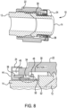
- Fig. 8 is a drawing illustrating a side cross-sectional view and a close-up view of the fitting assembly configuration during Section II of the torque curve of Fig. 6 .
- a sealed connection is beginning to form as the two fluid sections 12 and 14 become engaged.
- the torque level rises and the coil spring 26 compresses to maintain the axial positioning of the sleeve 24 against the flare interaction.
- the spring pin 38 retracts from the extended position to a retracted position relative to the pin hole 44 in the sleeve 24, and thus there no longer is a coupling connection between the spring pins 38 and the sleeve, and thus the nut and sleeve are disengaged.
- the spring pin 38 does not extend through the sleeve pin hole 44 to disengage the nut from the sleeve.
- the spring pin is free to move within a slot 46 formed in the sleeve without imparting commensurate rotation of the sleeve.
- the sleeve 24 is held in a fixed position due to the knurling or serration on the flare end and the sleeve engagement by the bias of the coil spring.
- the nut undercut 30 pushes the spring leg downwards further against the sleeve.
- the sleeve 24 disengaged from the spring pin 38 and held in a fixed position relative to the flare end and the nut, the sleeve 24 is fixed and immobile and the nut 22 is rotatable independently relative to the sleeve.
- the first visual indicator moves out of alignment with the windows 42 of the sleeve.
- Fig. 9 is a drawing illustrating a side cross-sectional view and a perspective view of the fitting assembly configuration during Section III of the torque curve of Fig. 6 .
- the sleeve 24 is disengaged from the spring pin 38 and held in a fixed position relative to the flare end and the nut, and the sleeve is fixed and immobile and the nut is rotatable independently relative to the sleeve. Disengagement of the sleeve from the nut, and independent movement of the nut relative to the sleeve, is maintained during Section III.
- the second visual indicator 20 moves into alignment with the windows 42 of the sleeve (perspective view or bottom portion of Fig. 9 ).
- such intermediate visual indicator may become aligned with the sleeve windows prior to alignment of the second visual indicator 20, to indicate the fitting assembly is being torque but currently is at an insufficient torque level.
- the visual indicator assembly rotates relative to the sleeve to alter which portion of the visual indicator assembly is visible through the window to provide a visual indication of when the torque level being applied to the nut is a desired operational torque level.
- the positioning of the second visual indicator 20 is optimized for a given fitting assembly 10 to correspond to the desired operational torque level at the corresponding position on Section III of the torque curve. In this manner, once the second visual indicator is visible through the windows of the sleeve, the operator or user knows that the appropriate operational torque level has been applied, and further torquing of the fitting assembly is prevented. An under-torque finish is avoided, and the torque level also does not enter Section IV of the torque curve (post yield stress) where failure of the fitting assembly can occur.
- the fitting assembly may further include an audio indicator in addition to the visual indicators.
- the audio indicator may include a protrusion fixed to an internal surface of the sleeve, and as the nut rotates relative to the sleeve, the spring pin contacts the protrusion to provide an audio indication of when the desired operational torque level is being applied to the nut.
- Fig. 10 is a drawing depicting an embodiment of a sleeve 24a including an audio indicator configured as a protrusion 60 that is formed on an internal surface 62 of the cover portion 40 of the sleeve 24a.
- Fig. 11 is a drawing depicting a portion of the fitting assembly 10 that shows operation of the audio indicator of Fig. 10 .
- the audio indicator protrusion 60 may be configured as one or more flat plates or forks that are fixed to the internal surface 62 of the cover portion 40 of the sleeve 24a.
- the audio indicator protrusion may be fixed by welding, brazing, spot welding, folding, bending, crimping, riveting and/or using an adhesive, or may be formed integrally with the sleeve using a molding or machining process.
- An arc angle between the audio indicator (flat plate(s)) 60 to spring pin hole(s) 44) is equal to the clamping angle ( ⁇ T ) at the desired operational torque at which the second visual indicator 20 is visible through the windows 42 of the sleeve.
- the spring pin may be configured as a bend in a surface of the sleeve that functions as the spring pin.
- the sleeve-integrated spring pin in the extended position the sleeve-integrated spring pin is positioned in a nut pin hole in the nut to couple the sleeve to the nut, and in the retracted position the sleeve-integrated spring pin does not extend into the nut pin hole to disengage the nut from the sleeve.
- Fig. 12 is a drawing depicting a portion of the fitting assembly 10 including an alternative design of a sleeve 24b in which a spring pin 64 is configured as a bend in a surface of the sleeve.
- the spring pin 64 integrated as part of the sleeve 24b, is inserted into a corresponding nut pin hole 66 formed in the nut 22.
- the integrated spring pin 64 otherwise operates comparably as the separate spring pin 38 of the previous embodiment.
- the spring pin 64 alters from an extended position to a retracted position to disengage from the nut pin hole 66 with the sleeve 24b being held in place by the coil spring.
- the sleeve 24b is in a fixed position and immobile, and the nut 22 is rotatable independently relative to the sleeve so that the visual indicator assembly 16 moves relative to the windows 42 of the sleeve.
- the visual indicator assembly may include torque value markings to provide a more precise indication of the level of torque being applied to the nut.
- the visual indicator assembly further includes a plurality of torque level markings corresponding to different torque levels
- the sleeve further includes a pointer positioned in the window that points to one of the plurality of torque level markings corresponding to a torque level being applied to the nut.
- Fig. 13 is a drawing depicting an exemplary visual indicator assembly 16c and an associated portion of a modified sleeve 24c, in which the visual indicator assembly includes torque value markings 68.
- Torque value markings 68 may be applied using any suitable marking method, such as for example MOPA laser marking methods or other suitable methods described above in connection with generally forming the visual indicator assembly. As shown in Fig. 13 , the content of the markings, for example, may resemble a torque wrench dial and include numerical values corresponding to the applied torque. The content of the torque value markings additionally or alternatively may include qualitative torque indications, such as for example Min (minimum), Nom (nominal), and Max (maximum). To associate a particular torque value marking with the torque being applied, a window 42c of the sleeve 24c may be formed to include a pointer 70. In use, the pointer 70 aligns with a particular torque value marking 68 to indicate the value of the applied torque at the respective rotational position of the nut.
- a window 42c of the sleeve 24c may be formed to include a pointer 70. In use, the pointer 70 aligns with a particular torque value marking 68 to indicate the value of the applied torque at the respective
- the fitting assembly 10 and the related variations are employed in connection with a flare end fitting configuration.
- the fitting assembly 10 is not limited to a flare end fitting configuration.
- Fig. 14 depicts the fitting assembly 10 in use in a flareless end fitting configuration in which a first fluid section 12a does not have a flare end inserted into a second fluid section (nipple) 14a.
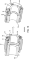
- Fig. 15 depicts the fitting assembly 10 in use in a beam seal configuration in which a first fluid section 12b and a second fluid section 14b mate and seal at planar surfaces.
- the left portions illustrate the fitting assembly in the disconnected state, and thus the first visual indicator 18 is visible.
- the right portions illustrate the fitting assembly in the connected state with the desired operational torque value being applied, and thus the second visual indicator 20 is visible.
- the fitting assembly 10 is suitable for providing torque indications in any suitable end configuration of the connected fluid sections.
- a wire-on-nut design in which a locking wire is employed to maintain positioning of the nut, is most suitable.
- a wire-on-nut design typically is used in jump size fittings, elbow fittings and similar forgings and bend tubes of higher size, and fitting seal ends with hex-on-nipple designs.
- the fitting assembly 10 also is adaptable for use in a wire-on-nut design.
- Fig. 16 is a drawing depicting the fitting assembly 10 in use in a wire-on-nut fitting configuration, with the left portion indicating the no-torque state of Section I of the torque curve, and the right portion indicating the torquing state of Sections II and III of the torque curve.
- a wire 72 is positioned within a groove formed within the nut 22 that is positioned adjacent to the second fluid section 14 and positioned against a portion of the sleeve 24.
- the sleeve 24 includes an end 24d that is modified to accommodate the wire 72.
- the wire moves along the undercut 30 formed in the nut 22 that receives the sleeve 24 and coil spring 26.
- the fitting assembly 10 otherwise operates comparably as previous embodiments in relation to providing a visual indication of the torque level being applied.
- connection of the fitting assembly 10 to the second fluid section (nipple fluid section) 14 may include a positive locking feature that provides resistance to nut loosening.
- Nut loosening is a major issue in fluid connector and fastener applications in which nuts are used to secure the connection of components of various materials at different operating conditions, such as vibration, temperature, and environmental hazards. There are two principal reasons for nut loosening. Slackening refers to a static phase nut loosening characterized by a loss of clamp load or thread pretension, or material or strain relaxation. In static slackening, such losses occur without the nut rotating a noticeable angle or distance.
- Spontaneous loosening is a dynamic phase nut loosening in which there is substantial rotation or movement of the nut due to vibration, environmental conditions, and/or external load conditions.
- dynamic spontaneous loosening may be prevented using a safety wire such as in the wire-on-nut configuration described above, or by employing a positive lock fitting such as for example a spring-loaded detent with serration on the fluid section.
- Fig. 17 is a drawing depicting an exemplary nipple fluid section 114 that has been modified to include a serrated portion to provide a positive locking feature.
- the fluid section 114 has a connection end 116 that receives or is connected to the first fluid section 12.
- the fluid section 114 further includes a serrated portion 118 that is adjacent to the connection end 116.
- Fig. 17 depicts a flare end fitting configuration, comparable principles may be applied to other fitting end configurations such as, for example, flareless or beam seal end fitting configurations.
- the fitting assembly includes a positive locking feature that interacts with the serrated portion of the nipple fluid section to positively lock a position of the nut to prevent nut loosening during use.
- the positive locking feature includes a vertical spring leg of the resilient member, and the vertical spring leg moves up and down over the serrated portion of the nipple fluid section such that when the desired operational torque level is applied to the nut, the vertical spring leg is positioned within a groove of the serrated portion to positively lock the position of the nut.
- the interaction between the coil spring end vertical spring leg and the serration creates a self-locking, positive lock feature that prevents or inhibits nut movement and/or rotation, thereby avoiding nut loosening.
- Fig. 18 is a drawing depicting the nipple fluid section 114 of Fig. 17 in combination with the coil spring 26 to provide the positive locking feature.
- FIG. 19 is a drawing depicting a side and close-up view derived from a portion of Fig. 18 and illustrating the torque directions of the coil spring 26 and the serrated portion 118 of the fluid section 114.
- One end of the spring (parallel to the axial direction) is attached to the nut comparably as in previous embodiments, and the opposite end of the coil spring is floating on the serrated portion of the fluid section.
- the opposite end of the coil spring 26 has a vertical spring leg 120 (parallel to the radial direction) that is floating on the serrated portion 118 of the fluid section 114.
- the vertical spring leg 120 of the coil spring will move up and down along the serrated portion 118 as the nut is rotated for tightening.
- the vertical spring leg 120 is positioned to be engaged into a serration groove of the serrated portion 118 to prevent nut rotation and loosening.
- the vertical spring leg 120 may be oriented at an angle relative to the radial direction of the nipple fluid section 114, and the angle of the vertical spring leg with respect to radial direction can be an acute, right, or obtuse angle.
- Fig. 19 illustrates torque directions during nut tightening.
- the torque direction is such that the vertical spring leg of the coil spring will tend to remain within the serration groove to provide the positive locking.
- Fig. 20 is a drawing depicting a variation of Fig. 19 illustrating torque directions during releasing the fitting assembly, such as when the nut intentionally is loosened for maintenance or repair purposes.
- the force directions tend to move the vertical spring leg to bend outwards to move or slide over the knurled surface of the serrated portion.
- the additional bending moment will create extra torque in the releasing direction, but the extra torque when not releasing is in a direction that tends to impart the positive locking feature.
- the fitting assembly can be readily released for maintenance and repair while ensuring a strong positive lock during use.
- Fig. 21 is a drawing depicting an exploded view of the coil spring 26 positioned on the fluid section 114, in combination with the nut 22.
- the sleeve is omitted form Fig. 21 for convenient illustration.
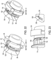
- Fig. 22 is a drawing depicting operation of the positive locking feature of the fitting assembly.
- the nut is omitted for simplicity of illustration.
- Fig. 22 illustrates the configuration of the sleeve 24 in combination with the fluid section 114 and coil spring 26 to provide the positive locking feature.
- the left portion of Fig. 22 illustrates the configuration through operation corresponding through Sections I and II of the torque curve, and the right portion of Fig. 22 illustrates the configuration through operation corresponding through Section III of the torque curve.
- the sleeve includes a contact surface, and the vertical spring leg slides over the contact surface during a portion of nut rotation during which an insufficient torque level is being applied to the nut.
- the sleeve further includes a locking window positioned adjacent to the sliding surface, and when the desired operational torque level is applied to the nut the vertical spring leg is positioned through the locking window to be positioned within a groove of the serrated portion of the nipple fluid section.
- the sleeve 24 includes a contact surface 121 against which the vertical spring leg 120 slides in contact during the Sections I and II operation in which a zero or insufficient torque level is being applied.
- the sleeve 24 also has a locking window 122 through which the vertical spring leg 120 extends during the Section III operation during which the desired operational torque value becomes applied.
- the vertical spring leg 120 is in contact with the contact surface 121 of the sleeve 24, and therefore the positive locking feature is not engaged.
- the sleeve becomes disengaged from the nut, with the sleeve being fixed and immobile and the nut rotating independently relative to the sleeve.
- the coil spring rotates with the nut to become energized.
- the vertical spring leg 120 slides across the contact surface 121 of the stationary sleeve 24.
- the vertical spring leg 120 becomes aligned with the locking window 122, which exposes a portion of the serrated portion 118 of the fluid section 114. Due to the spring bias, the vertical spring leg 120 extends through the locking window 122 to engage with the serrated portion 118 to engage the positive locking feature as the operational torque value is reached.
- an analogous positive lock spring is always engaged with the serration or a flat surface of the attached fluid section.
- the positive locking feature is engaged when approximately 75% of the nominal torque value is reached when tightening the nut, and will be disengaged when the torque value goes below approximately 75% of the nominal torque value when loosening the nut (such as for maintenance and repair).
- the locking window 122 is sized and positioned on the sleeve 24 to have the spring leg engagement/disengagement at approximately 75% of the desired operational torque value.
- the contact surface and the locking window of the sleeve are positioned such that the vertical leg spring slides against the contact surface during nut rotation when the torque level being applied to the nut is approximately 75% of the desired operational torque level or less, and the vertical leg spring extends through the window and moves up and down over the serrated portion of the nipple fluid section when the torque level being applied to the nut is more than approximately 75% of the desired operational torque level.
- Such operation improves the operation of the locking feature to provide effective positive locking while rendering manual nut loosening easier.
- Fig. 23 is a drawing depicting an alternative design of a sleeve 124 for providing an additional or alternative positive locking feature.
- the positive locking feature includes a spring tab of the sleeve that ends in a pawl, and the spring tab moves up and down over the serrated portion of the nipple fluid section such that when the desired operational torque level is being applied to the nut, the pawl is positioned within a groove of the serrated portion to positively lock the position of the nut.
- a sleeve 124 includes a spring tab 126 that ends in a pawl 128.
- the spring tab 126 will rise and fall over the serrations of the serrated portion 118 of the fluid section 114 until the correct operational torque level is reached.
- the pawl 128 then remains locked within one of the serration grooves to enhance the positive locking of the fitting assembly to the fluid section.
- the fitting assembly embodiments of the present disclosure also may be used in combination with electronic torque sensing components.
- an electronic proximity sensor may be used for maximum torque indication or nut loosening and displayed to an electronic display device by a wired or wireless electronic connection.
- An electrical circuit board may be attached to the back side of the sleeve, and the spring pin movement can be measured by a resistance or capacitance change. Such change in resistance or capacitance can be calibrated to a torque value and likewise displayed to an electronic display device by a wired or wireless electronic connection.
Landscapes
- Engineering & Computer Science (AREA)
- General Engineering & Computer Science (AREA)
- Mechanical Engineering (AREA)
- Bolts, Nuts, And Washers (AREA)
- Force Measurement Appropriate To Specific Purposes (AREA)
Claims (15)
- Eine Verschraubungsanordnung (10) zum Koppeln eines ersten Fluidabschnitts (12) an einen zweiten Fluidabschnitt (14), wobei die Verschraubungsanordnung (10) Folgendes beinhaltet:eine Mutter (22) mit einem ersten Ende (32) und einem zweiten Ende (34) gegenüber von dem erste Ende (32);eine Sichtanzeigeranordnung (16), die an dem ersten Ende (32) der Mutter positioniert ist, wobei die Sichtanzeigeranordnung (16) eine Vielzahl von Sichtanzeigern (18, 19, 20) umfasst, die eine Sichtanzeige eines auf die Mutter (22) ausgeübten Drehmomentniveaus bereitstellen;eine Hülse (24), die an der Mutter (22) angebracht ist und ein Fenster (42) umfasst, durch das ein Teil der Vielzahl von Sichtanzeigern (18, 19, 20), basierend auf dem Drehmomentniveau, das auf die Mutter (22) ausgeübt wird, sichtbar ist; undein elastisches Element (26), das die Hülse (24) an die Mutter (22) koppelt;wobei, wenn die Mutter (22) gedreht wird, um Drehmoment auf die Mutter auszuüben, um dadurch den ersten Fluidabschnitt (12) an den zweiten Fluidabschnitt (14) zu koppeln, das elastische Element (26) die Hülse (24) in eine ortsfeste Stellung drückt und sich die Mutter (22) relativ zu der Hülse (24) dreht, wodurch sich die Sichtanzeigeranordnung (16) relativ zu der Hülse (24) dreht, um zu ändern, welcher Teil der Sichtanzeigeranordnung (16) durch das Fenster (42) sichtbar ist, um eine Sichtanzeige darüber bereitzustellen, wann das auf die Mutter (22) ausgeübte Drehmomentniveau ein gewünschtes Betriebsdrehmomentniveau ist.
- Verschraubungsanordnung (10) gemäß Anspruch 1, wobei die Hülse (24) einen Teleskopteil (39), der in die Mutter (22) eingesteckt positioniert ist, und einen Abdeckungsteil (40), der sich um und über das erste Ende (32) der Mutter und die Sichtanzeigeranordnung (16) erstreckend positioniert ist, beinhaltet.
- Verschraubungsanordnung (10) gemäß einem der Ansprüche 1-2, wobei das elastische Element (26) eine Spiralfeder ist, die ein erstes Ende, das als Federschenkel (48), der in eine in der Mutter gebildete Federnut (36) eingesteckt positioniert ist, konfiguriert ist, und ein zweites Ende, das an der Hülse (24) anliegend positioniert ist, aufweist.
- Verschraubungsanordnung (10) gemäß einem der Ansprüche 1-3, ferner beinhaltend einen Federstift (38), der aus einer ausgefahrenen Stellung, die einem Null-Drehmomentzustand des auf die Mutter (22) ausgeübten Drehmomentniveaus entspricht, in eine eingezogene Stellung, die einem Nicht-Null-Drehmomentzustand des auf die Mutter ausgeübten Drehmomentniveaus entspricht, konfigurierbar ist;
wobei in der ausgefahrenen Stellung der Federstift (38) die Hülse (24) an die Mutter (22) koppelt, sodass sich die Hülse (24) und die Mutter (22) miteinander drehen, und in der eingezogenen Stellung der die Hülse (24) an die Mutter (22) koppelnde Federstift (38) gelöst ist, sodass sich die Mutter (22) relativ zu der Hülse (24) dreht. - Verschraubungsanordnung (10) gemäß Anspruch 4, wobei der Federstift (38) eine von der Mutter (22) und der Hülse (24) separate Komponente ist und
wobei in der ausgefahrenen Stellung der Federstift (38) in einem Mutterstiftloch (54) in der Mutter positioniert ist und sich durch ein Hülsenstiftloch (44) in der Hülse erstreckt, um die Hülse (24) an die Mutter (22) zu koppeln, und in der eingezogenen Stellung sich der Federstift (38) nicht durch das Hülsenstiftloch (44) erstreckt, um die Mutter (22) von der Hülse (24) zu lösen. - Verschraubungsanordnung (10) gemäß einem der Ansprüche 4-5, ferner beinhaltend einen Klanganzeiger, der einen an einer inneren Oberfläche (62) der Hülse (24) befestigten Vorsprung (60) umfasst, wobei, wenn sich die Mutter (22) relativ zu der Hülse (24) dreht, der Federstift (38) mit dem Vorsprung (60) in Kontakt kommt, um eine Klanganzeige darüber bereitzustellen, wann das gewünschte Betriebsdrehmomentniveau auf die Mutter (22) ausgeübt wird.
- Verschraubungsanordnung (10) gemäß Anspruch 4, wobei der Federstift (64) als Biegung in einer Oberfläche der Hülse (24b) konfiguriert ist und
wobei in der ausgefahrenen Stellung der Federstift (64) in einem Mutterstiftloch (66) in der Mutter positioniert ist, um die Hülse (24) an die Mutter (22) zu koppeln, und in der eingezogenen Stellung sich der Federstift (64) nicht in das Mutterstiftloch (66) erstreckt, um die Mutter (22) von der Hülse (24) zu lösen. - Verschraubungsanordnung (10) gemäß einem der Ansprüche 1-7, wobei die Sichtanzeigeranordnung (16) einen ersten Sichtanzeiger (18), der anzeigt, dass ein ungenügendes Drehmomentniveau auf die Mutter (22) ausgeübt wird, und einen von dem ersten Sichtanzeiger (18) verschiedenen zweiten Sichtanzeiger (20), der anzeigt, dass das gewünschte Betriebsdrehmomentniveau auf die Mutter (22) ausgeübt wird, beinhaltet.
- Verschraubungsanordnung (10) gemäß Anspruch 8, wobei die Sichtanzeigeranordnung (16) ferner einen mittleren Sichtanzeiger (19) beinhaltet, der von dem ersten Sichtanzeiger (18) und dem zweiten Sichtanzeiger (20) verschieden und zwischen diesen angeordnet ist; und
wobei der erste Sichtanzeiger (18) angibt, dass ein Null-Drehmomentniveau auf die Mutter (22) ausgeübt wird, der mittlere Sichtanzeiger (19) angibt, dass ein Nicht-Null- aber ungenügendes Drehmomentniveau auf die Mutter (22) ausgeübt wird, und der zweite Sichtanzeiger (20) angibt, dass das gewünschte Betriebsdrehmomentniveau auf die Mutter (22) ausgeübt wird. - Verschraubungsanordnung (10) gemäß einem der Ansprüche 8-9, wobei die Sichtanzeigeranordnung (16c) ferner eine Vielzahl von verschiedenen Drehmomentniveaus entsprechenden Drehmomentniveaumarkierungen (68) beinhaltet und die Hülse (24c) ferner einen in dem Fenster (42c) positionierten Zeiger (70) beinhaltet, der auf eine einem auf die Mutter (22) ausgeübten Drehmomentniveau entsprechende der Vielzahl von Drehmomentniveaumarkierungen (68) zeigt.
- Eine Fluidverbindungsanordnung, die Folgendes beinhaltet:die Verschraubungsanordnung (10) gemäß einem der Ansprüche 1-10; undeinen Stutzenfluidabschnitt (114), der über das erste Ende der Mutter (32) mit der Mutter (22) verbunden ist;wobei die Stutzenfluidverbindung (114) eine äußere Oberfläche mit einem gezahnten Teil (118) umfasst und die Verschraubungsanordnung (10) ein Merkmal (26) zur formschlüssigen Arretierung umfasst, das mit dem gezahnten Teil (118) der Stutzenfluidverbindung in Wechselwirkung steht, um eine Stellung der Mutter (22) formschlüssig zu arretieren, um ein Lockern der Mutter während des Gebrauchs zu verhindern.
- Fluidverbindungsanordnung gemäß Anspruch 11, wobei das Merkmal zur formschlüssigen Arretierung einen vertikalen Federschenkel (120) des elastischen Elements (26) beinhaltet und der vertikale Federschenkel (120) dazu konfiguriert ist, sich über den gezahnten Teil (118) des Stutzenfluidabschnitts auf und ab zu bewegen, sodass, wenn das gewünschte Betriebsdrehmomentniveau auf die Mutter (22) ausgeübt wird, der vertikale Federschenkel (120) in einer Nut des gezahnten Teils (118) positioniert ist, um die Stellung der Mutter (22) formschlüssig zu arretieren.
- Fluidverbindungsanordnung gemäß Anspruch 12, wobei die Hülse (24) eine Kontaktoberfläche (121) umfasst und der vertikale Federschenkel (120) dazu konfiguriert ist, während eines Teils der Mutterdrehung, während dessen ein ungenügendes Drehmomentniveau auf die Mutter (22) ausgeübt wird, über die Kontaktoberfläche (121) zu gleiten; und
wobei die Hülse (24) ferner ein der Kontaktfläche (121) benachbart positioniertes Arretierungsfenster (122) umfasst und, wenn das gewünschte Betriebsdrehmomentniveau auf die Mutter ausgeübt wird, der vertikale Federschenkel (120) durch das Arretierungsfenster (122) hindurch positioniert ist, um in der Nut des gezahnten Teils (188) des Stutzenfluidabschnitts positioniert zu sein. - Fluidverbindungsanordnung gemäß Anspruch 13, wobei die Kontaktoberfläche (121) und das Arretierungsfenster (122) der Hülse derart positioniert sind, dass die vertikale Schenkelfeder (120) während der Mutterdrehung an der Kontaktoberfläche (121) gleitet, wenn das auf die Mutter ausgeübte Drehmomentniveau 75 % des gewünschten Betriebsdrehmomentniveaus oder weniger beträgt, und sich die vertikale Schenkelfeder (120) durch das Fenster (42) hindurch erstreckt und sich über den gezahnten Teil (118) des Stutzenfluidabschnitts auf und ab bewegt, wenn das auf die Mutter ausgeübte Drehmomentniveau mehr als 75 % des gewünschten Betriebsdrehmomentniveaus beträgt.
- Fluidverbindungsanordnung gemäß Anspruch 11-14, wobei das Merkmal zur formschlüssigen Arretierung eine Federlasche (126) der Hülse (124) beinhaltet, die in einer Klaue (128) endet, und die Federlasche (126) dazu konfiguriert ist, sich über den gezahnten Teil (118) des Stutzenfluidabschnitts auf und ab zu bewegen, sodass, wenn das gewünschte Betriebsdrehmomentniveau auf die Mutter (22) ausgeübt wird, die Klaue (128) in einer Nut des gezahnten Teils (118) positioniert ist, um die Stellung der Mutter (22) formschlüssig zu arretieren.
Applications Claiming Priority (1)
| Application Number | Priority Date | Filing Date | Title |
|---|---|---|---|
| US202163234722P | 2021-08-19 | 2021-08-19 |
Publications (2)
| Publication Number | Publication Date |
|---|---|
| EP4137731A1 EP4137731A1 (de) | 2023-02-22 |
| EP4137731B1 true EP4137731B1 (de) | 2024-11-27 |
Family
ID=82838939
Family Applications (1)
| Application Number | Title | Priority Date | Filing Date |
|---|---|---|---|
| EP22188855.5A Active EP4137731B1 (de) | 2021-08-19 | 2022-08-04 | Universeller drehmomentanzeigeradapter mit formschlüssiger verriegelungsfunktion |
Country Status (3)
| Country | Link |
|---|---|
| US (1) | US11933339B2 (de) |
| EP (1) | EP4137731B1 (de) |
| ES (1) | ES3001194T3 (de) |
Families Citing this family (2)
| Publication number | Priority date | Publication date | Assignee | Title |
|---|---|---|---|---|
| JP2023067563A (ja) * | 2021-11-01 | 2023-05-16 | 日本サーモスタット株式会社 | 循環回路部材、及び循環回路部材の製造方法 |
| AT527227B1 (de) * | 2024-01-30 | 2024-12-15 | Gitterle Andreas | Verbindungselement für schläuche, rohre oder andere fluidtransporteinrichtungen |
Family Cites Families (14)
| Publication number | Priority date | Publication date | Assignee | Title |
|---|---|---|---|---|
| US5280967A (en) * | 1992-03-27 | 1994-01-25 | Donald Travis | Device for indicating the proper installation of fittings |
| AU4808800A (en) | 1999-04-30 | 2000-11-17 | Crane-Resistoflex | Nut locking apparatus |
| US6409222B1 (en) * | 2000-06-08 | 2002-06-25 | Fluroware, Inc. | Torque confirmation fitting |
| US6694827B2 (en) | 2000-07-21 | 2004-02-24 | Crane-Resistoflex Company | Fluid coupling with a torque indication device |
| DE10238752B4 (de) | 2002-08-23 | 2010-09-09 | Andreas Stihl Ag & Co. | Einrichtung zum Abfüllen von Flüssigkeiten |
| US7156424B2 (en) | 2004-03-05 | 2007-01-02 | Parker-Hannifin Corporation | Coupling assembly with retention mechanism |
| EP2501975B1 (de) * | 2009-11-20 | 2015-01-07 | Alcoa Inc. | Verdrehsicheres Fitting ohne Sicherungsdraht |
| JP5360619B2 (ja) | 2011-12-12 | 2013-12-04 | Smc株式会社 | 管継手 |
| WO2015187958A1 (en) | 2014-06-04 | 2015-12-10 | Parker-Hannifin Corporation | Compression fitting with torque nut |
| US10704975B2 (en) * | 2018-03-09 | 2020-07-07 | General Electric Company | Visual torque indication for threaded joints |
| CA3107725C (en) * | 2018-09-13 | 2023-10-10 | Jpb Systeme | Fluid-tight fitting |
| CN114222881B (zh) * | 2019-06-13 | 2024-03-08 | 帕克-汉尼芬公司 | 用于将流体输送管道互连的螺纹联接组件 |
| US11530762B2 (en) * | 2019-11-05 | 2022-12-20 | The Boeing Company | Coupling nut visible tightness indicator |
| US11698153B2 (en) * | 2021-09-24 | 2023-07-11 | Caterpillar Inc. | Fluid joint assembly adjustable from primary to backup sealing state and fluid connector for same |
-
2022
- 2022-08-01 US US17/878,117 patent/US11933339B2/en active Active
- 2022-08-04 EP EP22188855.5A patent/EP4137731B1/de active Active
- 2022-08-04 ES ES22188855T patent/ES3001194T3/es active Active
Also Published As
| Publication number | Publication date |
|---|---|
| US11933339B2 (en) | 2024-03-19 |
| ES3001194T3 (es) | 2025-03-04 |
| US20230056893A1 (en) | 2023-02-23 |
| EP4137731A1 (de) | 2023-02-22 |
Similar Documents
| Publication | Publication Date | Title |
|---|---|---|
| EP4137731B1 (de) | Universeller drehmomentanzeigeradapter mit formschlüssiger verriegelungsfunktion | |
| US8210783B2 (en) | Threaded fastener with predetermined torque | |
| JP4619723B2 (ja) | 雌取付けアセンブリおよび継手アセンブリ | |
| JP2509066B2 (ja) | 流体継手、及び流体継手の流体密封をなす方法 | |
| EP0316417B1 (de) | Befestigungsvorrichtung | |
| CN110242804B (zh) | 用于螺纹接头的视觉扭矩指示 | |
| US20070164566A1 (en) | Lockwireless coupling assembly | |
| CA2442357A1 (en) | Threaded connection | |
| US5232249A (en) | Fastening device | |
| US9556894B2 (en) | Tie bolt employing differential thread | |
| KR20180096488A (ko) | 억지 끼워맞춤 패스너들을 위한 반경형 인입부 | |
| US8961063B2 (en) | Hub clamp assembly | |
| JPS58106222A (ja) | 同軸の部品を固定連結するための継手及びそのカルダン軸における使用方法 | |
| CA3084477A1 (en) | Fastener systems and methods | |
| PL204872B1 (pl) | Złączka hydrauliczna węża i sposób wytwarzania złączki hydraulicznej węża | |
| US9945413B2 (en) | Locking fastener | |
| US8544366B2 (en) | Spark plug removal tool apparatus | |
| EP4067718B1 (de) | Dichtungsvorrichtung für bohrungen eines wärmetauschers | |
| EP4660502A1 (de) | Verbindungsmechanismus für stahlrohr und verbindung | |
| US20110044783A1 (en) | Retainer Apparatus | |
| CN120225804A (zh) | 旨在连接到第二管道的改进的管状组件 | |
| WO2008040977A1 (en) | Threaded fastener with predetermined torque |
Legal Events
| Date | Code | Title | Description |
|---|---|---|---|
| PUAI | Public reference made under article 153(3) epc to a published international application that has entered the european phase |
Free format text: ORIGINAL CODE: 0009012 |
|
| STAA | Information on the status of an ep patent application or granted ep patent |
Free format text: STATUS: THE APPLICATION HAS BEEN PUBLISHED |
|
| AK | Designated contracting states |
Kind code of ref document: A1 Designated state(s): AL AT BE BG CH CY CZ DE DK EE ES FI FR GB GR HR HU IE IS IT LI LT LU LV MC MK MT NL NO PL PT RO RS SE SI SK SM TR |
|
| STAA | Information on the status of an ep patent application or granted ep patent |
Free format text: STATUS: REQUEST FOR EXAMINATION WAS MADE |
|
| P01 | Opt-out of the competence of the unified patent court (upc) registered |
Effective date: 20230524 |
|
| 17P | Request for examination filed |
Effective date: 20230602 |
|
| RBV | Designated contracting states (corrected) |
Designated state(s): AL AT BE BG CH CY CZ DE DK EE ES FI FR GB GR HR HU IE IS IT LI LT LU LV MC MK MT NL NO PL PT RO RS SE SI SK SM TR |
|
| GRAP | Despatch of communication of intention to grant a patent |
Free format text: ORIGINAL CODE: EPIDOSNIGR1 |
|
| STAA | Information on the status of an ep patent application or granted ep patent |
Free format text: STATUS: GRANT OF PATENT IS INTENDED |
|
| RIC1 | Information provided on ipc code assigned before grant |
Ipc: F16B 21/18 20060101ALI20240806BHEP Ipc: F16B 7/18 20060101ALI20240806BHEP Ipc: F16B 7/04 20060101ALI20240806BHEP Ipc: F16B 31/02 20060101ALI20240806BHEP Ipc: F16B 1/00 20060101ALI20240806BHEP Ipc: F16L 19/025 20060101AFI20240806BHEP |
|
| INTG | Intention to grant announced |
Effective date: 20240822 |
|
| GRAS | Grant fee paid |
Free format text: ORIGINAL CODE: EPIDOSNIGR3 |
|
| GRAA | (expected) grant |
Free format text: ORIGINAL CODE: 0009210 |
|
| STAA | Information on the status of an ep patent application or granted ep patent |
Free format text: STATUS: THE PATENT HAS BEEN GRANTED |
|
| AK | Designated contracting states |
Kind code of ref document: B1 Designated state(s): AL AT BE BG CH CY CZ DE DK EE ES FI FR GB GR HR HU IE IS IT LI LT LU LV MC MK MT NL NO PL PT RO RS SE SI SK SM TR |
|
| REG | Reference to a national code |
Ref country code: GB Ref legal event code: FG4D |
|
| REG | Reference to a national code |
Ref country code: CH Ref legal event code: EP |
|
| REG | Reference to a national code |
Ref country code: DE Ref legal event code: R096 Ref document number: 602022008120 Country of ref document: DE |
|
| REG | Reference to a national code |
Ref country code: IE Ref legal event code: FG4D |
|
| REG | Reference to a national code |
Ref country code: ES Ref legal event code: FG2A Ref document number: 3001194 Country of ref document: ES Kind code of ref document: T3 Effective date: 20250304 |
|
| REG | Reference to a national code |
Ref country code: LT Ref legal event code: MG9D |
|
| REG | Reference to a national code |
Ref country code: NL Ref legal event code: MP Effective date: 20241127 |
|
| PG25 | Lapsed in a contracting state [announced via postgrant information from national office to epo] |
Ref country code: IS Free format text: LAPSE BECAUSE OF FAILURE TO SUBMIT A TRANSLATION OF THE DESCRIPTION OR TO PAY THE FEE WITHIN THE PRESCRIBED TIME-LIMIT Effective date: 20250327 Ref country code: HR Free format text: LAPSE BECAUSE OF FAILURE TO SUBMIT A TRANSLATION OF THE DESCRIPTION OR TO PAY THE FEE WITHIN THE PRESCRIBED TIME-LIMIT Effective date: 20241127 Ref country code: PT Free format text: LAPSE BECAUSE OF FAILURE TO SUBMIT A TRANSLATION OF THE DESCRIPTION OR TO PAY THE FEE WITHIN THE PRESCRIBED TIME-LIMIT Effective date: 20250327 |
|
| PG25 | Lapsed in a contracting state [announced via postgrant information from national office to epo] |
Ref country code: FI Free format text: LAPSE BECAUSE OF FAILURE TO SUBMIT A TRANSLATION OF THE DESCRIPTION OR TO PAY THE FEE WITHIN THE PRESCRIBED TIME-LIMIT Effective date: 20241127 Ref country code: NL Free format text: LAPSE BECAUSE OF FAILURE TO SUBMIT A TRANSLATION OF THE DESCRIPTION OR TO PAY THE FEE WITHIN THE PRESCRIBED TIME-LIMIT Effective date: 20241127 |
|
| REG | Reference to a national code |
Ref country code: AT Ref legal event code: MK05 Ref document number: 1746011 Country of ref document: AT Kind code of ref document: T Effective date: 20241127 |
|
| PG25 | Lapsed in a contracting state [announced via postgrant information from national office to epo] |
Ref country code: BG Free format text: LAPSE BECAUSE OF FAILURE TO SUBMIT A TRANSLATION OF THE DESCRIPTION OR TO PAY THE FEE WITHIN THE PRESCRIBED TIME-LIMIT Effective date: 20241127 |
|
| PG25 | Lapsed in a contracting state [announced via postgrant information from national office to epo] |
Ref country code: NO Free format text: LAPSE BECAUSE OF FAILURE TO SUBMIT A TRANSLATION OF THE DESCRIPTION OR TO PAY THE FEE WITHIN THE PRESCRIBED TIME-LIMIT Effective date: 20250227 |
|
| PG25 | Lapsed in a contracting state [announced via postgrant information from national office to epo] |
Ref country code: LV Free format text: LAPSE BECAUSE OF FAILURE TO SUBMIT A TRANSLATION OF THE DESCRIPTION OR TO PAY THE FEE WITHIN THE PRESCRIBED TIME-LIMIT Effective date: 20241127 Ref country code: GR Free format text: LAPSE BECAUSE OF FAILURE TO SUBMIT A TRANSLATION OF THE DESCRIPTION OR TO PAY THE FEE WITHIN THE PRESCRIBED TIME-LIMIT Effective date: 20250228 Ref country code: AT Free format text: LAPSE BECAUSE OF FAILURE TO SUBMIT A TRANSLATION OF THE DESCRIPTION OR TO PAY THE FEE WITHIN THE PRESCRIBED TIME-LIMIT Effective date: 20241127 |
|
| PG25 | Lapsed in a contracting state [announced via postgrant information from national office to epo] |
Ref country code: PL Free format text: LAPSE BECAUSE OF FAILURE TO SUBMIT A TRANSLATION OF THE DESCRIPTION OR TO PAY THE FEE WITHIN THE PRESCRIBED TIME-LIMIT Effective date: 20241127 |
|
| PG25 | Lapsed in a contracting state [announced via postgrant information from national office to epo] |
Ref country code: RS Free format text: LAPSE BECAUSE OF FAILURE TO SUBMIT A TRANSLATION OF THE DESCRIPTION OR TO PAY THE FEE WITHIN THE PRESCRIBED TIME-LIMIT Effective date: 20250227 |
|
| PG25 | Lapsed in a contracting state [announced via postgrant information from national office to epo] |
Ref country code: SM Free format text: LAPSE BECAUSE OF FAILURE TO SUBMIT A TRANSLATION OF THE DESCRIPTION OR TO PAY THE FEE WITHIN THE PRESCRIBED TIME-LIMIT Effective date: 20241127 |
|
| PG25 | Lapsed in a contracting state [announced via postgrant information from national office to epo] |
Ref country code: DK Free format text: LAPSE BECAUSE OF FAILURE TO SUBMIT A TRANSLATION OF THE DESCRIPTION OR TO PAY THE FEE WITHIN THE PRESCRIBED TIME-LIMIT Effective date: 20241127 |
|
| PG25 | Lapsed in a contracting state [announced via postgrant information from national office to epo] |
Ref country code: EE Free format text: LAPSE BECAUSE OF FAILURE TO SUBMIT A TRANSLATION OF THE DESCRIPTION OR TO PAY THE FEE WITHIN THE PRESCRIBED TIME-LIMIT Effective date: 20241127 |
|
| PG25 | Lapsed in a contracting state [announced via postgrant information from national office to epo] |
Ref country code: RO Free format text: LAPSE BECAUSE OF FAILURE TO SUBMIT A TRANSLATION OF THE DESCRIPTION OR TO PAY THE FEE WITHIN THE PRESCRIBED TIME-LIMIT Effective date: 20241127 |
|
| PG25 | Lapsed in a contracting state [announced via postgrant information from national office to epo] |
Ref country code: SK Free format text: LAPSE BECAUSE OF FAILURE TO SUBMIT A TRANSLATION OF THE DESCRIPTION OR TO PAY THE FEE WITHIN THE PRESCRIBED TIME-LIMIT Effective date: 20241127 |
|
| PG25 | Lapsed in a contracting state [announced via postgrant information from national office to epo] |
Ref country code: CZ Free format text: LAPSE BECAUSE OF FAILURE TO SUBMIT A TRANSLATION OF THE DESCRIPTION OR TO PAY THE FEE WITHIN THE PRESCRIBED TIME-LIMIT Effective date: 20241127 |
|
| REG | Reference to a national code |
Ref country code: DE Ref legal event code: R097 Ref document number: 602022008120 Country of ref document: DE |
|
| PG25 | Lapsed in a contracting state [announced via postgrant information from national office to epo] |
Ref country code: SE Free format text: LAPSE BECAUSE OF FAILURE TO SUBMIT A TRANSLATION OF THE DESCRIPTION OR TO PAY THE FEE WITHIN THE PRESCRIBED TIME-LIMIT Effective date: 20241127 |
|
| PLBE | No opposition filed within time limit |
Free format text: ORIGINAL CODE: 0009261 |
|
| STAA | Information on the status of an ep patent application or granted ep patent |
Free format text: STATUS: NO OPPOSITION FILED WITHIN TIME LIMIT |
|
| REG | Reference to a national code |
Ref country code: CH Ref legal event code: L10 Free format text: ST27 STATUS EVENT CODE: U-0-0-L10-L00 (AS PROVIDED BY THE NATIONAL OFFICE) Effective date: 20251008 |
|
| PGFP | Annual fee paid to national office [announced via postgrant information from national office to epo] |
Ref country code: ES Payment date: 20250901 Year of fee payment: 4 |
|
| PGFP | Annual fee paid to national office [announced via postgrant information from national office to epo] |
Ref country code: DE Payment date: 20250827 Year of fee payment: 4 |
|
| PGFP | Annual fee paid to national office [announced via postgrant information from national office to epo] |
Ref country code: IT Payment date: 20250901 Year of fee payment: 4 |
|
| PGFP | Annual fee paid to national office [announced via postgrant information from national office to epo] |
Ref country code: FR Payment date: 20250825 Year of fee payment: 4 |
|
| 26N | No opposition filed |
Effective date: 20250828 |
|
| REG | Reference to a national code |
Ref country code: CH Ref legal event code: H13 Free format text: ST27 STATUS EVENT CODE: U-0-0-H10-H13 (AS PROVIDED BY THE NATIONAL OFFICE) Effective date: 20260324 |
|
| PG25 | Lapsed in a contracting state [announced via postgrant information from national office to epo] |
Ref country code: MC Free format text: LAPSE BECAUSE OF FAILURE TO SUBMIT A TRANSLATION OF THE DESCRIPTION OR TO PAY THE FEE WITHIN THE PRESCRIBED TIME-LIMIT Effective date: 20241127 |
|
| PG25 | Lapsed in a contracting state [announced via postgrant information from national office to epo] |
Ref country code: LU Free format text: LAPSE BECAUSE OF NON-PAYMENT OF DUE FEES Effective date: 20250804 |
|
| PG25 | Lapsed in a contracting state [announced via postgrant information from national office to epo] |
Ref country code: CH Free format text: LAPSE BECAUSE OF NON-PAYMENT OF DUE FEES Effective date: 20250831 |