EP4137732B1 - Schnellverbinder mit prüfer - Google Patents
Schnellverbinder mit prüfer Download PDFInfo
- Publication number
- EP4137732B1 EP4137732B1 EP22190762.9A EP22190762A EP4137732B1 EP 4137732 B1 EP4137732 B1 EP 4137732B1 EP 22190762 A EP22190762 A EP 22190762A EP 4137732 B1 EP4137732 B1 EP 4137732B1
- Authority
- EP
- European Patent Office
- Prior art keywords
- verifier
- socket
- opening
- extending
- fluid tube
- Prior art date
- Legal status (The legal status is an assumption and is not a legal conclusion. Google has not performed a legal analysis and makes no representation as to the accuracy of the status listed.)
- Active
Links
Images


Classifications
-
- F—MECHANICAL ENGINEERING; LIGHTING; HEATING; WEAPONS; BLASTING
- F16—ENGINEERING ELEMENTS AND UNITS; GENERAL MEASURES FOR PRODUCING AND MAINTAINING EFFECTIVE FUNCTIONING OF MACHINES OR INSTALLATIONS; THERMAL INSULATION IN GENERAL
- F16L—PIPES; JOINTS OR FITTINGS FOR PIPES; SUPPORTS FOR PIPES, CABLES OR PROTECTIVE TUBING; MEANS FOR THERMAL INSULATION IN GENERAL
- F16L37/00—Couplings of the quick-acting type
- F16L37/08—Couplings of the quick-acting type in which the connection between abutting or axially overlapping ends is maintained by locking members
- F16L37/12—Couplings of the quick-acting type in which the connection between abutting or axially overlapping ends is maintained by locking members using hooks, pawls, or other movable or insertable locking members
- F16L37/1225—Couplings of the quick-acting type in which the connection between abutting or axially overlapping ends is maintained by locking members using hooks, pawls, or other movable or insertable locking members using a retaining member the extremities of which, e.g. in the form of a U, engage behind a shoulder of both parts
-
- F—MECHANICAL ENGINEERING; LIGHTING; HEATING; WEAPONS; BLASTING
- F16—ENGINEERING ELEMENTS AND UNITS; GENERAL MEASURES FOR PRODUCING AND MAINTAINING EFFECTIVE FUNCTIONING OF MACHINES OR INSTALLATIONS; THERMAL INSULATION IN GENERAL
- F16L—PIPES; JOINTS OR FITTINGS FOR PIPES; SUPPORTS FOR PIPES, CABLES OR PROTECTIVE TUBING; MEANS FOR THERMAL INSULATION IN GENERAL
- F16L37/00—Couplings of the quick-acting type
- F16L37/08—Couplings of the quick-acting type in which the connection between abutting or axially overlapping ends is maintained by locking members
- F16L37/084—Couplings of the quick-acting type in which the connection between abutting or axially overlapping ends is maintained by locking members combined with automatic locking
- F16L37/088—Couplings of the quick-acting type in which the connection between abutting or axially overlapping ends is maintained by locking members combined with automatic locking by means of a split elastic ring
- F16L37/0885—Couplings of the quick-acting type in which the connection between abutting or axially overlapping ends is maintained by locking members combined with automatic locking by means of a split elastic ring with access to the split elastic ring from a radial or tangential opening in the coupling
-
- F—MECHANICAL ENGINEERING; LIGHTING; HEATING; WEAPONS; BLASTING
- F16—ENGINEERING ELEMENTS AND UNITS; GENERAL MEASURES FOR PRODUCING AND MAINTAINING EFFECTIVE FUNCTIONING OF MACHINES OR INSTALLATIONS; THERMAL INSULATION IN GENERAL
- F16L—PIPES; JOINTS OR FITTINGS FOR PIPES; SUPPORTS FOR PIPES, CABLES OR PROTECTIVE TUBING; MEANS FOR THERMAL INSULATION IN GENERAL
- F16L2201/00—Special arrangements for pipe couplings
- F16L2201/10—Indicators for correct coupling
Definitions
- the field relates to fluid connectors. More particularly, this disclosure relates to a quick connector with a verifier that visually indicates a correct fluid connection.
- Quick connectors find use in the automotive and other industries for coupling fluid piping.
- a tube is joined to another device such as a pump, tank, or another tube.
- the quick connector may have a tubular female receptacle body arranged to sealingly receive a male tube therein.
- the male tube may include an endform adapted to make a snap engagement with the female receptacle body and provide a locking relationship between the endform and the female receptacle body.
- Use of quick connectors is advantageous in that a sealed and secured fluid line may be established with a minimum amount of time and expense.
- US 10 816 121 B2 , US 2016/069496 A1 , EP 3 521 676 A2 and DE 20 2020 103903 U1 each disclose examples of such quick connectors.
- a first embodiment of this disclosure provides a quick connector assembly that couples a fluid line between a first and a second fluid tube.
- the quick connector assembly comprises a receptacle body having a cavity extending through the receptacle body to a stem portion connected to the second fluid tube.
- a sealing section is located within the cavity and a socket portion extends from the sealing section.
- the socket portion includes a wall bordering a socket opening in alignment with the cavity.
- a pair of latch openings extend through a portion of the wall into the socket opening.
- a sealing member having a receiver opening is installed in the sealing section with the receiver opening in alignment with the socket opening and the stem portion.
- a bracket is installed on the wall and includes a pair of spring latches with each spring latch extending through a respective one of the pair of the latch openings into the socket opening.
- a first fluid tube having an insertion portion and a raised upset has the insertion portion placed through the socket opening into the receiver opening making a fluid connection to the second fluid tube and causing the upset to be captured by each spring latch retaining the first fluid tube to the receptacle body.
- a process for forming a coupling in a fluid line between a first and second fluid tube comprises, coupling the second fluid tube to a stem of a receptacle body that has a cavity extending through the receptacle body.
- a sealing member having a receiver opening in alignment with the socket opening and the stem portion is installed in a sealing section formed within the cavity.
- a socket portion extends from the sealing section that includes a wall bordering a socket opening in alignment with the receiver opening.
- a pair of latch openings extend through a portion of the wall into the socket opening and a bracket is installed on the wall that includes a pair of spring latches with each spring latch extending through a respective one of the pair of the latch openings into the socket opening.
- the process further includes forming an endform on the first fluid tube including an insertion portion and a raised upset and inserting the insertion portion through the socket opening into the receiver opening wherein the first fluid tube makes a fluid coupling to the second fluid tube and causing the upset to be captured by each spring latch and retaining the first fluid tube to the receptacle body.
- a verifier is used in both the first and second embodiments to verify the coupling of the first fluid tube to the receptacle body.
- the verifier includes fixing fingers and a pair of arms. Each arm extends from either side of a push surface.
- the verifier arms and fixing fingers are installed through respective recesses in the wall into the socket opening.
- a force applied to the verifier push surface causes each verifier arm to travel along the sides of the first fluid tube upset to rest below a respective spring latch and the fixing fingers to capture the first fluid tube upset.
- Verifier symbols located on a surface on each verifier arm are visible through the latch openings verifying the coupling of the first fluid tube to the receptacle body.
- each verifier arm further includes a billboard member having verifier symbols located on a billboard surface, wherein each billboard surface is visible through a respective latch opening when each verifier arm extends fully into the socket cavity, verifying the coupling of the first fluid tube to the receptacle body.
- the verifier is placed in an installed condition by applying a force to the verifier push surface.
- FIG. 1 An exploded view of an example quick connector assembly 10 for coupling a fluid line to another fluid line, is illustrated in FIG. 1 .
- the quick connector assembly 10 is used to form a fluid connection in a fluid line between a first fluid tube 12 and a second fluid tube (not shown) installed on a stem 25 of a receptacle body 20.
- the first fluid tube 12 may be a pipe, a hose, or any other fluid conveying component.
- the first fluid tube 12 includes an endform 14 of a tubular configuration arranged to be accepted within a complementary female socket portion 27 of the receptacle body 20 and along generally a longitudinal axis A about which the quick connector 10 is arranged.
- the endform 14 includes a cylindrical insertion portion 15 and a raised upset 18.
- the raised upset 18 extending circumferentially about the exterior of endform 14.
- the upset 18 may be formed integrally from the material of the endform 14 during its manufacture or may be a separate component bonded to the exterior of endform 14.
- the quick connector assembly 10 of the present disclosure further includes a sealing member 30, a bracket 50, and a verifier 80.
- the receptacle body 20 is a tubular member defining a male end that forms the stem 25.
- Stem 25 extends axially from a female end or socket portion 27.
- the stem 25 generally includes various ribs, ridges, and grooves 90 for coupling to the interior cavity of the second fluid tube.
- the various ribs, ridges, and grooves 90 of stem 25 may take several configurations depending on the structure of the second fluid tube attached over stem 25.
- the socket portion 27 is structured for accepting therein a sealing member 30 through an internal cavity 29, shown on FIG. 2 .
- the cavity 29 extends from the socket portion 27 through stem 25 and forms a portion of the fluid line.
- the quick connector 10 further includes a sealing member 30, a bracket 50, and a verifier 80.
- FIGS. 1-3 illustrate an example of a sealing member 30 of the present disclosure and its installation into receptacle body 20.
- the sealing member 30 has a cylindrical outer diameter that is complementary to a cylindrical inner diameter of cavity 29 at a sealing section 28 of the socket portion 27.
- the socket portion 27 is generally D-shaped in configuration and has a socket opening 74 leading into the internal cavity 29.
- the entrance to the sealing section 28 extends from the annular abutment surface 21 to an annular end stop surface 23 having a cylindrical internal wall 22 therebetween.
- the sealing member 30 is comprised of a cylindrical body 31 having a receiver opening 39 extending through the sealing member 30.
- the receiver opening 39 has an inner cylindrical diameter that matches the outer cylindrical diameter of the insertion portion 15 of endform 14.
- the body 31 has an outer cylindrical diameter that allows the outer surface 32 of body 31 to be housed internally within the sealing section 28.
- the sealing member 30 further includes an annular flange 37 on a first end 38 of the body 31.
- the flange 37 extends outward from the body 31 and includes a front planar face 33 and an annular shoulder 36.
- a second end 40 of the sealing member 30 includes a pair of channels 41 extending about the body 31 separated by a spacer ring 42.
- the spacer ring 42 has outer diameter that is substantially similar to the diameter of body 31. Inner portions of each channel 41 opens into receiver opening 39. A pair of elastomeric seals, such as for example, O-rings 43 are arranged to be installed in each channel 41. Portions of each O-ring 43 extend through the opening in each channel 41 and into receiver opening 39.
- the body 31 further includes a pair of windows 45 located in opposition to each other extending through the body 31 to receiver opening 39.
- An L-shaped sealing member latch 46 extends from each window 45.
- the sealing member latches 46 include a first leg 47 extending from the body member surface 32 from each window 45 and a second leg 48 extending perpendicularly from the first leg 47, the second leg 48 extending outward from each window 45.
- the sealing member 30 is installed into socket portion 27 and press-fit into the sealing section 28 by aligning sealing member latches 46 with sealing section openings 24 extending through the sealing section 28 and pushing the sealing member axially into cavity 29 until shoulder 36 rests on abutment surface 21 and the second end 40 contacts stop surface 23.
- each second leg 48 of each latch 46 is deflected and urged inward by the abutment surface 21. As can be best seen in FIG.
- the second leg of latches 46 travel across surface 22 of the sealing section until they reach a respective sealing section opening 24, wherein each second leg 48 is allowed to return to its normal shape and spring outward of opening 24 locking the sealing member 30 in position in the sealing section 28.
- Each O-ring is elastically deformed between their individual groove 41 and the cavity 29 wall 22 forming a fluid tight seal between the sealing member 30 and the sealing section 28.
- the sealing member 30 and its elements, except for the O-rings are formed of a rigid material, such as for example, a thermoplastic.
- the sealing member 30 can be removed from the sealing section 28 by pushing-in sealing member latches 46 away from opening24 and extracting the sealing member 30 through cavity 29. This can be easily done in the field, allowing for a technician to install other specific sealing members 30 sized to be used with other types and diameters of tube endforms.
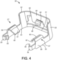
- FIGS. 1 and 4 illustrate an example bracket 50 of the present disclosure.
- the bracket 50 is arranged to capture endform 14 when the endform 14 is installed in the socket portion 27 of the receptacle body 20.
- the bracket 50 is comprised of a rear bulkhead 58 extending into a pair of curved walls 52. Each wall 52 is located on an opposite side of the bulkhead 58.
- a pair of legs 53 project outward from a portion of each curved wall 52.
- the pair of legs 53 includes one leg 53 projecting from a portion of a first curved wall 52 and another leg 53 projecting from a second curved wall 52 on an opposite end of bulkhead 58 such that the pair of legs 53 are laterally spaced apart.
- Each leg 53 terminates at a hook-shaped finger 54.
- Each finger 54 includes an inwardly facing flange member 55.
- Each leg 53 further includes a spring latch 57 extending from each leg.
- Each spring latch 57 has a first member 59 extending perpendicularly from a respective leg 53 and second member 60 folded over and oriented at an acute angle from the first member 59.
- the second member 60 of each spring latch 57 is arranged to allow deflection of the second member 60 toward the first member 59 when a force is applied to a top surface 61 and to resist bending of the second member 60 when a force is applied to a bottom surface 62.
- the bracket 50 further includes a lower wall section 51 extending along the back of the bracket 50 in alignment with the bulkhead 58 between the pair of curved walls 52.
- An opening 66 extends into a pair of recesses 65.
- the opening 66 is formed between the bulkhead 58 and the wall section 51.
- Each recess 65 is adapted to receive therethrough a respective arm 82 of the verifier 80 when the verifier ins installed to the bracket 50.
- a clasping hook 68 extends inward from bulkhead 58 and is arranged to engage a locking notch 88 on the verifier 80.
- the bracket 50 is preferably formed as a unitary structure from a metal material, such as for example, a spring steel. However, it could also be formed from other resilient materials, such as for example, molded from a thermoplastic that would allow the proper deflection of the second member 60 of spring latches 57.
- the bracket 50 is arranged to be installed to an upper section 44 of socket portion 27 after installation of sealing member 30 within the sealing section 28.
- the upper section 44 is generally "D" shaped and includes a peripheral wall 70 extending about the socket opening 74.
- Wall 70 includes a pair of curved wall sections 72 extending from a bulkhead wall section 78. Curved wall sections 72 and bulkhead wall section 78 have external faces that conform to the internal faces of curved walls 52 and bulkhead 58 respectively, of the bracket 50.
- Wall 70 includes a pair of wall sections 73 located opposite of the other on either side of the socket opening 74.
- a pair of latch openings 71 are formed through wall 70 adjacent wall sections 73.
- a pair of flange member openings 77 extend through wall 70 each located on an opposite end of the wall 70. Each flange member opening 77 is arranged to accept therein a respective flange member 55 of each leg 53 of bracket 50.
- a pair of verifier recesses 75 extend from each side of a central opening 76 which extend through wall 70 below bulkhead section 58. The pair of verifier recesses 75 and central opening 76 have a general shape and dimension as to conform to recesses 65 and opening 66 respectively of the bracket 50. In combination, recesses 65 and 75 and openings 66 and 76 provide a passthrough to accept the installation of verifier 80 through the bracket 50 and the upper section 44 wall 70 of the socket portion 27.
- FIG. 6 illustrates the bracket 50 installed in the upper section 44 of the socket portion 27 in an endform accepting position.
- a respective second member 60 extends through a respective opening 71 into the socket opening 74.
- the bracket 50 is held in the installation ready condition by the grasping a flange members 55 in flange member openings 77.
- the verifier 80 includes a crossmember 81 having a pair of arms 82 which project from opposite ends of the crossmember 81.
- the pair of arms includes one arm 82 projecting from one end of the crossmember 81 and another arm 82 projecting from the opposite end of the crossmember 81 such that the arms 82 are laterally spaced apart and are identical to the other.
- Each arm 82 includes a stop member 83 extending perpendicularly from a top surface of each arm and a billboard member 84 located adjacent to each stop member 83.
- Each billboard member 84 includes a generally planar surface 85 arranged to have verifying indicia, for example a QR code or other distinguishing marks printed or applied on surface 85 to provide a visual or machine readable verification of the proper installation of the endform 14.
- the verifier 80 crossmember 81 further includes a push surface 86 extending perpendicularly from the crossmember 81 and a set of fixing fingers 87 extending perpendicularly from a top surface of the crossmember 81.
- the fixing fingers 87 extend from crossmember 81 generally parallel to arms 82.
- a locking notch 88 is formed on a center finger of the locking fingers 87 adjacent the push surface 86.
- Each arm 82 includes a chamfered surface 89 formed on the inner face of each arm 82 that slope radially upward from the inner face of each arm 82.
- the inner edges of the arms 82 are spaced apart a distance smaller than the outer diameter of the upset 18 formed about endform 14.
- the outer edges of each arm 82 are generally linear or straight in orientation and arranged to fit within the recesses 65 of the bracket 50 and the recesses 75 of the socket portion 27 upper portion 44.
- the verifier 80 is formed of a resilient material, preferably molded from a thermoplastic, such that each arm 82 may flex and deflect radially outwardly as the verifier 80 is installed. That is, the chamfered surfaces 89 of each arm 82 travel against an installed upset 18 and arranged to urge each arms 82 laterally outward as arms 82 travel across the upset 18 which will be explained in more detail below.
- FIG. 6 illustrates an example embodiment of the present disclosure wherein the quick connector assembly 10 is in an installation ready condition, such as for example, when the quick connector assembly 10 is manufactured and ready to accept within the socket opening 74 an endform 14.
- the sealing member 30 is installed in sealing section 28, and the bracket 50 and the verifier 80 are installed to the socket portion 27.
- the bracket 50 is installed on the wall 70 of socket portion 27 upper section 44 with a respective second member 60 of the spring latches 57 extending through a respective opening 71.
- Each second member 60 of each spring latch 57 extends into the socket cavity 74.
- the bracket 50 is retained in the installation ready condition by the action of a respective flange member 55 grasping a respective flange member opening 77.
- the verifier 80 has each arm 82 inserted into the socket cavity 74 through a respective recess 65 of the bracket 50. Fixing fingers 87 are partially inserted through opening 66. Opening 66 and recesses 65 are located above wall 51 on the bracket 50 and thereby positions the verifier arms 82 and fixing fingers 87 above the surface 33 of the sealing member 30.
- the verifier 80 is prevented from being fully inserted into the socket cavity 74 by a front surface of each stop member 83 engaging an edge of bulkhead 58. Additional movement of the verifier 80 into socket cavity 74 would require the each stop member 83 be disengaged from the edge of bulkhead 58 to allow the stop members 83 to enter the socket cavity 74 through their respective recesses 65. This can only be accomplished when the endform 14 is installed in the socket cavity 74.
- the insertion portion 15 of the endform 14 is aligned with and inserted into receiver opening 39 of the sealing member 30.
- the upset 18 enters the socket cavity 74 and contacts the top surface 61 of each second member 60 of the spring latches 57.
- a continued applied force in axial direction A will cause deflection of each second member 60 inwardly toward the first member 59 by the upset 18 pushing each second member 60 away from the upset 18.
- each of the second members 60 returns to its relaxed position capturing the upset 18 between the sealing member surface 33 and a bottom surface 62 of each spring latch second member 60, as is best seen in FIG. 8 .
- the endform 14 is now in an installed condition and retained within socket portion 27.
- the insertion portion 15 of endform 14 is installed within receiver opening 39 of the sealing member 30 making a fluid tight seal between the endform 14 and the sealing member 30 by elastically deforming the O-rings 43 against the insertion portion 15 that extend into receiver opening 39 from the channel 41 openings.
- each arm 82 aligns with an outer edge of upset 18.
- Applying a force to push surface 86 in direction B will cause each arm of the verifier 80 to travel along the exterior surface of the upset 18.
- Each arm 82 will be deflected outwardly toward the wall 70 as it travels along the upset 18 exterior surface. The outward deflection will disengage each stop member 83 from the edge of the bulkhead 58 allowing each stop member 83 to enter the socket cavity 74 via a respective recess 65 and 75.
- the placement of the fixing fingers 87 over the upset 18 enhances the hold of the upset 18, assuring that the endform 14 is held firmly in the socket portion 27.
- the verifier 80 With the capture of the clasping hook 68 by the notch 88, the verifier 80 now becomes locked to bracket 50. Any subsequent movement of the bracket 50, such as for example, movement of the bracket 50 to unlatch the endform 14 from the receptacle body 20 will now also move the verifier 80.
- each billboard member 84 surface 85 becomes visible through a respective opening 71 of the socket portion 27.
- a QR code applied on each surface 85 becomes visible through a respective opening 71.
- the QR code can be read by a hand held visual scanner allowing for machine scanning and recording of the positive engagement of the endform 14 to the receptacle body 20. It will be appreciated by those skilled in the art that other forms of code or indicia may be printed on surface 85 to provide a visible indication of a positive engagement of the endform 14 to the receptacle body 20.
- the endform 14 can be removed from the receptacle body 20 for servicing or replacement.
- each flange member 55 on each bracket arm 53 is manually removed from a respective flange member opening 77 and the bracket 50 moved backward in direction C as shown in FIG. 11 , thereby placing the quick connector assembly 10 into a serviceable condition.
- the bulkhead 58 and the curved walls 52 of bracket 50 are pulled back from the socket portion 27 curved wall sections 72 until each flange member 55 enters into a respective retainer notch 79 and arresting any further backward movement of the bracket 50.
- each second member 60 of each spring latch 57 is moved to a position where each member 60 is not located over upset 18. Since the verifier 80 now moves along with the bracket 50, the backward movement of the bracket 50 also moves fixing fingers 87 into a position where the fixing fingers 87 are not located over upset 18.
- the endform 14 can now be removed from the receptacle body 20 by pulling the endform 14 from socket portion 27 in direction D.
- the endform 14 can be reinstalled into socket portion 27 and the bracket 50 repositioned to capture the endform 14.
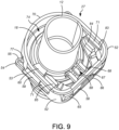
- Reapplying a force to push surface 86 in direction B disengages flange members 55 from retainer notches 79 moving the bracket 50 back into the installed condition and engage flange members 55 to respective flange member openings 77 of the installed condition as shown in FIG. 9 .
- verifier 80 also now moves in concert with the bracket 50 movement of the bracket 80 into the installed condition will also move the verifier 80 into the verification condition as shown in FIG. 10 .
- the quick connector assembly described herein provides the benefits of only requiring access from one side, for example, top, bottom, left or right in order to operate the components of the connector (e.g., retainer and verifier) and to connect the fluid tubes together.
- the quick connector assembly of the present disclosure can be coupled to male and female components in any radial direction, the quick connector assembly can be oriented to provide the most convenient access for an installer or user. In this way, packaging of the quick connector assembly is improved, and routing of fluid lines is made more robust and variable in a variety of different environments.
- the quick connector assembly has numerous applications where a fluid-tight, but serviceable connection is desired. Within the industry a serviceable connection is a connection were the fluid carrying components of a quick connector can be disconnected from each other for the purposes of maintenance or the servicing of components of the quick connector assembly.
Landscapes
- Engineering & Computer Science (AREA)
- General Engineering & Computer Science (AREA)
- Mechanical Engineering (AREA)
- Quick-Acting Or Multi-Walled Pipe Joints (AREA)
Claims (11)
- Schnellverbinderanordnung (10), umfassend:einen Aufnahmekörper (20) mit einem Hohlraum (29), der sich durch den Aufnahmekörper (20) zu einem Schaftteil (25) erstreckt, der mit einem zweiten Fluidrohr verbunden ist;einen Dichtungsabschnitt (28), der sich innerhalb des Hohlraums (29) befindet;einen Buchsenteil (27) mit einer Wand (70), die sich vom Dichtungsabschnitt erstreckt und eine Buchsenöffnung (74) in Ausrichtung mit dem Hohlraum (29) begrenzt, und mit einem Paar Ausnehmungen (75), die sich durch die Buchsenteilwand erstrecken, und einem Paar Verriegelungsöffnungen (71), die sich durch einen Teil der Wand (70) in die Buchsenöffnung erstrecken;einen Prüfer (80) mit einem Paar Armen (82), die sich von beiden Seiten einer Druckfläche (86) erstrecken, wobei jeder Prüferarm (82) durch eine betreffende Ausnehmung (75) in die Buchsenöffnung installiert ist;ein Dichtungselement (30) mit einer Aufnahmeöffnung (39), das im Dichtungsabschnitt (28) installiert ist, wobei die Aufnahmeöffnung mit der Buchsenöffnung und dem Schaftteil ausgerichtet ist;eine Halterung (50), die an der Wand (70) angebracht ist und ein Paar Federverriegelungen (57) umfasst, wobei sich jede Federverriegelung durch eine betreffende der Verriegelungsöffnungen (71) in die Buchsenöffnung erstreckt;ein erstes Fluidrohr (12) mit einem Einführungsabschnitt (15) und einer erhöhten Verdickung (18), wobei der Einführungsabschnitt durch die Buchsenöffnung in die Aufnahmeöffnung (39) platziert wird, eine Fluidverbindung zum zweiten Fluidrohr herstellt und bewirkt, dass der Wulst (18) durch jede Federverriegelung (57) erfasst wird, wodurch das erste Fluidrohr am Aufnahmekörper gehalten wird, dadurch gekennzeichnet, dass der Prüfer (80) Fixierfinger (87) umfasst, die sich von der Prüferdruckfläche (86) zwischen dem Paar Prüferarme (82) erstrecken, wobei die Fixierfinger (87) den Wulst (18) des ersten Fluidrohrs erfassen, wenn sich jeder Prüferarm (82) vollständig in den Buchsenhohlraum auf beiden Seiten des Wulstes (18) erstreckt; undjeder Prüferarm (82) ferner ein Anzeigeelement (84) mit Prüfsymbolen umfasst, die sich auf einer Anzeigefläche (85) befinden, wobei jede Anzeigefläche (85) durch eine betreffende Verriegelungsöffnung (71) sichtbar ist, wenn sich jeder Prüferarm (82) vollständig in den Buchsenhohlraum erstreckt, wodurch die Kopplung des ersten Fluidrohrs mit dem Aufnahmekörper geprüft wird.
- Schnellverbinderanordnung nach Anspruch 1, wobei die Anordnung ferner umfasst:
ein Anschlagelement (83), das sich von jedem Prüferarm (82) erstreckt, wobei jedes Anschlagelement mit der Halterung (50) in Eingriff steht und verhindert, dass sich jeder Prüferarm (82) vollständig in die Buchsenöffnung (74) erstreckt. - Schnellverbinderanordnung nach Anspruch 2, wobei nach dem Erfassen des Wulstes (18) des ersten Fluidrohrs durch jede der Federverriegelungen (57) eine auf die Prüferdruckfläche (86) ausgeübte Kraft bewirkt, dass sich jeder Prüferarm (82) entlang des Wulstes (18) des ersten Fluidrohrs bewegt, wodurch jedes Anschlagelement (83) von der Halterung (50) gelöst wird und jeder Prüferarm (82) sich vollständig in den Buchsenhohlraum auf beiden Seiten des Wulstes (18) und unterhalb einer betreffenden Federverriegelung (57) erstrecken kann.
- Schnellverbinderanordnung nach Anspruch 1, wobei die Prüfsymbole ein maschinenlesbarer Code sind, der durch eine Abtastvorrichtung abtastbar ist.
- Schnellverbinderanordnung nach Anspruch 4, wobei die Halterung (50) ferner ein Paar Flanschelemente (55) umfasst, die mit einem Paar Flanschelementöffnungen (77) in Eingriff stehen, die sich durch die Buchsenteilwand (70) erstrecken, wenn die Halterung (50) am Buchsenteil (27) installiert ist.
- Schnellverbinderanordnung nach Anspruch 5, wobei jede Verriegelungsöffnung (71) ferner eine Halteelementkerbe (79) umfasst und wobei die Flanschelemente (55) der Halterung aus den Flanschelementöffnungen (77) gelöst werden, sodass sich die Halterung (50) und der Prüfer (80) bewegen können, was bewirkt, dass jede Federverriegelung (57) und die Fixierfinger (87) vom Wulst (18) des ersten Fluidrohrs weggleiten, bis jedes Flanschelement (55) in eine betreffende Halteelementkerbe (79) eintritt und dabei jede Federverriegelung (57) in eine Position bringt, die das Entfernen des ersten Fluidrohrs aus dem Aufnahmekörper ermöglicht.
- Verfahren zum Bilden einer Kupplung in einer Fluidleitung zwischen einem ersten und einem zweiten Fluidrohr, wobei das Verfahren umfasst:Koppeln des zweiten Fluidrohrs mit einem Schaft (25) eines Aufnahmekörpers (20), der einen sich durch den Aufnahmekörper (20) erstreckenden Hohlraum (29) aufweist;Bilden eines Dichtungsabschnitts (28) innerhalb des Hohlraums (29) und Installieren eines Dichtungselements (30) mit einer Aufnahmeöffnung (39) im Dichtungsabschnitt (28), wobei die Aufnahmeöffnung (39) mit einer Buchsenöffnung (74) und dem Schaft (25) ausgerichtet ist;Bilden eines sich vom Dichtungsabschnitt (28) erstreckenden Buchsenteils (27) mit einer Wand (70), die die mit der Aufnahmeöffnung (39) ausgerichtete Buchsenöffnung (74) begrenzt, einschließlich des Bildens eines Paars Ausnehmungen (75), die sich durch die Buchsenteilwand (70) erstrecken, und eines Paars Verriegelungsöffnungen (71), die sich durch einen Teil der Wand (70) in die Buchsenöffnung erstrecken;Bereitstellen eines Prüfers (80) mit einem Paar Arme (82), die sich von beiden Seiten einer Druckfläche (86) erstrecken;Installieren einer Halterung (50) an der Wand (70), einschließlich eines Paars Federverriegelungen (57), wobei sich jede Federverriegelung durch eine betreffende des Paars Verriegelungsöffnungen (71) in die Buchsenöffnung (74) erstreckt;Bilden einer Endform (14) am ersten Fluidrohr (12), einschließlich eines Einführungsabschnitts (15) und eines erhöhten Wulstes (18);Bringen des Prüfers (80) in einen installationsbereiten Zustand durch Installieren eines Prüferarms (82) durch eine betreffende Ausnehmung (75) in die Buchsenöffnung (74), bis ein sich von jedem Arm (82) erstreckendes Anschlagelement (83) mit der Halterung (50) in Eingriff steht und verhindert, dass sich jeder Arm vollständig in die Buchsenöffnung (74) erstreckt; undEinführen des Einführungsabschnitts (15) durch die Buchsenöffnung (74) in die Aufnahmeöffnung (39), wodurch eine Fluidkopplung zum zweiten Fluidrohr hergestellt wird und der Wulst (18) durch jede Federverriegelung (57) erfasst und das erste Fluidrohr am Aufnahmekörper gehalten wird, dadurch gekennzeichnet, dass der Prüfer (80) ferner Fixierfinger (87) umfasst, die sich von der Prüferdruckfläche (86) zwischen dem Paar Prüferarme erstrecken, und jeder Prüferarm (82) eine Anzeigefläche (85) mit Prüfsymbolen auf der Anzeigefläche umfasst,wobei der Wulst (18) des ersten Fluidrohrs durch die Fixierfinger (87) erfasst wird, wenn der Prüfer in einen installierten Zustand gebracht wird, indem eine Kraft auf die Prüferdruckfläche (86) ausgeübt wird, wodurch sich jeder Prüferarm entlang des Wulstes (18) des ersten Fluidrohrs bewegt, was bewirkt, dass jede Anzeigefläche durch eine betreffende Verriegelungsöffnung (71) sichtbar wird und die Kopplung des ersten Fluidrohrs mit dem Aufnahmekörper geprüft wird.
- Verfahren nach Anspruch 7, wobei im installierten Zustand jedes Anschlagelement (83) von der Halterung (50) gelöst ist, wodurch sich jeder Prüferarm (82) vollständig in den Buchsenhohlraum auf beiden Seiten des Wulstes (18) und unterhalb einer betreffenden Federverriegelung (57) erstrecken kann.
- Verfahren nach Anspruch 7, wobei die Prüfsymbole ein maschinenlesbarer Code sind, der durch eine Abtastvorrichtung abtastbar ist.
- Verfahren nach Anspruch 9, wobei die Halterung (50) ferner ein Paar Flanschelemente (55) umfasst und das Buchsenteil (27) ferner ein Paar Flanschelementöffnungen (77) umfasst, die sich durch die Buchsenteilwand (70) erstrecken, wobei das Verfahren ferner umfasst:
Greifen einer Flanschelementöffnung (77) durch ein betreffendes Flanschelement (55), wenn die Halterung am Buchsenteil installiert wird. - Verfahren nach Anspruch 10, wobei jede Verriegelungsöffnung (71) ferner eine Halteelementkerbe (79) umfasst, wobei das Verfahren ferner ein Verfahren zum Lösen der Kopplung in der Fluidleitung zwischen dem ersten und dem zweiten Fluidrohr umfasst durch:Lösen der Flanschelemente (55) der Halterung aus den Flanschelementöffnungen (77);Bewegen der Halterung (50) und des Prüfers (80), wodurch jede Federverriegelung (57) und die Fixierfinger (87) vom Wulst (18) des ersten Fluidrohrs weggleiten, bis jedes Flanschelement (55) in eine betreffende Halteelementkerbe (79) eintritt; undEntfernen des ersten Fluidrohrs aus dem Aufnahmekörper.
Priority Applications (1)
| Application Number | Priority Date | Filing Date | Title |
|---|---|---|---|
| EP24205277.7A EP4467861A3 (de) | 2021-08-18 | 2022-08-17 | Schnellkupplung mit prüfer |
Applications Claiming Priority (1)
| Application Number | Priority Date | Filing Date | Title |
|---|---|---|---|
| US202163234243P | 2021-08-18 | 2021-08-18 |
Related Child Applications (1)
| Application Number | Title | Priority Date | Filing Date |
|---|---|---|---|
| EP24205277.7A Division EP4467861A3 (de) | 2021-08-18 | 2022-08-17 | Schnellkupplung mit prüfer |
Publications (2)
| Publication Number | Publication Date |
|---|---|
| EP4137732A1 EP4137732A1 (de) | 2023-02-22 |
| EP4137732B1 true EP4137732B1 (de) | 2024-10-09 |
Family
ID=82942316
Family Applications (2)
| Application Number | Title | Priority Date | Filing Date |
|---|---|---|---|
| EP22190762.9A Active EP4137732B1 (de) | 2021-08-18 | 2022-08-17 | Schnellverbinder mit prüfer |
| EP24205277.7A Pending EP4467861A3 (de) | 2021-08-18 | 2022-08-17 | Schnellkupplung mit prüfer |
Family Applications After (1)
| Application Number | Title | Priority Date | Filing Date |
|---|---|---|---|
| EP24205277.7A Pending EP4467861A3 (de) | 2021-08-18 | 2022-08-17 | Schnellkupplung mit prüfer |
Country Status (3)
| Country | Link |
|---|---|
| US (1) | US12281738B2 (de) |
| EP (2) | EP4137732B1 (de) |
| CN (1) | CN115707895A (de) |
Families Citing this family (4)
| Publication number | Priority date | Publication date | Assignee | Title |
|---|---|---|---|---|
| CN114593297B (zh) * | 2022-03-24 | 2024-06-18 | 瑞肯耐特流体控制系统(镇江)有限公司 | 快速连接器 |
| US12104729B2 (en) | 2022-08-30 | 2024-10-01 | A. Raymond Et Cie | Quick connector verification system and related method of use |
| DE102022126011A1 (de) * | 2022-10-07 | 2024-04-18 | Norma Germany Gmbh | Verbindungssystem zum Leiten von Fluid |
| FR3166190A1 (fr) * | 2024-09-10 | 2026-03-13 | A. Raymond Et Cie | Connecteur rapide |
Family Cites Families (16)
| Publication number | Priority date | Publication date | Assignee | Title |
|---|---|---|---|---|
| US7390025B2 (en) * | 2004-03-31 | 2008-06-24 | Ti Group Automotive Systems, Llc | Secondary latch/verifier for a quick connector |
| US7484774B2 (en) | 2005-05-03 | 2009-02-03 | Ti Group Automotive Systems, Llc | Redundant latch/verifier for a quick connector |
| US9016729B2 (en) | 2005-12-06 | 2015-04-28 | Sumitomo Riko Company Limited | Quick connector and checker |
| US8240716B2 (en) * | 2008-08-07 | 2012-08-14 | TI Group Automotive System, LLC | Quick connector coupling with pull tab verifier |
| US20100052315A1 (en) * | 2008-08-28 | 2010-03-04 | Ti Group Automotive Systems, Llc | Quick connector coupling with lateral stabilization |
| JP4554700B2 (ja) | 2008-09-26 | 2010-09-29 | 三桜工業株式会社 | クイックコネクタ |
| FR2945100A1 (fr) * | 2009-04-30 | 2010-11-05 | Hutchinson | Raccord encliquetable entre un conduit de fluide et un embout rigide avec un dispositif temoin de connexion et procede de controle de cette connexion |
| JP5497223B1 (ja) | 2013-04-16 | 2014-05-21 | 三桜工業株式会社 | 配管継手 |
| US10422459B2 (en) * | 2015-01-14 | 2019-09-24 | Norma U.S. Holding Llc | Conduit connector with a primary and secondary latch |
| US10550982B2 (en) | 2016-06-17 | 2020-02-04 | Ti Group Automotive Systems, Llc | Quick connector |
| US10816121B2 (en) | 2017-05-09 | 2020-10-27 | Martinrea International US Inc. | Quick connect coupling with verifier |
| US11199281B2 (en) | 2018-01-31 | 2021-12-14 | A. Raymond Et Cie. | Dual-latch quick connector |
| KR200497939Y1 (ko) | 2019-02-11 | 2024-04-18 | 한일튜브 주식회사 | 검증기 기구를 갖는 퀵 커넥터 |
| DE202020103903U1 (de) | 2020-07-06 | 2020-07-13 | TI Automotive (Fuldabrück) GmbH | Verbinder zum Verbinden zweier fluidführender Elemente |
| US11365840B2 (en) * | 2020-11-20 | 2022-06-21 | A. Raymond Et Cie | Code verification sleeve for a quick connector |
| EP4232736B1 (de) * | 2021-02-12 | 2025-06-11 | A. Raymond et Cie | Schnellkupplung mit prüfung und prüfung der montage |
-
2022
- 2022-07-18 US US17/867,374 patent/US12281738B2/en active Active
- 2022-08-08 CN CN202210942200.3A patent/CN115707895A/zh active Pending
- 2022-08-17 EP EP22190762.9A patent/EP4137732B1/de active Active
- 2022-08-17 EP EP24205277.7A patent/EP4467861A3/de active Pending
Also Published As
| Publication number | Publication date |
|---|---|
| US20230055432A1 (en) | 2023-02-23 |
| EP4137732A1 (de) | 2023-02-22 |
| CN115707895A (zh) | 2023-02-21 |
| US12281738B2 (en) | 2025-04-22 |
| EP4467861A2 (de) | 2024-11-27 |
| EP4467861A3 (de) | 2025-03-05 |
Similar Documents
| Publication | Publication Date | Title |
|---|---|---|
| EP4137732B1 (de) | Schnellverbinder mit prüfer | |
| CA2169153C (en) | Quick connector with integral release mechanism | |
| EP3467367B1 (de) | Manipulationssichere permanente schnellkupplungsvorrichtung | |
| US5568946A (en) | Squeeze-to-release quick connector with snap-in retainer | |
| CN111379915B (zh) | 快速连接器 | |
| RU2413121C2 (ru) | Быстродействующее соединительное устройство и средство контроля | |
| EP3943795B1 (de) | Schnellverbinderverriegelungsprüfung unter verwendung eines mehrteiligen abtastbaren codes | |
| EP1909016B1 (de) | Schnellverbindungskupplung | |
| EP0946841B1 (de) | Durch drücken lösbare schnellkupplung | |
| EP1582800B1 (de) | Sekundäres Verriegelungs- bzw. Kontrollelement für eine Schnellkupplung | |
| EP0505930B1 (de) | Anzeige-Einsteck-Clip für Schnellverbindungen | |
| US5009454A (en) | Swivelable quick connector assembly | |
| EP4400755B1 (de) | Verbinder mit geführtem pilot | |
| EP4148313B1 (de) | Schnelltrennverbinder mit trockentrennung | |
| JPH08509281A (ja) | クイックコネクタ | |
| EP4372262A1 (de) | Steckverbinder mit führungselementen | |
| EP1719944B2 (de) | Schnellkupplung | |
| CN100458258C (zh) | 具有释放机构的连接器 | |
| US12146596B2 (en) | Quick connector with removable verifier | |
| KR200497939Y1 (ko) | 검증기 기구를 갖는 퀵 커넥터 | |
| US11982382B2 (en) | Quick connector with bracket retainer |
Legal Events
| Date | Code | Title | Description |
|---|---|---|---|
| PUAI | Public reference made under article 153(3) epc to a published international application that has entered the european phase |
Free format text: ORIGINAL CODE: 0009012 |
|
| STAA | Information on the status of an ep patent application or granted ep patent |
Free format text: STATUS: THE APPLICATION HAS BEEN PUBLISHED |
|
| AK | Designated contracting states |
Kind code of ref document: A1 Designated state(s): AL AT BE BG CH CY CZ DE DK EE ES FI FR GB GR HR HU IE IS IT LI LT LU LV MC MK MT NL NO PL PT RO RS SE SI SK SM TR |
|
| STAA | Information on the status of an ep patent application or granted ep patent |
Free format text: STATUS: REQUEST FOR EXAMINATION WAS MADE |
|
| 17P | Request for examination filed |
Effective date: 20230822 |
|
| RBV | Designated contracting states (corrected) |
Designated state(s): AL AT BE BG CH CY CZ DE DK EE ES FI FR GB GR HR HU IE IS IT LI LT LU LV MC MK MT NL NO PL PT RO RS SE SI SK SM TR |
|
| GRAP | Despatch of communication of intention to grant a patent |
Free format text: ORIGINAL CODE: EPIDOSNIGR1 |
|
| STAA | Information on the status of an ep patent application or granted ep patent |
Free format text: STATUS: GRANT OF PATENT IS INTENDED |
|
| INTG | Intention to grant announced |
Effective date: 20240715 |
|
| GRAS | Grant fee paid |
Free format text: ORIGINAL CODE: EPIDOSNIGR3 |
|
| GRAA | (expected) grant |
Free format text: ORIGINAL CODE: 0009210 |
|
| STAA | Information on the status of an ep patent application or granted ep patent |
Free format text: STATUS: THE PATENT HAS BEEN GRANTED |
|
| P01 | Opt-out of the competence of the unified patent court (upc) registered |
Free format text: CASE NUMBER: APP_45378/2024 Effective date: 20240806 |
|
| RAP3 | Party data changed (applicant data changed or rights of an application transferred) |
Owner name: COOPER-STANDARD AUTOMOTIVE INC. |
|
| AK | Designated contracting states |
Kind code of ref document: B1 Designated state(s): AL AT BE BG CH CY CZ DE DK EE ES FI FR GB GR HR HU IE IS IT LI LT LU LV MC MK MT NL NO PL PT RO RS SE SI SK SM TR |
|
| REG | Reference to a national code |
Ref country code: CH Ref legal event code: EP |
|
| REG | Reference to a national code |
Ref country code: DE Ref legal event code: R096 Ref document number: 602022006646 Country of ref document: DE |
|
| REG | Reference to a national code |
Ref country code: IE Ref legal event code: FG4D |
|
| REG | Reference to a national code |
Ref country code: LT Ref legal event code: MG9D |
|
| REG | Reference to a national code |
Ref country code: NL Ref legal event code: MP Effective date: 20241009 |
|
| REG | Reference to a national code |
Ref country code: AT Ref legal event code: MK05 Ref document number: 1730931 Country of ref document: AT Kind code of ref document: T Effective date: 20241009 |
|
| PG25 | Lapsed in a contracting state [announced via postgrant information from national office to epo] |
Ref country code: NL Free format text: LAPSE BECAUSE OF FAILURE TO SUBMIT A TRANSLATION OF THE DESCRIPTION OR TO PAY THE FEE WITHIN THE PRESCRIBED TIME-LIMIT Effective date: 20241009 |
|
| PG25 | Lapsed in a contracting state [announced via postgrant information from national office to epo] |
Ref country code: NL Free format text: LAPSE BECAUSE OF FAILURE TO SUBMIT A TRANSLATION OF THE DESCRIPTION OR TO PAY THE FEE WITHIN THE PRESCRIBED TIME-LIMIT Effective date: 20241009 |
|
| PG25 | Lapsed in a contracting state [announced via postgrant information from national office to epo] |
Ref country code: HR Free format text: LAPSE BECAUSE OF FAILURE TO SUBMIT A TRANSLATION OF THE DESCRIPTION OR TO PAY THE FEE WITHIN THE PRESCRIBED TIME-LIMIT Effective date: 20241009 Ref country code: IS Free format text: LAPSE BECAUSE OF FAILURE TO SUBMIT A TRANSLATION OF THE DESCRIPTION OR TO PAY THE FEE WITHIN THE PRESCRIBED TIME-LIMIT Effective date: 20250209 Ref country code: PT Free format text: LAPSE BECAUSE OF FAILURE TO SUBMIT A TRANSLATION OF THE DESCRIPTION OR TO PAY THE FEE WITHIN THE PRESCRIBED TIME-LIMIT Effective date: 20250210 |
|
| PG25 | Lapsed in a contracting state [announced via postgrant information from national office to epo] |
Ref country code: FI Free format text: LAPSE BECAUSE OF FAILURE TO SUBMIT A TRANSLATION OF THE DESCRIPTION OR TO PAY THE FEE WITHIN THE PRESCRIBED TIME-LIMIT Effective date: 20241009 |
|
| PG25 | Lapsed in a contracting state [announced via postgrant information from national office to epo] |
Ref country code: BG Free format text: LAPSE BECAUSE OF FAILURE TO SUBMIT A TRANSLATION OF THE DESCRIPTION OR TO PAY THE FEE WITHIN THE PRESCRIBED TIME-LIMIT Effective date: 20241009 |
|
| PG25 | Lapsed in a contracting state [announced via postgrant information from national office to epo] |
Ref country code: ES Free format text: LAPSE BECAUSE OF FAILURE TO SUBMIT A TRANSLATION OF THE DESCRIPTION OR TO PAY THE FEE WITHIN THE PRESCRIBED TIME-LIMIT Effective date: 20241009 |
|
| PG25 | Lapsed in a contracting state [announced via postgrant information from national office to epo] |
Ref country code: NO Free format text: LAPSE BECAUSE OF FAILURE TO SUBMIT A TRANSLATION OF THE DESCRIPTION OR TO PAY THE FEE WITHIN THE PRESCRIBED TIME-LIMIT Effective date: 20250109 |
|
| PG25 | Lapsed in a contracting state [announced via postgrant information from national office to epo] |
Ref country code: LV Free format text: LAPSE BECAUSE OF FAILURE TO SUBMIT A TRANSLATION OF THE DESCRIPTION OR TO PAY THE FEE WITHIN THE PRESCRIBED TIME-LIMIT Effective date: 20241009 Ref country code: GR Free format text: LAPSE BECAUSE OF FAILURE TO SUBMIT A TRANSLATION OF THE DESCRIPTION OR TO PAY THE FEE WITHIN THE PRESCRIBED TIME-LIMIT Effective date: 20250110 Ref country code: AT Free format text: LAPSE BECAUSE OF FAILURE TO SUBMIT A TRANSLATION OF THE DESCRIPTION OR TO PAY THE FEE WITHIN THE PRESCRIBED TIME-LIMIT Effective date: 20241009 |
|
| PG25 | Lapsed in a contracting state [announced via postgrant information from national office to epo] |
Ref country code: PL Free format text: LAPSE BECAUSE OF FAILURE TO SUBMIT A TRANSLATION OF THE DESCRIPTION OR TO PAY THE FEE WITHIN THE PRESCRIBED TIME-LIMIT Effective date: 20241009 |
|
| PG25 | Lapsed in a contracting state [announced via postgrant information from national office to epo] |
Ref country code: RS Free format text: LAPSE BECAUSE OF FAILURE TO SUBMIT A TRANSLATION OF THE DESCRIPTION OR TO PAY THE FEE WITHIN THE PRESCRIBED TIME-LIMIT Effective date: 20250109 |
|
| PG25 | Lapsed in a contracting state [announced via postgrant information from national office to epo] |
Ref country code: SM Free format text: LAPSE BECAUSE OF FAILURE TO SUBMIT A TRANSLATION OF THE DESCRIPTION OR TO PAY THE FEE WITHIN THE PRESCRIBED TIME-LIMIT Effective date: 20241009 |
|
| PG25 | Lapsed in a contracting state [announced via postgrant information from national office to epo] |
Ref country code: DK Free format text: LAPSE BECAUSE OF FAILURE TO SUBMIT A TRANSLATION OF THE DESCRIPTION OR TO PAY THE FEE WITHIN THE PRESCRIBED TIME-LIMIT Effective date: 20241009 |
|
| REG | Reference to a national code |
Ref country code: DE Ref legal event code: R097 Ref document number: 602022006646 Country of ref document: DE |
|
| PG25 | Lapsed in a contracting state [announced via postgrant information from national office to epo] |
Ref country code: EE Free format text: LAPSE BECAUSE OF FAILURE TO SUBMIT A TRANSLATION OF THE DESCRIPTION OR TO PAY THE FEE WITHIN THE PRESCRIBED TIME-LIMIT Effective date: 20241009 |
|
| PG25 | Lapsed in a contracting state [announced via postgrant information from national office to epo] |
Ref country code: RO Free format text: LAPSE BECAUSE OF FAILURE TO SUBMIT A TRANSLATION OF THE DESCRIPTION OR TO PAY THE FEE WITHIN THE PRESCRIBED TIME-LIMIT Effective date: 20241009 |
|
| PG25 | Lapsed in a contracting state [announced via postgrant information from national office to epo] |
Ref country code: SK Free format text: LAPSE BECAUSE OF FAILURE TO SUBMIT A TRANSLATION OF THE DESCRIPTION OR TO PAY THE FEE WITHIN THE PRESCRIBED TIME-LIMIT Effective date: 20241009 |
|
| PG25 | Lapsed in a contracting state [announced via postgrant information from national office to epo] |
Ref country code: CZ Free format text: LAPSE BECAUSE OF FAILURE TO SUBMIT A TRANSLATION OF THE DESCRIPTION OR TO PAY THE FEE WITHIN THE PRESCRIBED TIME-LIMIT Effective date: 20241009 |
|
| PG25 | Lapsed in a contracting state [announced via postgrant information from national office to epo] |
Ref country code: IT Free format text: LAPSE BECAUSE OF FAILURE TO SUBMIT A TRANSLATION OF THE DESCRIPTION OR TO PAY THE FEE WITHIN THE PRESCRIBED TIME-LIMIT Effective date: 20241009 |
|
| PLBE | No opposition filed within time limit |
Free format text: ORIGINAL CODE: 0009261 |
|
| STAA | Information on the status of an ep patent application or granted ep patent |
Free format text: STATUS: NO OPPOSITION FILED WITHIN TIME LIMIT |
|
| PG25 | Lapsed in a contracting state [announced via postgrant information from national office to epo] |
Ref country code: SE Free format text: LAPSE BECAUSE OF FAILURE TO SUBMIT A TRANSLATION OF THE DESCRIPTION OR TO PAY THE FEE WITHIN THE PRESCRIBED TIME-LIMIT Effective date: 20241009 |
|
| 26N | No opposition filed |
Effective date: 20250710 |
|
| PGFP | Annual fee paid to national office [announced via postgrant information from national office to epo] |
Ref country code: DE Payment date: 20250827 Year of fee payment: 4 |
|
| PGFP | Annual fee paid to national office [announced via postgrant information from national office to epo] |
Ref country code: FR Payment date: 20250819 Year of fee payment: 4 |
|
| REG | Reference to a national code |
Ref country code: CH Ref legal event code: H13 Free format text: ST27 STATUS EVENT CODE: U-0-0-H10-H13 (AS PROVIDED BY THE NATIONAL OFFICE) Effective date: 20260324 |
|
| PG25 | Lapsed in a contracting state [announced via postgrant information from national office to epo] |
Ref country code: MC Free format text: LAPSE BECAUSE OF FAILURE TO SUBMIT A TRANSLATION OF THE DESCRIPTION OR TO PAY THE FEE WITHIN THE PRESCRIBED TIME-LIMIT Effective date: 20241009 |
|
| PG25 | Lapsed in a contracting state [announced via postgrant information from national office to epo] |
Ref country code: LU Free format text: LAPSE BECAUSE OF NON-PAYMENT OF DUE FEES Effective date: 20250817 |
|
| PG25 | Lapsed in a contracting state [announced via postgrant information from national office to epo] |
Ref country code: CH Free format text: LAPSE BECAUSE OF NON-PAYMENT OF DUE FEES Effective date: 20250831 |