EP4137734A1 - Dispositif de fixation - Google Patents
Dispositif de fixation Download PDFInfo
- Publication number
- EP4137734A1 EP4137734A1 EP21788205.9A EP21788205A EP4137734A1 EP 4137734 A1 EP4137734 A1 EP 4137734A1 EP 21788205 A EP21788205 A EP 21788205A EP 4137734 A1 EP4137734 A1 EP 4137734A1
- Authority
- EP
- European Patent Office
- Prior art keywords
- pivot
- pivot hole
- movable member
- angle
- hole
- Prior art date
- Legal status (The legal status is an assumption and is not a legal conclusion. Google has not performed a legal analysis and makes no representation as to the accuracy of the status listed.)
- Pending
Links
- 230000006835 compression Effects 0.000 claims description 10
- 238000007906 compression Methods 0.000 claims description 10
- 230000002093 peripheral effect Effects 0.000 claims description 7
- 238000010586 diagram Methods 0.000 description 5
- 238000000034 method Methods 0.000 description 2
- 238000012986 modification Methods 0.000 description 2
- 230000004048 modification Effects 0.000 description 2
- 238000003466 welding Methods 0.000 description 1
Images


Classifications
-
- F—MECHANICAL ENGINEERING; LIGHTING; HEATING; WEAPONS; BLASTING
- F16—ENGINEERING ELEMENTS AND UNITS; GENERAL MEASURES FOR PRODUCING AND MAINTAINING EFFECTIVE FUNCTIONING OF MACHINES OR INSTALLATIONS; THERMAL INSULATION IN GENERAL
- F16M—FRAMES, CASINGS OR BEDS OF ENGINES, MACHINES OR APPARATUS, NOT SPECIFIC TO ENGINES, MACHINES OR APPARATUS PROVIDED FOR ELSEWHERE; STANDS; SUPPORTS
- F16M13/00—Other supports for positioning apparatus or articles; Means for steadying hand-held apparatus or articles
- F16M13/02—Other supports for positioning apparatus or articles; Means for steadying hand-held apparatus or articles for supporting on, or attaching to, an object, e.g. tree, gate, window-frame, cycle
-
- F—MECHANICAL ENGINEERING; LIGHTING; HEATING; WEAPONS; BLASTING
- F16—ENGINEERING ELEMENTS AND UNITS; GENERAL MEASURES FOR PRODUCING AND MAINTAINING EFFECTIVE FUNCTIONING OF MACHINES OR INSTALLATIONS; THERMAL INSULATION IN GENERAL
- F16M—FRAMES, CASINGS OR BEDS OF ENGINES, MACHINES OR APPARATUS, NOT SPECIFIC TO ENGINES, MACHINES OR APPARATUS PROVIDED FOR ELSEWHERE; STANDS; SUPPORTS
- F16M11/00—Stands or trestles as supports for apparatus or articles placed thereon ; Stands for scientific apparatus such as gravitational force meters
- F16M11/02—Heads
- F16M11/04—Means for attachment of apparatus; Means allowing adjustment of the apparatus relatively to the stand
- F16M11/041—Allowing quick release of the apparatus
-
- F—MECHANICAL ENGINEERING; LIGHTING; HEATING; WEAPONS; BLASTING
- F16—ENGINEERING ELEMENTS AND UNITS; GENERAL MEASURES FOR PRODUCING AND MAINTAINING EFFECTIVE FUNCTIONING OF MACHINES OR INSTALLATIONS; THERMAL INSULATION IN GENERAL
- F16M—FRAMES, CASINGS OR BEDS OF ENGINES, MACHINES OR APPARATUS, NOT SPECIFIC TO ENGINES, MACHINES OR APPARATUS PROVIDED FOR ELSEWHERE; STANDS; SUPPORTS
- F16M11/00—Stands or trestles as supports for apparatus or articles placed thereon ; Stands for scientific apparatus such as gravitational force meters
- F16M11/02—Heads
- F16M11/04—Means for attachment of apparatus; Means allowing adjustment of the apparatus relatively to the stand
- F16M11/06—Means for attachment of apparatus; Means allowing adjustment of the apparatus relatively to the stand allowing pivoting
- F16M11/10—Means for attachment of apparatus; Means allowing adjustment of the apparatus relatively to the stand allowing pivoting around a horizontal axis
-
- F—MECHANICAL ENGINEERING; LIGHTING; HEATING; WEAPONS; BLASTING
- F16—ENGINEERING ELEMENTS AND UNITS; GENERAL MEASURES FOR PRODUCING AND MAINTAINING EFFECTIVE FUNCTIONING OF MACHINES OR INSTALLATIONS; THERMAL INSULATION IN GENERAL
- F16M—FRAMES, CASINGS OR BEDS OF ENGINES, MACHINES OR APPARATUS, NOT SPECIFIC TO ENGINES, MACHINES OR APPARATUS PROVIDED FOR ELSEWHERE; STANDS; SUPPORTS
- F16M13/00—Other supports for positioning apparatus or articles; Means for steadying hand-held apparatus or articles
- F16M13/02—Other supports for positioning apparatus or articles; Means for steadying hand-held apparatus or articles for supporting on, or attaching to, an object, e.g. tree, gate, window-frame, cycle
- F16M13/027—Ceiling supports
-
- F—MECHANICAL ENGINEERING; LIGHTING; HEATING; WEAPONS; BLASTING
- F16—ENGINEERING ELEMENTS AND UNITS; GENERAL MEASURES FOR PRODUCING AND MAINTAINING EFFECTIVE FUNCTIONING OF MACHINES OR INSTALLATIONS; THERMAL INSULATION IN GENERAL
- F16M—FRAMES, CASINGS OR BEDS OF ENGINES, MACHINES OR APPARATUS, NOT SPECIFIC TO ENGINES, MACHINES OR APPARATUS PROVIDED FOR ELSEWHERE; STANDS; SUPPORTS
- F16M2200/00—Details of stands or supports
- F16M2200/02—Locking means
- F16M2200/021—Locking means for rotational movement
- F16M2200/024—Locking means for rotational movement by positive interaction, e.g. male-female connections
Definitions
- Embodiments of the present disclosure relate to the technical field of device mounting, and in particular, to a fixture for mounting a device.
- a household terminal product such as a camera, a projector or a display
- a household terminal product is typically used in scenarios including a living room, a bedroom, or the like, and connected to the network in a wired or wireless manner to realize corresponding functions.
- some household terminal products are placed on a table top, and some need to be hung on a wall or a ceiling.
- the current fixtures for hanging a camera, a projector, a display or the like on a wall typically have a fixed angle that cannot be adjusted, bringing inconvenience in use.
- embodiments of the present disclosure provide a fixture.
- the fixture according to the embodiments of the present disclosure has the advantages of easy operation, reliable positioning, as well as a long service life and resistance to damage.
- an embodiment of the present disclosure provides a fixture for fixing a device on a base object.
- the fixture includes a fixed member, a movable member and an angle adjusting assembly, wherein the fixed member is configured to be fixedly connected to the base object; the movable member is configured to be fixedly connected to the device; the movable member is rotatably connected to the fixed member by the angle adjusting assembly, and the angle adjusting assembly is configured to be movable to a first position where the movable member is rotatable to any angle relative to the fixed member, and to a second position where the movable member is fixed at the any angle.
- the angle adjusting assembly includes a pivot, a first limit structure on the pivot, and a second limit structure on the movable member, wherein the pivot is rotatably connected to the movable member and movably connected to the fixed member, and is movable between the second position and the first position along an axial direction of the pivot; and the first limit structure and the second limit structure are separated when the pivot is moved to the first position so that the movable member is rotatable to any angle about the pivot, and the first limit structure and the second limit structure cooperate with each other when the pivot is moved to the second position so that the movable member is fixed at the any angle.
- the angle adjusting assembly further includes an elastic member which is elastically deformed when an external force is applied on the pivot, and which applies, when the external force is removed, an elastic force on the pivot to make the pivot return to the second position.
- a first pivot hole is provided on the movable member, and a second pivot hole and a third pivot hole are provided on the fixed member; the first pivot hole, the second pivot hole and the third pivot hole are coaxially arranged, and the first pivot hole is located between the second pivot hole and the third pivot hole; the pivot penetrates through the first pivot hole, the second pivot hole and the third pivot hole; the first limit structure is provided on an outer peripheral wall of the pivot; and the second limit structure is provided on a wall of the first pivot hole.
- the first limit structure includes a first boss on the outer peripheral wall of the pivot
- the second limit structure includes a second boss on the wall of the first pivot hole
- a first tooth portion and a second tooth portion are provided on two opposite end faces of the first boss and the second boss, respectively, wherein the first tooth portion and the second tooth portion are separated when the pivot is moved to the first position, and engaged with each other when the pivot is moved to the second position.
- the angle adjusting assembly further includes an end cap and an elastic member including a compression spring; the end cap is disposed on the fixed member and opposite to a first end face of the pivot in the second pivot hole; and the compression spring is provided in the second pivot hole and located between the end cap and the first end face, and is configured to generate compression deformation when an external force is applied on the pivot, and to apply, when the external force is removed, an elastic force on the pivot to make the pivot return to the second position.
- a portion of the pivot remote from the first end face extends out of the third pivot hole to bear the external force.
- the angle adjusting assembly further includes a rotatable handle, the rotatable handle is rotatably connected to the portion of the pivot remote from the first end face, the rotatable handle is provided with a first surface and a second surface which form an angle, and is configured such that when the rotatable handle is rotated to a first angle, the first surface is abutted against an end face of the third pivot hole to drive the pivot to move to the first position; and when the rotatable handle is rotated to a second angle, the second surface is abutted against an end face of the third pivot hole to drive the pivot to move to the second position.
- the angle adjusting assembly further includes a first positioning structure on the pivot, and a second positioning structure in the second pivot hole and/or the third pivot hole, wherein the first positioning structure and the second positioning structure cooperate with each other to define a degree of rotational freedom of the pivot.
- the movable member is provided with a screw mounting hole configured to enable the fixed member to be mounted on the base object by a screw.
- the movable member can be rotatably connected to the fixed member by means of the angle adjusting assembly.
- the angle adjusting assembly is configured to be movable to a first position where the movable member is rotatable to any angle relative to the fixed member, and to a second position where the movable member is fixed at the any angle.
- the movable member can be switched between a position adjustable state and a position fixed state, as long as the angle adjusting assembly is movable between the first position and the second position. Therefore, the fixture according to the embodiments of the present disclosure has the advantages of easy operation, reliable positioning, as well as a long service life and resistance to damage.
- the fixture according to the embodiments of the present disclosure can be configured to fix a device, such as a camera, a projector, a display or the like, on a base object.
- the base object includes a wall, a ceiling, or the like.
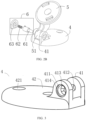
- a fixture including a mount 1 and a bracket 2.
- the bracket 2 is rotatably connected to the mount 1 and has a device, such as a camera, mounted thereon. After an angle of the bracket 2 is adjusted, relative positions of the mount 1 and the bracket 2 are locked by a nut 3 so that the bracket 2 is fixed at the adjusted angle.
- the nut 3 needs to be loosened and locked time and again to further adjust the angle of the bracket 2.
- This adjusting method not only is time-consuming and labor-consuming, but also sometimes involves use of tools such as a wrench, bringing inconvenience to the operation and tending to shorten a service life and cause failure of the nut 3 due to the repeated loosening and locking.
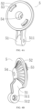
- a fixture according to an embodiment of the present disclosure includes a fixed member 4, a movable member 5 and an angle adjusting assembly 6.
- the fixed member 4 is configured to be fixedly connected to a base object (not shown).
- the fixed member 4 can be connected to the base object in various ways.
- the fixed member 4 includes a lower cap body 42, and a screw hole 421 provided in the lower cap body 42 such that the lower cap body 42 can be mounted on a base object such as a wall or a ceiling by a screw.
- the size and shape of the fixed member 4 and the number and arrangement mode of the screw holes 421 can be set freely according to the specific requirements.
- the movable member 5 is configured to be fixedly connected to the device, such as a camera, a projector, a display, or the like.
- the shape and size of the movable member 5 can be specifically designed for different shapes of devices.
- the movable member 5 includes an upper cap body 52.
- a catch 53 is provided on a mounting surface of the upper cap body 52 to connect the upper cap body 52 to the device in a snap-fit manner.
- the upper cap body 52 can be connected to the device by any other means, such as by a screw or by detachable connection.
- the upper cap body 52 is provided with a screw mounting hole 54 configured to enable the upper cap body 52 to be mounted on the base object by a screw.
- the screw mounting hole 54 By means of the arrangement of the screw mounting hole 54, the upper cap body 52 can be directly mounted on the base object, which can increase the mounting modes, improve the mounting flexibility, and satisfy mounting requirements of different devices.
- the fixed member 4 further includes a first bracket 41
- the movable member 5 further includes a second bracket 51.
- the first bracket 41 is connected to the lower cap body 42 and has two first support parts disposed oppositely; and the second bracket 51 is connected to the upper cap body 52 and has a second support part disposed between the two first support parts.
- the angle adjusting assembly 6 rotatably connects the movable member 5 to the fixed member 4, and is configured to be movable to a first position where the movable member 5 is rotated to any angle relative to the fixed member 4. In a second position, the angle adjusting assembly 6 enables the movable member 5 to be fixed at the any angle.
- the movable member 5 can be switched between a position adjustable state and a position fixed state, as long as the angle adjusting assembly 6 is movable between the first position and the second position. In this manner, the fixture according to this embodiment has the advantages of easy operation, reliable positioning, as well as a long service life and resistance to damage.
- the angle adjusting assembly 6 includes a pivot 61, a first limit structure on the pivot 61, and a second limit structure on the movable member 5.
- the pivot 61 is rotatably connected to the movable member 5 and movably connected to the fixed member 4.
- the pivot 61 penetrates through the two first support parts and the second support part to connect the fixed member 4 to the movable member 5.
- a first pivot hole 511 is provided in the second support part of the second bracket 51; and as shown in FIG. 3 , a second pivot hole 411 and a third pivot hole 412 are provided in the two first support parts of the first bracket 41, respectively.
- the first pivot hole 511, the second pivot hole 411 and the third pivot hole 412 are coaxially arranged, and the first pivot hole 511 is located between the second pivot hole 411 and the third pivot hole 412; and the pivot 61 penetrates through the first pivot hole 511, the second pivot hole 411 and the third pivot hole 412.
- the pivot 6 is movable between the second position and the first position along an axial direction of the pivot 61. That is, the pivot 61 is movable in the first pivot hole 511, the second pivot hole 411, and the third pivot hole 412.
- the first limit structure and the second limit structure are separated when the pivot 61 is moved to the first position so that the movable member 5 is rotatable to any angle about the pivot 61.
- the first limit structure and the second limit structure cooperate with each other when the pivot 61 is moved to the second position so that the movable member 5 is fixed at the any angle.
- the first limit structure is provided on an outer peripheral wall of the pivot 61
- the second limit structure is provided on a wall of the first pivot hole 511.
- the first limit structure and the second limit structure can cooperate with each other in various ways.
- the first limit structure includes a first boss 611 provided on the outer peripheral wall of the pivot 61.
- the second limit structure includes a second boss on the wall of the first pivot hole 511, and a first tooth portion 512 and a second tooth portion 612 are provided on two opposite end faces of the first boss 611 and the second boss, respectively.
- the first tooth portion 512 and the second tooth portion 612 are separated when the pivot 61 is moved to the first position, as shown in FIG. 6A , and engaged with each other when the pivot 61 is moved to the second position, as shown in FIG. 6B .
- the second bracket 51 can be rotated to any angle about the pivot 61.
- FIG. 6B when the first tooth portion 512 and the second tooth portion 612 are engaged, a degree of rotational freedom of the second bracket 51 is limited and thus is fixed relative to the pivot 61. It is easy to understand that the angular accuracy of the second bracket 51 in a circumferential direction of the pivot 61 depends on the number of teeth of the first tooth portion 512 and the second tooth portion 612, and the more teeth are provided, the higher the angular accuracy will be.
- the angle adjusting assembly 6 further includes an elastic member 62 which is elastically deformed when an external force is applied on the pivot 61, and which applies, when the external force is removed, an elastic force on the pivot 61 to make the pivot 61 return to the second position shown in FIG. 6B .
- an elastic member 62 By means of the elastic member 62, automatic reset of the pivot 61 can be realized. Therefore, to adjust the angle of the movable member 5, an external force can be applied on the pivot 61; and when the adjustment is completed, the movable member 5 can be fixed at the adjusted angle simply by releasing the external force, thereby further simplifying the adjustment.
- the elastic member 62 can have various structures, such as a compression spring.
- the angle adjusting means 6 further includes an end cap 63.
- the end cap 63 is disposed on the fixed member 4 and opposite to a first end face (the left end face of the pivot 61 shown in FIGs. 6A and 6B ) of the pivot 61 in the second pivot hole 411.
- the compression spring is provided in the second pivot hole 411 and located between the end cap 63 and the first end face, and is configured to generate compression deformation when an external force is applied on the pivot 61, and to apply, when the external force is removed, an elastic force on the pivot 61 to make the pivot return to the second position.
- a portion (at the right end of the pivot 61 shown in FIG. 6B ) of the pivot 61 remote from the first end face extends from the third pivot hole 412 to bear the external force.
- the pivot 61 when no external force is applied on the pivot 61, the pivot 61 is in the second position as shown in FIG. 6B ; when the extended portion of the pivot 61 is pressed, the pivot 61 is moved from the second position to the first position as shown in FIG. 6A ; and when the press is released, the pivot 61 automatically returns to the second position under an action of the compression spring.
- a step structure 414 is further provided in the second pivot hole 411.
- the end cap 63 can be fixed to the fixed member 4 by various methods, such as by adhesion, screws, ultrasonic welding, catches, etc.
- the angle adjusting assembly 6 further includes a first positioning structure 613 on the pivot 61, and a second positioning structure 413 in the second pivot hole 411.
- the first positioning structure 613 and the second positioning structure 413 cooperate with each other to define a degree of rotational freedom of the pivot 61 and thus achieve relative fixing of the pivot 61 to the fixed member 4.
- the first positioning structure 613 and the second positioning structure 413 can cooperate with each other in various ways.
- the first positioning structure 613 and the second positioning structure 413 are a convex portion on the outer peripheral wall of the pivot 61 and a concave portion in the second pivot hole 411, respectively, and the convex portion is fitted with the concave portion.
- the second positioning structure 413 can be disposed in the third pivot hole 412, or in both the second pivot hole 411 and the third pivot hole 412.
- the angle adjusting assembly 6 further includes a rotatable handle 7.
- the rotatable handle 7 is rotatably connected to the portion (i.e., the extended portion) of the pivot 61 remote from the first end face.
- the rotatable handle 7 has a first surface and a second surface which form an angle, and is configured such that when the rotatable handle 7 is rotated to a first angle as shown in 7A, the first surface is abutted against an end face of the third pivot hole 412 to drive the pivot 61 to move to the first position as shown in FIG.
- the rotatable handle 7 can bring more convenience to the operation. In practical applications, obviously, the rotatable handle 7 can adopt any other structure, as long as the pivot 61 can be moved.
- the movable member can be rotatably connected to the fixed member by means of the angle adjusting assembly.
- the angle adjusting assembly is configured to be movable to a first position where the movable member is rotatable to any angle relative to the fixed member, and to a second position where the movable member is fixed at the any angle.
- the movable member can be switched between a position adjustable state and a position fixed state, as long as the angle adjusting assembly is movable between the first position and the second position. Therefore, the fixture according to the embodiments of the present disclosure has the advantages of easy operation, reliable positioning, as well as a long service life and resistance to damage.
Landscapes
- Engineering & Computer Science (AREA)
- General Engineering & Computer Science (AREA)
- Mechanical Engineering (AREA)
- Pivots And Pivotal Connections (AREA)
- Accessories Of Cameras (AREA)
Applications Claiming Priority (2)
| Application Number | Priority Date | Filing Date | Title |
|---|---|---|---|
| CN202020531440.0U CN212390066U (zh) | 2020-04-13 | 2020-04-13 | 设备固定装置 |
| PCT/CN2021/086842 WO2021208891A1 (fr) | 2020-04-13 | 2021-04-13 | Dispositif de fixation |
Publications (2)
| Publication Number | Publication Date |
|---|---|
| EP4137734A1 true EP4137734A1 (fr) | 2023-02-22 |
| EP4137734A4 EP4137734A4 (fr) | 2024-04-10 |
Family
ID=74257071
Family Applications (1)
| Application Number | Title | Priority Date | Filing Date |
|---|---|---|---|
| EP21788205.9A Pending EP4137734A4 (fr) | 2020-04-13 | 2021-04-13 | Dispositif de fixation |
Country Status (3)
| Country | Link |
|---|---|
| EP (1) | EP4137734A4 (fr) |
| CN (1) | CN212390066U (fr) |
| WO (1) | WO2021208891A1 (fr) |
Cited By (1)
| Publication number | Priority date | Publication date | Assignee | Title |
|---|---|---|---|---|
| EP4477937A1 (fr) * | 2023-11-22 | 2024-12-18 | Siemens Healthineers AG | Dispositif de retenue pour maintenir une caméra et procédé d'alignement d'une caméra |
Families Citing this family (2)
| Publication number | Priority date | Publication date | Assignee | Title |
|---|---|---|---|---|
| CN212390066U (zh) * | 2020-04-13 | 2021-01-22 | 中兴通讯股份有限公司 | 设备固定装置 |
| CN120288420B (zh) * | 2025-06-13 | 2025-09-05 | 山东晶鑫机械装备有限公司 | 一种石膏板自动横向皮带机 |
Family Cites Families (9)
| Publication number | Priority date | Publication date | Assignee | Title |
|---|---|---|---|---|
| NZ213967A (en) * | 1985-09-16 | 1988-10-28 | Read Eze Systems Ltd | Adjustable support for document holder with adjustable cursor |
| US7303171B1 (en) * | 2006-11-21 | 2007-12-04 | Supa Technology Co., Ltd. | Adjustable fixing mount |
| TWM349441U (en) * | 2008-06-17 | 2009-01-21 | Da-Shuo Zhang | Improved structure of disassembly-type suction cup |
| GB2489689B (en) * | 2011-04-01 | 2016-03-09 | Sioned Helen Owen | Universal filming mount for activities |
| US9326496B2 (en) * | 2014-06-19 | 2016-05-03 | Mark Chmura | Adjustable tubular holding apparatus particularly useful in fishing |
| CN206708677U (zh) * | 2017-04-19 | 2017-12-05 | 东莞市兴阳电子有限公司 | 一种角度可调的分体式电脑显示屏支架转轴 |
| CN210069343U (zh) * | 2019-04-24 | 2020-02-14 | 上海东普信息科技有限公司 | 一种单目摄像头安装座 |
| CN110515257A (zh) * | 2019-08-26 | 2019-11-29 | 深圳市旅行家科技有限公司 | 一种方便调节角度的摄影补光灯及其角度调节结构 |
| CN212390066U (zh) * | 2020-04-13 | 2021-01-22 | 中兴通讯股份有限公司 | 设备固定装置 |
-
2020
- 2020-04-13 CN CN202020531440.0U patent/CN212390066U/zh active Active
-
2021
- 2021-04-13 EP EP21788205.9A patent/EP4137734A4/fr active Pending
- 2021-04-13 WO PCT/CN2021/086842 patent/WO2021208891A1/fr not_active Ceased
Cited By (1)
| Publication number | Priority date | Publication date | Assignee | Title |
|---|---|---|---|---|
| EP4477937A1 (fr) * | 2023-11-22 | 2024-12-18 | Siemens Healthineers AG | Dispositif de retenue pour maintenir une caméra et procédé d'alignement d'une caméra |
Also Published As
| Publication number | Publication date |
|---|---|
| WO2021208891A1 (fr) | 2021-10-21 |
| EP4137734A4 (fr) | 2024-04-10 |
| CN212390066U (zh) | 2021-01-22 |
Similar Documents
| Publication | Publication Date | Title |
|---|---|---|
| EP4137734A1 (fr) | Dispositif de fixation | |
| EP3214493A1 (fr) | Ensemble de limitation de lentille, corps de caméra et caméra | |
| US7445346B2 (en) | Projection equipment support system | |
| JP3221114U (ja) | 支持フレーム | |
| CN111911751B (zh) | 摄像机支架 | |
| TWM620642U (zh) | 用於周邊裝置之安裝座 | |
| US20050218273A1 (en) | Universal adaptor used in display | |
| CN205001802U (zh) | 连动结构及具有该连动结构的支架 | |
| US3929365A (en) | Fluorescent tube changing device | |
| WO2007080897A1 (fr) | Dispositif extensible | |
| JP6188901B1 (ja) | フリーロックジョイント | |
| CN221381133U (zh) | 麦克风支架的快拆装置 | |
| CN216803404U (zh) | 一种位置可调支架 | |
| CN106254996B (zh) | 用于调节音响倾角的装置 | |
| CN217422758U (zh) | 万向怪手支架 | |
| CN205101792U (zh) | 摄像器材支架机构和摄像系统 | |
| JPH08261248A (ja) | 端末を取り付けるための器具及びその方法 | |
| CN104696252B (zh) | 操作台结构及电风扇 | |
| CN212170407U (zh) | 一种模块化软体机器人 | |
| CN222032878U (zh) | 一种急救箱挂墙结构 | |
| CN219212951U (zh) | 一种用于压缩机的限位夹持装置 | |
| CN222067986U (zh) | 对接锁紧结构 | |
| CN218691210U (zh) | 一种涂布烘箱均匀干燥装置 | |
| CN222103335U (zh) | 一种投影装置 | |
| CN220102602U (zh) | 一种视觉检测设备安装云台 |
Legal Events
| Date | Code | Title | Description |
|---|---|---|---|
| STAA | Information on the status of an ep patent application or granted ep patent |
Free format text: STATUS: THE INTERNATIONAL PUBLICATION HAS BEEN MADE |
|
| PUAI | Public reference made under article 153(3) epc to a published international application that has entered the european phase |
Free format text: ORIGINAL CODE: 0009012 |
|
| STAA | Information on the status of an ep patent application or granted ep patent |
Free format text: STATUS: REQUEST FOR EXAMINATION WAS MADE |
|
| 17P | Request for examination filed |
Effective date: 20220414 |
|
| AK | Designated contracting states |
Kind code of ref document: A1 Designated state(s): AL AT BE BG CH CY CZ DE DK EE ES FI FR GB GR HR HU IE IS IT LI LT LU LV MC MK MT NL NO PL PT RO RS SE SI SK SM TR |
|
| DAV | Request for validation of the european patent (deleted) | ||
| DAX | Request for extension of the european patent (deleted) | ||
| A4 | Supplementary search report drawn up and despatched |
Effective date: 20240313 |
|
| RIC1 | Information provided on ipc code assigned before grant |
Ipc: F16M 11/04 20060101ALI20240306BHEP Ipc: F16M 11/10 20060101ALI20240306BHEP Ipc: F16M 13/02 20060101AFI20240306BHEP |
|
| STAA | Information on the status of an ep patent application or granted ep patent |
Free format text: STATUS: EXAMINATION IS IN PROGRESS |
|
| 17Q | First examination report despatched |
Effective date: 20250123 |