EP4137735A1 - Dispositif de surveillance et procédé de fonctionnement d'un systeme capteur - Google Patents
Dispositif de surveillance et procédé de fonctionnement d'un systeme capteur Download PDFInfo
- Publication number
- EP4137735A1 EP4137735A1 EP21191730.7A EP21191730A EP4137735A1 EP 4137735 A1 EP4137735 A1 EP 4137735A1 EP 21191730 A EP21191730 A EP 21191730A EP 4137735 A1 EP4137735 A1 EP 4137735A1
- Authority
- EP
- European Patent Office
- Prior art keywords
- switching
- bridging
- object detection
- monitoring device
- detection signal
- Prior art date
- Legal status (The legal status is an assumption and is not a legal conclusion. Google has not performed a legal analysis and makes no representation as to the accuracy of the status listed.)
- Granted
Links
Images

Classifications
-
- F—MECHANICAL ENGINEERING; LIGHTING; HEATING; WEAPONS; BLASTING
- F16—ENGINEERING ELEMENTS AND UNITS; GENERAL MEASURES FOR PRODUCING AND MAINTAINING EFFECTIVE FUNCTIONING OF MACHINES OR INSTALLATIONS; THERMAL INSULATION IN GENERAL
- F16P—SAFETY DEVICES IN GENERAL; SAFETY DEVICES FOR PRESSES
- F16P3/00—Safety devices acting in conjunction with the control or operation of a machine; Control arrangements requiring the simultaneous use of two or more parts of the body
- F16P3/12—Safety devices acting in conjunction with the control or operation of a machine; Control arrangements requiring the simultaneous use of two or more parts of the body with means, e.g. feelers, which in case of the presence of a body part of a person in or near the danger zone influence the control or operation of the machine
- F16P3/14—Safety devices acting in conjunction with the control or operation of a machine; Control arrangements requiring the simultaneous use of two or more parts of the body with means, e.g. feelers, which in case of the presence of a body part of a person in or near the danger zone influence the control or operation of the machine the means being photocells or other devices sensitive without mechanical contact
- F16P3/144—Safety devices acting in conjunction with the control or operation of a machine; Control arrangements requiring the simultaneous use of two or more parts of the body with means, e.g. feelers, which in case of the presence of a body part of a person in or near the danger zone influence the control or operation of the machine the means being photocells or other devices sensitive without mechanical contact using light grids
Definitions
- the invention relates to a monitoring device and a method for operating a sensor arrangement.
- the monitoring device is generally suitable for use in the field of security technology and includes a security sensor, for example a light curtain, which typically has a series arrangement of transmitters emitting light beams in a first housing and a series arrangement of receivers receiving light beams in a second housing.
- a security sensor for example a light curtain, which typically has a series arrangement of transmitters emitting light beams in a first housing and a series arrangement of receivers receiving light beams in a second housing.
- a monitoring function is implemented in such a way that the received signals of the receivers are evaluated in an evaluation unit of the light curtain and thus a binary object detection signal is generated, the switching states of which indicate whether an object is present in a protective field monitored by the light curtain or not. If an object is detected in the protective field, the object detection signal thus generated triggers a safety function, for example a dangerous system monitored by the light curtain is shut down.
- a typical application for such a sensor arrangement is access protection to a hazardous area of a hazardous installation. Access to the danger area is via a conveyor unit, which is monitored by the light curtain.
- the monitoring function of the light curtain should then be designed in such a way that the passage of safety-critical objects, in particular people, is detected by the light curtain, so that the safety function is triggered to avoid dangerous situations.
- Permitted objects such as workpieces or loads that have to be fed to the machine or system to carry out work processes, should not trigger the safety function, however, in order to avoid unnecessary system downtimes.
- a muting function is provided for the sensor arrangement in a known manner.
- muting sensors can be arranged upstream of the light curtain in the conveying direction of the conveying unit, with which permissible objects are detected. If this is the case, the monitoring function of the light curtain is muted for a specified time, i.e. bypassed, so that the permitted objects can pass through the light curtain without it generating a switching signal that triggers the safety function.
- SPG Smart Process Gating
- MLC 530 SPG safety light curtain from Leuze electronic GmbH + Co. KG.
- a first control signal is provided by a system controller, which controls the conveyor unit in particular.
- This first control signal is generated when a permissible object is so close in front of the light curtain that no person can slip between the permissible object and the light curtain.
- the maximum distance between the permitted object and the light curtain is 200 millimeters.
- a second control signal is then generated by the light curtain itself if it registers an object intrusion in the protective field after the first control signal.
- the muting function is only activated if the first control signal is registered within a first time interval ⁇ t 1 monitored by a bridging device.
- the bridging of the light curtain is then maintained for a specified time, which is selected in such a way that the permissible object has left the protective field again after this time has elapsed.
- the muting function is ended when the deactivation of the two control signals is registered within a second time interval ⁇ t 2 monitored by the bridging device.
- the light curtain is switched to a secure locking state, which triggers the safety function and thus shuts down the system.
- the deactivation of the control signals is not registered within the second time interval ⁇ t 2 .
- the invention is based on the object of providing a monitoring device with which safe danger area monitoring of a system is implemented without unnecessarily restricting its availability.
- the object of the invention is to increase the functionality and safety for a sensor arrangement of the type mentioned at the outset when monitoring danger zones.
- the invention relates to a monitoring device for monitoring a danger area in a system, with a safety sensor monitoring a protective field.
- the safety sensor generates a binary object detection signal that assumes the "on” switching state when an object is present in the protective field. With the object detection signal in the "on” switching state, a safety function for the system is triggered.
- a bridging device is provided, which is supplied with the object detection signal and a binary switching signal with switching states “on” and “off”.
- a bridging cycle within which the safety function of the safety sensor is bridged, is only activated if the switching signal changes to the "on” switching state and the object detection signal changes to the "on” switching state within a time interval monitored by the bridging device. The bridging is maintained until both the switching signal and the object detection signal have changed to the "off” switching state, with the time difference between these signal changes being arbitrary and not monitored by the bridging device.
- the invention also relates to a method for operating a monitoring device.
- the safety sensor of the monitoring device With the safety sensor of the monitoring device according to the invention, failsafe monitoring of a hazardous area of a system is ensured.
- the safety sensor is generally used to monitor a protective field, which can be designed in the form of a surface or a spatial area.
- the safety sensor can be a light curtain, a surface distance sensor or a camera sensor.
- the safety sensor is preferably designed as an optical sensor.
- the safety sensor is an area distance sensor, it can also be designed as a radar sensor.
- the functionality of the safety sensor is generally such that it generates a binary object detection signal depending on whether an object is registered in the protective field or not.
- the safety sensor has an evaluation unit in which the object detection signal is generated, the object detection signal being fed to the system via at least one switching output.
- a safety function is triggered in particular by switching off the switching output, in particular the monitored system is shut down.
- a bridging device in the monitoring device according to the invention, which controls bridging, ie muting.
- a muting mode the safety function of the safety sensor is bypassed so that an object intrusion in the protective field does not trigger the safety function.
- partial muting can also be provided, in which only part of the protective field is bypassed.
- Muting ensures that permissible, non-safety-critical objects such as transport goods can be fed into the monitored system without the safety sensor triggering the safety function.
- permissible objects are fed in by means of a conveyor unit.
- the bridging device controls the muting function depending on the object detection signal and a switching signal, which is read in particular by a control unit.
- control unit can be formed by a system controller that controls the system.
- control unit can be formed by the controller of the conveyor unit.
- a bridging cycle ie bridging the safety sensor for a specific time, is only triggered if the control signal and the object detection signal change to the "on" switching state within a time interval monitored by the monitoring device.
- the switching signal first changes to the "on" switching state as a muting request and then, within the time interval, which is typically 4 seconds, the object detection signal changes to the "on" switching state as a muting confirmation.
- the switching signal then advantageously changes to the "on" switching state when a permissible object is arranged close in front of the safety sensor, so that no one can step between the permissible object and the protective field of the safety sensor.
- the safety sensor is switched to a secure locking state and the system is shut down.
- the bridging of the safety sensor is maintained until both the object detection signal and the switching signal have switched back to the "off" switching state.
- the transition of the object detection signal to the "off" switching state indicates that there is no longer any object in the protective field. In particular, it is signaled that the permitted object has left the protective field. This fulfills the essential condition for canceling the muting function.
- the transition of the switching signal to the "off" switching state represents the second condition for canceling the muting function.
- the times of the transitions of the switching states of the switching signal and the object detection signal to the "off" switching state can be at any point in relation to one another, with the time interval between these transitions also not being monitored by the monitoring device.
- the safety sensor Since this time interval is not monitored by the bridging device, the safety sensor does not switch to the secure locking state if the time interval is not met, ie the system is not shut down. This increases the availability of the system without reducing the safety of the danger area protection in a dangerous manner.
- the monitoring device has error control means for error control of the switching signal.
- the safety sensor already has a fail-safe design, which is implemented in particular by a fail-safe evaluation unit, for example in
- Error checking of the switching signal also ensures that the switching signal is read in in a fail-safe manner.
- the fault control means is used to monitor short circuits and/or monitor for the presence of stuck-at faults and/or monitor for the presence of a periodic oscillation of the switching signal.
- no bridging cycle is activated when an error in the switching signal is detected in the monitoring device.
- the safety of the monitoring device is further increased by the safety sensor being transferred to a secure locking state in the bridging unit when an error in the switching signal is detected.
- a new bridging cycle is only activated if the previous bridging cycle was correctly ended by the monitoring device registering both a change in the switching signal to the “off” switching state and a change in the object detection signal to the “off” switching state .
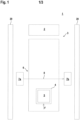
- FIG 1 shows a schematic of an example of the monitoring device 1 according to the invention.
- the monitoring device 1 is used to protect access to a danger area on a dangerous installation 2 .
- Access to the danger area is via a conveyor 3, the conveyor belt of which is moved in the direction of movement marked F in order to convey transport goods 5 arranged on pallets 4 into the danger area.
- transported goods 5 can be taken out of the danger area in the same way.
- the conveyor 3 is protected by fencing 20 attached to the side.
- the monitoring device 1 includes a safety sensor 6 in the form of an optical sensor.
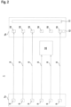
- the safety sensor 6 is designed as a light curtain ( figure 2 ).
- the light curtain has a series arrangement of transmitters 9 emitting light beams 8 in a first housing 7a and a series arrangement of receivers 10 in a second housing 7b.
- the light beams 8 define beam axes of the light curtain and span a flat protective field that is oriented in a vertical plane and thus runs perpendicular to the horizontal surface of the conveyor belt of the conveyor device 3 .
- the transmitters 9 are activated one after the other cyclically by means of a transmitter control, not shown.
- the receivers 10 are optically synchronized with the transmitters 9 in a known manner.
- Each transmitter 9 forms a beam axis of the light curtain with the assigned receiver 10 .
- the received signals generated in the receivers 10 are evaluated in an evaluation unit 11 to generate a binary object detection signal.
- the switching states "on” or “off” of the object detection signal indicate whether an object 12 is in the protective field or not.
- the evaluation unit 11 has a redundant, preferably two-channel structure.
- a safety function is triggered by the object detection signal, in particular the hazardous system 2 is shut down.
- the object detection signal is output to the system 2 via a switching output 13 .
- a redundant arrangement of switching outputs can also be provided.
- the safety sensor 6 can be muted, i.e. bypassed, if a permissible object 12 such as, for example, transported goods 5 stored on a plate 4 passes the protective field of the safety sensor 6 . By bridging the safety sensor 6, it does not trigger a safety function when the permissible object 12 passes the protective field and the transported goods 5 can be fed to the system 2 without the system being shut down.
- the muting is controlled in a bypass device 1 , which is part of the evaluation unit 11 of the safety sensor 6 in the present case.
- the muting is controlled as a function of the object detection signals from the safety sensor 6 and switching signals from an external control unit, which is formed, for example, from the system controller of the system 2 or the controller of the conveyor unit.
- the switching signal is switched to the "on" switching state (t 1 in Figure 3a ).
- the time difference between t 1 and t 2 is monitored. If the time difference t 2 - t 1 is within a time interval ⁇ t specified in the monitoring device 1, a bridging cycle i.e. muting activated, i.e. the muting signal changes from state 0 to state 1 (t 2 in Figure 3c ).
- the safety sensor 6 is switched to a secure locking state, ie the switching output or outputs are switched off so that the safety function is triggered and the system 2 is shut down.
- the muting remains activated as long as the permitted object 12 passes the protective field, i.e. no safety function is triggered that shuts down the system 2.
- the muting signal changes to the 0 state (t 4 in the Figures 3b, 3c ).
- the condition for ending the bypass cycle is that both the object detection signal and the switching signal change to the switching state "off".
- the time difference between these signal changes, here t 4 -t 3 is not monitored in the bridging unit 1 and is therefore arbitrary.
- the bridging unit monitors whether a bridging cycle has ended correctly by checking whether both the object detection signal and the switching signal have switched to the “off” switching state. Only if this is the case can a new bypass cycle be started.
- the bridging unit 1 advantageously has error control means for error control of the switching signal.
- short-circuit monitoring is carried out to determine whether there is a short-circuit between the input via which the switching signal is read into the bridging device 1, ie the evaluation unit 11 of the safety sensor 6, and other inputs or outputs of the safety sensor 6.
- a suitable test circuit can be integrated in the monitoring device 1 for this purpose.
- the switching signal is also checked for stuck-at errors, ie whether there is an error at the input via which the switching signal is read in such a way that the signal there no longer changes. This can be tested, for example, using test pulses that are output by the bridging device 1 to the input and are read back by the bridging device.
- the safety sensor 6 is switched to a secure locking state.
Landscapes
- Engineering & Computer Science (AREA)
- General Engineering & Computer Science (AREA)
- Mechanical Engineering (AREA)
- Geophysics And Detection Of Objects (AREA)
Priority Applications (1)
| Application Number | Priority Date | Filing Date | Title |
|---|---|---|---|
| EP21191730.7A EP4137735B1 (fr) | 2021-08-17 | 2021-08-17 | Dispositif de surveillance et procédé de fonctionnement d'un systeme capteur |
Applications Claiming Priority (1)
| Application Number | Priority Date | Filing Date | Title |
|---|---|---|---|
| EP21191730.7A EP4137735B1 (fr) | 2021-08-17 | 2021-08-17 | Dispositif de surveillance et procédé de fonctionnement d'un systeme capteur |
Publications (2)
| Publication Number | Publication Date |
|---|---|
| EP4137735A1 true EP4137735A1 (fr) | 2023-02-22 |
| EP4137735B1 EP4137735B1 (fr) | 2023-12-06 |
Family
ID=77367362
Family Applications (1)
| Application Number | Title | Priority Date | Filing Date |
|---|---|---|---|
| EP21191730.7A Active EP4137735B1 (fr) | 2021-08-17 | 2021-08-17 | Dispositif de surveillance et procédé de fonctionnement d'un systeme capteur |
Country Status (1)
| Country | Link |
|---|---|
| EP (1) | EP4137735B1 (fr) |
Citations (1)
| Publication number | Priority date | Publication date | Assignee | Title |
|---|---|---|---|---|
| US20080179504A1 (en) * | 2007-01-25 | 2008-07-31 | Keyence Corporation | Multi-Optical Axis Photoelectric Sensor |
-
2021
- 2021-08-17 EP EP21191730.7A patent/EP4137735B1/fr active Active
Patent Citations (1)
| Publication number | Priority date | Publication date | Assignee | Title |
|---|---|---|---|---|
| US20080179504A1 (en) * | 2007-01-25 | 2008-07-31 | Keyence Corporation | Multi-Optical Axis Photoelectric Sensor |
Also Published As
| Publication number | Publication date |
|---|---|
| EP4137735B1 (fr) | 2023-12-06 |
Similar Documents
| Publication | Publication Date | Title |
|---|---|---|
| EP3910230B1 (fr) | Dispositif de surveillance | |
| DE102009048111B4 (de) | Sicherheitssensor | |
| EP2017524B1 (fr) | Barrière lumineuse | |
| EP1398729B1 (fr) | Système de détecteur et procédé de détection | |
| EP2037297B1 (fr) | Détection d'objet et barrière lumineuse | |
| EP3885635B1 (fr) | Dispositif de surveillance permettant de sécuriser l'accès à une zone dangereuse à l'aide d'un capteur de sécurité | |
| DE102008004941A1 (de) | Sicherheitsanordnung und Verfahren | |
| DE102009055990B4 (de) | Überwachungssensor | |
| EP3415804A1 (fr) | Dispositif de sécurité | |
| DE3932665A1 (de) | Ueberwachungsvorrichtung | |
| EP4116620B1 (fr) | Dispositif de surveillance et procédé de fonctionnement d'un dispositif de surveillance | |
| EP4137735B1 (fr) | Dispositif de surveillance et procédé de fonctionnement d'un systeme capteur | |
| EP3886068B1 (fr) | Dispositif de surveillance et procédé de fonctionnement un dispositif de surveillance | |
| EP3594553A1 (fr) | Dispositif de surveillance d'une zone de danger | |
| EP3875993B1 (fr) | Dispositif capteur et procédé de fonctionnement d'un dispositif capteur | |
| DE4041550C2 (de) | Sicherheitseinrichtung mit mindestens einem berührungslosen Geber | |
| EP3910228B1 (fr) | Dispositif de surveillance et procédé de fonctionnement un dispositif de surveillance | |
| DE202019103376U1 (de) | Vorrichtung | |
| DE202017107058U1 (de) | Sicherheitssteuerung und Sicherheitssystem | |
| DE202012102549U1 (de) | Sicherheitssensor | |
| EP3910227B1 (fr) | Dispositif de surveillance et procédé de fonctionnement d'un dispositif de surveillance | |
| EP4047256B1 (fr) | Dispositif de surveillance et procédé de sécurisation d'une zone dangereuse au moyen d'un dispositif de surveillance | |
| EP3910229B1 (fr) | Dispositif de surveillance | |
| EP3879312B1 (fr) | Capteur optique | |
| EP4354010B1 (fr) | Dispositif de surveillance |
Legal Events
| Date | Code | Title | Description |
|---|---|---|---|
| PUAI | Public reference made under article 153(3) epc to a published international application that has entered the european phase |
Free format text: ORIGINAL CODE: 0009012 |
|
| STAA | Information on the status of an ep patent application or granted ep patent |
Free format text: STATUS: REQUEST FOR EXAMINATION WAS MADE |
|
| 17P | Request for examination filed |
Effective date: 20220406 |
|
| AK | Designated contracting states |
Kind code of ref document: A1 Designated state(s): AL AT BE BG CH CY CZ DE DK EE ES FI FR GB GR HR HU IE IS IT LI LT LU LV MC MK MT NL NO PL PT RO RS SE SI SK SM TR |
|
| GRAP | Despatch of communication of intention to grant a patent |
Free format text: ORIGINAL CODE: EPIDOSNIGR1 |
|
| STAA | Information on the status of an ep patent application or granted ep patent |
Free format text: STATUS: GRANT OF PATENT IS INTENDED |
|
| INTG | Intention to grant announced |
Effective date: 20230804 |
|
| GRAS | Grant fee paid |
Free format text: ORIGINAL CODE: EPIDOSNIGR3 |
|
| GRAA | (expected) grant |
Free format text: ORIGINAL CODE: 0009210 |
|
| STAA | Information on the status of an ep patent application or granted ep patent |
Free format text: STATUS: THE PATENT HAS BEEN GRANTED |
|
| AK | Designated contracting states |
Kind code of ref document: B1 Designated state(s): AL AT BE BG CH CY CZ DE DK EE ES FI FR GB GR HR HU IE IS IT LI LT LU LV MC MK MT NL NO PL PT RO RS SE SI SK SM TR |
|
| REG | Reference to a national code |
Ref country code: GB Ref legal event code: FG4D Free format text: NOT ENGLISH |
|
| REG | Reference to a national code |
Ref country code: CH Ref legal event code: EP |
|
| REG | Reference to a national code |
Ref country code: DE Ref legal event code: R096 Ref document number: 502021002111 Country of ref document: DE |
|
| REG | Reference to a national code |
Ref country code: IE Ref legal event code: FG4D Free format text: LANGUAGE OF EP DOCUMENT: GERMAN |
|
| REG | Reference to a national code |
Ref country code: LT Ref legal event code: MG9D |
|
| PG25 | Lapsed in a contracting state [announced via postgrant information from national office to epo] |
Ref country code: GR Free format text: LAPSE BECAUSE OF FAILURE TO SUBMIT A TRANSLATION OF THE DESCRIPTION OR TO PAY THE FEE WITHIN THE PRESCRIBED TIME-LIMIT Effective date: 20240307 |
|
| REG | Reference to a national code |
Ref country code: NL Ref legal event code: MP Effective date: 20231206 |
|
| PG25 | Lapsed in a contracting state [announced via postgrant information from national office to epo] |
Ref country code: LT Free format text: LAPSE BECAUSE OF FAILURE TO SUBMIT A TRANSLATION OF THE DESCRIPTION OR TO PAY THE FEE WITHIN THE PRESCRIBED TIME-LIMIT Effective date: 20231206 |
|
| PG25 | Lapsed in a contracting state [announced via postgrant information from national office to epo] |
Ref country code: ES Free format text: LAPSE BECAUSE OF FAILURE TO SUBMIT A TRANSLATION OF THE DESCRIPTION OR TO PAY THE FEE WITHIN THE PRESCRIBED TIME-LIMIT Effective date: 20231206 |
|
| PG25 | Lapsed in a contracting state [announced via postgrant information from national office to epo] |
Ref country code: LT Free format text: LAPSE BECAUSE OF FAILURE TO SUBMIT A TRANSLATION OF THE DESCRIPTION OR TO PAY THE FEE WITHIN THE PRESCRIBED TIME-LIMIT Effective date: 20231206 Ref country code: GR Free format text: LAPSE BECAUSE OF FAILURE TO SUBMIT A TRANSLATION OF THE DESCRIPTION OR TO PAY THE FEE WITHIN THE PRESCRIBED TIME-LIMIT Effective date: 20240307 Ref country code: ES Free format text: LAPSE BECAUSE OF FAILURE TO SUBMIT A TRANSLATION OF THE DESCRIPTION OR TO PAY THE FEE WITHIN THE PRESCRIBED TIME-LIMIT Effective date: 20231206 Ref country code: BG Free format text: LAPSE BECAUSE OF FAILURE TO SUBMIT A TRANSLATION OF THE DESCRIPTION OR TO PAY THE FEE WITHIN THE PRESCRIBED TIME-LIMIT Effective date: 20240306 |
|
| PG25 | Lapsed in a contracting state [announced via postgrant information from national office to epo] |
Ref country code: NL Free format text: LAPSE BECAUSE OF FAILURE TO SUBMIT A TRANSLATION OF THE DESCRIPTION OR TO PAY THE FEE WITHIN THE PRESCRIBED TIME-LIMIT Effective date: 20231206 |
|
| PG25 | Lapsed in a contracting state [announced via postgrant information from national office to epo] |
Ref country code: SE Free format text: LAPSE BECAUSE OF FAILURE TO SUBMIT A TRANSLATION OF THE DESCRIPTION OR TO PAY THE FEE WITHIN THE PRESCRIBED TIME-LIMIT Effective date: 20231206 Ref country code: RS Free format text: LAPSE BECAUSE OF FAILURE TO SUBMIT A TRANSLATION OF THE DESCRIPTION OR TO PAY THE FEE WITHIN THE PRESCRIBED TIME-LIMIT Effective date: 20231206 Ref country code: NO Free format text: LAPSE BECAUSE OF FAILURE TO SUBMIT A TRANSLATION OF THE DESCRIPTION OR TO PAY THE FEE WITHIN THE PRESCRIBED TIME-LIMIT Effective date: 20240306 Ref country code: NL Free format text: LAPSE BECAUSE OF FAILURE TO SUBMIT A TRANSLATION OF THE DESCRIPTION OR TO PAY THE FEE WITHIN THE PRESCRIBED TIME-LIMIT Effective date: 20231206 Ref country code: LV Free format text: LAPSE BECAUSE OF FAILURE TO SUBMIT A TRANSLATION OF THE DESCRIPTION OR TO PAY THE FEE WITHIN THE PRESCRIBED TIME-LIMIT Effective date: 20231206 Ref country code: HR Free format text: LAPSE BECAUSE OF FAILURE TO SUBMIT A TRANSLATION OF THE DESCRIPTION OR TO PAY THE FEE WITHIN THE PRESCRIBED TIME-LIMIT Effective date: 20231206 |
|
| PG25 | Lapsed in a contracting state [announced via postgrant information from national office to epo] |
Ref country code: IS Free format text: LAPSE BECAUSE OF FAILURE TO SUBMIT A TRANSLATION OF THE DESCRIPTION OR TO PAY THE FEE WITHIN THE PRESCRIBED TIME-LIMIT Effective date: 20240406 |
|
| PG25 | Lapsed in a contracting state [announced via postgrant information from national office to epo] |
Ref country code: CZ Free format text: LAPSE BECAUSE OF FAILURE TO SUBMIT A TRANSLATION OF THE DESCRIPTION OR TO PAY THE FEE WITHIN THE PRESCRIBED TIME-LIMIT Effective date: 20231206 |
|
| PG25 | Lapsed in a contracting state [announced via postgrant information from national office to epo] |
Ref country code: SK Free format text: LAPSE BECAUSE OF FAILURE TO SUBMIT A TRANSLATION OF THE DESCRIPTION OR TO PAY THE FEE WITHIN THE PRESCRIBED TIME-LIMIT Effective date: 20231206 |
|
| PG25 | Lapsed in a contracting state [announced via postgrant information from national office to epo] |
Ref country code: SM Free format text: LAPSE BECAUSE OF FAILURE TO SUBMIT A TRANSLATION OF THE DESCRIPTION OR TO PAY THE FEE WITHIN THE PRESCRIBED TIME-LIMIT Effective date: 20231206 Ref country code: SK Free format text: LAPSE BECAUSE OF FAILURE TO SUBMIT A TRANSLATION OF THE DESCRIPTION OR TO PAY THE FEE WITHIN THE PRESCRIBED TIME-LIMIT Effective date: 20231206 Ref country code: RO Free format text: LAPSE BECAUSE OF FAILURE TO SUBMIT A TRANSLATION OF THE DESCRIPTION OR TO PAY THE FEE WITHIN THE PRESCRIBED TIME-LIMIT Effective date: 20231206 Ref country code: IT Free format text: LAPSE BECAUSE OF FAILURE TO SUBMIT A TRANSLATION OF THE DESCRIPTION OR TO PAY THE FEE WITHIN THE PRESCRIBED TIME-LIMIT Effective date: 20231206 Ref country code: IS Free format text: LAPSE BECAUSE OF FAILURE TO SUBMIT A TRANSLATION OF THE DESCRIPTION OR TO PAY THE FEE WITHIN THE PRESCRIBED TIME-LIMIT Effective date: 20240406 Ref country code: EE Free format text: LAPSE BECAUSE OF FAILURE TO SUBMIT A TRANSLATION OF THE DESCRIPTION OR TO PAY THE FEE WITHIN THE PRESCRIBED TIME-LIMIT Effective date: 20231206 Ref country code: CZ Free format text: LAPSE BECAUSE OF FAILURE TO SUBMIT A TRANSLATION OF THE DESCRIPTION OR TO PAY THE FEE WITHIN THE PRESCRIBED TIME-LIMIT Effective date: 20231206 |
|
| PG25 | Lapsed in a contracting state [announced via postgrant information from national office to epo] |
Ref country code: PT Free format text: LAPSE BECAUSE OF FAILURE TO SUBMIT A TRANSLATION OF THE DESCRIPTION OR TO PAY THE FEE WITHIN THE PRESCRIBED TIME-LIMIT Effective date: 20240408 Ref country code: PL Free format text: LAPSE BECAUSE OF FAILURE TO SUBMIT A TRANSLATION OF THE DESCRIPTION OR TO PAY THE FEE WITHIN THE PRESCRIBED TIME-LIMIT Effective date: 20231206 |
|
| PG25 | Lapsed in a contracting state [announced via postgrant information from national office to epo] |
Ref country code: PT Free format text: LAPSE BECAUSE OF FAILURE TO SUBMIT A TRANSLATION OF THE DESCRIPTION OR TO PAY THE FEE WITHIN THE PRESCRIBED TIME-LIMIT Effective date: 20240408 Ref country code: PL Free format text: LAPSE BECAUSE OF FAILURE TO SUBMIT A TRANSLATION OF THE DESCRIPTION OR TO PAY THE FEE WITHIN THE PRESCRIBED TIME-LIMIT Effective date: 20231206 |
|
| REG | Reference to a national code |
Ref country code: DE Ref legal event code: R097 Ref document number: 502021002111 Country of ref document: DE |
|
| PG25 | Lapsed in a contracting state [announced via postgrant information from national office to epo] |
Ref country code: DK Free format text: LAPSE BECAUSE OF FAILURE TO SUBMIT A TRANSLATION OF THE DESCRIPTION OR TO PAY THE FEE WITHIN THE PRESCRIBED TIME-LIMIT Effective date: 20231206 |
|
| PLBE | No opposition filed within time limit |
Free format text: ORIGINAL CODE: 0009261 |
|
| STAA | Information on the status of an ep patent application or granted ep patent |
Free format text: STATUS: NO OPPOSITION FILED WITHIN TIME LIMIT |
|
| P01 | Opt-out of the competence of the unified patent court (upc) registered |
Free format text: CASE NUMBER: APP_51080/2024 Effective date: 20240910 |
|
| PG25 | Lapsed in a contracting state [announced via postgrant information from national office to epo] |
Ref country code: SI Free format text: LAPSE BECAUSE OF FAILURE TO SUBMIT A TRANSLATION OF THE DESCRIPTION OR TO PAY THE FEE WITHIN THE PRESCRIBED TIME-LIMIT Effective date: 20231206 |
|
| PG25 | Lapsed in a contracting state [announced via postgrant information from national office to epo] |
Ref country code: SI Free format text: LAPSE BECAUSE OF FAILURE TO SUBMIT A TRANSLATION OF THE DESCRIPTION OR TO PAY THE FEE WITHIN THE PRESCRIBED TIME-LIMIT Effective date: 20231206 Ref country code: DK Free format text: LAPSE BECAUSE OF FAILURE TO SUBMIT A TRANSLATION OF THE DESCRIPTION OR TO PAY THE FEE WITHIN THE PRESCRIBED TIME-LIMIT Effective date: 20231206 |
|
| 26N | No opposition filed |
Effective date: 20240909 |
|
| REG | Reference to a national code |
Ref country code: CH Ref legal event code: PL |
|
| PG25 | Lapsed in a contracting state [announced via postgrant information from national office to epo] |
Ref country code: LU Free format text: LAPSE BECAUSE OF NON-PAYMENT OF DUE FEES Effective date: 20240817 |
|
| PG25 | Lapsed in a contracting state [announced via postgrant information from national office to epo] |
Ref country code: CH Free format text: LAPSE BECAUSE OF NON-PAYMENT OF DUE FEES Effective date: 20240831 Ref country code: MC Free format text: LAPSE BECAUSE OF FAILURE TO SUBMIT A TRANSLATION OF THE DESCRIPTION OR TO PAY THE FEE WITHIN THE PRESCRIBED TIME-LIMIT Effective date: 20231206 |
|
| REG | Reference to a national code |
Ref country code: BE Ref legal event code: MM Effective date: 20240831 |
|
| PG25 | Lapsed in a contracting state [announced via postgrant information from national office to epo] |
Ref country code: BE Free format text: LAPSE BECAUSE OF NON-PAYMENT OF DUE FEES Effective date: 20240831 |
|
| PG25 | Lapsed in a contracting state [announced via postgrant information from national office to epo] |
Ref country code: FR Free format text: LAPSE BECAUSE OF NON-PAYMENT OF DUE FEES Effective date: 20240831 |
|
| PG25 | Lapsed in a contracting state [announced via postgrant information from national office to epo] |
Ref country code: IE Free format text: LAPSE BECAUSE OF NON-PAYMENT OF DUE FEES Effective date: 20240817 |
|
| PG25 | Lapsed in a contracting state [announced via postgrant information from national office to epo] |
Ref country code: FI Free format text: LAPSE BECAUSE OF FAILURE TO SUBMIT A TRANSLATION OF THE DESCRIPTION OR TO PAY THE FEE WITHIN THE PRESCRIBED TIME-LIMIT Effective date: 20231207 |
|
| PGFP | Annual fee paid to national office [announced via postgrant information from national office to epo] |
Ref country code: DE Payment date: 20250820 Year of fee payment: 5 |
|
| PGFP | Annual fee paid to national office [announced via postgrant information from national office to epo] |
Ref country code: AT Payment date: 20251020 Year of fee payment: 5 |
|
| PG25 | Lapsed in a contracting state [announced via postgrant information from national office to epo] |
Ref country code: CY Free format text: LAPSE BECAUSE OF FAILURE TO SUBMIT A TRANSLATION OF THE DESCRIPTION OR TO PAY THE FEE WITHIN THE PRESCRIBED TIME-LIMIT; INVALID AB INITIO Effective date: 20210817 |
|
| PG25 | Lapsed in a contracting state [announced via postgrant information from national office to epo] |
Ref country code: HU Free format text: LAPSE BECAUSE OF FAILURE TO SUBMIT A TRANSLATION OF THE DESCRIPTION OR TO PAY THE FEE WITHIN THE PRESCRIBED TIME-LIMIT; INVALID AB INITIO Effective date: 20210817 |
|
| GBPC | Gb: european patent ceased through non-payment of renewal fee |
Effective date: 20250817 |