EP4137737A1 - Procédé et dispositif de détection d'une fuite d'hydrogène, produit programme informatique, ainsi qu'utilisation d'un absorbant - Google Patents
Procédé et dispositif de détection d'une fuite d'hydrogène, produit programme informatique, ainsi qu'utilisation d'un absorbant Download PDFInfo
- Publication number
- EP4137737A1 EP4137737A1 EP22184104.2A EP22184104A EP4137737A1 EP 4137737 A1 EP4137737 A1 EP 4137737A1 EP 22184104 A EP22184104 A EP 22184104A EP 4137737 A1 EP4137737 A1 EP 4137737A1
- Authority
- EP
- European Patent Office
- Prior art keywords
- hydrogen
- sorbent
- temperature sensor
- leak
- operated
- Prior art date
- Legal status (The legal status is an assumption and is not a legal conclusion. Google has not performed a legal analysis and makes no representation as to the accuracy of the status listed.)
- Pending
Links
- 229910052739 hydrogen Inorganic materials 0.000 title claims abstract description 156
- 239000001257 hydrogen Substances 0.000 title claims abstract description 156
- UFHFLCQGNIYNRP-UHFFFAOYSA-N Hydrogen Chemical compound [H][H] UFHFLCQGNIYNRP-UHFFFAOYSA-N 0.000 title claims abstract description 141
- 238000000034 method Methods 0.000 title claims abstract description 25
- 238000004590 computer program Methods 0.000 title claims description 6
- 239000002250 absorbent Substances 0.000 title description 9
- 230000002745 absorbent Effects 0.000 title description 9
- 239000002594 sorbent Substances 0.000 claims abstract description 75
- 150000002431 hydrogen Chemical class 0.000 claims abstract description 18
- 239000012141 concentrate Substances 0.000 claims abstract description 4
- 238000009434 installation Methods 0.000 claims description 28
- 238000001179 sorption measurement Methods 0.000 claims description 5
- 239000003795 chemical substances by application Substances 0.000 claims 2
- 238000012423 maintenance Methods 0.000 abstract description 10
- 238000012544 monitoring process Methods 0.000 abstract description 4
- 239000012621 metal-organic framework Substances 0.000 description 14
- 239000007789 gas Substances 0.000 description 13
- 239000013310 covalent-organic framework Substances 0.000 description 10
- 239000003921 oil Substances 0.000 description 9
- 238000003860 storage Methods 0.000 description 8
- 238000001514 detection method Methods 0.000 description 7
- 238000010438 heat treatment Methods 0.000 description 7
- 239000002360 explosive Substances 0.000 description 5
- 239000000203 mixture Substances 0.000 description 5
- 238000009423 ventilation Methods 0.000 description 5
- 238000009825 accumulation Methods 0.000 description 4
- 230000035508 accumulation Effects 0.000 description 4
- VNWKTOKETHGBQD-UHFFFAOYSA-N methane Chemical compound C VNWKTOKETHGBQD-UHFFFAOYSA-N 0.000 description 4
- OKTJSMMVPCPJKN-UHFFFAOYSA-N activated carbon Substances [C] OKTJSMMVPCPJKN-UHFFFAOYSA-N 0.000 description 3
- 239000002737 fuel gas Substances 0.000 description 3
- 239000011148 porous material Substances 0.000 description 3
- HBMJWWWQQXIZIP-UHFFFAOYSA-N silicon carbide Chemical compound [Si+]#[C-] HBMJWWWQQXIZIP-UHFFFAOYSA-N 0.000 description 3
- 229910010271 silicon carbide Inorganic materials 0.000 description 3
- 239000013491 COF-202 Substances 0.000 description 2
- CURLTUGMZLYLDI-UHFFFAOYSA-N Carbon dioxide Chemical compound O=C=O CURLTUGMZLYLDI-UHFFFAOYSA-N 0.000 description 2
- FYYHWMGAXLPEAU-UHFFFAOYSA-N Magnesium Chemical compound [Mg] FYYHWMGAXLPEAU-UHFFFAOYSA-N 0.000 description 2
- 239000003463 adsorbent Substances 0.000 description 2
- 229910052784 alkaline earth metal Inorganic materials 0.000 description 2
- 229910045601 alloy Inorganic materials 0.000 description 2
- 239000000956 alloy Substances 0.000 description 2
- 230000015572 biosynthetic process Effects 0.000 description 2
- 238000004891 communication Methods 0.000 description 2
- 238000011109 contamination Methods 0.000 description 2
- 150000004678 hydrides Chemical class 0.000 description 2
- 239000010410 layer Substances 0.000 description 2
- 239000007788 liquid Substances 0.000 description 2
- 229910052749 magnesium Inorganic materials 0.000 description 2
- 239000011777 magnesium Substances 0.000 description 2
- 229910052751 metal Inorganic materials 0.000 description 2
- 239000002184 metal Substances 0.000 description 2
- 229910052987 metal hydride Inorganic materials 0.000 description 2
- 150000004681 metal hydrides Chemical class 0.000 description 2
- 239000002071 nanotube Substances 0.000 description 2
- 230000000630 rising effect Effects 0.000 description 2
- 239000010457 zeolite Substances 0.000 description 2
- -1 B. a tank Chemical class 0.000 description 1
- NINIDFKCEFEMDL-UHFFFAOYSA-N Sulfur Chemical compound [S] NINIDFKCEFEMDL-UHFFFAOYSA-N 0.000 description 1
- GWEVSGVZZGPLCZ-UHFFFAOYSA-N Titan oxide Chemical compound O=[Ti]=O GWEVSGVZZGPLCZ-UHFFFAOYSA-N 0.000 description 1
- 239000003513 alkali Substances 0.000 description 1
- 150000001342 alkaline earth metals Chemical class 0.000 description 1
- 229910000323 aluminium silicate Inorganic materials 0.000 description 1
- MOOAHMCRPCTRLV-UHFFFAOYSA-N boron sodium Chemical class [B].[Na] MOOAHMCRPCTRLV-UHFFFAOYSA-N 0.000 description 1
- 239000013590 bulk material Substances 0.000 description 1
- 229910002092 carbon dioxide Inorganic materials 0.000 description 1
- 239000001569 carbon dioxide Substances 0.000 description 1
- 239000013222 carboxylate-based metal-organic framework Substances 0.000 description 1
- 238000006555 catalytic reaction Methods 0.000 description 1
- 238000012512 characterization method Methods 0.000 description 1
- 238000006243 chemical reaction Methods 0.000 description 1
- 238000002485 combustion reaction Methods 0.000 description 1
- 150000001875 compounds Chemical class 0.000 description 1
- 230000001276 controlling effect Effects 0.000 description 1
- 239000013257 coordination network Substances 0.000 description 1
- 239000013256 coordination polymer Substances 0.000 description 1
- 229920001795 coordination polymer Polymers 0.000 description 1
- 239000013078 crystal Substances 0.000 description 1
- 230000001419 dependent effect Effects 0.000 description 1
- 230000001627 detrimental effect Effects 0.000 description 1
- 238000011161 development Methods 0.000 description 1
- 230000018109 developmental process Effects 0.000 description 1
- HNPSIPDUKPIQMN-UHFFFAOYSA-N dioxosilane;oxo(oxoalumanyloxy)alumane Chemical compound O=[Si]=O.O=[Al]O[Al]=O HNPSIPDUKPIQMN-UHFFFAOYSA-N 0.000 description 1
- 238000009826 distribution Methods 0.000 description 1
- 230000000694 effects Effects 0.000 description 1
- 238000005538 encapsulation Methods 0.000 description 1
- 238000011156 evaluation Methods 0.000 description 1
- 230000009969 flowable effect Effects 0.000 description 1
- 239000003205 fragrance Substances 0.000 description 1
- 230000006870 function Effects 0.000 description 1
- 239000000383 hazardous chemical Substances 0.000 description 1
- 239000008236 heating water Substances 0.000 description 1
- 230000004807 localization Effects 0.000 description 1
- 238000004519 manufacturing process Methods 0.000 description 1
- 239000000463 material Substances 0.000 description 1
- 238000005259 measurement Methods 0.000 description 1
- 239000002609 medium Substances 0.000 description 1
- 150000002736 metal compounds Chemical class 0.000 description 1
- 229910001092 metal group alloy Inorganic materials 0.000 description 1
- 239000012229 microporous material Substances 0.000 description 1
- 239000003345 natural gas Substances 0.000 description 1
- 230000003287 optical effect Effects 0.000 description 1
- 238000004375 physisorption Methods 0.000 description 1
- 230000002265 prevention Effects 0.000 description 1
- 230000008929 regeneration Effects 0.000 description 1
- 238000011069 regeneration method Methods 0.000 description 1
- 230000001105 regulatory effect Effects 0.000 description 1
- 230000000246 remedial effect Effects 0.000 description 1
- 229920006395 saturated elastomer Polymers 0.000 description 1
- 238000000926 separation method Methods 0.000 description 1
- 239000002904 solvent Substances 0.000 description 1
- 229910052717 sulfur Inorganic materials 0.000 description 1
- 239000011593 sulfur Substances 0.000 description 1
- 239000002344 surface layer Substances 0.000 description 1
- 238000003786 synthesis reaction Methods 0.000 description 1
- 150000003609 titanium compounds Chemical class 0.000 description 1
- 230000001052 transient effect Effects 0.000 description 1
- 239000006163 transport media Substances 0.000 description 1
- XLYOFNOQVPJJNP-UHFFFAOYSA-N water Substances O XLYOFNOQVPJJNP-UHFFFAOYSA-N 0.000 description 1
Images
Classifications
-
- F—MECHANICAL ENGINEERING; LIGHTING; HEATING; WEAPONS; BLASTING
- F17—STORING OR DISTRIBUTING GASES OR LIQUIDS
- F17C—VESSELS FOR CONTAINING OR STORING COMPRESSED, LIQUEFIED OR SOLIDIFIED GASES; FIXED-CAPACITY GAS-HOLDERS; FILLING VESSELS WITH, OR DISCHARGING FROM VESSELS, COMPRESSED, LIQUEFIED, OR SOLIDIFIED GASES
- F17C11/00—Use of gas-solvents or gas-sorbents in vessels
- F17C11/005—Use of gas-solvents or gas-sorbents in vessels for hydrogen
-
- G—PHYSICS
- G01—MEASURING; TESTING
- G01M—TESTING STATIC OR DYNAMIC BALANCE OF MACHINES OR STRUCTURES; TESTING OF STRUCTURES OR APPARATUS, NOT OTHERWISE PROVIDED FOR
- G01M3/00—Investigating fluid-tightness of structures
- G01M3/002—Investigating fluid-tightness of structures by using thermal means
Definitions
- the invention relates to a method and an arrangement for detecting a hydrogen leak in a device that can be operated with hydrogen. Furthermore, a computer program product for carrying out the method is also specified. In addition, the use of a sorbent in a device that can be operated with hydrogen is specified.
- Hydrogen as a fuel gas or as an admixture to fuel gases is becoming more and more important, and great efforts are being made to upgrade new or existing heating devices for operation with it. It is not only a question of large systems, but also of wall-mounted units for heating water and, in general, heaters for heating buildings and/or providing hot water.
- Hydrogen is an energy carrier that can be produced, transported and stored from renewable energies.
- One way to do this is to use an oil heater, e.g. B. to be replaced by a 100% hydrogen-operated condensing boiler, which uses the hydrogen from gas tanks relates.
- Such hydrogen tanks can be accommodated in a former oil tank room, for example.
- heating devices especially condensing boilers
- heating devices will be increasingly used in the future, which are operated with pure hydrogen or, in a transitional period, with (natural) gas containing hydrogen.
- Electrochemical hydrogen sensors have therefore hitherto been used at points at which escaping hydrogen can collect due to a leak (hydrogen typically rises because it is lighter than air and collects in an upper region of a room).
- Such an electrochemical gas sensor is z. B. from the EP 0 994 347 A2 known.
- Oil tank rooms or heaters with their housings are usually located in a basement of a building and are not considered particularly clean.
- electrochemical sensors are susceptible to contamination and require regular maintenance. It is possible to protect a device that can be operated with hydrogen using electrochemical gas sensors in the event of an unintentional gas leak, but this requires the sensors used to be regularly checked and calibrated by specialist personnel. This leads to high maintenance costs.
- a gas sensor does not prevent the accumulation of dangerous concentrations in a space. Although this would detect a hydrogen leak, in this case a second safety device is required to also eliminate a hydrogen accumulation, e.g. an explosion-proof ventilation system. This would be able to dissipate the released hydrogen into the environment.
- Such ventilation systems are state of the art, but also require regular maintenance.
- Hydrogen may also be odorized in a future hydrogen infrastructure. As is the case today with natural gas, this odorization serves to be able to detect a leak with the nose. This odorization of the hydrogen warns residents of an unwanted escape of hydrogen and they can take countermeasures and remedial measures or leave the building. However, such odorants can contain sulfur, which is detrimental to electrochemical gas sensors, further limiting their applicability as hydrogen sensors.
- the object of the present invention is to at least partially solve the problems described with reference to the prior art.
- a method and an arrangement as well as a computer program product for detecting a hydrogen leak in a device that can be operated with hydrogen are to be created, which require little maintenance and reduce the risk of a hydrogen leak even without a ventilation system.
- the device that can be operated with hydrogen should become safer and/or allow the hydrogen to be transported away more easily after a leak.
- a method for detecting a hydrogen leak in a device that can be operated with hydrogen contributes to this, with a predeterminable quantity of sorbent for hydrogen being arranged in at least one area of the device in which escaping hydrogen can concentrate, and with at least one temperature sensor in the sorbent the temperature is measured and forwarded to safety electronics.
- Hydrogen is lighter than air and rises in air, so hydrogen typically accumulates or concentrates at the top of a (partially) enclosed space or at least above a line, reservoir or leak that is there at the can be detected fastest.
- a predeterminable amount of sorbent can therefore be provided in such a range.
- the amount of sorbent can be specified in such a way that the sorbent absorbs a large part, preferably 50 to 90%, particularly preferably more than 90% of the escaping or exited hydrogen in a minimum period of 10 seconds, preferably at least 5 or even can record at least 10 minutes.
- the sorbent is accordingly not only (briefly) flowable but (also) provided and set up for the (permanent and) comprehensive storage of the hydrogen.
- further generation of the hydrogen within the facility and the (almost) closed space can be prevented before a safety measure is taken.
- the sorbent can be replaced after consumption or when it is "filled” with hydrogen. For this purpose, the sorbent is then produced independently of the facility and then integrated.
- Suitable sorbents for hydrogen are well known and researched. There are adsorbents in which attachment to the surface usually takes place by physisorption, and absorbents in which the hydrogen is dissolved in particular in a metal crystal.
- metal-organic frameworks or metal-organic frameworks are suitable for the application described here. These are microporous materials made from inorganic building units, the so-called “Inorganic Building Units” (IBUs) and organic molecules are constructed as connecting elements (“linkers”) between the inorganic structural units.
- MOFs are so-called coordination polymers (more precisely: coordination networks) with an open framework that may contain pores. MOFs are usually based on Werner complexes. After synthesis, the pores of the three-dimensional structures are usually filled with guest molecules (e.g. solvents or unreacted linkers). The pores can be made accessible by removing the guest molecules (e.g. by heating, in a vacuum or by a combination of both). Areas of application have so far been found in gas storage (e.g. hydrogen, methane), material separation, sensors and catalysis. What is important here is the fact that the adsorption of hydrogen releases energy in the form of heat, which can be measured as a temperature increase. Sorbents can be implemented as shaped bodies (with integrated temperature sensors) or as bulk material in a container with gas-permeable walls. In either case, sorbent replacement (or regeneration) is easily accomplished if necessary.
- gas storage e.g. hydrogen, methane
- Sorbents can be implemented as shaped bodies (with integrated temperature sensors)
- hydrogen-storable metal compounds are suitable for this purpose, they should not (only) be present in the form of an alloy of a metal or as a (thin) surface layer, in particular because they generally do not have the capacity to store the hydrogen that may occur here to a sufficient extent.
- Such metal alloys are also expensive and absorb the hydrogen relatively slowly, so that in the situations described escaping or leaked hydrogen cannot be absorbed as quickly as possible or not in a timely manner.
- the facility can be an installation space for one or more hydrogen tanks, with the sorbent being or being arranged at least in an upper region of the installation space or at least in an upper region on the outside of a hydrogen tank.
- escaping hydrogen can be effectively absorbed by the sorbent and thus be detected quickly and reliably, either directly near the location of a (potential) Leakage or in the area where hydrogen accumulates in the installation room, regardless of where a leak occurred.
- the device can (possibly alternatively) comprise or be a heating device that can be operated with hydrogen in a housing, with the sorbent being arranged at least in an upper region of the housing. In this way, leaks in the entire heater and the associated lines in the housing can be detected because a large part of the escaping hydrogen reaches the sorbent and is adsorbed there.
- the device can (possibly alternatively) comprise or be a line for hydrogen or a line system (e.g. with flanges, connections, fittings, etc.), the line or the line system being encased by the sorbent at least in a partial area .
- escaping hydrogen is immediately adsorbed and can be detected by increasing the temperature of the sorbent.
- An increase in the temperature at the at least one temperature sensor above a specifiable threshold value and/or the exceeding of the temperature transient (speed of the temperature rise) above a specifiable threshold value is preferably interpreted as an indication of a hydrogen leak.
- the threshold value can be made available by means of a data memory and/or can be a (determined) mean value over a specifiable period of time.
- the temperature is particularly preferably measured at two or more temperature sensors. In the simplest case, this enables a certain localization of a leak if the temperature sensors are arranged at different locations. A temperature sensor closer to a leak will react more strongly than one further away. This can mean that the temperature sensors are arranged in different spatial distributions in the sorbent. Thus, not only the leakage itself, but also the position of the leakage can be determined more precisely by the temperature difference between the temperature sensors. In addition, it is advantageous that the leakage can still be detected with other temperature sensors if one temperature sensor fails.
- This reference sensor provides a temperature that is not influenced by a leak, which essentially corresponds to the temperature in the installation room or housing, so that only the difference between the temperatures measured in the sorbent and a reference temperature measured with the reference sensor has to be considered when interpreting the data.
- the sorbent can fill a predetermined volume with a surface, with the temperature(s) being measured at an external temperature sensor near the surface of the volume and at an internal temperature sensor further away from the surface inside the volume.
- This allows conclusions to be drawn about the size (or duration) of a leak. Escaping hydrogen is initially adsorbed near the surface and increases the temperature there. If a surface area is saturated with hydrogen, the adsorption shifts further into the interior of the volume and increases the temperature there. This effect can be evaluated by the safety electronics, whereby z. B. can be closed on the exiting amount of hydrogen per unit time.
- An arrangement for detecting a hydrogen leak in a device that can be operated with hydrogen also serves to solve the problem, with a sorbent for hydrogen being arranged in at least one area of the device in which an increased concentration of escaping hydrogen can form, and with the sorbent at least one temperature sensor is present, which is connected to safety electronics.
- the safety electronics can be designed as a separate unit, but in many cases will be part of larger electronics for regulating and controlling a heater or similar device. In the latter case, the safety electronics can share warning, display and/or communication components of the larger electronics.
- the facility is preferably an installation space for one or more hydrogen tanks, with the sorbent being arranged at least in an upper region of the installation space or at least in an upper region on the outside of a hydrogen tank.
- former oil tank rooms that are converted to hydrogen storage are usually located in the basement of a building and are not considered particularly clean.
- Electrochemical sensors would be susceptible to contamination and would require regular maintenance. It would be possible to use electrochemical gas sensors to protect against the unwanted escape of hydrogen, but this would require specialist staff to regularly check and calibrate the sensors (in places that may be difficult to access). In addition, an electrochemical gas sensor would not prevent the accumulation of dangerous concentrations of hydrogen in the installation room.
- the device is a heater that can be operated with hydrogen in a housing, with the sorbent being arranged at least in an upper area of the housing.
- the device can be a line or a line system, with at least a partial area being encased with sorbent.
- the principle described can also be used to detect leaks in lines carrying hydrogen. In fact, complete encapsulation is not required, it is sufficient if, for example, half-shells of sorbent cover the tops of lines, since leaking hydrogen rises to them. Also, the entire length of lines does not need to be monitored. It may be sufficient if critical sub-areas (e.g. connection points, valves or the like) are monitored.
- the sorbent is detachable, replaceable, can be optionally arranged in relation to safety measures and can be produced independently of the device.
- the sorbent is able to absorb or store a large part, preferably (at least) 50 to 90%, particularly preferably more than 90%, of the exiting hydrogen in a minimum period of 10 seconds, preferably over a period of 5 to 10 minutes.
- the sorbent preferably fills a predetermined volume with a surface area, with at least two temperature sensors being arranged in the volume. A comparison of the measured values of all sensors can thus initially provide information on the location of a leak.
- an external temperature sensor is arranged near the surface of the volume and an internal temperature sensor is arranged further away from the surface inside the volume, information about the size of a leak or the duration of a leak can also be obtained from their measured values.
- a further aspect also relates to a computer program product comprising instructions which cause the described arrangements to carry out the described methods.
- the evaluation of the data measured by sensors and their further use to increase security in the system require a program and data, both of which must be updated from time to time.
- the explanations for the method can be used for a more detailed characterization of the arrangement, and vice versa.
- the arrangement can also be set up in such a way that the method is carried out with it.
- a sorbent on a device that can be operated with hydrogen for collecting or storing hydrogen from a leak is proposed.
- the use is preferred for (enclosed) facilities that lead (liquid or gaseous) hydrogen, store and / or process such. B. tanks, lines, burners.
- the use also serves in particular to transport hydrogen that has escaped from the device to the latter Capture or store, especially in facilities that are in closed rooms, eg underground.
- the use may also serve to identify or detect a hydrogen leak, in which case a leak detection sensor system (eg a consumption indicator, a hydrogen gas sensor and/or a temperature sensor) can be provided.
- a leak detection sensor system eg a consumption indicator, a hydrogen gas sensor and/or a temperature sensor
- a device that can be operated with hydrogen wherein a sorbent for hydrogen is arranged in at least one area of the device in which an increased concentration of escaping hydrogen can form.
- the device is regularly at least partially filled with hydrogen, so it can in particular carry, store and/or process (liquid or gaseous) hydrogen, e.g. B. a tank, a line, a burner, etc.. Therefore, the device forms a closed flow area for the hydrogen. If hydrogen (undesirably) should leave this predetermined closed flow area, a sorbent for hydrogen is provided in the device, which catches or stores this escaping hydrogen (leakage).
- the absorbent can partially or (in sections) completely enclose the flow area and/or be arranged in its vicinity, where the hydrogen would escape or collect.
- a consumption and/or filling level detector can be included, with which a leak is detected. It's alternative or cumulatively possible to provide a (hydrogen) gas sensor and/or a temperature sensor that can detect escaped hydrogen.
- a temperature sensor at least partially surrounded by a sorbent, in particular for hydrogen, can also contribute to solving the problems described at the outset.
- the sorbent can be exchangeable together with the temperature sensor. It is possible for the temperature sensor to be cast around by the sorbent or to be integrated into a molded body made of sorbent. The above explanations can be used in full to characterize the sorbent. The use of such a temperature sensor, which is embedded in a sorbent, to detect a hydrogen leak in a device that can be operated with hydrogen can also be very advantageous.
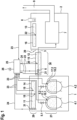
- FIG. 1 shows schematically several different embodiments of the invention, which can be applied individually or together.
- an installation room 1 which can be in particular a former tank room for an oil tank, for example in the basement of a building.
- One or more tanks 4.1, 4.2 for hydrogen are arranged in this installation room 1 (e.g. after a conversion of a former oil heating system). These are connected to a line 3 via tank valves 5.1, 5.2.
- a check valve 6 can close this line 3 . If hydrogen escapes from one of the tanks 4.1, 4.2 in the installation room 1, it essentially rises upwards, since hydrogen is lighter than air.
- a warning device 26 can be a warning display and/or an (optical or acoustic) warning signal or a message to a control center via a suitable communication channel.
- further safety measures can be initiated via control lines 24, for example closing tank valves 5.1, 5.2 or ventilating the installation room 1 by means of a fan 31.
- the sorbent 10.1, 10.2 contains certain amounts of hydrogen, as can occur in the event of a leak , binds and therefore cannot form an explosive mixture with the air in installation room 1. In this way, a leak is not only detected, but also controlled safely, at least for a certain period of time.
- sorbent 11 can also be placed in a first volume 14 in an upper area 28 of the Installation room 1 are arranged. This also allows the detection of leaks z. B. in lines or tank valves 5.1, 5.2 above the tanks 4.1, 4.2. Rising hydrogen is first adsorbed in the sorbent 11 on a surface of the volume 14 .
- An external temperature sensor 18 therefore responds more quickly and/or more strongly to a leak than an internal temperature sensor 19 which is arranged further away from the surface inside the first volume 14 .
- all the measures described can be initiated when a leak is detected.
- a former tank room for an oil tank can become a safe installation room for tanks 4.1, 4.2 for hydrogen. Since practically all escaping hydrogen is initially adsorbed, there is no risk of an explosive gas mixture forming in the installation room1.
- the sorbent 11 can be arranged so that it can be replaced or regenerated.
- the volume 14 can, for example, be completely exchangeable or have options for exchanging its contents. All types and forms of sorbent as described above are applicable.
- the same principle of leak detection can be used alternatively or additionally for other devices.
- a housing 2 with a heater 7 arranged therein e.g. B. a condensing boiler, which can be operated with hydrogen, are monitored for leaking hydrogen. Air typically enters the housing 2 somewhere through an air supply 8 and exhaust gases produced in the heater 7 are discharged via an exhaust system 9 . However, if hydrogen escapes somewhere, this in turn collects in an upper area 29 of the housing 2 .
- the temperature sensor 22 reports an increased temperature to the safety electronics 25, which in turn can then trigger one or more of the measures described above.
- the amount of hydrogen to be expected in the event of a leak in the housing 2 is very small and z. B. be limited quickly by closing the shut-off valve 6. This can be taken into account accordingly in the amounts of sorbent used.
- the risk of the formation of an explosive mixture is also greatly reduced.
- sorbent 12 can be arranged in a second volume 15 in such a way that it encloses the line 3 (or at least encompasses it in such a way that escaping and rising hydrogen gets into the sorbent 12).
- Leaks can in turn be detected by temperature increases at a first temperature sensor 20 and a second temperature sensor 21 . It is of particular advantage here to arrange two or more sensors 20, 21 along a line 3 in order to also obtain information about the location of a leak.
- temperature sensors require little maintenance and function stably over long periods of time.
- the here at The embodiments and advantages described in the individual applications can also be transferred in the same way to the other applications.
- the invention can be used individually for installation rooms 1, housing 2 or lines 3, ie also for housing 2 of heaters 7, which are supplied with fuel gas from a supply network.
- a combination as shown is possible and advantageous.
- the absorbent 11, 12, 13 can also be positioned at the illustrated locations without a monitoring functionality. Then the absorbent 11, 12, 13 "only" serves as a storage medium and possibly a transport medium for the hydrogen that has escaped.
- the present invention enables reliable and low-maintenance monitoring of devices that can be operated with hydrogen for leaks and at the same time reduces the risk of a leak occurring.
Landscapes
- Engineering & Computer Science (AREA)
- Physics & Mathematics (AREA)
- General Physics & Mathematics (AREA)
- Mechanical Engineering (AREA)
- General Engineering & Computer Science (AREA)
- Examining Or Testing Airtightness (AREA)
Applications Claiming Priority (1)
| Application Number | Priority Date | Filing Date | Title |
|---|---|---|---|
| DE102021118143.7A DE102021118143A1 (de) | 2021-07-14 | 2021-07-14 | Verfahren und Anordnung zur Erkennung einer Wasserstoffleckage, Computerprogrammprodukt sowie Verwendung eines Absorptionsmittels |
Publications (1)
| Publication Number | Publication Date |
|---|---|
| EP4137737A1 true EP4137737A1 (fr) | 2023-02-22 |
Family
ID=83115362
Family Applications (1)
| Application Number | Title | Priority Date | Filing Date |
|---|---|---|---|
| EP22184104.2A Pending EP4137737A1 (fr) | 2021-07-14 | 2022-07-11 | Procédé et dispositif de détection d'une fuite d'hydrogène, produit programme informatique, ainsi qu'utilisation d'un absorbant |
Country Status (2)
| Country | Link |
|---|---|
| EP (1) | EP4137737A1 (fr) |
| DE (1) | DE102021118143A1 (fr) |
Citations (5)
| Publication number | Priority date | Publication date | Assignee | Title |
|---|---|---|---|---|
| EP0994347A2 (fr) | 1998-10-16 | 2000-04-19 | VARTA Gerätebatterie GmbH | Capteur électrochimique de gaz |
| EP2098530B1 (fr) | 2008-03-05 | 2015-05-06 | Hanwha Chemical Corporation | Procédé de préparation de complexes hydrure de métal de transition organique et leur utilisation comme matériaux de stockage d'hydrogène |
| DE102016220992A1 (de) * | 2016-10-25 | 2018-04-26 | Bayerische Motoren Werke Aktiengesellschaft | Brennstoffführendes System mit mindestens einer Ausströmöffnung hinter einer Dichtstelle |
| EP2839046B1 (fr) | 2012-04-19 | 2019-10-02 | Ovonic Battery Company, Inc. | Alliages d'hydrure métallique ayant une activation améliorée et un taux d'efficacité élevé |
| CN111425720A (zh) * | 2020-04-30 | 2020-07-17 | 上海舜华新能源系统有限公司 | 一种加氢站无线智能巡检车 |
Family Cites Families (1)
| Publication number | Priority date | Publication date | Assignee | Title |
|---|---|---|---|---|
| EP1450097A3 (fr) | 2003-02-19 | 2007-12-12 | Taiyo Nippon Sanso Corporation | Dispositif d'alimentation en carburant et procédé de détection de fuites |
-
2021
- 2021-07-14 DE DE102021118143.7A patent/DE102021118143A1/de active Pending
-
2022
- 2022-07-11 EP EP22184104.2A patent/EP4137737A1/fr active Pending
Patent Citations (5)
| Publication number | Priority date | Publication date | Assignee | Title |
|---|---|---|---|---|
| EP0994347A2 (fr) | 1998-10-16 | 2000-04-19 | VARTA Gerätebatterie GmbH | Capteur électrochimique de gaz |
| EP2098530B1 (fr) | 2008-03-05 | 2015-05-06 | Hanwha Chemical Corporation | Procédé de préparation de complexes hydrure de métal de transition organique et leur utilisation comme matériaux de stockage d'hydrogène |
| EP2839046B1 (fr) | 2012-04-19 | 2019-10-02 | Ovonic Battery Company, Inc. | Alliages d'hydrure métallique ayant une activation améliorée et un taux d'efficacité élevé |
| DE102016220992A1 (de) * | 2016-10-25 | 2018-04-26 | Bayerische Motoren Werke Aktiengesellschaft | Brennstoffführendes System mit mindestens einer Ausströmöffnung hinter einer Dichtstelle |
| CN111425720A (zh) * | 2020-04-30 | 2020-07-17 | 上海舜华新能源系统有限公司 | 一种加氢站无线智能巡检车 |
Non-Patent Citations (1)
| Title |
|---|
| FOORGINEZHAD SAHAR ET AL: "Sensing advancement towards safety assessment of hydrogen fuel cell vehicles", JOURNAL OF POWER SOURCES, ELSEVIER, AMSTERDAM, NL, vol. 489, 21 January 2021 (2021-01-21), XP086495247, ISSN: 0378-7753, [retrieved on 20210121], DOI: 10.1016/J.JPOWSOUR.2021.229450 * |
Also Published As
| Publication number | Publication date |
|---|---|
| DE102021118143A1 (de) | 2023-01-19 |
Similar Documents
| Publication | Publication Date | Title |
|---|---|---|
| EP3368879B1 (fr) | Récipient d'échantillonnage et système d'échantillonnage ainsi que procédé de fonctionnement associé | |
| DE102021118862A1 (de) | Schutzvorrichtung für Energiespeicher | |
| EP3748257B1 (fr) | Dispositif pour la performance sûre d'un procédé circulaire thermodynamique à rotation à gauche au moyen d'un fluide de travail inflammable avec adsorption de fluide | |
| EP3705823B1 (fr) | Dispositif pour une intervention de service en toute sécurité pour un boîtier et procédé d'ouverture du boîtier. | |
| EP3581861A2 (fr) | Sorption du fluide | |
| DE2856349B2 (de) | Atemschutzgerät mit sauerstoffabgebender Chemikalpatrone | |
| DE102018133203A1 (de) | Spülsystem und Verfahren zu dessen Überwachung | |
| EP3693078A1 (fr) | Capteur de niveau de remplissage | |
| EP4137737A1 (fr) | Procédé et dispositif de détection d'une fuite d'hydrogène, produit programme informatique, ainsi qu'utilisation d'un absorbant | |
| EP4040064B1 (fr) | Utilisation pour détection des fuites de réfrigérant dans un circuit réfrigérant agencé dans un boîtier fermé | |
| DE2950198A1 (de) | Einrichtung und verfahren zur lagerung von verbrauchten brennelementen | |
| DE102019114738A1 (de) | Fluidadsorption | |
| EP3280912B1 (fr) | Éolienne à circuit de liquide et composants associés | |
| DE102014226198A1 (de) | Latentwärmespeicher | |
| EP0211160B1 (fr) | Méthode et dispositif de mise en évidence du dégagement d'un gaz | |
| DE102007021875A1 (de) | Behältersystem mit einer Vakuum-Isolationshülle | |
| DE102019006343A1 (de) | Messkammer und Messstand | |
| DE1625933A1 (de) | Vorrichtung zum Feststellen von Daempfen od.dgl. | |
| DE202010016522U1 (de) | Vorrichtung zur Adsorptionsbehandlung eines Fluids oder Fluidstroms | |
| AT230285B (de) | Einrichtung zur Verminderung von Korrosionsschäden sowie zur Anzeige von Undichtheiten an doppelwandigen Lagerbehältern | |
| DE3036515C2 (de) | Verfahren und Vorrichtung zur kontrollierten Be- und Entlüftung unterirdischer Hohlräume | |
| DE102005040108B3 (de) | Vorrichtung zur Ableitung von im Fall eines Quench eines supraleitenden Magneten entstehenden Gases | |
| JPS6060342A (ja) | 油圧防振器のオイル補充装置 | |
| DE2541664C3 (de) | Leckschutzeinrichtung | |
| McCormack et al. | REMOVAL OF AIRBORNE FISSION PRODUCTS BY RECIRCULATING FILTER SYSTEMS IN THE CONTAINMENT SYSTEMS EXPERIMENT. |
Legal Events
| Date | Code | Title | Description |
|---|---|---|---|
| PUAI | Public reference made under article 153(3) epc to a published international application that has entered the european phase |
Free format text: ORIGINAL CODE: 0009012 |
|
| STAA | Information on the status of an ep patent application or granted ep patent |
Free format text: STATUS: THE APPLICATION HAS BEEN PUBLISHED |
|
| AK | Designated contracting states |
Kind code of ref document: A1 Designated state(s): AL AT BE BG CH CY CZ DE DK EE ES FI FR GB GR HR HU IE IS IT LI LT LU LV MC MK MT NL NO PL PT RO RS SE SI SK SM TR |
|
| STAA | Information on the status of an ep patent application or granted ep patent |
Free format text: STATUS: REQUEST FOR EXAMINATION WAS MADE |
|
| 17P | Request for examination filed |
Effective date: 20230815 |
|
| RBV | Designated contracting states (corrected) |
Designated state(s): AL AT BE BG CH CY CZ DE DK EE ES FI FR GB GR HR HU IE IS IT LI LT LU LV MC MK MT NL NO PL PT RO RS SE SI SK SM TR |