EP4137741B1 - Bougie photosensible - Google Patents
Bougie photosensible Download PDFInfo
- Publication number
- EP4137741B1 EP4137741B1 EP21207464.5A EP21207464A EP4137741B1 EP 4137741 B1 EP4137741 B1 EP 4137741B1 EP 21207464 A EP21207464 A EP 21207464A EP 4137741 B1 EP4137741 B1 EP 4137741B1
- Authority
- EP
- European Patent Office
- Prior art keywords
- candle
- light
- shell
- emitting device
- container
- Prior art date
- Legal status (The legal status is an assumption and is not a legal conclusion. Google has not performed a legal analysis and makes no representation as to the accuracy of the status listed.)
- Active
Links
Images


Classifications
-
- F—MECHANICAL ENGINEERING; LIGHTING; HEATING; WEAPONS; BLASTING
- F21—LIGHTING
- F21S—NON-PORTABLE LIGHTING DEVICES; SYSTEMS THEREOF; VEHICLE LIGHTING DEVICES SPECIALLY ADAPTED FOR VEHICLE EXTERIORS
- F21S6/00—Lighting devices intended to be free-standing
- F21S6/001—Lighting devices intended to be free-standing candle-shaped
-
- F—MECHANICAL ENGINEERING; LIGHTING; HEATING; WEAPONS; BLASTING
- F21—LIGHTING
- F21S—NON-PORTABLE LIGHTING DEVICES; SYSTEMS THEREOF; VEHICLE LIGHTING DEVICES SPECIALLY ADAPTED FOR VEHICLE EXTERIORS
- F21S19/00—Lighting devices or systems employing combinations of electric and non-electric light sources; Replacing or exchanging electric light sources with non-electric light sources or vice versa
-
- C—CHEMISTRY; METALLURGY
- C11—ANIMAL OR VEGETABLE OILS, FATS, FATTY SUBSTANCES OR WAXES; FATTY ACIDS THEREFROM; DETERGENTS; CANDLES
- C11C—FATTY ACIDS FROM FATS, OILS OR WAXES; CANDLES; FATS, OILS OR FATTY ACIDS BY CHEMICAL MODIFICATION OF FATS, OILS, OR FATTY ACIDS OBTAINED THEREFROM
- C11C5/00—Candles
- C11C5/006—Candles wicks, related accessories
-
- C—CHEMISTRY; METALLURGY
- C11—ANIMAL OR VEGETABLE OILS, FATS, FATTY SUBSTANCES OR WAXES; FATTY ACIDS THEREFROM; DETERGENTS; CANDLES
- C11C—FATTY ACIDS FROM FATS, OILS OR WAXES; CANDLES; FATS, OILS OR FATTY ACIDS BY CHEMICAL MODIFICATION OF FATS, OILS, OR FATTY ACIDS OBTAINED THEREFROM
- C11C5/00—Candles
- C11C5/008—Candles characterised by their form; Composite candles, e.g. candles containing zones of different composition, inclusions, or the like
-
- F—MECHANICAL ENGINEERING; LIGHTING; HEATING; WEAPONS; BLASTING
- F21—LIGHTING
- F21S—NON-PORTABLE LIGHTING DEVICES; SYSTEMS THEREOF; VEHICLE LIGHTING DEVICES SPECIALLY ADAPTED FOR VEHICLE EXTERIORS
- F21S10/00—Lighting devices or systems producing a varying lighting effect
- F21S10/04—Lighting devices or systems producing a varying lighting effect simulating flames
- F21S10/043—Lighting devices or systems producing a varying lighting effect simulating flames by selectively switching fixed light sources
-
- F—MECHANICAL ENGINEERING; LIGHTING; HEATING; WEAPONS; BLASTING
- F21—LIGHTING
- F21V—FUNCTIONAL FEATURES OR DETAILS OF LIGHTING DEVICES OR SYSTEMS THEREOF; STRUCTURAL COMBINATIONS OF LIGHTING DEVICES WITH OTHER ARTICLES, NOT OTHERWISE PROVIDED FOR
- F21V19/00—Fastening of light sources or lamp holders
- F21V19/04—Fastening of light sources or lamp holders with provision for changing light source, e.g. turret
-
- F—MECHANICAL ENGINEERING; LIGHTING; HEATING; WEAPONS; BLASTING
- F21—LIGHTING
- F21V—FUNCTIONAL FEATURES OR DETAILS OF LIGHTING DEVICES OR SYSTEMS THEREOF; STRUCTURAL COMBINATIONS OF LIGHTING DEVICES WITH OTHER ARTICLES, NOT OTHERWISE PROVIDED FOR
- F21V23/00—Arrangement of electric circuit elements in or on lighting devices
- F21V23/04—Arrangement of electric circuit elements in or on lighting devices the elements being switches
- F21V23/0442—Arrangement of electric circuit elements in or on lighting devices the elements being switches activated by means of a sensor, e.g. motion or photodetectors
- F21V23/0457—Arrangement of electric circuit elements in or on lighting devices the elements being switches activated by means of a sensor, e.g. motion or photodetectors the sensor sensing the operating status of the lighting device, e.g. to detect failure of a light source or to provide feedback to the device
-
- F—MECHANICAL ENGINEERING; LIGHTING; HEATING; WEAPONS; BLASTING
- F21—LIGHTING
- F21V—FUNCTIONAL FEATURES OR DETAILS OF LIGHTING DEVICES OR SYSTEMS THEREOF; STRUCTURAL COMBINATIONS OF LIGHTING DEVICES WITH OTHER ARTICLES, NOT OTHERWISE PROVIDED FOR
- F21V35/00—Candle holders
-
- G—PHYSICS
- G02—OPTICS
- G02B—OPTICAL ELEMENTS, SYSTEMS OR APPARATUS
- G02B6/00—Light guides; Structural details of arrangements comprising light guides and other optical elements, e.g. couplings
- G02B6/0001—Light guides; Structural details of arrangements comprising light guides and other optical elements, e.g. couplings specially adapted for lighting devices or systems
- G02B6/0005—Light guides; Structural details of arrangements comprising light guides and other optical elements, e.g. couplings specially adapted for lighting devices or systems the light guides being of the fibre type
- G02B6/0006—Coupling light into the fibre
-
- G—PHYSICS
- G02—OPTICS
- G02B—OPTICAL ELEMENTS, SYSTEMS OR APPARATUS
- G02B6/00—Light guides; Structural details of arrangements comprising light guides and other optical elements, e.g. couplings
- G02B6/0001—Light guides; Structural details of arrangements comprising light guides and other optical elements, e.g. couplings specially adapted for lighting devices or systems
- G02B6/0011—Light guides; Structural details of arrangements comprising light guides and other optical elements, e.g. couplings specially adapted for lighting devices or systems the light guides being planar or of plate-like form
- G02B6/0081—Mechanical or electrical aspects of the light guide and light source in the lighting device peculiar to the adaptation to planar light guides, e.g. concerning packaging
- G02B6/0095—Light guides as housings, housing portions, shelves, doors, tiles, windows, or the like
-
- H—ELECTRICITY
- H05—ELECTRIC TECHNIQUES NOT OTHERWISE PROVIDED FOR
- H05B—ELECTRIC HEATING; ELECTRIC LIGHT SOURCES NOT OTHERWISE PROVIDED FOR; CIRCUIT ARRANGEMENTS FOR ELECTRIC LIGHT SOURCES, IN GENERAL
- H05B47/00—Circuit arrangements for operating light sources in general, i.e. where the type of light source is not relevant
- H05B47/10—Controlling the light source
- H05B47/105—Controlling the light source in response to determined parameters
- H05B47/11—Controlling the light source in response to determined parameters by determining the brightness or colour temperature of ambient light
-
- F—MECHANICAL ENGINEERING; LIGHTING; HEATING; WEAPONS; BLASTING
- F21—LIGHTING
- F21V—FUNCTIONAL FEATURES OR DETAILS OF LIGHTING DEVICES OR SYSTEMS THEREOF; STRUCTURAL COMBINATIONS OF LIGHTING DEVICES WITH OTHER ARTICLES, NOT OTHERWISE PROVIDED FOR
- F21V2200/00—Use of light guides, e.g. fibre optic devices, in lighting devices or systems
- F21V2200/10—Use of light guides, e.g. fibre optic devices, in lighting devices or systems of light guides of the optical fibres type
- F21V2200/13—Use of light guides, e.g. fibre optic devices, in lighting devices or systems of light guides of the optical fibres type the light being emitted at the end of the guide
-
- F—MECHANICAL ENGINEERING; LIGHTING; HEATING; WEAPONS; BLASTING
- F21—LIGHTING
- F21W—INDEXING SCHEME ASSOCIATED WITH SUBCLASSES F21K, F21L, F21S and F21V, RELATING TO USES OR APPLICATIONS OF LIGHTING DEVICES OR SYSTEMS
- F21W2121/00—Use or application of lighting devices or systems for decorative purposes, not provided for in codes F21W2102/00 – F21W2107/00
-
- F—MECHANICAL ENGINEERING; LIGHTING; HEATING; WEAPONS; BLASTING
- F21—LIGHTING
- F21Y—INDEXING SCHEME ASSOCIATED WITH SUBCLASSES F21K, F21L, F21S and F21V, RELATING TO THE FORM OR THE KIND OF THE LIGHT SOURCES OR OF THE COLOUR OF THE LIGHT EMITTED
- F21Y2103/00—Elongate light sources, e.g. fluorescent tubes
- F21Y2103/30—Elongate light sources, e.g. fluorescent tubes curved
-
- F—MECHANICAL ENGINEERING; LIGHTING; HEATING; WEAPONS; BLASTING
- F21—LIGHTING
- F21Y—INDEXING SCHEME ASSOCIATED WITH SUBCLASSES F21K, F21L, F21S and F21V, RELATING TO THE FORM OR THE KIND OF THE LIGHT SOURCES OR OF THE COLOUR OF THE LIGHT EMITTED
- F21Y2115/00—Light-generating elements of semiconductor light sources
- F21Y2115/10—Light-emitting diodes [LED]
Definitions
- This invention relates to a candle, and in particular to a photosensitive candle with a candle, a light-emitting device and a lighting control component which controls illumination of the light-emitting device when the candle is lit.
- wax candles are no longer a main source of illumination in modern society.
- wax candles are still widely used as decorations in many occasions such as art performances, family parties and wine bars to create a pleasant environment.
- WO 2014/184217 A1 discloses an illuminated candle according to the preamble of claim 1, in particular comprising:- a container; - an illuminating module positioned in the bottom part of the container and comprising at least one light-emitting diode (LED) controlled by an electronic circuit to which a light sensor is connected; and - a burning insert positioned on top of the illuminating module and having embedded a wick and an optical fiber, the optical fiber being optically coupled with the light sensor.
- LED light-emitting diode
- US 2006/177786 A1 discloses a luminescent wax candle container comprising: a container body having an opening and made of transparent or semi-transparent materials; a wax candle having a top surface and fully or partially filled in said container body; a wick placed in said wax candle and sticking out the top surface of said wax candle; a luminescent module placed at the bottom of said wax candle and including a power source, a control module connected to said power source, a photosensitive circuit including a photosensitive component with a photosensitive surface and one or more LEDs, in which said control module controls luminescence of said LEDs in response to signals from said photosensitive circuit; and a light-guide fiber placed along with said wick, wherein one end of said light-guide fiber is close to the part of said wick sticking out the top surface of said wax candle and the other end touches the photosensitive surface of the photosensitive component in said photosensitive.
- US 2007/003894 A1 discloses an electronic candle comprising: a candle body, said candle body comprising a center stick of wax and a perfume stick surrounding said center stick of wax, said center stick of wax having a wick, said perfume stick being formed of a mixture containing a wax and a perfume; an electronic device fastened to a bottom side of said perfume stick, said electronic device comprising a circuit board adapted to produce sound and lighting effects, and a photo sensor adapted to control the operation of said circuit board; and at least one optical fiber embedded in said center stick and adapted to transmit light from the flame burning at said wick of said center stick to said photo sensor to induce said photo sensor.
- CN 211 170 633 U discloses a light-controlled combustible candle is characterized in that it comprises: a cup body, the cup body includes an inner cup and a mounting box, the mounting box is located at the bottom of the inner cup; the combustible component includes a wick, a combustible optical fiber and wax, the wick and the combustible optical fiber are arranged side by side in the inner cup, the lower end of the wick and the combustible optical fiber extend to the upper end of the mounting box, the wick The upper end of the flammable optical fiber extends out of the inner cup, the upper end of the combustible optical fiber is located in the inner cup, the wax is filled in the inner cup, and the wax wraps the wick, combustible optical fiber and the inner cup in the inner cup.
- the electronic component includes a controller, a light sensor and a light string
- the controller is located in the mounting box
- the light sensor is mounted on the controller
- the photosensitive end of the light sensor penetrates
- the upper end of the mounting box is connected to the lower end of the combustible optical fiber
- the light string is located outside the inner cup
- one end of the light string penetrates into the inner cup and extends to the controller connection.
- the sensor is used to obtain the light signal from the combustible optical fiber and produce an electric signal
- the controller is used to control the lighting of the light string according to the electric signal generated by the light sensor.
- US 4 477 249 A discloses a sound-emitting flame-producing device, comprising a body of combustible material which is liquid at least when heated to a predetermined temperature; elongated wick means extending through said body and having two ends one of which extends out of said body and is permeated by a quantity of the combustible material which reacts with ambient oxygen and is replenished from said body when lit with attendant production of a flame that emits a plurality of radiation components of different wavelengths; sound-generating means disposed at a location which is remote from said one end of said wick means and operative for generating a succession of audible sounds when activated; and means for activating said sound-generating means upon exposure to at least one of said flame radiation components.
- the invention is a photosensitive candle as defined in claim 1.
- a photosensitive candle comprising: (a) a candle container comprising a candle container base and a candle container opening opposite the candle container base; (b) an inner container housed within the candle container, comprising an inner container base and an inner container opening opposite the inner container base; (c) a candle component disposed in the inner container, comprising: a candle body filled within the inner container, having a top surface proximate to or substantially aligned with the inner container opening; a wick with an exposed portion protruding out of the top surface of the candle body; and an optical fiber embedded in the candle body and positioned juxtapose to the wick for transmitting flame lights of the wick, wherein the optical fiber comprises a first end proximate to the exposed portion of the wick and an opposing second end; (d) a lighting control component disposed in the candle container, comprising: a casing attached to the candle container base and positioned below the inner container base, comprising an interior cavity; a controller disposed
- a photosensitive candle comprising: (a) a shell component including: an outer-shell comprising an outer-shell base; an inner-shell comprising an inner-shell base, wherein the inner-shell is housed within the outer-shell with the inner-shell base disposed on top of the outer-shell base; a filling that fills in a space between the inner-shell and the outer-shell; (b) a candle container comprising a candle container base and a candle container opening opposite the candle container base, wherein the candle container is configured to be removably accommodated within the inner-shell with the candle container base disposed on top of the inner-shell base; (c) an inner container housed within the candle container, comprising an inner container base and an inner container opening opposite the inner container base; (d) a candle component disposed in the inner container, comprising: a candle body filled within the inner container, having a top surface proximate to or substantially aligned with the inner container opening; a wick with an exposed portion protruding
- the photosensitive candle comprises a combustible candle component comprising a wick and an optical fiber, a light-emitting device and a light control component.
- a flame light of the wick can be transmitted by the optical fiber to the light sensor to generate light signals, which in turn are passed to the controller of the light control component to control the light-emitting device based on the intensity of the received light signals.
- the light-emitting device can be switched on/off, change its luminescence and/or change its light pattern in response to the fluctuation of the flame light of the wick without the need of any manual operation, thereby combining the visual effect of a natural candle flame with the dynamic illumination of the light-emitting device to provide a unique aesthetic experience.
- the light-emitting device will be switched off automatically when the wick flame is extinguished, the power of the battery in the photosensitive candle can be saved.
- the candle component is housed in an inner container and separated from the casing of the lighting control component, thereby preventing the wick flame and/or the molten wax of the candle component from reaching the casing and heating the electronic components housed within the casing. This avoids over-heating the light control component and causing smoke or even fire hazards, thereby improving the safety when using the photosensitive candle.
- the controller is configured to control the light-emitting device such that when the candle component is lit, a higher intensity of light is required to switch on the light-emitting device, whereas when the candle component is burning normally, the light-emitting device will be switched off only when the intensity of light reduces to a lower value, thereby avoiding the constant switching on/off of the light-emitting device and maintaining the stability of the illumination of the light-emitting device during use.
- the light-emitting device may be switched from an ON state to an OFF state only if the intensity of the light signals is lesser than a predetermined lower threshold for a predetermined period of time, thereby avoiding undesirable switching off of the light-emitting device when the flame light of the wick are temporarily diminished (but not extinguished) by a disturbance of airflow around the photosensitive candle. As such, the light-emitting device can illuminate stably and continuously.
- the candle container is removable from the inner-shell of the shell component. As such, it is convenient to replace the candle container after the candle component is used up while the shell component is reusable for a long period of time, thereby offering a cost-effective and environmental friendlier solution for using the photosensitive candle.
- the removable candle containers with different designs/color can mix and match with different types of shell components, thereby offering a wide variety of combinations according to the user's preference.
- the interior cavity of the casing is accessible by a user, therefore the power source (e.g. batteries) of the light control component can be replaced without the need to dispose the entire photosensitive candle after use, making it more environmental friendly to use.
- the power source e.g. batteries
- Couple or “connect” refers to electrical coupling or connection either directly or indirectly via one or more electrical means unless otherwise stated.
- the terms "general” or “generally”, or “substantial” or “substantially” mean that the recited characteristic, angle, shape, state, structure, or value need not be achieved exactly, but that deviations or variations, including for example, tolerances, measurement error, measurement accuracy limitations and other factors known to those of skill in the art, may occur in amounts that do not preclude the effect the characteristic was intended to provide.
- an object that has a "generally” rectangular shape would mean that the object has either an exact rectangular shape or a nearly exact rectangular shape.
- an object that is "substantially” perpendicular to a surface would mean that the object is either exactly perpendicular to the surface or nearly exactly perpendicular to the surface, e.g., has a 5% deviation.
- attach refers to direct or indirect physical joining one component to another.
- the term "light-emitting device” refers to any device that is configured to emit light or having a light-emitting element or the like, including but not limited to a light emitting diode (LED), a light strip, a light bulb, a light ring, a light block, a light string and a light tube.
- LED light emitting diode
- ON state refers to a state of the at least one light-emitting device in which the light-emitting device is turned on and lights up.
- OFF state refers to a state of the at least one light-emitting device in which the light-emitting device is turned off and does not light up.
- light signal refers to signal generated by a light sensor in response to light emitted from a light source.
- light signals associated with a flame light of the wick refers to light signals generated by a light sensor in response to light created by burning of a wick of a candle component.
- illumination refers to the luminescence or light pattern of a light source.
- illumination of the at least one light-emitting device refers to the luminescence (e.g. brightness, light output, color temperature, etc.) or light pattern (e.g. light mode, change of color, frequency of flashing the light, etc.) of the light-emitting device.
- the term "transparent" means at least partially optically clear and having the property of allowing certain amount of light rays transmitting through its substance. The amount of light rays that is transmissible can be determined according to the user's application.
- ignition temperature refers to the lowest temperature at which a substance catches fire.
- a photosensitive candle comprising: (a) a candle container comprising an opening; (b) a candle component disposed in the candle container, comprising: a candle body having a surface proximate to or substantially aligned with the opening; a wick with an exposed portion protruding out of the surface of the candle body; and an optical fiber embedded in the candle body and positioned juxtapose to the wick for transmitting flame lights of the wick, wherein the optical fiber comprises a first end proximate to the exposed portion of the wick and an opposing second end; (c) a lighting control component disposed in the candle container, comprising: a casing comprising an interior cavity; a controller and a power source disposed within the interior cavity; and a light sensor connected to the controller, comprising a photosensitive element proximate to the second end of the optical fiber to detect light transmitted therefrom; and (d) at least one light-emitting device connected to the controller.
- the controller is configured to: (i) receive light signals associated with the flame lights of the wick from the light sensor; (ii) switch the at least one light-emitting device from an OFF state to an ON state if an intensity of the light signals is greater than a predetermined upper threshold; (iii)maintain the at least one light-emitting device in the ON state if the at least one light-emitting device is in the ON state and the intensity of the light signals is greater than a predetermined lower threshold; (iv) switch the at least one light-emitting device from the ON state to the OFF state if the intensity of the light signals is lesser than the predetermined lower threshold for a predetermined period of time; and (v) maintain the at least one light-emitting device in the OFF state if the at least one light-emitting device is in the OFF state and the intensity of the light signals is lesser than the predetermined upper threshold.
- the lighting control component further comprises an analog-digital converting module connected to the controller, wherein the analog-digital converting module is configured to (i) analyze and process the light signals to generate digital signals, wherein the digital signals represent the intensity of the light signals, and (ii) transmit the digital signals to the controller, wherein the controller is further configured to control an illumination of the at least one light-emitting device based on the digital signals received from the analog-digital converting module when the at least one light-emitting device is in the ON state.
- the analog-digital converting module is configured to (i) analyze and process the light signals to generate digital signals, wherein the digital signals represent the intensity of the light signals, and (ii) transmit the digital signals to the controller, wherein the controller is further configured to control an illumination of the at least one light-emitting device based on the digital signals received from the analog-digital converting module when the at least one light-emitting device is in the ON state.
- the lighting control component further comprises a memory that stores a preset program
- the controller is further configured to control an illumination of the at least one light-emitting device based on the preset program when the at least one light-emitting device is in the ON state.
- the predetermined period of time is between 1 seconds to 6 seconds.
- the candle container further comprises a candle container base opposite the opening
- the photosensitive candle further comprises a shell component including: an outer-shell comprising an outer-shell base, wherein the outer-shell is configured to accommodate the candle container with the candle container base disposed on top of the outer-shell base; and a filling that fills in a space between the candle container and the outer-shell.
- the at least one light-emitting device comprises a main body extending out of the casing and the candle container and is at least partially embedded in the filling.
- the photosensitive candle further comprises an outer-shell hole formed on the outer-shell base; a candle container hole formed on the candle container base; a casing hole formed on the casing; and a removable cover for covering the outer-shell hole.
- the outer-shell hole, the candle container hole and the casing hole are substantially aligned with each other such that the interior cavity of the casing is accessible by a user when the removable cover is opened.
- the candle container further comprises a candle container base opposite the opening
- the photosensitive candle further comprises a shell component including: an outer-shell comprising an outer-shell base; an inner-shell comprising an inner-shell base, wherein the inner-shell is housed within the outer-shell with the inner-shell base disposed on top of the outer-shell base, and the inner-shell is configured to removably accommodate the candle container with the candle container base disposed on top of the inner-shell base; and a filling that fills in a space between the inner-shell and the outer-shell.
- the at least one light-emitting device comprises a main body extending out of the casing, the candle container and the inner-shell and is partially embedded in the filling.
- the photosensitive candle further comprises a candle container hole formed on the candle container base; a casing hole formed on the casing; and a removable cover for covering the candle container hole.
- the candle container hole and the casing hole are substantially aligned with each other, such that the interior cavity of the casing is accessible by a user when the candle container is removed from the inner-shell and the removable cover is opened.
- the photosensitive candle further comprises an inner container housed within the candle container, comprising an inner container base positioned above the casing of the lighting control component, wherein the candle component is disposed within the inner container; a light guiding channel attached to a defined area of the inner container base, comprising: a first portion disposed within the inner container, configured to accommodate a part of the wick and the second end of the optical fiber; and a second portion disposed outside the inner container and extending away from the inner container base, configured to accommodate at least a part of the photosensitive element of the light sensor.
- the second end of the optical fiber and the photosensitive element are separated from each other by the defined area of the inner container base, and the defined area is made of substantially transparent material, and the first portion and the second portion are substantially aligned with each other, such that the light transmitted from the optical fiber are detectable by the photosensitive element.
- the at least one light-emitting device comprises at least two light strings with different colors.
- a photosensitive candle comprising: (a) a candle container comprising a candle container base and a candle container opening opposite the candle container base; (b) an inner container housed within the candle container, comprising an inner container base and an inner container opening opposite the inner container base; (c) a candle component disposed in the inner container, comprising: a candle body filled within the inner container, having a top surface proximate to or substantially aligned with the inner container opening; a wick with an exposed portion protruding out of the top surface of the candle body; and an optical fiber embedded in the candle body and positioned juxtapose to the wick for transmitting flame lights of the wick, wherein the optical fiber comprises a first end proximate to the exposed portion of the wick and an opposing second end; (d) a lighting control component disposed in the candle container, comprising: a casing attached to the candle container base and positioned below the inner container base, comprising an interior cavity; a controller disposed
- the controller is further configured to: (i) switch the at least one light-emitting device from an OFF state to an ON state if an intensity of the light signals is greater than a predetermined upper threshold; (ii) once the at least one light-emitting device is switched to the ON state, maintain the at least one light-emitting device in the ON state if the intensity of the light signals is greater than a predetermined lower threshold; (iii) if the intensity of the light signals becomes lesser than the predetermined lower threshold when the at least one light-emitting device is in the ON state, start a timer to measure a length of time in which the intensity of the light signals is lesser than the predetermined lower threshold; and if the length of time is shorter than a predetermined period of time, maintain the at least one light-emitting device in the ON state; if the length of time is longer than the predetermined period of time, switch the at least one light-emitting device from the ON state to the OFF state; and (i) switch the at least one light-emit
- the photosensitive candle further comprises a shell component including: an outer-shell comprising an outer-shell base, wherein the outer-shell is configured to accommodate the candle container with the candle container base disposed on top of the outer-shell base; and a filling that fills in a space between the candle container and the outer-shell, wherein the main body of the at least one light-emitting device is at least partially embedded in the filling.
- a shell component including: an outer-shell comprising an outer-shell base, wherein the outer-shell is configured to accommodate the candle container with the candle container base disposed on top of the outer-shell base; and a filling that fills in a space between the candle container and the outer-shell, wherein the main body of the at least one light-emitting device is at least partially embedded in the filling.
- the photosensitive candle further comprises a shell component including: an outer-shell comprising an outer-shell base; an inner-shell comprising an inner-shell base, wherein the inner-shell is housed within the outer-shell with the inner-shell base disposed on top of the outer-shell base, and the inner-shell is configured to removably accommodate the candle container with the candle container base disposed on top of the inner-shell base; and a filling that fills in a space between the inner-shell and the outer-shell, wherein the at least one light-emitting device comprising a main body extending out of the casing, the candle container and the inner-shell and is at least partially embedded in the filling.
- a shell component including: an outer-shell comprising an outer-shell base; an inner-shell comprising an inner-shell base, wherein the inner-shell is housed within the outer-shell with the inner-shell base disposed on top of the outer-shell base, and the inner-shell is configured to removably accommodate the candle container with the candle container base disposed on
- At least one light-emitting device comprises a connecting end and a main body, wherein the connecting end is connected to the controller and the main body extends out of the casing.
- the controller is further configured to perform the following steps: if the intensity of the light signals becomes lesser than the predetermined lower threshold when the at least one light-emitting device is in the ON state, start a timer to measure a length of time in which the intensity of the light signals is lesser than the predetermined lower threshold; and if the length of time is shorter than a predetermined period of time, maintain the at least one light-emitting device in the ON state; if the length of time is longer than the predetermined period of time, switch the at least one light-emitting device from the ON state to the OFF state.
- the lighting control component further comprises an analog-digital converting module connected to the controller, wherein the analog-digital converting module is configured to (i) analyze and process the light signals to generate digital signals, wherein the digital signals represent the intensity of the light signals, and (ii) transmit the digital signals to the controller, wherein the controller is further configured to control an illumination of the at least one light-emitting device based on the digital signals received from the analog-digital converting module when the at least one light-emitting device is in the ON state.
- the lighting control component further comprises a memory that stores a preset program
- the controller is further configured to control an illumination of the at least one light-emitting device based on the preset program when the at least one light-emitting device is in the ON state.
- the photosensitive candle further comprises a candle container hole formed on the candle container base; a casing hole formed on the casing; and a removable cover for covering the candle container hole.
- the candle container hole and the casing hole are substantially aligned with each other, such that the interior cavity of the casing is accessible by a user when the candle container is removed from the inner-shell and the removable cover is opened.
- the at least one light-emitting device comprises at least two light strings with different colors.
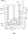
- FIG. 1A shows the photosensitive candle 1000A including a shell component 1100, a candle container 1200, an inner container 1300, a candle component 1400, a lighting control component 1500, a light-emitting device 1600 and a light guiding channel 1800.
- the shell component 1100 includes an outer-shell 1110 for accommodating the candle container 1200, and a filling 1120 disposed between the candle container 1200 and the outer-shell 1110.
- the outer-shell 1110 is shaped as a cup with a substantially-flat outer-shell base 1112 and an outer-shell opening 1111 opposite the outer-shell base 1112, defining a height of the outer-shell 1110 therebetween.
- the direction towards the outer-shell opening 1111 is called top and the direction towards the outer-shell base 1112 is called bottom.
- the outer-shell 1110 can be made of a substantially transparent material or semi-transparent material to allow for a certain degree of light transmission, including but not limited to glass, crystal, plastic made of Polyethylene Terephthalate (PET), Polyvinyl Chloride (PVC), Polypropylene (PP), Polystyrene (PS), Polycarbonate (PC), Polymethyl Methacrylate (PMMA), Polyamide, ABS & SAN, Polyethylene, High Density Polyethylene (HDPE), Low Density Polyethylene (LDPE), TPU or a combination thereof.
- the outer-shell 1110 may be painted, printed or carved with various patterns on its outer surface for decorative purposes.
- the outer-shell 1110 has a larger diameter than the candle container 1200 such that a space exists between the candle container 1200 and the outer-shell 1110. In some embodiments, the space is sufficiently large to accommodate at least part of the light-emitting device 1600.
- the filling 1120 at least partially fills in the space between the candle container 1200 and the outer-shell 1110, thereby embedding at least part of the light-emitting device 1600 therewithin.
- the filling 1120 has a filling surface 1123 that is arranged at a level lower than the outer-shell opening 1111.
- the filling 1120 can be made of a substantially transparent material or semi-transparent material to allow for a certain degree of light transmission, including but not limited to gel wax, paraffin wax, crystal wax, transparent or semi-transparent polymer made of Polyethylene Terephthalate (PET), Polyethylene terephthalate -1, 4 - cyclohexane 2 methyl ester (PETG), Polyvinyl Chloride (PVC), Polyethylene (PE), Polypropylene (PP), Polystyrene (PS), Polycarbonate (PC), Polymethyl Methacrylate (PMMA), Polyamide, ABS & SAN, Polyethylene, High Density Polyethylene (HDPE), Low Density Polyethylene (LDPE), TPU, liquid silicone rubber, cyclic olefin copolymers, ionomer resin, fluorinated ethylene propylene (FEP), styrene methyl methacrylate (SMMA), epoxy or a combination thereof.
- PET Polyethylene Terephthalate
- PET Polyethylene ter
- the shell component 1100 may further include a plurality of decorative pieces 1122 that is embedded and randomly dispersed within the filling 1120.
- the decorative pieces 1122 can come in a variety of shapes and sizes.
- the plurality of decorative pieces 1122 may include materials that can reflect and/or refract light, such as crystals, metal pieces, plastics or a combination thereof, such that a richer and more colorful visual effect can be produced when the light-emitting device illuminates.
- the shell component 1100 may not include any decorative material.
- the candle container 1200 is shaped as a cup with an interior space 1203, a substantially-flat candle container base 1202 and a candle container opening 1201 opposite the candle container base 1202, defining a height of the candle container 1200 therebetween.
- the candle container 1200 is disposed within the outer-shell 1110 with the candle container base 1202 placed on top of the upper surface of the outer-shell base 1112.
- the candle container 1200 may be fixedly housed within the outer-shell 1110.
- the height of the candle container 1200 is lesser than the height of the outer-shell 1110, and the candle container opening 1201 is arranged at a level lower than the outer-shell opening 1111 but higher than the filling surface 1123.
- the inner container 1300, the lighting control component 1500 and the light guiding channel 1800 are disposed within interior space 1203 of the candle container 1200.
- the inner container 1300 is shaped as a cup with a substantially-flat inner container base 1302 and an inner container opening 1301 opposite the inner container base 1302, defining a height of the inner container 1300 therebetween.
- the inner container 1300 has a diameter slightly smaller than the candle container 1200 such that the inner container 1300 can be housed within the candle container 1200.
- the height of the inner container 1300 is lesser than the height of the candle container 1200.
- the inner container 1300 has a central axis (shown as dotted line 1311 in Fig.
- the inner container 1300 is positioned above the lighting control component 1500 within the candle container 1200, and the inner container opening 1301 is arranged at a level that is substantially aligned with the candle container opening 1201.
- the candle container 1200 and the inner container 1300 can be made of heat-resistant or flame-retardant materials, including but not limited to glass, heat-resistant plastic such as Polyetherimide (PEI), Polyether ether ketone (PEEK), Polytetrafluoroethylene (PTFE), Polybenzimidazole (PBI), Polydicyclopentadiene (pDCPD), flame resistant plastics and flame retardant plastics.
- heat-resistant plastic such as Polyetherimide (PEI), Polyether ether ketone (PEEK), Polytetrafluoroethylene (PTFE), Polybenzimidazole (PBI), Polydicyclopentadiene (pDCPD), flame resistant plastics and flame retardant plastics.
- PEI Polyetherimide
- PEEK Polyether ether ketone
- PTFE Polytetrafluoroethylene
- PBI Polybenzimidazole
- pDCPD Polydicyclopentadiene
- Fig. 1A also shows the candle component 1400 disposed in the inner container 1300.
- the candle component 1400 includes a candle body 1430 filled within the inner container 1300, a wick 1410 and an optical fiber 1420 embedded in the candle body 1430.
- the candle body 1430 is formed by pouring a molten wax into the inner container 1300, thereby embedding at least a part of the wick 1410 and the optical fiber 1420 within the candle body 1430.
- the candle body 1430 has a top surface 1431 that is substantially aligned with the inner container opening 1301.
- the wick 1410 is arranged substantially perpendicular to the inner container base 1302 along the central axis 1311 and includes a bottom wick end 1412 proximate to the inner container base 1302 and an opposing top wick end 1411, defining a length L1 (shown in Fig. 1B ) of the wick 1410 therebetween.
- the wick 1410 has an exposed portion 1413 at the top wick end 1411 protruding out of the top surface 1431 of the candle body 1430.
- the top wick end 1411 is arranged at a level higher than the inner container opening 1301 and the candle container opening 1201, but lower than the outer-shell opening 1111, such that when the candle is lit, the wick flame can burn stably and be protected from the disturbance of airflow around the photosensitive candle 1000A.
- the optical fiber 1420 is positioned juxtapose to the wick 1410 and arranged parallel to the wick 1410 for transmitting flame lights of the wick 1410.
- the optical fiber 1420 can be winded together with the wick 1410 and arranged substantially perpendicular to the inner container base 1302.
- the optical fiber 1420 includes a first end 1421 positioned proximate to the exposed portion 1413 of the wick 1410 and an opposing second end 1422 positioned proximate to the inner container base 1302, defining a length L2 (shown in Fig. 1B ) of the optical fiber 1420 therebetween.
- the length L2 of the optical fiber 1420 is shorter than the length L1 of the wick 1410.
- the first end 1421 is arranged at a level lower than the top wick end 1411 and the top surface 1431 of the candle body 1430, such that the optical fiber 1420 is embedded entirely in the candle body 1430. This ensures that no environmental light can get through the optical fiber 1420 when the candle is not lit, and when the candle is lit, the wick 1410 will burn first before the wick flame reaches the optical fiber 1420, thereby ensuring that the flame light of the wick 1410 is transmitted from the first end 1421 to the second end 1422 of the optical fiber 1420.
- the optical fiber 1420 is made of plastic material or other optical fiber materials that are combustible, including but not limited to Polymethylmethacrylate (PMMA), acrylic, formulated silicon dioxide, and silica glass.
- PMMA Polymethylmethacrylate
- the optical fiber 1420 has a generally lower ignition temperature than the wick 1410.
- the lighting control component 1500 includes a casing 1510, a controller 1520, a power source 1530 and a light sensor 1540.
- the casing 1510 has a generally rectangular cross-section with a substantially flat casing top side 1511 and a substantially flat casing base 1512 and includes an interior cavity 1513 within the casing 1510.
- the casing 1510 also includes a flange 1515 extending radially away from the casing base 1512. The casing 1510 is disposed within the candle container 1200 with the casing base 1512 and the flange 1515 attached to the upper surface of the candle container base 1202.
- the inner container 1300 is positioned above the casing 1510 within the interior space 1203 of the candle container 1200, separated by a certain distance between the inner container base 1302 and the top side 1511 of the casing 1510.
- a remaining space of the interior space 1203 that is not occupied by the inner container 1300 and the casing 1510 can be filled by filling material such as wax or gel, such that the relative position of the inner container 1300 within the candle container 1200 can be maintained.
- the casing 1510 can be made of heat-resistant or flame-retardant materials.
- the controller 1520 and the power source 1530 are disposed within the interior cavity 1513 of the casing 1510.
- the controller 1520 can be an integrated circuit, a microprocessor, a central processing unit (CPU) or a chip with embedded software.
- the controller 1520 includes a printed circuit board with integrated electronic components mounted thereon.
- the controller 1520 is attached to the interior surface of the top side 1511.
- the power source 1530 is connected with the controller 1520 via a connector 1521 to provide power to all electronic components in the lighting control component 1500.
- the power source 1530 can be a battery.
- the light sensor 1540 is connected to the controller 1520. In some embodiments, the light sensor 1540 can be mounted on the printed circuit board of the controller 1520.
- the light sensor 1540 includes a photosensitive element 1541 protruding outwardly from the upper surface of the casing top side 1511 towards the inner container base 1302 of the inner container 1300 that is positioned above the casing 1510.
- the photosensitive element 1541 can be a photosensitive resistance, a photosensitive diode or a photosensitive triode.
- the photosensitive element 1541 is positioned proximate to the second end 1422 of the optical fiber 1420 to detect light transmitted therefrom. As shown in Fig. 1A , the second end 1422 and the photosensitive element 1541 are separated from each other by a defined area (marked as area 1304 in Fig. 1B ) of the inner container base 1302, and the second end 1422 of the optical fiber 1420 and the photosensitive element 1541 are positioned as close as possible to the defined area 1304.
- the photosensitive candle 1000A further includes a light guiding channel 1800 attached to the defined area 1304 of the inner container base 1302.
- the light guiding channel 1800 includes a first portion 1810 disposed within the inner container 1300 and a second portion 1820 disposed outside the inner container 1300.
- the first portion 1810 is attached to the interior surface of the inner container base 1302 and configured to accommodate a part of the wick 1410 at the bottom wick end 1412 and a part of the optical fiber 1420 at the second end 1422.
- the second portion 1820 extends away from the inner container base 1302 towards the casing 1510 and configured to accommodate at least a part of the photosensitive element 1541 of the light sensor 1540.
- the first portion 1810 and the second portion 1820 are substantially aligned with each other along the central axis 1311 to form the channel-shape of the light guiding channel 1800 to guide the light transmission from the second end 1422 of the optical fiber 1420 to the photosensitive element 1541.
- the first portion 1810 and the second portion 1820 are made of non-transparent material for shielding light around the light guiding channel 1800 to prevent any undesired light from reaching the photosensitive element 1541.
- the defined area 1304 is made of substantially transparent material with a high degree of transparency to allow for high light transmission from the second end 1422 of the optical fiber 1420 to the photosensitive element 1541, such that the light transmitted from the optical fiber 1420 are detectable by the photosensitive element 1541.
- the remaining area of the inner container base 1302 other than the defined area 1304 can be made of substantially transparent material, semi-transparent material or non-transparent material.
- a heat-resisting/flame-retarding inner container 1300 to contain the candle component 1400 and a separate casing 1510 to house the light sensor 1540 enables the separation of the wick 1410 and the optical fiber 1420 of the candle component 1400 with the photosensitive element 1541 by the inner container base 1302, thereby preventing the wick flame and/or the molten wax of the candle component 1400 from reaching the casing 1510 and heating the electronic components housed within the casing 1510.
- the wick flame of the candle component 1400 will be out and the wax of the candle body 1430 will be contained within the inner container 1300 to avoid over-heating the light control component 1500 and causing smoke or even fire hazards, thereby improving the safety when using the photosensitive candle 1000A.
- the light guiding channel 1800 may further include a non-transparent sheath 1830 enveloping a part of the wick 1410 at the bottom wick end 1412 and a part of the optical fiber 1420 at the second end 1422.
- the non-transparent sheath 1830 can be made of non-transparent materials such as duct tape, black tape, black plastic or other non-transparent materials.
- the non-transparent sheath 1830 is adapted to avoid influence of environmental light and to prevent light leakage when the light is transmitted from the optical fiber 1420 to the photosensitive element 1541.
- the light guiding channel 1800 may further include a supporting frame 1840 sleeved on the non-transparent sheath 1830 to provide support to the part of the wick 1410 and the optical fiber 1420.
- the supporting frame 1840 can be fittingly inserted into the first portion 1810 of the light guiding channel 1800 so as to fix the position of the wick 1410 and the optical fiber 1420 within the first portion 1810.
- the supporting frame 1840 can be made of metals.
- the existence of the non-transparent sheath 1830 and the supporting frame 1840 creates a wax-free region at the bottom wick end 1412 and the second end 1422 of the optical fiber 1420, thereby preventing the wick flame from reaching the casing 1510 and heating the electronic components housed within the casing 1510 when the wick 1410 is almost burned out, improving the safety when using the photosensitive candle 1000A.
- the light-emitting device 1600 in this embodiment is a light strip that is spiral in shape, including a winding main body 1603 and a connecting end 1601.
- the connecting end 1601 is directly or indirectly connected to the controller 1520 housed within the casing 1510.
- the winding main body 1603 extends out of the casing 1510 and the candle container 1200 and surrounds the exterior surface of the candle container 1200.
- the main body 1603 is at least partially embedded in the filling 1120.
- the controller 1520 may have a pin (not shown) protruding away from the controller 1520 for removable electrical connection with the connecting end 1601 of the light-emitting device 1600.
- the connecting end 1601 of the light-emitting device 1600 may be welded onto the printed circuit board of the controller 1520 for an irremovable electrical connection.
- the light-emitting device 1600 may be removably or irremovably connected with the controller by any other means of electrical connection.
- the connection between the controller 1520, the light sensor 1540 and the light-emitting device 1600 allows the controller 1520 to receive light signals associated with the flame lights of the wick 1410 from the light sensor 1540, and control the illumination of the light-emitting device 1600 based on the received light signals.
- the operation of the controller 1520 will be described in more detail later.
- Fig. 2 it shows a photosensitive candle 1000B according to another example embodiment.
- the photosensitive candle 1000B has a largely similar structure to the photosensitive candle 1000A as described in Example 1.
- the photosensitive candle 1000B further comprises an outer-shell hole 1114 formed on the outer-shell base 1112, a candle container hole 1204 formed on the candle container base 1202, and a casing hole 1514 formed on the casing base 1512 of the casing 1510.
- a removable cover 1550 is provided for covering the outer-shell hole 1114.
- a button 1551 is disposed on the removable cover 1550 such that the removable cover 1550 can be opened and removed from the outer-shell hole 1114 when the button 1551 is pressed.
- the outer-shell hole 1114, the candle container hole 1204 and the casing hole 1514 are substantially aligned with each other and have a largely similar diameter.
- the diameters of the outer-shell hole 1114, the candle container hole 1204 and the casing hole 1514 are sufficiently large such that the interior cavity 1513 of the casing 1510 is accessible by a user when the removable cover 1550 is opened.
- the power source 1530 e.g. battery
- the user may also replace the controller 1520 and/or the light sensor 1540 whenever necessary.
- Example 2 has a largely similar structure to the photosensitive candle 1000A as described in Example 1, the additional features as described in Example 2 above are not limited to being applied to the photosensitive candle of Example 1. Similar features can also be applied to any other examples of the photosensitive candle, including but not limited to the photosensitive candles that will be described in Examples 4-5 later.
- Fig. 3 it shows a photosensitive candle 1000C according to another example embodiment.
- the photosensitive candle 1000C has a largely similar structure to the photosensitive candle 1000A as described in Example 1.
- the shell component 1100 of the photosensitive candle 1000C further includes an inner-shell 1130 comprising an inner-shell base 1132 and an opposing inner-shell opening 1131.
- the inner-shell 1130 is housed within the outer-shell 1110 with the inner-shell base 1132 disposed on top of the outer-shell base 1112.
- the inner-shell 1130 has a diameter smaller than the outer-shell 1110 but slightly larger than the candle container 1200 such that the candle container 1200 can be accommodated within the inner-shell 1130 with the candle container base 1202 disposed on top of the inner-shell base 1132.
- the inner-shell opening 1131 is arranged at a level that is substantially aligned with the candle container opening 1201.
- the filling 1120 at least partially fills in the space between the inner-shell 1130 and the outer-shell 1110, thereby fixing the position of the inner-shell 1130 within the outer-shell 1110.
- the main body 1603 of the light-emitting device 1600 extends out of the casing 1510, the candle container 1200 and the inner-shell 1130 and is at least partially embedded in the filling 1120.
- the candle container 1200 has a shape that is complementary to the shape of the inner-shell 1130 such that it can be fittingly inserted into the inner-shell 1130.
- the candle container 1200 is configured to be removably accommodated within the inner-shell 1130, and the connecting end (not shown in Fig.3 ) of the light-emitting device 1600 is removably connected with the controller 1520.
- the candle container 1200 can be removed after the candle component 1400 is used up and replaced with a new candle container, while the shell component 1100 is reusable for a long period of time, thereby offering a cost-effective and environmental friendlier solution for using the photosensitive candle 1000C.
- a user may choose a candle container 1200 among a variety of candle containers with different designs (e.g. color of the wax, preset programs stored in the controller etc.) and insert it into a shell component 1100 chosen from a variety of shell components with different designs (e.g. shapes of the outer-shell 1110, color of the filling and decorative pieces, types and numbers of light-emitting devices etc.), thereby offering a wide variety of combinations of the candle container 1200 and the shell component 1100 according to the user's preference to create photosensitive candles with different visual effects.
- designs e.g. color of the wax, preset programs stored in the controller etc.
- a shell component 1100 chosen from a variety of shell components with different designs (e.g. shapes of the outer-shell 1110, color of the filling and decorative pieces, types and numbers of light-emitting devices etc.), thereby offering a wide variety of combinations of the candle container 1200 and the shell component 1100 according to the user's preference to create photosensitive candles with different visual effects.
- the photosensitive candle 1000C further comprises a candle container hole 1204 formed on the candle container base 1202 and a casing hole 1514 formed on the casing base 1512 of the casing 1510.
- a removable cover 1550 is provided for covering the candle container hole 1204.
- a button 1551 is disposed on the removable cover 1550 such that the removable cover 1550 can be opened and removed from the candle container hole 1204 when the button 1551 is pressed.
- the candle container hole 1204 and the casing hole 1514 are substantially aligned with each other and have a largely similar diameter.
- the diameters of the candle container hole 1204 and the casing hole 1514 are sufficiently large such that the interior cavity 1513 of the casing 1510 is accessible by a user when the candle container 1200 is removed from the inner-shell 1130 and the removable cover 1550 is opened.
- This allows for a replacement of the power source 1530 (e.g. battery) of the light control component 1500 when it is used up without the need to dispose the candle container 1200, making it more environmental friendly to use.
- the user may also replace the controller 1520 and/or the light sensor 1540 whenever necessary.
- Example 3 has a largely similar structure to the photosensitive candle 1000A as described in Example 1, the additional features as described in Example 3 above are not limited to being applied to the photosensitive candle of Example 1. Similar features can also be applied to any other examples of the photosensitive candle, including but not limited to the photosensitive candles that will be described in Examples 4-5 later.
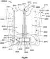
- the photosensitive candle 2000A includes a shell component 2100, a candle container 2200, a candle component 2400, a lighting control component 2500, a light-emitting device 2600 and a light guiding channel 2800.
- the photosensitive candle 2000A does not include an inner container as described earlier in Examples 1-3 above.
- the shell component 2100 includes an outer-shell 2110 for accommodating the candle container 2200, and a filling 2120 disposed between the candle container 2200 and the outer-shell 2110.
- the structures and the arrangements of the outer-shell, the candle container and the filling are generally similar to those as described in Example 1.
- the candle container 2200 may be fixedly housed within the outer-shell 2110.
- the candle container 2200 includes a substantially-flat candle container base 2202 and a candle container opening 2201 opposite the candle container base 2202, and has a central axis (shown as dotted line 2211 in Fig. 4A ) passing through the center of the candle container opening 2201 and the center of the inner container base 2202 and is substantially perpendicular to the candle container base 2202.
- the candle component 2400 and the lighting control component 2500 are both disposed in the candle container 2200.
- the candle component 2400 includes a candle body 2430 filled within the inner container 2300, a wick 2410 and an optical fiber 2420 embedded in the candle body 2300.
- the candle body 2430 is formed by pouring a molten wax into the candle container 2300, thereby embedding at least a part of the wick 2410, the optical fiber 2420 and the lighting control component 2500 within the candle body 2430.
- the candle body 2430 has a top surface 2431 that is substantially aligned with the candle container opening 2201.
- the wick 2410 is arranged substantially perpendicular to the candle container base 2202 along the central axis 2211 and includes a bottom wick end 2412 and an opposing top wick end 2411.
- the wick 2410 has an exposed portion 2413 at the top wick end 2411 protruding out of the top surface 2431 of the candle body 2430.
- the top wick end 2411 is arranged at a level higher than the candle container opening 2201, but lower than the outer-shell opening 2111, such that when the candle is lit, the wick flame can burn stably and be protected from the disturbance of airflow around the photosensitive candle 2000A.
- the optical fiber 2420 is positioned juxtapose to the wick 2410 and arranged parallel to the wick 2410 for transmitting flame lights of the wick 2410.
- the optical fiber 2420 includes a first end 2421 positioned proximate to the exposed portion 2413 of the wick 2410 and an opposing second end 2422.
- the first end 2421 is arranged at a level lower than the top wick end 2411 and the top surface 2431 of the candle body 2430, such that the optical fiber 2420 is embedded entirely in the candle body 2430.
- the lighting control component 2500 includes a casing 2510, a controller 2520, a power source 2530 and a light sensor 2540.
- the casing 2510 has a casing top side 2511 and a casing base 2512 and includes an interior cavity 2513 within the casing 2510.
- the structures and the arrangements of the casing, the controller and the power source disposed within the interior cavity of the casing, and the light sensor are generally similar to those as described in Example 1.
- the light sensor 2540 includes a photosensitive element 2541 protruding outwardly from the upper surface of the casing top side 2511. In this embodiment, the photosensitive element 2541 is positioned proximate to the second end 2422 of the optical fiber 2420 to detect light transmitted therefrom. As shown in Fig.
- the second end 2422 of the optical fiber 2420 and the photosensitive element 2541 are substantially aligned with each other along the central axis 2211 and are positioned as close as possible to each other to allow for a higher degree of light transmission from the optical fiber 2420 to the photosensitive element 2541.
- the second end 2422 of the optical fiber 2420 touches the photosensitive element 2541 such that loss of light intensity during light transmission can be minimized.
- the photosensitive candle 2000A further includes a light guiding channel 2800 disposed within the candle container 2200 and embedded in the candle body 2430.
- the light guiding channel 2800 includes a channel body 2810 configured to accommodate a part of the wick 2410 at the bottom wick end 2412, a part of the optical fiber 2420 at the second end 2422, and at least a part of the photosensitive element 2541 of the light sensor 2540 to guide the light transmission from the second end 2412 of the optical fiber 2420 to the photosensitive element 2541 within the channel body 2810.
- the channel body 2810 are made of non-transparent material for shielding light around the light guiding channel 2800 to avoid any undesired light from reaching the photosensitive element 2541.
- the light guiding channel 2800 may further include a non-transparent sheath 2830 enveloping a part of the optical fiber 2420 at the second end 2422 and at least a part of the photosensitive element 2541.
- the non-transparent sheath 2830 is adapted to avoid influence of environmental light and to prevent light leakage when the light is transmitted from the optical fiber 2420 to the photosensitive element 2541.
- the light guiding channel 2800 may further include a supporting frame 2840 sleeved on the non-transparent sheath 2830 to provide support to the part of the wick 2410 and the optical fiber 2420.
- the supporting frame 2840 can be fittingly inserted into the channel body 2810 (shown in Fig. 4A ) so as to fix the position of the wick 2410 and the optical fiber 2420 within the channel body 2810, so that their position will not be altered when the wax is filled in the candle container 2200 to form the candle body 2430.
- the existence of the channel body 2810, the non-transparent sheath 2830 and/or the supporting frame 2840 creates a wax-free region at the bottom wick end 2412 and the second end 2422 of the optical fiber 2420, thereby preventing the wick flame from reaching the casing 2510 and heating the electronic components housed within the casing 2510 when the wick 2412 is almost burned out, improving the safety when using the photosensitive candle 2000A.
- the light-emitting device 2600 in this embodiment is a light strip that is spiral in shape, including a winding main body 2603 and a connecting end 2601.
- the connecting end 2601 is directly or indirectly connected to the controller 2520 housed within the casing 2510.
- the winding main body 2603 extends out of the casing 2510 and the candle container 2200 and surrounds the exterior surface of the candle container 2200.
- the main body 2603 is at least partially embedded in the filling 2120.
- Fig. 5 shows a photosensitive candle 2000B according to another example embodiment, not part of the claimed invention.
- the photosensitive candle 2000B has a largely similar structure to the photosensitive candle 2000A as described in Example 4.
- the shell component 2100 only consists of the filling 2120 without any additional outer-shell to accommodate the filling 2120.
- the filling 2100 is formed by: (1) placing the candle container 2200 housing the candle component 2400, the light controlling component 2500 and the light guiding channel 2800 into a mold; (2) pouring a molten wax or gel into the mold, thereby embedding the candle container 2200 and all the components housed therein within the filling 2120.
- the filling 2120 has a top filling surface 2123 that is arranged at a level higher than the top surface 2431 of the candle body 2430.
- the wick 2410 has an exposed portion 2413 at the top wick end 2411 protruding out of the top filling surface 2123 to allow the wick flame to be lit.
- the first end 2421 of the optical fiber 2420 is positioned proximate to the exposed portion 2413 and arranged at a level lower than the top filling surface 2123 but higher than the top surface 2431 of the candle body 2430.
- Example 5 has a largely similar structure to the photosensitive candle 2000A as described in Example 4, the feature of the shell component 2100 having only the filling 2120 as described in Example 5 is not limited to being able to replace the corresponding feature of the photosensitive candle of Example 4. It can also be applied to any other examples of the photosensitive candle, including but not limited to the photosensitive candles as described in Examples 1-3 above.
- Fig. 1A Now turning to the operation of the photosensitive candle as described above by referring to Fig. 1A as an example.
- the candle component 1400 is lit by igniting the exposed portion 1413 of the wick 1410 to produce a wick flame, the top surface 1431 of the candle body 1430 made of wax will subsequently melt such that the first end 1421 of the optical fiber 1420 is exposed.
- the flame light of the wick 1410 is transmitted from the first end 1420 to the second end 1422 of the optical fiber 1420, passes through the defined area (labelled as area 1304 in Fig.
- the controller 1520 receives the light signals from the light sensor 1540 and sends driving signals to the light-emitting device 1600 to control the light-emitting device 1600 based on the received light signals.
- the controller 1520 is configured to switch the light-emitting device 1600 from an OFF state to an ON state if the intensity of the light signals is greater than a predetermined threshold.
- the optical fiber 1420 burns together with the wick 1410 when the candle component 1400 is lit. Following the consumption of the wax in the candle body 1430 during the burning process, the lengths of the wick 1410 and the optical fiber 1420 are continuously reduced. As the optical fiber 1420 has a generally lower ignition temperature than the wick 1410, the top end of the optical fiber 1420 is always lower than the top end of the wick 1410 and the wick flame during the burning process, so as to ensure that the flame light of the wick 1410 can always be received by the photosensitive element 1541 to maintain a controlling operation by the controller 1520 on the light-emitting device 1600. If the wick flame is extinguished, no light is detected by the photosensitive element 1541.
- the controller 1520 will not receive any light signals from the light sensor 1540 and may switch off the light-emitting device 1600. If the wick 1410 is ignited again, the flame light of the wick 1410 will again be received by the photosensitive element 1541, and the controller 1520 will be triggered by the light signals received to switch the light-emitting device 1600 from an OFF state to an ON state if the intensity of the light signals is greater than the predetermined threshold.
- controller of the photosensitive candle as described in any of the examples above (including but not limited to Examples 1-5) will now be described in detail.
- the controller may be programmed to operate based on any one of the examples below or any combinations between the examples below.
- Fig. 6 it shows an example embodiment on how the controller controls the switching of the light-emitting device between an ON state and an OFF state.
- the light sensor Before the candle is lit, no light is detected by the light sensor and the light-emitting device is kept in the OFF state in which it does not light up.
- the light sensor When the candle is lit to produce a wick flame, the light sensor generates light signals associated with the flame light of the wick in response to the light detected by the photosensitive element. Therefore, the intensity of the light signals reflects the brightness of the flame light of the wick.
- the controller is configured to receive the light signals associated with the flame light of the wick from the light sensor to control the light-emitting device based on intensity of the light signals.
- the controller compares the intensity of light signals with a predetermined upper threshold S1 and a predetermined lower threshold S2.
- the interval between the predetermined upper threshold S1 and the predetermined lower threshold S2 is referred to as interval P.
- the controller switches the light-emitting device from the OFF state to the ON state, in which the light-emitting device lights up.
- the controller maintains the light-emitting device in the ON state, as long as the intensity of the light signals is greater than the predetermined lower threshold S2. In other words, once the light-emitting device is switched to the ON state, the light-emitting device will be kept in the ON state if the intensity of light signals falls within the interval P or greater than the predetermined upper threshold S1.
- the controller if the intensity of the light signals drops to a value lesser than the predetermined lower threshold S2, the controller is configured to switch the light-emitting device from the ON state to the OFF state. Once the light-emitting device is switched to the OFF state, the controller maintains the light-emitting device in the OFF state, as long as the intensity of the light signals is lesser than the predetermined upper threshold S 1. In other words, once the light-emitting device is switched to the OFF state, the light-emitting device will be kept in the OFF state if the intensity of light signals falls within the interval P or lesser than the predetermined upper threshold S 1. If the intensity of the light signals rises again to a value greater than the predetermined upper threshold S1, the controller will again switch the light-emitting device from the OFF state to the ON state as described above.
- the configuration of the predetermined upper threshold S1, the predetermined lower threshold S2 and the interval P as described above ensures that the illumination of the light-emitting device can be maintained at a stable manner compared to configuration with only one threshold value that determines the switching on/off of the light-emitting device.
- a higher intensity of light is required to switch on the light-emitting device, whereas when the candle component is burning normally, the light-emitting device will be switched off only when the intensity of light reduces to a lower value, thereby avoiding the constant switching of the light-emitting device from the ON state to the OFF state and maintaining the stability of the illumination of the light-emitting device during use.
- the delayed switching off function can be applied to the configuration as described in Example 6 if the intensity of the light signals drops to a value lesser than the predetermined lower threshold S2.
- the delayed switching off function can be an independent function that is executed by the controller.
- the controller compares the intensity of light signals with a predetermined threshold S.
- the predetermined threshold S can be the predetermined lower threshold S2 as described in Example 6 above.
- the controller if the intensity of the light signals is greater than the predetermined threshold S, the controller generates two signals (referred as signal 1 and a signal 2) and control the ON-OFF state of the light-emitting device based on the two signals.
- Signal 1 is an indication of the real-time intensity of light signals comparing with the predetermined threshold S, where any intensity of light signals above the predetermined threshold S actives signal 1 and any intensity of light signals below the predetermined threshold S deactives signal 1.
- Signal 2 is an indication with delay of the intensity of light signals comparing with the predetermined threshold S.
- the controller generates the signals to switch the light-emitting device from the OFF state to the ON state only when the intensity of light signals is greater than a predetermined upper threshold, as described in Example 6 above.
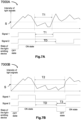
- the intensity of the light signals drops to a value lesser than the predetermined threshold S, signal 1 will be deactivated instantly while signal 2 remains active for a predetermined period of time TD.
- the light-emitting device will be maintained in the ON state as long as at least one of the signal 1 and signal 2 remains active.
- the length of time T1 is shorter than the predetermined period of time TD, signal 2 will remain active at least throughout the period of time TD, thereby maintaining the light-emitting device in the ON state.
- the intensity of the light signals rises again to a value greater than the predetermined threshold S, signal 1 will be activated again instantly, and therefore the light-emitting device will be kept in the ON state.
- the intensity of the light signals maintains below the predetermined threshold S for a length of time T2.
- signal 1 will be deactivated instantly while signal 2 remains active for a predetermined period of time TD.
- the length of time T2 is longer than the predetermined period of time TD as shown in Fig. 7B
- signal 2 will be deactivated after remaining active for the predetermined period of time TD.
- both signal 1 and signal 2 is not active during the period (labelled as T3 in Fig.
- the controller activates signal 1 and signal 2 again to switch the light-emitting device from the OFF state to the ON state.
- the controller is configured to start a timer once the intensity of the light signals drops to a value lesser than the predetermined threshold S and end the timer once the intensity of the light signals increases to a value greater than the predetermined threshold S, to measure a length of time in which the intensity of the light signals is lesser than the predetermined threshold S.
- the controller may measure the time of T1 and if T1 is less than TD, it controls the light-emitting device to maintain in the ON state.
- the controller may measure the time of T2 and once T2 surpasses TD, it controls the light-emitting device to switch from the ON state to the OFF state. In this way, the delayed switching off function of the light-emitting device is enabled to avoid temporary disturbance on the candle from the environment.
- the specific predetermined period of time TD can be set according to the preference of the user. In some embodiments, the predetermined period of time TD is set at a value between 1 second to 6 seconds. In some embodiments, the predetermined period of time TD is set at a value between 2 seconds to 5 seconds. In a specific embodiment, the predetermined period of time TD is set as 4 seconds.
- the configuration of the delayed switching off function as described above ensures that the light-emitting device will be switched from an ON state to an OFF state only if the intensity of the light signals is lesser than the predetermined lower threshold for a predetermined period of time, thereby avoiding undesirable switching off of the light-emitting device when the flame light of the wick are temporarily diminished (but not extinguished) by a disturbance of airflow around the photosensitive candle.
- the light-emitting device can illuminate stably and continuously.
- the light control component may comprise one or more additional electrical components connected to the controller such that when the light-emitting device is in the ON state, the controller can be configured to control an illumination of the light-emitting device based on one or more different light modes. Some examples of these light modes are described in detail below.
- the lighting control component further comprises an analog-digital converting module connected to the controller.
- the analog-digital converting module is configured to (i) analyze and process the light signals to generate digital signals, wherein the digital signals represent the intensity of the light signals, and (ii) transmit the digital signals to the controller.
- the controller is configured to control an illumination of the light-emitting device based on the digital signals received from the analog-digital converting module when the light-emitting device is in the ON state.
- the controller when the controller receives the light signals associated with the flame lights of the wick from the light sensor, the controller passes the light signals to the analog-digital converting module.
- the analog-digital converting module performs analog/digital conversion of the light signals received by analyzing and processing the light signals to generate digital signals.
- the digital signals represent the intensity of the light signals.
- the digital signals will then be transmitted back to the controller, in which the controller controls an illumination of the light-emitting device based on the digital signals received.
- the luminescence e.g.
- brightness, light output, color temperature, etc.) and/or light pattern (e.g. change of color, frequency of flashing the light, etc.) of the light-emitting device will vary with the change in the intensity of the light signals received, thereby synchronizing the illumination of the light-emitting device with the flickering of the flame lights of the wick.
- Light mode 2 Independent illumination mode
- the controller comprises a memory (such as random access memory (RAM), read only memory (ROM), and/or firmware) that stores a preset program, and the controller is configured to control an illumination of the light-emitting device based on the preset program when the light-emitting device is in the ON state.
- the preset program may direct the controller to generate driving signals in accordance with pulse-width modulation (PWM) signals modulated by specific codes to drive the illumination of the light-emitting device.
- PWM pulse-width modulation
- the preset program may determine the brightness of the light-emitting device, the change of color, the frequency of flashing the light and/or other light patterns.
- the light-emitting device After the candle component is lit to switch the light-emitting device to the ON state, the light-emitting device illuminates according to the preset program that is independent from the intensity of the light signals received. When the wick flame is extinguished, the light-emitting device switches off and the illumination of the light-emitting device stops automatically.
- the outer-shell, the inner-shell, the candle container, the inner-container in example embodiments above are described as having a cup-shape, but other shapes and designs may be used according to the user's preference, as long as an opening is provided in these shapes to ensure that the wick flame can be lit and maintained within the photosensitive candle.
- the photosensitive candle in the embodiments above includes a light-emitting device (e.g. light strip) that are connected to the controller.
- the photosensitive candle may include two or more light-emitting devices that are removably or irremovably connected with the controller.
- the two or more light-emitting devices may comprises LED with different colors.
- the light-emitting device 1600 in Example 1 is a light strip that is spiral in shape, including a winding main body 1603 extending out of the casing 1510 and the candle container 1200 and surrounding the exterior surface of the candle container 1200.
- the light-emitting device can be any device in any shapes, including but not limited to a light emitting diode (LED), a light bulb, a light ring, a light block, a light string and a light tube, as long as it is configured to emit light or having a light-emitting element or the like.
- LED light emitting diode
Landscapes
- Engineering & Computer Science (AREA)
- Chemical & Material Sciences (AREA)
- General Engineering & Computer Science (AREA)
- Physics & Mathematics (AREA)
- General Physics & Mathematics (AREA)
- Optics & Photonics (AREA)
- Life Sciences & Earth Sciences (AREA)
- General Chemical & Material Sciences (AREA)
- Chemical Kinetics & Catalysis (AREA)
- Oil, Petroleum & Natural Gas (AREA)
- Wood Science & Technology (AREA)
- Organic Chemistry (AREA)
- Composite Materials (AREA)
- Arrangement Of Elements, Cooling, Sealing, Or The Like Of Lighting Devices (AREA)
Claims (11)
- - Bougie photosensible (1000A) comprenant :(a) un récipient de bougie (1200) comprenant une ouverture (1201) ;(b) un composant de bougie (1400) disposé dans le récipient de bougie (1200), comprenant :un corps de bougie (1430) ayant une surface (1431) proche ou sensiblement alignée avec l'ouverture (1201) ;une mèche (1410) avec une partie exposée (1413) faisant saillie hors de la surface (1431) du corps de bougie (1430) ; etune fibre optique (1420) intégrée dans le corps de bougie (1430) et positionnée juxtaposée à la mèche (1410) pour transmettre des lumières de flamme de la mèche (1410), la fibre optique (1420) comprenant une première extrémité (1421) proche de la partie exposée (1413) de la mèche (1410) et une seconde extrémité opposée (1422) ;(c) un composant de commande d'éclairage (1500) disposé dans le récipient de bougie (1200), comprenant :une enveloppe (1510) comprenant une cavité intérieure (1513) ;un dispositif de contrôle (1520) et une source d'énergie (1530) disposés à l'intérieur de la cavité intérieure (1513) ; etun capteur de lumière (1540) relié au dispositif de contrôle (1520), comprenant un élément photosensible (1541) proche de la seconde extrémité (1422) de la fibre optique (1420) pour détecter de la lumière transmise par celle-ci ; et(d) au moins un dispositif émetteur de lumière (1600) relié au dispositif de contrôle (1520) ;le dispositif de contrôle (1520) étant configuré pour :(i) recevoir, en provenance du capteur de lumière (1540), des signaux lumineux associés aux lumières de flamme de la mèche (1410) ;(ii) faire passer l'au moins un dispositif émetteur de lumière (1600) d'un état d'arrêt à un état de marche si une intensité des signaux lumineux est supérieure à un seuil supérieur prédéterminé ;(iii) maintenir l'au moins un dispositif émetteur de lumière (1600) à l'état de marche si l'au moins un dispositif émetteur de lumière (1600) est à l'état de marche et l'intensité des signaux lumineux est supérieure à un seuil inférieur prédéterminé ;(iv) faire passer l'au moins un dispositif émetteur de lumière (1600) de l'état de marche à l'état d'arrêt si l'intensité des signaux lumineux est inférieure au seuil inférieur prédéterminé pendant une période de temps prédéterminée ; et(v) maintenir l'au moins un dispositif émetteur de lumière (1600) à l'état d'arrêt si l'au moins un dispositif émetteur de lumière (1600) est à l'état d'arrêt et l'intensité des signaux lumineux est inférieure au seuil supérieur prédéterminé ;la bougie photosensible (1000A) comprenant en outre :un récipient intérieur (1300) reçu à l'intérieur du récipient de bougie (1200), comprenant une base de récipient intérieur (1302) positionnée au-dessus de l'enveloppe (1510) du composant de commande d'éclairage (1500), le composant de bougie (1400) étant disposé à l'intérieur du récipient intérieur (1300) ;un canal de guidage de lumière (1800) fixé à une zone définie (1304) de la base de récipient intérieur (1302), comprenant :une première partie (1810) disposée à l'intérieur du récipient intérieur (1300), configurée pour recevoir une partie de la mèche (1410) et la seconde extrémité (1422) de la fibre optique (1420) ; etune seconde partie (1820) disposée à l'extérieur du récipient intérieur (1300) et s'étendant à l'opposé de la base de récipient intérieur (1302), configurée pour recevoir au moins une partie de l'élément photosensible (1541) du capteur de lumière (1540) ;la seconde extrémité (1422) de la fibre optique (1420) et l'élément photosensible (1541) étant séparés l'un de l'autre par la zone définie (1304) de la base de récipient intérieur (1302), etla zone définie (1304) de la base de récipient intérieur (1302) étant faite d'un matériau transparent, et la première partie (1810) et la seconde partie (1820) du canal de guidage de lumière (1800) étant sensiblement alignées l'une avec l'autre, de telle sorte que la lumière transmise par la fibre optique (1420) peut être détectée par l'élément photosensible (1541).
- - Bougie photosensible (1000A) selon la revendication 1, dans laquelle le composant de commande d'éclairage (1500) comprend en outre un module de conversion analogique-numérique relié au dispositif de contrôle (1520), le module de conversion analogique-numérique étant configuré pour :(i) analyser et traiter les signaux lumineux pour générer des signaux numériques, les signaux numériques représentant l'intensité des signaux lumineux ; et(ii) transmettre les signaux numériques au dispositif de contrôle (1520),le dispositif de contrôle (1520) étant en outre configuré pour contrôler une illumination de l'au moins un dispositif émetteur de lumière (1600) sur la base des signaux numériques reçus en provenance du module de conversion analogique-numérique lorsque l'au moins un dispositif émetteur de lumière (1600) est à l'état de marche.
- - Bougie photosensible (1000A) selon la revendication 1, dans laquelle le composant de commande d'éclairage (1500) comprend en outre une mémoire qui stocke un programme prédéfini, et le dispositif de contrôle (1520) est en outre configuré pour contrôler une illumination de l'au moins un dispositif émetteur de lumière (1600) sur la base du programme prédéfini lorsque l'au moins un dispositif émetteur de lumière (1600) est à l'état de marche.
- - Bougie photosensible (1000A) selon la revendication 1, dans laquelle la période de temps prédéterminée est comprise entre 1 seconde et 6 secondes.
- - Bougie photosensible (1000A) selon la revendication 1, dans laquelle le récipient de bougie (1200) comprend en outre une base de récipient de bougie (1202) à l'opposé de l'ouverture (1201), et la bougie photosensible (1000A) comprend en outre un composant coque (1100) comprenant :une coque extérieure (1110) comprenant une base de coque extérieure (1112), la coque extérieure (1110) étant configurée pour recevoir le récipient de bougie (1200) avec la base de récipient de bougie (1202) disposée sur le dessus de la base de coque extérieure (1112) ; etune garniture (1120) qui remplit un espace entre le récipient de bougie (1200) et la coque extérieure (1110),l'au moins un dispositif émetteur de lumière (1600) comprenant un corps principal (1603) s'étendant hors de l'enveloppe (1510) et du récipient de bougie (1200) et est au moins partiellement intégré dans le remplissage (1120).
- - Bougie photosensible (1000A) selon la revendication 5, comprenant en outre :un trou de coque extérieure (1114) formé sur la base de coque extérieure (1112) ;un trou de récipient de bougie (1204) formé sur la base de récipient de bougie (1202) ;un trou d'enveloppe (1514) formé sur l'enveloppe (1510) ; etun couvercle amovible (1550) pour recouvrir le trou de coque extérieure (1114) ;le trou de coque extérieure (1114), le trou de récipient de bougie (1204) et le trou d'enveloppe (1514) étant sensiblement alignés les uns avec les autres de telle sorte que la cavité intérieure (1513) de l'enveloppe (1510) est accessible par un utilisateur lorsque le couvercle amovible (1550) est ouvert.
- - Bougie photosensible (1000A) selon la revendication 1, dans laquelle le récipient de bougie (1200) comprend en outre une base de récipient de bougie (1202) à l'opposé de l'ouverture (1201), et la bougie photosensible (1000A) comprend en outre un composant coque (1100) comprenant :une coque extérieure (1110) comprenant une base de coque extérieure (1112) ;une coque intérieure (1130) comprenant une base de coque intérieure (1132), la coque intérieure (1130) étant reçue à l'intérieur de la coque extérieure (1110) avec la base de coque intérieure (1132) disposée sur le dessus de la base de coque extérieure (1112), et la coque intérieure (1130) étant configurée pour recevoir de manière amovible le récipient de bougie (1200) avec la base de récipient de bougie (1202) disposée sur le dessus de la base de coque intérieure (1132) ; etune garniture (1120) qui remplit un espace entre la coque intérieure (1130) et la coque extérieure (1110),l'au moins un dispositif émetteur de lumière (1600) comprenant un corps principal (1603) s'étendant hors de l'enveloppe (1510), du récipient de bougie (1200) et de la coque intérieure (1130) et est au moins partiellement intégré dans le remplissage (1120).
- - Bougie photosensible (1000A) selon la revendication 7, comprenant en outre :un trou de récipient de bougie (1204) formé sur la base de récipient de bougie (1202) ;un trou d'enveloppe (1514) formé sur l'enveloppe (1510) ; etun couvercle amovible (1550) pour recouvrir le trou de récipient de bougie (1204) ;le trou de récipient de bougie (1204) et le trou d'enveloppe (1514) étant sensiblement alignés l'un avec l'autre, de telle sorte que la cavité intérieure (1513) de l'enveloppe (1510) est accessible par un utilisateur lorsque le récipient de bougie (1200) est retiré de la coque intérieure (1130) et le couvercle amovible (1550) est ouvert.
- - Bougie photosensible (1000A) selon la revendication 1, dans laquelle l'au moins un dispositif émetteur de lumière (1600) comprend au moins deux guirlandes d'illumination de couleurs différentes.
- - Bougie photosensible (1000A) selon la revendication 7, dans laquelle
au moins un dispositif émetteur de lumière (1600) comprend une extrémité de liaison (1601) et un corps principal (1603), l'extrémité de liaison (1601) étant reliée au dispositif de contrôle (1520) et le corps principal (1603) s'étendant hors de l'enveloppe (1510). - - Bougie photosensible (1000A) selon la revendication 1, dans laquelle le dispositif de contrôle (1520) est en outre configuré pour effectuer les étapes suivantes :si l'intensité des signaux lumineux devient inférieure au seuil inférieur prédéterminé lorsque l'au moins un dispositif émetteur de lumière (1600) est à l'état de marche, mesurer une durée pendant laquelle l'intensité des signaux lumineux est inférieure au seuil inférieur prédéterminé ; etsi la durée est inférieure à une période de temps prédéterminée, maintenir l'au moins un dispositif émetteur de lumière (1600) à l'état de marche ;si la durée est supérieure à la période de temps prédéterminée, faire passer l'au moins un dispositif émetteur de lumière (1600) de l'état de marche à l'état d'arrêt.
Applications Claiming Priority (1)
| Application Number | Priority Date | Filing Date | Title |
|---|---|---|---|
| US17/445,498 US11448373B1 (en) | 2021-08-20 | 2021-08-20 | Photosensitive candle |
Publications (2)
| Publication Number | Publication Date |
|---|---|
| EP4137741A1 EP4137741A1 (fr) | 2023-02-22 |
| EP4137741B1 true EP4137741B1 (fr) | 2024-10-16 |
Family
ID=78649148
Family Applications (1)
| Application Number | Title | Priority Date | Filing Date |
|---|---|---|---|
| EP21207464.5A Active EP4137741B1 (fr) | 2021-08-20 | 2021-11-10 | Bougie photosensible |
Country Status (2)
| Country | Link |
|---|---|
| US (1) | US11448373B1 (fr) |
| EP (1) | EP4137741B1 (fr) |
Families Citing this family (5)
| Publication number | Priority date | Publication date | Assignee | Title |
|---|---|---|---|---|
| GB2624728A (en) * | 2022-11-18 | 2024-05-29 | Gianthope Arts Product Huizhou Company Ltd | Candle device |
| WO2024105416A1 (fr) * | 2022-11-18 | 2024-05-23 | Gianthope Arts Product (Huizhou) Co Limited | Dispositif de bougie |
| WO2024246553A1 (fr) * | 2023-06-02 | 2024-12-05 | Gianthope Arts Product (Huizhou) Co Limited | Élément d'éclairage |
| CN116624820A (zh) * | 2023-06-02 | 2023-08-22 | 炬锵工艺制品(惠州)有限公司 | 照明元件 |
| CN221881389U (zh) | 2024-03-28 | 2024-10-22 | 黄立伟 | 具有自动灯光效果的生日蜡烛 |
Family Cites Families (11)
| Publication number | Priority date | Publication date | Assignee | Title |
|---|---|---|---|---|
| US4477249A (en) | 1983-04-29 | 1984-10-16 | Zdenka Ruzek | Flame-producing sound-emitting device |
| CN2462235Y (zh) | 2000-12-26 | 2001-11-28 | 程哲明 | 一种烛台 |
| CN2777350Y (zh) * | 2005-02-06 | 2006-05-03 | 胡婷 | 发光蜡罐 |
| US20070003894A1 (en) * | 2005-06-29 | 2007-01-04 | Shung-Lun Yu | Electronic candle |
| JP4619264B2 (ja) | 2005-10-28 | 2011-01-26 | 浅野 信博 | 音声再生型ローソク立て装置 |
| JP3177575U (ja) | 2012-05-29 | 2012-08-09 | 不二貿易株式会社 | 蝋発光式キャンドル |
| PL403888A1 (pl) | 2013-05-15 | 2014-11-24 | Korona Spółka Akcyjna | Lampion LED |
| MY178214A (en) | 2015-10-07 | 2020-10-07 | Luminous Global Trading | A device with color changing effect |
| CN205535250U (zh) | 2016-03-23 | 2016-08-31 | 杭州顺安实业有限公司 | 一种光控变色蜡烛 |
| CN209054487U (zh) | 2018-09-27 | 2019-07-02 | 饶沅樟 | 能呈现全像光学图案化影像的烛座 |
| CN211170633U (zh) | 2019-11-21 | 2020-08-04 | 华智科技(国际)有限公司 | 一种光控可燃蜡烛 |
-
2021
- 2021-08-20 US US17/445,498 patent/US11448373B1/en active Active
- 2021-11-10 EP EP21207464.5A patent/EP4137741B1/fr active Active
Also Published As
| Publication number | Publication date |
|---|---|
| EP4137741A1 (fr) | 2023-02-22 |
| US11448373B1 (en) | 2022-09-20 |
Similar Documents
| Publication | Publication Date | Title |
|---|---|---|
| EP4137741B1 (fr) | Bougie photosensible | |
| CA2634253C (fr) | Ensemble de bougie comprenant un systeme d'illumination | |
| US7699603B2 (en) | Multisensory candle assembly | |
| US7098600B2 (en) | Candle with internal illumination | |
| US7637737B2 (en) | Candle assembly with light emitting system | |
| US20070020572A1 (en) | Candle and luminary light show | |
| EP0146247A2 (fr) | Dispositif d'éclairage | |
| WO2000022346A1 (fr) | Bougie emettant des sons | |
| KR20070072238A (ko) | 멜로디발광양초 | |
| US7252423B1 (en) | Candle with magnetically activated internal illumination | |
| CN118057074A (zh) | 蜡烛装置 | |
| US20070003894A1 (en) | Electronic candle | |
| KR101192141B1 (ko) | Led를 이용한 양초 | |
| KR102458833B1 (ko) | 조명기구 기능 겸용 led 발열을 이용하여 디퓨져 기능을 갖도록 한 향초 | |
| KR101005154B1 (ko) | 발광양초 및 이의 제조방법 | |
| JP3177575U (ja) | 蝋発光式キャンドル | |
| KR102540223B1 (ko) | 다기능 휴대용 회전손전등 | |
| CN211170633U (zh) | 一种光控可燃蜡烛 | |
| KR102066037B1 (ko) | 광 생성 장치 | |
| AU2006331866A1 (en) | Candle and luminary light show | |
| CN2799563Y (zh) | 变色蜡烛 | |
| KR20200118751A (ko) | 광 생성 장치 | |
| GB2624728A (en) | Candle device | |
| AU2004100922A4 (en) | An Electric Candle | |
| WO2024105416A1 (fr) | Dispositif de bougie |
Legal Events
| Date | Code | Title | Description |
|---|---|---|---|
| PUAI | Public reference made under article 153(3) epc to a published international application that has entered the european phase |
Free format text: ORIGINAL CODE: 0009012 |
|
| STAA | Information on the status of an ep patent application or granted ep patent |
Free format text: STATUS: REQUEST FOR EXAMINATION WAS MADE |
|
| 17P | Request for examination filed |
Effective date: 20221013 |
|
| AK | Designated contracting states |
Kind code of ref document: A1 Designated state(s): AL AT BE BG CH CY CZ DE DK EE ES FI FR GB GR HR HU IE IS IT LI LT LU LV MC MK MT NL NO PL PT RO RS SE SI SK SM TR |
|
| GRAP | Despatch of communication of intention to grant a patent |
Free format text: ORIGINAL CODE: EPIDOSNIGR1 |
|
| STAA | Information on the status of an ep patent application or granted ep patent |
Free format text: STATUS: GRANT OF PATENT IS INTENDED |
|
| RIC1 | Information provided on ipc code assigned before grant |
Ipc: F21Y 115/10 20160101ALN20240409BHEP Ipc: F21Y 103/30 20160101ALN20240409BHEP Ipc: F21V 8/00 20060101ALI20240409BHEP Ipc: F21V 35/00 20060101ALI20240409BHEP Ipc: F21V 23/04 20060101ALI20240409BHEP Ipc: F21V 19/04 20060101ALI20240409BHEP Ipc: F21S 19/00 20060101AFI20240409BHEP |
|
| INTG | Intention to grant announced |
Effective date: 20240515 |
|
| GRAS | Grant fee paid |
Free format text: ORIGINAL CODE: EPIDOSNIGR3 |
|
| GRAA | (expected) grant |
Free format text: ORIGINAL CODE: 0009210 |
|
| STAA | Information on the status of an ep patent application or granted ep patent |
Free format text: STATUS: THE PATENT HAS BEEN GRANTED |
|
| AK | Designated contracting states |
Kind code of ref document: B1 Designated state(s): AL AT BE BG CH CY CZ DE DK EE ES FI FR GB GR HR HU IE IS IT LI LT LU LV MC MK MT NL NO PL PT RO RS SE SI SK SM TR |
|
| REG | Reference to a national code |
Ref country code: GB Ref legal event code: FG4D |
|
| REG | Reference to a national code |
Ref country code: CH Ref legal event code: EP |
|
| REG | Reference to a national code |
Ref country code: IE Ref legal event code: FG4D |
|
| REG | Reference to a national code |
Ref country code: DE Ref legal event code: R096 Ref document number: 602021020286 Country of ref document: DE |
|
| REG | Reference to a national code |
Ref country code: CH Ref legal event code: PK Free format text: BERICHTIGUNGEN |
|
| RAP2 | Party data changed (patent owner data changed or rights of a patent transferred) |
Owner name: VITELIC TECHNOLOGY (INTERNATIONAL) LIMITED |
|
| REG | Reference to a national code |
Ref country code: DE Ref legal event code: R081 Ref document number: 602021020286 Country of ref document: DE Owner name: VITELIC TECHNOLOGY ( INTERNATIONAL) LTD., SHAT, HK Free format text: FORMER OWNER: CHAN, LAP CHI, SHATIN, N.T., HK |
|
| RIN2 | Information on inventor provided after grant (corrected) |
Inventor name: CHAN, LAP CHI |
|
| REG | Reference to a national code |
Ref country code: LT Ref legal event code: MG9D |
|
| REG | Reference to a national code |
Ref country code: GB Ref legal event code: 732E Free format text: REGISTERED BETWEEN 20250116 AND 20250122 |
|
| REG | Reference to a national code |
Ref country code: NL Ref legal event code: MP Effective date: 20241016 |
|
| REG | Reference to a national code |
Ref country code: AT Ref legal event code: MK05 Ref document number: 1733168 Country of ref document: AT Kind code of ref document: T Effective date: 20241016 |
|
| PG25 | Lapsed in a contracting state [announced via postgrant information from national office to epo] |
Ref country code: NL Free format text: LAPSE BECAUSE OF FAILURE TO SUBMIT A TRANSLATION OF THE DESCRIPTION OR TO PAY THE FEE WITHIN THE PRESCRIBED TIME-LIMIT Effective date: 20241016 |
|
| PG25 | Lapsed in a contracting state [announced via postgrant information from national office to epo] |
Ref country code: NL Free format text: LAPSE BECAUSE OF FAILURE TO SUBMIT A TRANSLATION OF THE DESCRIPTION OR TO PAY THE FEE WITHIN THE PRESCRIBED TIME-LIMIT Effective date: 20241016 |
|
| PG25 | Lapsed in a contracting state [announced via postgrant information from national office to epo] |
Ref country code: IS Free format text: LAPSE BECAUSE OF FAILURE TO SUBMIT A TRANSLATION OF THE DESCRIPTION OR TO PAY THE FEE WITHIN THE PRESCRIBED TIME-LIMIT Effective date: 20250216 Ref country code: HR Free format text: LAPSE BECAUSE OF FAILURE TO SUBMIT A TRANSLATION OF THE DESCRIPTION OR TO PAY THE FEE WITHIN THE PRESCRIBED TIME-LIMIT Effective date: 20241016 Ref country code: PT Free format text: LAPSE BECAUSE OF FAILURE TO SUBMIT A TRANSLATION OF THE DESCRIPTION OR TO PAY THE FEE WITHIN THE PRESCRIBED TIME-LIMIT Effective date: 20250217 |
|
| PG25 | Lapsed in a contracting state [announced via postgrant information from national office to epo] |
Ref country code: FI Free format text: LAPSE BECAUSE OF FAILURE TO SUBMIT A TRANSLATION OF THE DESCRIPTION OR TO PAY THE FEE WITHIN THE PRESCRIBED TIME-LIMIT Effective date: 20241016 |
|
| PG25 | Lapsed in a contracting state [announced via postgrant information from national office to epo] |
Ref country code: BG Free format text: LAPSE BECAUSE OF FAILURE TO SUBMIT A TRANSLATION OF THE DESCRIPTION OR TO PAY THE FEE WITHIN THE PRESCRIBED TIME-LIMIT Effective date: 20241016 |
|
| PG25 | Lapsed in a contracting state [announced via postgrant information from national office to epo] |
Ref country code: ES Free format text: LAPSE BECAUSE OF FAILURE TO SUBMIT A TRANSLATION OF THE DESCRIPTION OR TO PAY THE FEE WITHIN THE PRESCRIBED TIME-LIMIT Effective date: 20241016 |
|
| PG25 | Lapsed in a contracting state [announced via postgrant information from national office to epo] |
Ref country code: NO Free format text: LAPSE BECAUSE OF FAILURE TO SUBMIT A TRANSLATION OF THE DESCRIPTION OR TO PAY THE FEE WITHIN THE PRESCRIBED TIME-LIMIT Effective date: 20250116 |
|
| PG25 | Lapsed in a contracting state [announced via postgrant information from national office to epo] |
Ref country code: AT Free format text: LAPSE BECAUSE OF FAILURE TO SUBMIT A TRANSLATION OF THE DESCRIPTION OR TO PAY THE FEE WITHIN THE PRESCRIBED TIME-LIMIT Effective date: 20241016 Ref country code: LV Free format text: LAPSE BECAUSE OF FAILURE TO SUBMIT A TRANSLATION OF THE DESCRIPTION OR TO PAY THE FEE WITHIN THE PRESCRIBED TIME-LIMIT Effective date: 20241016 Ref country code: GR Free format text: LAPSE BECAUSE OF FAILURE TO SUBMIT A TRANSLATION OF THE DESCRIPTION OR TO PAY THE FEE WITHIN THE PRESCRIBED TIME-LIMIT Effective date: 20250117 |
|
| PG25 | Lapsed in a contracting state [announced via postgrant information from national office to epo] |
Ref country code: PL Free format text: LAPSE BECAUSE OF FAILURE TO SUBMIT A TRANSLATION OF THE DESCRIPTION OR TO PAY THE FEE WITHIN THE PRESCRIBED TIME-LIMIT Effective date: 20241016 |
|
| PG25 | Lapsed in a contracting state [announced via postgrant information from national office to epo] |
Ref country code: RS Free format text: LAPSE BECAUSE OF FAILURE TO SUBMIT A TRANSLATION OF THE DESCRIPTION OR TO PAY THE FEE WITHIN THE PRESCRIBED TIME-LIMIT Effective date: 20250116 |
|
| REG | Reference to a national code |
Ref country code: CH Ref legal event code: PL |
|
| PG25 | Lapsed in a contracting state [announced via postgrant information from national office to epo] |
Ref country code: SM Free format text: LAPSE BECAUSE OF FAILURE TO SUBMIT A TRANSLATION OF THE DESCRIPTION OR TO PAY THE FEE WITHIN THE PRESCRIBED TIME-LIMIT Effective date: 20241016 |
|
| PG25 | Lapsed in a contracting state [announced via postgrant information from national office to epo] |
Ref country code: MC Free format text: LAPSE BECAUSE OF FAILURE TO SUBMIT A TRANSLATION OF THE DESCRIPTION OR TO PAY THE FEE WITHIN THE PRESCRIBED TIME-LIMIT Effective date: 20241016 |
|
| PG25 | Lapsed in a contracting state [announced via postgrant information from national office to epo] |
Ref country code: DK Free format text: LAPSE BECAUSE OF FAILURE TO SUBMIT A TRANSLATION OF THE DESCRIPTION OR TO PAY THE FEE WITHIN THE PRESCRIBED TIME-LIMIT Effective date: 20241016 |
|
| PG25 | Lapsed in a contracting state [announced via postgrant information from national office to epo] |
Ref country code: LU Free format text: LAPSE BECAUSE OF NON-PAYMENT OF DUE FEES Effective date: 20241110 |
|
| REG | Reference to a national code |
Ref country code: CH Ref legal event code: PL |
|
| REG | Reference to a national code |
Ref country code: DE Ref legal event code: R097 Ref document number: 602021020286 Country of ref document: DE |
|
| PG25 | Lapsed in a contracting state [announced via postgrant information from national office to epo] |
Ref country code: EE Free format text: LAPSE BECAUSE OF FAILURE TO SUBMIT A TRANSLATION OF THE DESCRIPTION OR TO PAY THE FEE WITHIN THE PRESCRIBED TIME-LIMIT Effective date: 20241016 |
|
| PG25 | Lapsed in a contracting state [announced via postgrant information from national office to epo] |
Ref country code: CH Free format text: LAPSE BECAUSE OF NON-PAYMENT OF DUE FEES Effective date: 20241130 |
|
| PG25 | Lapsed in a contracting state [announced via postgrant information from national office to epo] |
Ref country code: RO Free format text: LAPSE BECAUSE OF FAILURE TO SUBMIT A TRANSLATION OF THE DESCRIPTION OR TO PAY THE FEE WITHIN THE PRESCRIBED TIME-LIMIT Effective date: 20241016 |
|
| PG25 | Lapsed in a contracting state [announced via postgrant information from national office to epo] |
Ref country code: SK Free format text: LAPSE BECAUSE OF FAILURE TO SUBMIT A TRANSLATION OF THE DESCRIPTION OR TO PAY THE FEE WITHIN THE PRESCRIBED TIME-LIMIT Effective date: 20241016 |
|
| PG25 | Lapsed in a contracting state [announced via postgrant information from national office to epo] |
Ref country code: CZ Free format text: LAPSE BECAUSE OF FAILURE TO SUBMIT A TRANSLATION OF THE DESCRIPTION OR TO PAY THE FEE WITHIN THE PRESCRIBED TIME-LIMIT Effective date: 20241016 |
|
| PG25 | Lapsed in a contracting state [announced via postgrant information from national office to epo] |
Ref country code: IT Free format text: LAPSE BECAUSE OF FAILURE TO SUBMIT A TRANSLATION OF THE DESCRIPTION OR TO PAY THE FEE WITHIN THE PRESCRIBED TIME-LIMIT Effective date: 20241016 |
|
| PLBE | No opposition filed within time limit |
Free format text: ORIGINAL CODE: 0009261 |
|
| STAA | Information on the status of an ep patent application or granted ep patent |
Free format text: STATUS: NO OPPOSITION FILED WITHIN TIME LIMIT |
|
| REG | Reference to a national code |
Ref country code: BE Ref legal event code: MM Effective date: 20241130 |
|
| PG25 | Lapsed in a contracting state [announced via postgrant information from national office to epo] |
Ref country code: SE Free format text: LAPSE BECAUSE OF FAILURE TO SUBMIT A TRANSLATION OF THE DESCRIPTION OR TO PAY THE FEE WITHIN THE PRESCRIBED TIME-LIMIT Effective date: 20241016 |
|
| 26N | No opposition filed |
Effective date: 20250717 |
|
| PG25 | Lapsed in a contracting state [announced via postgrant information from national office to epo] |
Ref country code: BE Free format text: LAPSE BECAUSE OF NON-PAYMENT OF DUE FEES Effective date: 20241130 |
|
| PG25 | Lapsed in a contracting state [announced via postgrant information from national office to epo] |
Ref country code: FR Free format text: LAPSE BECAUSE OF NON-PAYMENT OF DUE FEES Effective date: 20241216 |
|
| PG25 | Lapsed in a contracting state [announced via postgrant information from national office to epo] |
Ref country code: IE Free format text: LAPSE BECAUSE OF NON-PAYMENT OF DUE FEES Effective date: 20241110 |
|
| PGFP | Annual fee paid to national office [announced via postgrant information from national office to epo] |
Ref country code: DE Payment date: 20251124 Year of fee payment: 5 |
|
| PGFP | Annual fee paid to national office [announced via postgrant information from national office to epo] |
Ref country code: GB Payment date: 20251126 Year of fee payment: 5 |
|
| PG25 | Lapsed in a contracting state [announced via postgrant information from national office to epo] |
Ref country code: HU Free format text: LAPSE BECAUSE OF FAILURE TO SUBMIT A TRANSLATION OF THE DESCRIPTION OR TO PAY THE FEE WITHIN THE PRESCRIBED TIME-LIMIT; INVALID AB INITIO Effective date: 20211110 |
|
| PG25 | Lapsed in a contracting state [announced via postgrant information from national office to epo] |
Ref country code: CY Free format text: LAPSE BECAUSE OF FAILURE TO SUBMIT A TRANSLATION OF THE DESCRIPTION OR TO PAY THE FEE WITHIN THE PRESCRIBED TIME-LIMIT; INVALID AB INITIO Effective date: 20211110 |