EP4137743A1 - Mécanisme de gradation, module de phare de véhicule, phare de véhicule, et véhicule - Google Patents
Mécanisme de gradation, module de phare de véhicule, phare de véhicule, et véhicule Download PDFInfo
- Publication number
- EP4137743A1 EP4137743A1 EP20937604.5A EP20937604A EP4137743A1 EP 4137743 A1 EP4137743 A1 EP 4137743A1 EP 20937604 A EP20937604 A EP 20937604A EP 4137743 A1 EP4137743 A1 EP 4137743A1
- Authority
- EP
- European Patent Office
- Prior art keywords
- ball head
- connecting piece
- head connecting
- adjustable
- sliding slot
- Prior art date
- Legal status (The legal status is an assumption and is not a legal conclusion. Google has not performed a legal analysis and makes no representation as to the accuracy of the status listed.)
- Granted
Links
Images


Classifications
-
- B—PERFORMING OPERATIONS; TRANSPORTING
- B60—VEHICLES IN GENERAL
- B60Q—ARRANGEMENT OF SIGNALLING OR LIGHTING DEVICES, THE MOUNTING OR SUPPORTING THEREOF OR CIRCUITS THEREFOR, FOR VEHICLES IN GENERAL
- B60Q1/00—Arrangement of optical signalling or lighting devices, the mounting or supporting thereof or circuits therefor
- B60Q1/02—Arrangement of optical signalling or lighting devices, the mounting or supporting thereof or circuits therefor the devices being primarily intended to illuminate the way ahead or to illuminate other areas of way or environments
- B60Q1/04—Arrangement of optical signalling or lighting devices, the mounting or supporting thereof or circuits therefor the devices being primarily intended to illuminate the way ahead or to illuminate other areas of way or environments the devices being headlights
- B60Q1/06—Arrangement of optical signalling or lighting devices, the mounting or supporting thereof or circuits therefor the devices being primarily intended to illuminate the way ahead or to illuminate other areas of way or environments the devices being headlights adjustable, e.g. remotely-controlled from inside vehicle
- B60Q1/068—Arrangement of optical signalling or lighting devices, the mounting or supporting thereof or circuits therefor the devices being primarily intended to illuminate the way ahead or to illuminate other areas of way or environments the devices being headlights adjustable, e.g. remotely-controlled from inside vehicle by mechanical means
- B60Q1/0683—Adjustable by rotation of a screw
-
- B—PERFORMING OPERATIONS; TRANSPORTING
- B60—VEHICLES IN GENERAL
- B60Q—ARRANGEMENT OF SIGNALLING OR LIGHTING DEVICES, THE MOUNTING OR SUPPORTING THEREOF OR CIRCUITS THEREFOR, FOR VEHICLES IN GENERAL
- B60Q1/00—Arrangement of optical signalling or lighting devices, the mounting or supporting thereof or circuits therefor
- B60Q1/02—Arrangement of optical signalling or lighting devices, the mounting or supporting thereof or circuits therefor the devices being primarily intended to illuminate the way ahead or to illuminate other areas of way or environments
- B60Q1/04—Arrangement of optical signalling or lighting devices, the mounting or supporting thereof or circuits therefor the devices being primarily intended to illuminate the way ahead or to illuminate other areas of way or environments the devices being headlights
- B60Q1/14—Arrangement of optical signalling or lighting devices, the mounting or supporting thereof or circuits therefor the devices being primarily intended to illuminate the way ahead or to illuminate other areas of way or environments the devices being headlights having dimming means
-
- F—MECHANICAL ENGINEERING; LIGHTING; HEATING; WEAPONS; BLASTING
- F21—LIGHTING
- F21S—NON-PORTABLE LIGHTING DEVICES; SYSTEMS THEREOF; VEHICLE LIGHTING DEVICES SPECIALLY ADAPTED FOR VEHICLE EXTERIORS
- F21S41/00—Illuminating devices specially adapted for vehicle exteriors, e.g. headlamps
- F21S41/10—Illuminating devices specially adapted for vehicle exteriors, e.g. headlamps characterised by the light source
-
- B—PERFORMING OPERATIONS; TRANSPORTING
- B60—VEHICLES IN GENERAL
- B60Q—ARRANGEMENT OF SIGNALLING OR LIGHTING DEVICES, THE MOUNTING OR SUPPORTING THEREOF OR CIRCUITS THEREFOR, FOR VEHICLES IN GENERAL
- B60Q1/00—Arrangement of optical signalling or lighting devices, the mounting or supporting thereof or circuits therefor
- B60Q1/02—Arrangement of optical signalling or lighting devices, the mounting or supporting thereof or circuits therefor the devices being primarily intended to illuminate the way ahead or to illuminate other areas of way or environments
- B60Q1/04—Arrangement of optical signalling or lighting devices, the mounting or supporting thereof or circuits therefor the devices being primarily intended to illuminate the way ahead or to illuminate other areas of way or environments the devices being headlights
- B60Q1/06—Arrangement of optical signalling or lighting devices, the mounting or supporting thereof or circuits therefor the devices being primarily intended to illuminate the way ahead or to illuminate other areas of way or environments the devices being headlights adjustable, e.g. remotely-controlled from inside vehicle
- B60Q1/068—Arrangement of optical signalling or lighting devices, the mounting or supporting thereof or circuits therefor the devices being primarily intended to illuminate the way ahead or to illuminate other areas of way or environments the devices being headlights adjustable, e.g. remotely-controlled from inside vehicle by mechanical means
-
- F—MECHANICAL ENGINEERING; LIGHTING; HEATING; WEAPONS; BLASTING
- F21—LIGHTING
- F21S—NON-PORTABLE LIGHTING DEVICES; SYSTEMS THEREOF; VEHICLE LIGHTING DEVICES SPECIALLY ADAPTED FOR VEHICLE EXTERIORS
- F21S41/00—Illuminating devices specially adapted for vehicle exteriors, e.g. headlamps
- F21S41/10—Illuminating devices specially adapted for vehicle exteriors, e.g. headlamps characterised by the light source
- F21S41/19—Attachment of light sources or lamp holders
- F21S41/192—Details of lamp holders, terminals or connectors
-
- F—MECHANICAL ENGINEERING; LIGHTING; HEATING; WEAPONS; BLASTING
- F21—LIGHTING
- F21S—NON-PORTABLE LIGHTING DEVICES; SYSTEMS THEREOF; VEHICLE LIGHTING DEVICES SPECIALLY ADAPTED FOR VEHICLE EXTERIORS
- F21S41/00—Illuminating devices specially adapted for vehicle exteriors, e.g. headlamps
- F21S41/60—Illuminating devices specially adapted for vehicle exteriors, e.g. headlamps characterised by a variable light distribution
- F21S41/65—Illuminating devices specially adapted for vehicle exteriors, e.g. headlamps characterised by a variable light distribution by acting on light sources
- F21S41/657—Illuminating devices specially adapted for vehicle exteriors, e.g. headlamps characterised by a variable light distribution by acting on light sources by moving light sources
-
- F—MECHANICAL ENGINEERING; LIGHTING; HEATING; WEAPONS; BLASTING
- F21—LIGHTING
- F21S—NON-PORTABLE LIGHTING DEVICES; SYSTEMS THEREOF; VEHICLE LIGHTING DEVICES SPECIALLY ADAPTED FOR VEHICLE EXTERIORS
- F21S45/00—Arrangements within vehicle lighting devices specially adapted for vehicle exteriors, for purposes other than emission or distribution of light
- F21S45/40—Cooling of lighting devices
- F21S45/47—Passive cooling, e.g. using fins, thermal conductive elements or openings
-
- F—MECHANICAL ENGINEERING; LIGHTING; HEATING; WEAPONS; BLASTING
- F21—LIGHTING
- F21V—FUNCTIONAL FEATURES OR DETAILS OF LIGHTING DEVICES OR SYSTEMS THEREOF; STRUCTURAL COMBINATIONS OF LIGHTING DEVICES WITH OTHER ARTICLES, NOT OTHERWISE PROVIDED FOR
- F21V14/00—Controlling the distribution of the light emitted by adjustment of elements
- F21V14/02—Controlling the distribution of the light emitted by adjustment of elements by movement of light sources
-
- F—MECHANICAL ENGINEERING; LIGHTING; HEATING; WEAPONS; BLASTING
- F21—LIGHTING
- F21V—FUNCTIONAL FEATURES OR DETAILS OF LIGHTING DEVICES OR SYSTEMS THEREOF; STRUCTURAL COMBINATIONS OF LIGHTING DEVICES WITH OTHER ARTICLES, NOT OTHERWISE PROVIDED FOR
- F21V29/00—Protecting lighting devices from thermal damage; Cooling or heating arrangements specially adapted for lighting devices or systems
- F21V29/50—Cooling arrangements
- F21V29/70—Cooling arrangements characterised by passive heat-dissipating elements, e.g. heat-sinks
- F21V29/74—Cooling arrangements characterised by passive heat-dissipating elements, e.g. heat-sinks with fins or blades
-
- B—PERFORMING OPERATIONS; TRANSPORTING
- B60—VEHICLES IN GENERAL
- B60Q—ARRANGEMENT OF SIGNALLING OR LIGHTING DEVICES, THE MOUNTING OR SUPPORTING THEREOF OR CIRCUITS THEREFOR, FOR VEHICLES IN GENERAL
- B60Q2200/00—Special features or arrangements of vehicle headlamps
- B60Q2200/30—Special arrangements for adjusting headlamps, e.g. means for transmitting the movements for adjusting the lamps
- B60Q2200/32—Ball-joints
-
- F—MECHANICAL ENGINEERING; LIGHTING; HEATING; WEAPONS; BLASTING
- F21—LIGHTING
- F21W—INDEXING SCHEME ASSOCIATED WITH SUBCLASSES F21K, F21L, F21S and F21V, RELATING TO USES OR APPLICATIONS OF LIGHTING DEVICES OR SYSTEMS
- F21W2102/00—Exterior vehicle lighting devices for illuminating purposes
-
- F—MECHANICAL ENGINEERING; LIGHTING; HEATING; WEAPONS; BLASTING
- F21—LIGHTING
- F21W—INDEXING SCHEME ASSOCIATED WITH SUBCLASSES F21K, F21L, F21S and F21V, RELATING TO USES OR APPLICATIONS OF LIGHTING DEVICES OR SYSTEMS
- F21W2102/00—Exterior vehicle lighting devices for illuminating purposes
- F21W2102/10—Arrangement or contour of the emitted light
- F21W2102/13—Arrangement or contour of the emitted light for high-beam region or low-beam region
- F21W2102/135—Arrangement or contour of the emitted light for high-beam region or low-beam region the light having cut-off lines, i.e. clear borderlines between emitted regions and dark regions
- F21W2102/155—Arrangement or contour of the emitted light for high-beam region or low-beam region the light having cut-off lines, i.e. clear borderlines between emitted regions and dark regions having inclined and horizontal cutoff lines
-
- F—MECHANICAL ENGINEERING; LIGHTING; HEATING; WEAPONS; BLASTING
- F21—LIGHTING
- F21W—INDEXING SCHEME ASSOCIATED WITH SUBCLASSES F21K, F21L, F21S and F21V, RELATING TO USES OR APPLICATIONS OF LIGHTING DEVICES OR SYSTEMS
- F21W2107/00—Use or application of lighting devices on or in particular types of vehicles
- F21W2107/10—Use or application of lighting devices on or in particular types of vehicles for land vehicles
Definitions
- the present disclosure relates to vehicle lamp components, in particular, to a dimming mechanism.
- the present disclosure also relates to a vehicle lamp module, a vehicle lamp, and a vehicle.
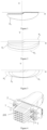
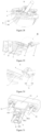
- a vehicle lamp module needs to be provided with a dimming mechanism to adjust a projected light shape of a lighting unit relative to a light shape at a standard position (the light shape is a light shape projected on a standard screen, and the standard screen for the high beam or the low beam of a headlamp is a vertical screen 25 m in front of a vehicle) or adjust projected light shapes of lighting units by an angle in an up-down or left-right direction, as shown in Figure 1 to Figure 3 , wherein P0 is the light shape at the standard position, P1, P2, P3 and P4 are light shapes at deviated positions, the light shape denoted by P1 needs downward dimming, the light shape denoted by P2 needs upward dimming, the light shape denoted by P3 needs rightward dimming, and the light shape denoted by P4 needs leftward dimming, to obtain the light shape
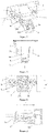
- a dimming mechanism used in a headlamp module at present includes three ball head screw assemblies 1, wherein each ball head screw assembly 1 includes a ball head screw 101 and a ball head nut 102, a shaft portion of the ball head screw 101 is provided with threads to achieve connection with a support frame or lamp body through the threads, and a front end of the ball head screw 101 is provided with a ball head which cooperates with the ball head nut 102 provided with a ball socket, and the ball head nut 102 is fixedly connected to a lighting unit 2.
- one ball head screw assembly 1 is provided as a fixed ball head screw assembly 1 relative to the support frame or lamp body, and the other two ball head screw assemblies 1 are provided as adjustable ball head screw assemblies 1 capable of moving forward and backward relative to the support frame or lamp body;
- one of the two adjustable ball head screw assemblies 1 is arranged below the fixed ball head screw assembly 1, and by rotating the ball head screw 101 of the adjustable ball head screw assembly 1, the ball head screw 101 moves forward and backward relative to the support frame or lamp body, causing the lighting unit 2 to rotate upward and downward relative to the support frame or lamp body about a horizontal dimming axis, to achieve dimming in the up-down direction;
- the other adjustable ball head screw assembly 1 is arranged on the left or right side of the fixed ball head screw assembly 1, and by rotating the ball head screw 101 of the adjustable ball head screw assembly 1, the ball head screw 101 moves forward and backward relative to the support frame or lamp body, causing the lighting unit 2 to rotate leftward and rightward relative to the support frame or lamp body about a vertical dimm
- the horizontal dimming axis is a horizontal axis formed by a connecting the center of a ball head of the adjustable ball head screw assembly 1 located on the left or right side of the fixed ball head screw assembly 1 and the center of a ball head of the fixed ball head screw assembly 1
- the vertical dimming axis is a vertical axis formed by a connecting the center of a ball head of the adjustable ball head screw assembly 1 located below the fixed ball head screw assembly 1 and the center of the ball head of the fixed ball head screw assembly 1.
- the adjustable ball head screw assembly 1 needs to be arranged on a side of or below the fixed ball head screw assembly 1, making an overall size a of the dimming mechanism in the up-down or left-right direction (as shown in Figure 7 ) larger, which is not adapted to the space layout requirement of the vehicle lamp module with an increasingly smaller size in the up-down or left-right direction; and second, if the size of the vehicle lamp module in the up-down or left-right direction is smaller, a distance L between two ball head screw assemblies 1 in the up-down direction or between two ball head screw assemblies 1 in the left-right direction is shorter, such that a moment arm for rotation is shorter, and a slight forward or backward movement of the adjustable ball head screw assembly 1 causes the lighting unit 2 to rotate a large angle, so that the dimming precision is lower.
- a technical problem to be solved by the present disclosure in a first aspect is to provide a dimming mechanism capable of implementing the miniaturization of the size of a vehicle lamp module in a second direction and improving the dimming precision in the second direction.
- a technical problem to be solved by the present disclosure in a second aspect is to provide a vehicle lamp module, a dimming mechanism of which is capable of implementing the miniaturization of the size of the vehicle lamp module in a second direction and improving the dimming precision in the second direction.
- a technical problem to be solved by the present disclosure in a third aspect is to provide a vehicle lamp, a dimming mechanism of which is capable of implementing the miniaturization of the size of a vehicle lamp module in a second direction and improving the dimming precision in the second direction.
- a technical problem to be solved by the present disclosure in a fourth aspect is to provide a vehicle, a dimming mechanism of which is capable of implementing the miniaturization of the size of a vehicle lamp module in a second direction and improving the dimming precision in the second direction.
- the present disclosure provides a dimming mechanism for dimming a lighting unit, which includes a fixed ball head connecting piece, a first adjustable ball head connecting piece and a second adjustable ball head connecting piece, wherein the fixed ball head connecting piece is connected to the lighting unit at one end and connected to a support frame or lamp body at the other end; the first adjustable ball head connecting piece is connected to the lighting unit at one end and is supported on the support frame or lamp body at the other end, and the first adjustable ball head connecting piece is capable of moving forward and backward relative to the support frame or lamp body to drive the lighting unit to rotate to achieve dimming in a first direction; and the lighting unit is provided with a sliding slot, and the second adjustable ball head connecting piece is slidably connected to the sliding slot, at one end and is supported on the support frame or lamp body at the other end, and the second adjustable ball head connecting piece is capable of moving forward and backward relative to the support frame or lamp body to drive the sliding slot to rotate and drive the lighting unit to rotate through the rotation of
- a connecting line between the center of a ball head of the fixed ball head connecting piece and the center of a ball head of the first adjustable ball head connecting piece extends in the first direction, and the second adjustable ball head connecting piece is arranged behind the fixed ball head connecting piece and the first adjustable ball head connecting piece.
- the first direction is an up-down direction
- the second direction is a left-right direction
- the center of the ball head of the fixed ball head connecting piece, the center of the ball head of the first adjustable ball head connecting piece and the center of a ball head of the second adjustable ball head connecting piece are placed in a same vertical plane.
- an included angle is formed between the sliding slot and the vertical plane.
- the first direction is a left-right direction
- the second direction is an up-down direction
- the center of the ball head of the fixed ball head connecting piece, the center of the ball head of the first adjustable ball head connecting piece and the center of the ball head of the second adjustable ball head connecting piece are placed in a same horizontal plane.
- an included angle is formed between the sliding slot and the horizontal plane.
- the fixed ball head connecting piece and the first adjustable ball head connecting piece are both ball head screw assemblies, and each of the ball head screw assemblies includes a ball head screw and a ball head nut.
- a sliding slot is formed in the lighting unit, and a slider is arranged on the sliding slot, and one end of the second adjustable ball head connecting piece is slidably connected to the sliding slot by means of the slider.
- the second adjustable ball head connecting piece is a ball head screw assembly
- the ball head screw assembly includes a ball head screw and a ball head nut
- the slider includes a slider base slidably connected to the sliding slot and a fixed part fixed on the slider base, the fixed part may be movably connected to the ball head of the second adjustable ball head connecting piece; or the slider is formed as a sliding bar connected to the ball head nut, and the slider may be slidably connected in the sliding slot.
- the fixed part is formed as an annular structure
- a clamping groove is formed in the second adjustable ball head connecting piece, the ball head nut of the second adjustable ball head connecting piece is clamped on the fixed part by means of the clamping groove, and the center of the ball head of the second adjustable ball head connecting piece is arranged on an axial center line of the annular structure; or a cylindrical slot is formed in the fixed part, the ball head of the second adjustable ball head connecting piece is mounted in the cylindrical slot in a matching manner and can slide along the cylindrical slot.
- an axial center line of the cylindrical slot is perpendicular to the vertical plane passing through the center of the ball head of the fixed ball head connecting piece and the center of the ball head of the second adjustable ball head connecting piece, wherein an inner surface of the cylindrical slot is formed by stretching an intersecting line between the ball head of the second adjustable ball head connecting piece and the vertical plane along the axial center line; or the axial center line of the cylindrical slot is formed as an arc segment with the center of the ball head of the fixed ball head connecting piece as a circle center and a connecting line between the center of the ball head of the fixed ball head connecting piece and the center of the ball head of the second adjustable ball head connecting piece as a radius, wherein the inner surface of the cylindrical slot is formed by stretching the intersecting line between the ball head of the second adjustable ball head connecting piece and the vertical plane along the axial center line, the vertical plane is a vertical plane passing through the center of the ball head of the fixed ball head connecting piece and the center of the ball head of the second adjustable ball head connecting piece.
- an elastic support structure is arranged on or integrally formed on one end surface, away from the fixed part, of the slider base, and the elastic support structure abuts against a bottom surface of the sliding slot and is capable of generating an opposite acting force to enable the slider base to fit tightly against the sliding slot and slide along the sliding slot.
- the elastic support structure is a pair of arc elastic sheets which extend in a direction of the sliding slot.
- the present disclosure provides a vehicle lamp module which includes the dimming mechanism according to any technical solution of the first aspect described above and a lighting unit.
- the lighting unit includes a heat sink, and a sliding slot is integrally or detachably formed in the heat sink.
- the present disclosure provides a vehicle lamp which includes the vehicle lamp module according to the technical solution of the second aspect described above.
- the present disclosure provides a vehicle which includes the vehicle lamp according to the technical solution of the third aspect described above.
- the forward and backward movement of the first adjustable ball head connecting piece causes the lighting unit to rotate to achieve dimming in the first direction
- the forward and backward movement of the second adjustable ball head connecting piece causes the sliding slot and the lighting unit to rotate to achieve dimming in the second direction.
- the second adjustable ball head connecting piece does not need to be arranged on a side of the fixed ball head connecting piece in the second direction, so that a size a' of the lighting unit in the second direction can be reduced, and the miniaturization of the lighting unit in the second direction is achieved.
- the dimming mechanism provided in the present disclosure achieves a slighter rotation of the lighting unit in the second direction, and thus has higher dimming precision in the second direction.
- connection and “link” should be interpreted in a broad sense unless otherwise clearly specified and defined.
- connection may be a fixed connection, a detachable connection, or an integral connection; it may be a direct connection, or an indirect connection through an intermediate medium, and it may also be a communication within two elements or an interaction relationship between two elements.
- link should be interpreted in a broad sense unless otherwise clearly specified and defined.
- it may be a fixed connection, a detachable connection, or an integral connection; it may be a direct connection, or an indirect connection through an intermediate medium, and it may also be a communication within two elements or an interaction relationship between two elements.
- front refers to a direction of a light emergent direction
- rear refers to a direction opposite to the “front”
- left refers to a left side in the light emergent direction
- right refers to a right side in the light emergent direction
- up refers to an upper side of the light emergent direction
- down refers to a lower side of the light emergent direction.
- a theoretical design state of a dimming mechanism is that the positional relationship between components of the dimming mechanism of the present disclosure is based on a lighting unit that does not require up-down and left-right dimming.
- the positional relationships between the components are designed based on a state when an optical axis of a lens 5 is parallel to a front-rear direction of a vehicle, including an included angle between a sliding slot 4 and a horizontal plane or a sliding slot 4 and a vertical plane, and the geometric relationship between an axial center line of a cylindrical slot 6021 and the centers of ball heads of two ball head screws 101, and after the vehicle lamp module is mounted on a vehicle lamp, the above positional relationships will change when dimming is performed due to manufacturing tolerances or assembly tolerances.
- the dimming mechanism is not only applicable to a lighting unit 2 with the lens 5, but also applicable to other lighting units, such as lighting units with reflective optical elements.
- a dimming mechanism for dimming a lighting unit 2, which includes a fixed ball head connecting piece 1a, a first adjustable ball head connecting piece 1b and a second adjustable ball head connecting piece 1c, wherein the fixed ball head connecting piece 1a is connected to the lighting unit 2 at one end and to a support frame or lamp body 3 at the other end; the first adjustable ball head connecting piece 1b is connected to the lighting unit 2 at one end and is supported on the support frame or lamp body 3 at the other end, and the first adjustable ball head connecting piece 1b is capable of moving forward and backward relative to the support frame or lamp body 3 to drive the lighting unit 2 to rotate to achieve dimming in a first direction; and the lighting unit 2 is provided with a sliding slot 4, and the second adjustable ball head connecting piece 1c is slidably connected to the sliding slot 4 at one end and is supported on the support frame or lamp body 3 at the other end, and the second adjustable ball head connecting piece 1
- first direction may be set to any direction, such as a left-right direction, an up-down direction or other directions; the second direction may also be set to any direction, but the first direction and the second direction need to be set to two different directions.
- first direction and the second direction are perpendicular to each other to achieve more accurate adjustment of the position of a light shape.
- An example in which the first direction and the second direction are perpendicular to each other is used below for further explanation and description.
- the first adjustable ball head connecting piece 1b and the second adjustable ball head connecting piece 1c may be ball head screw assemblies 1, or may also be rods with ball head structures.
- the fixed ball head connecting piece 1a may be any ball head connecting piece that can achieve fixed connection between the support frame or lamp body 3 and the lighting unit 2 and does not affect the rotation between the fixed ball head connecting piece 1a and the lighting unit 2, or may also be a ball head screw assembly 1 like the first adjustable ball head connecting piece 1b or the second adjustable ball head connecting piece 1c or a rod with a ball head structure.
- the ball head screw assembly 1 includes a ball head screw 101 and a ball head nut 102.
- the ball head screw 101 of the ball head screw assembly 1 is replaced with a rod that has no thread.
- the support frame or lamp body 3 is provided with two holes suitable for passage of the ball head screws 101 of the ball head screw assemblies 1, and the two holes are internally provided with internal threads adaptive to external threads of the ball head screws 101.
- the ball head screws 101 are rotated to cause the ball head screw assemblies 1 to move forward and backward, thereby driving the lighting unit 2 to rotate.
- the support frame or lamp body 3 is provided with two holes suitable for insertion of the rods of the first adjustable ball head connecting piece 1b and the second adjustable ball head connecting piece 1c, and the holes are set to a size that does not affect sliding of the first adjustable ball head connecting piece 1b or the second adjustable ball head connecting piece 1c inside the holes in the front-rear direction.
- the rods with the ball head structures are controlled to slide forward and backward, thereby driving the lighting unit 2 to rotate.
- first adjustable ball head connecting piece 1b and the second adjustable ball head connecting piece 1c may also be telescopic rods with ball head structures, that is, the ball head screws 101 of the ball head screw assemblies 1 are replaced with telescopic rods which can be fixedly connected to the support frame or lamp body 3, and the telescopic rods extend and retract to drive the lighting unit 2 to rotate.
- the first adjustable ball head connecting piece 1b and the second adjustable ball head connecting piece 1c are the ball head screw assemblies 1, and may be adjusted slightly to achieve higher precision.
- the sliding slot 4 is removably or integrally connected to the lighting unit 2.
- the sliding slot 4 is integrally connected to the lighting unit 2, so that installation steps of the vehicle lamp may be reduced.
- the ball head of the ball head screw 101 and the ball head nut 102 matched with the ball head in the fixed ball head connecting piece 1a form a revolving pair structure
- the ball head of the ball head screw 101 and the ball head nut 102 matched with the ball head in the fixed ball head connecting piece 1b form a revolving pair structure
- the forward and backward movement of the first adjustable ball head connecting piece 1b causes the lighting unit 2 to rotate about a first rotation axis I which is a straight line that passes through the center of the ball head of the fixed ball head connecting piece 1a and is perpendicular to the first direction, so that the light shape of the lighting unit 2 moves in the first direction, as shown in Figure 37 .
- the ball head of the ball head screw 101 and the ball head nut 102 matched with the ball head in the fixed ball head connecting piece 1a form a revolving pair structure
- the ball head of the ball head screw 101 and the ball head nut 102 matched with the ball head in the first adjustable ball head connecting piece 1b form a revolving pair structure
- the ball head of the ball head screw 101 and the ball head nut 102 matched with the ball head in the second adjustable ball head connecting piece 1c form a revolving pair structure
- the forward and backward movement of the second adjustable ball head connecting piece 1c causes the sliding slot 4 to rotate about a second rotation axis II which is a connecting line between the center of the ball head of the fixed ball head connecting piece 1a and the center of the ball head of the first adjustable ball head connecting piece 1b, thereby causing the lighting unit 2 to rotate, so that the light shape of the lighting unit 2 moves in the second direction, as shown in Figure 38 .
- the connecting line between the center of the ball head of the fixed ball head connecting piece 1a and the center of the ball head of the first adjustable ball head connecting piece 1b, i.e., the second rotation axis II, extends in the first direction
- the second adjustable ball head connecting piece 1c is arranged behind the fixed ball head connecting piece 1a and the first adjustable ball head connecting piece 1b, to be able to reduce a size a' of the lighting unit 2 in the second direction and increase a distance L' between the center of the ball head of the second adjustable ball head connecting piece 1c and the second rotation axis II, to achieve the miniaturization of the lighting unit 2 in the second direction and the dimming precision.
- the forward and backward movement of the first adjustable ball head connecting piece 1b drives the lighting unit 2 to rotate to achieve dimming in the first direction
- the forward and backward movement of the second adjustable ball head connecting piece 1c drives the sliding slot 4 and the lighting unit 2 to rotate to achieve dimming in the second direction.
- the second adjustable ball head connecting piece 1c does not need to be arranged on a side of the fixed ball head connecting piece 1a in the second direction, so that the size a' of the lighting unit 2 in the second direction can be reduced, and the miniaturization of the lighting unit 2 in the second direction is achieved.
- the distance L' between the center of the ball head of the second adjustable ball head connecting piece 1c and the second rotation axis II may be increased, that is, a moment arm for the lighting unit 2 rotating in the second direction is increased, as shown in Figure 12 , and compared with the prior art, for a same moving distance of the second adjustable ball head connecting piece 1c, the dimming mechanism provided in the present disclosure achieves slighter rotation of the lighting unit 2 in the second direction, and thus has higher dimming precision in the second direction.
- the first adjustable ball head connecting piece 1b is arranged at an end, away from the fixed ball head connecting piece 1a, of the lighting unit 2.
- a moment arm for the rotation of the lighting unit 2 during dimming in the first direction may be increased, so that the angle of rotation of the lighting unit 2 is smaller for a same moving distance of the first adjustable ball head connecting piece 1b, thus improving the dimming precision.
- the first direction is the up-down direction and the second direction is the left-right direction; and the center of the ball head of the fixed ball head connecting piece 1a, the center of the ball head of the first adjustable ball head connecting piece 1b and the center of the ball head of the second adjustable ball head connecting piece 1c are placed in the same vertical plane, which can reduce components generated in the left-right direction when dimming is performed in the up-down direction.
- the size of the lighting unit 2 in the left-right direction can be reduced and the miniaturization of the vehicle lamp module in the left-right direction can be achieved.
- the included angle formed between the sliding slot 4 and the above vertical plane may be 0°-90°, preferably 15°-60°.
- the included angle may be set specifically by those skilled in the art based on actual use and installation.
- the included angle between the sliding slot 4 and the vertical plane also refers to an included angle between the sliding slot 4 and the vertical plane in the theoretical design state, and when dimming is performed in the up-down and left-right directions, the sliding slot 4 swings, and the included angle also changes.
- the first direction is the left-right direction and the second direction is the up-down direction.
- the center of the ball head of the fixed ball head connecting piece 1a, the center of the ball head of the first adjustable ball head connecting piece 1b and the center of the ball head of the second adjustable ball head connecting piece 1c are placed in the same horizontal plane, which can reduce components generated in the up-down direction when dimming is performed in the left-right direction.
- the size of the lighting unit 2 in the up-down direction can be reduced and the miniaturization of the vehicle lamp module in the up-down direction can be achieved.
- the included angle formed between the sliding slot 4 and the above horizontal plane may be 0°-90°, preferably 15°-60°.
- the included angle may be set specifically by those skilled in the art based on actual use and installation.
- the included angle between the sliding slot 4 and the horizontal plane also refers to an included angle between the sliding slot 4 and the horizontal plane in the theoretical design state, and when dimming is performed in the up-down and left-right directions, the sliding slot 4 swings, and the included angle also changes.
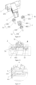
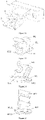
- the fixed ball head connecting piece 1a, the first adjustable ball head connecting piece 1b and the second adjustable ball head connecting piece 1c are ball head screw assemblies 1, and each of the ball head screw assemblies 1 includes a ball head screw 101 and a ball head nut 102; and a slider 6 that can be slidably connected to the sliding slot 4 is arranged on the sliding slot 4, and includes a slider base 601 slidably connected to the sliding slot 4 and a fixed part 602 fixed on the slider base 601, and the ball head nut 102 of the second adjustable ball head connecting piece 1c is connected to the fixed part 602 in a clamped manner.
- the fixed part 602 may be of an annular structure, and the ball head nut 102 of the second adjustable ball head connecting piece 1c is provided with a clamping groove, and the ball head nut 102 of the second adjustable ball head connecting piece 1c is clamped on the fixed part 602 by the clamping groove to prevent relative sliding of the second adjustable ball head connecting piece 1c on the fixed part 602, and the slider base 601 suitable for sliding in the sliding slot 4 is arranged on an outer side of the fixed part 602.
- the second adjustable ball head connecting piece 1c drives the fixed part 602 to move, thereby driving the slider 6 to move forward and backward and slide in the sliding slot 4.
- the sliding slot 4 is set obliquely relative to a plane where the center of the ball head of the fixed ball head connecting piece 1a, the center of the ball head of the first adjustable ball head connecting piece 1b and the center of the ball head of the second adjustable ball head connecting piece 1c are located, the forward and backward movement of the slider 6 causes the sliding slot 4 and the lighting unit 2 to rotate about the second rotation axis II which is the connecting line between the center of the ball head of the fixed ball head connecting piece 1a and the center of the ball head of the first adjustable ball head connecting piece 1b, thereby achieving dimming in the second direction.
- the lighting unit 2 rotates about the second rotation axis II, thereby achieving dimming in the left-right direction; and as shown in Figure 9 , when the second direction is the up-down direction, the lighting unit 2 rotates about the second rotation axis II, thereby achieving dimming in the up-down direction.
- the first adjustable ball head connecting piece 1b moves forward and backward relative to the support frame or lamp body 3, driving the lighting unit 2 to rotate in the first direction about the straight line that passes through the center of the ball head of the fixed ball head connecting piece 1a and is perpendicular to the first direction, to achieve dimming in the first direction.
- the lighting unit 2 rotates in the first direction relative to the support frame or lamp body 3, and as the sliding slot 4 is integrally formed in the lighting unit 2, and the second adjustable ball head connecting piece 1c and the slider 6 are fixed relative to the support frame or lamp body 3, the sliding slot 4 rotates in the first direction relative to the slider 6, and thus, there is a gap between the sliding slot 4 and the slider 6 in the first direction to enable the sliding slot 4 and the slider 6 to move relative to each other.
- the fixed ball head connecting piece 1a, the first adjustable ball head connecting piece 1b and the second adjustable ball head connecting piece 1c are ball head screw assemblies 1, and each of the ball head screw assemblies 1 includes a ball head screw 101 and a ball head nut 102; and a slider 6 is arranged on the ball head nut 102 of the second adjustable ball head connecting piece 1c, and is arranged in the sliding slot 4.
- the slider 6 is integrally arranged on the ball head nut 102.
- the sliding slot 4 here may be a gap that is formed by two rod-like structures, and suitable for clamping the slider 6, and an end, away from the ball head nut 102, of the slider 6 is provided with an opening which can make the slider 6 more elastic to facilitate better insertion of the slider 6 into the sliding slot 4, and enables the slider 6 to be better fixed in the sliding slot 4, so that the relative positions of the slider 6 and the sliding slot 4 are fixed when no dimming operation is performed to maintain the stability of the projected light shape of the lighting unit 2.
- the fixed ball head connecting piece 1a and the first adjustable ball head connecting piece 1b are ball head screw assemblies 1, and each of the ball head screw assemblies 1 includes a ball head screw 101 and a ball head nut 102; the second adjustable ball head connecting piece 1c is provided as a ball head screw 101; and a slider 6 that can be slidably connected to the sliding slot 4 is arranged on the sliding slot 4, and includes a slider base 601 slidably connected to the sliding slot 4 and a fixed part 602 fixed on the slider base 601, the fixed part 602 is provided with a cylindrical slot 6021 capable of cooperating with the ball head of the second adjustable ball head connecting piece 1c, and the ball head of the second adjustable ball head connecting piece 1c is capable of sliding relatively along the cylindrical
- the lighting unit 2 rotates in the first direction relative to the support frame or lamp body 3, and as the sliding slot 4 is integrally formed in the lighting unit 2, and the ball head of the second adjustable ball head connecting piece 1c is slidably connected to the slider 6 by the cylindrical slot 6021, and the second adjustable ball head connecting piece 1c is fixed relative to the support frame or lamp body 3, the slider 6 rotates together with the sliding slot 4 in the first direction, while the ball head of the second adjustable ball head connecting piece 1c does not move, thus the slider 6 cannot produce slight forward and backward movement or just produces extremely slight forward and backward movement relative to the sliding slot 4, reducing the slight rotation of the lighting unit 2 in the second direction.
- the second adjustable ball head connecting piece 1c is only slidably connected to the slider 6 through the cooperation of the ball head of the ball head screw 101 and the cylindrical slot 6021, the stress between parts is reduced.
- the center of the ball head of the second adjustable ball head connecting piece 1c is arranged on an axial center line 6022 of the cylindrical slot 6021.
- the second adjustable ball head connecting piece 1c drives the slider 6 to move forward and backward and slide in the sliding slot 4.
- the sliding slot 4 is set obliquely relative to a plane where the center of the ball head of the fixed ball head connecting piece 1a, the center of the ball head of the first adjustable ball head connecting piece 1b and the center of the ball head of the second adjustable ball head connecting piece 1c are located, so that the forward and backward movement of the slider 6 causes the sliding slot 4 and the lighting unit 2 to rotate about the second rotation axis II which is the connecting line between the center of the ball head of the fixed ball head connecting piece 1a and the center of the ball head of the first adjustable ball head connecting piece 1b, thereby achieving dimming in the second direction.
- the lighting unit 2 rotates about the second rotation axis II, thereby achieving dimming in the left-right direction; and when the second direction is the up-down direction, the lighting unit 2 rotates about the second rotation axis II, thereby achieving dimming in the up-down direction.
- the dimming mechanism includes a fixed ball head connecting piece 1a, a first adjustable ball head connecting piece 1b and a second adjustable ball head connecting piece 1c, wherein the first adjustable ball head connecting piece 1b and the fixed ball head connecting piece 1a are arranged at left and right ends of a lighting unit 2, and a connecting line between the centers of ball heads of the two connecting pieces is a horizontal line;
- the fixed ball head connecting piece 1a is connected to the lighting unit 2 at one end and connected to a support frame or lamp body 3 at the other end;
- the first adjustable ball head connecting piece 1b is connected to the lighting unit 2 at one end and is supported on the support frame or lamp body 3 at the other end, and the first adjustable ball head connecting piece 1b is capable of moving forward and backward relative to the support frame or lamp body 3;
- the lighting unit 2 is provided with a sliding slot 4, and a slider 6 that can be slidably connected to the sliding slot
- the first adjustable ball head connecting piece 1b, the second adjustable ball head connecting piece 1c and the fixed ball head connecting piece 1a are connected with the support frame or lamp body 3 by threads, and the support frame or lamp body 3 is used as a fixing component when dimming is performed.
- the first adjustable ball head connecting piece 1b moves forward and backward relative to the support frame or lamp body 3, driving the lighting unit 2 to rotate about the first rotation axis I, to achieve dimming in the left-right direction.
- the lighting unit 2 rotates to the left and right relative to the support frame or lamp body 3, and as the sliding slot 4 is integrally formed in the lighting unit 2, and the second adjustable ball head connecting piece 1c and the slider 6 are fixed relative to the support frame or lamp body 3, the sliding slot 4 rotates to the left and right relative to the slider 6, thus, there is a gap between the sliding slot 4 and the slider 6 in the left-right direction to enable the sliding slot 4 and the slider 6 to move relative to each other.
- the sliding slot 4 and the slider 6 cooperate in a bevel contact manner, when the sliding slot 4 may produce the left-right movement relative to the slider 6, movement in the up-down direction is also produced, and thus the lighting unit 2 also rotates slightly in the up-down direction.
- the second adjustable ball head connecting piece 1c moves forward and backward relative to the support frame or lamp body 3, and the slider 6 moves forward and backward in the sliding slot 4 inclined upward, such that the sliding slot 4 rotates about the second rotation axis II, driving the lighting unit 2 to rotate about the second rotation axis II, to achieve dimming in the up-down direction. If the second adjustable ball head connecting piece 1c moves forward, the lighting unit 2 rotates upward, and if the second adjustable ball head connecting piece 1c moves backward, the lighting unit 2 rotates downward.
- the dimming mechanism includes a fixed ball head connecting piece 1a, a first adjustable ball head connecting piece 1b and a second adjustable ball head connecting piece 1c, wherein the first adjustable ball head connecting piece 1b and the fixed ball head connecting piece 1a are arranged at left and right ends of a lighting unit 2, and a connecting line between the centers of ball heads of the two connecting pieces is a horizontal line;
- the fixed ball head connecting piece 1a is connected to the lighting unit 2 at one end and connected to a support frame or lamp body 3 at the other end;
- the first adjustable ball head connecting piece 1b is connected to the lighting unit 2 at one end and is supported on the support frame or lamp body 3 at the other end, and the first adjustable ball head connecting piece 1b is capable of moving forward and backward relative to the support frame or lamp body 3;
- the lighting unit 2 is provided with a sliding slot 4, and the fixed ball head connecting piece 1a, the first adjustable ball head connecting piece 1
- the dimming mechanism includes a fixed ball head connecting piece 1a, a first adjustable ball head connecting piece 1b and a second adjustable ball head connecting piece 1c, wherein the first adjustable ball head connecting piece 1b and the fixed ball head connecting piece 1a are arranged at left and right ends of the lighting unit 2, and a connecting line between the centers of ball heads of the two connecting pieces is a horizontal line;
- the fixed ball head connecting piece 1a is connected to the lighting unit 2 at one end and connected to a support frame or lamp body 3 at the other end;
- the first adjustable ball head connecting piece 1b is connected to the lighting unit 2 at one end and is supported on the support frame or lamp body 3 at the other end, and the first adjustable ball head connecting piece 1b is capable of moving forward and backward relative to the support frame or lamp body 3;
- the fixed ball head connecting piece 1a and the first adjustable ball head connecting piece 1b are both ball head screw assemblies 1, and each of the ball
- the second adjustable ball head connecting piece 1c is supported on the support frame or lamp body 3, and is capable of moving forward and backward relative to the support frame or lamp body 3; and the center of the ball head of the fixed ball head connecting piece 1a, the center of the ball head of the first adjustable ball head connecting piece 1b, and the center of the ball head of the second adjustable ball head connecting piece 1c are placed in a same horizontal plane, and an included angle is formed between the sliding slot 4 and the horizontal plane.
- the first adjustable ball head connecting piece 1b moves forward and backward relative to the support frame or lamp body 3, driving the lighting unit 2 to rotate about the first rotation axis I.
- the lighting unit 2 rotates to the left and right relative to the support frame or lamp body 3, to achieve dimming in the left-right direction.
- the second adjustable ball head connecting piece 1c moves forward and backward relative to the support frame or lamp body 3, and the slider 6 moves forward and backward in the sliding slot 4 inclined upward, such that the sliding slot 4 rotates about the second rotation axis II, driving the lighting unit 2 to rotate about the second rotation axis II, to achieve dimming in the up-down direction. If the second adjustable ball head connecting piece 1c moves forward, the lighting unit 2 rotates upward, and if the second adjustable ball head connecting piece 1c moves backward, the lighting unit 2 rotates downward.
- the forward and backward movement of the first adjustable ball head connecting piece 1b drives the lighting unit 2 to rotate to achieve dimming in the left-right direction
- the forward and backward movement of the second adjustable ball head connecting piece 1c drives the sliding slot 4 to rotate in the up-down direction to cause the lighting unit 2 to rotate in the up-down direction, thus achieving dimming in the up-down direction.
- the second adjustable ball head connecting piece 1c does not need to be arranged on a side of the fixed ball head connecting piece 1a in the up-down direction, so that the size a' of the lighting unit 2 in the up-down direction can be reduced, and the miniaturization of the vehicle lamp module in the up-down direction is achieved.
- the distance L' between the center of the ball head of the second adjustable ball head connecting piece 1c and the second rotation axis II may be increased, that is, a moment arm for the lighting unit 2 rotating in the up-down direction is increased, as shown in Figure 12 , and compared with the prior art, for a same moving distance of the second adjustable ball head connecting piece 1c, the dimming mechanism provided in the present disclosure achieves slighter rotation of the lighting unit 2 in the up-down direction, and thus the dimming precision in the up-down direction is higher.
- the distance between the center of the ball head of the first adjustable ball head connecting piece 1b and the first rotation axis I can be increased, that is, a moment arm for the lighting unit 2 rotating in the left-right direction is increased, and thus the dimming precision in the left-right direction is improved.
- the lighting unit 2 is provided with a sliding slot 4, and one end of the second adjustable ball head connecting piece 1c is slidably connected to the sliding slot 4 by a slider 6.
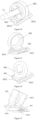
- the slider 6 includes a slider base 601 slidably connected to the sliding slot 4 and a fixed part 602 fixed on the slider base 601, and sliding parts 6011 are formed on two sides of the slider base 601, and the slider base 601 is slidably connected to the sliding slot 4 by the sliding parts 6011, so that the slider 6 can slide along the sliding slot 4.
- the sliding slot 4 has a guiding function, and the sliding parts 6011 on the two sides of the slider 6 are inserted into the sliding slot 4 such that the slider 6 can be guided to slide in the direction of the sliding slot 4.
- the slider 6 shown in Figures 19 to 25 , and 33 to 36 is provided with the fixed part 602 in two structural forms.
- the fixed part 602 can be movably connected to the ball head of the second adjustable ball head connecting piece 1c.
- the fixed part 602 is formed as an annular structure
- the second adjustable ball head connecting piece 1c includes a ball head screw 101 and a ball head nut 102
- a clamping groove is formed in the ball head nut 102, and can be clamped into the annular structure so that the fixed part 602 is connected with the second adjustable ball head connecting piece 1c in a clamped manner
- the center of the ball head of the second adjustable ball head connecting piece 1c is arranged on an axial center line 6022 of the annular structure.
- the fixed part 602 is formed in a circular shape, a clamping groove is formed in the ball head nut 102 of the second adjustable ball head connecting piece 1c, and can be clamped into the circular-shaped fixed part 602 to achieve fixed connection between the second adjustable ball head connecting piece 1c and the fixed part 602, and the fixed part 602 may be surrounded by an annular table, which can limit jaws for forming the clamping groove in the ball head nut 102 and also protect the clamping groove.
- the fixed part 602 is formed as a circular shape, but bosses 6023 are formed on two sides of the fixed part 602, and extend along an axial direction of the fixed part 602, and upper parts of the bosses 6023 on the two sides are formed as open structures.
- the fixed part 602 with the above two structures is selected as needed in actual installation.
- a cylindrical slot 6021 is formed in the fixed part 602
- the second adjustable ball head connecting piece 1c is provided as a ball head screw 101
- the ball head of the second adjustable ball head connecting piece 1c is mounted in the cylindrical slot 6021 in a matching manner and can slide along the cylindrical slot 6021.
- the center of the ball head of the second adjustable ball head connecting piece 1c is located on a vertical center plane of the slider 6, and vertical center planes of the slider 6, the sliding slot 4 and the lighting unit 2 coincide, and the axial center line 6022 of the cylindrical slot 6021 is perpendicular to a vertical plane passing through the center of the ball head of the fixed ball head connecting piece 1a and the center of the ball head of the second adjustable ball head connecting piece 1c, wherein the inner surface of the cylindrical slot 6021 is formed by stretching an intersecting line between the ball head of the second adjustable ball head connecting piece 1c and the vertical plane along the axial center line 6022.
- the slider 6 rotates along a track of an arc segment formed with the center of the ball head of the fixed ball head connecting piece 1a as a circle center and a connecting line between the center of the ball head of the fixed ball head connecting piece 1a and the center of the ball head of the second adjustable ball head connecting piece 1c as a radius, and the axial center line 6022 is a straight line
- the ball head of the second adjustable ball head connecting piece 1c can only slide along the straight line relative to the cylindrical slot 6021, and thus there is still a certain stress between the ball head of the second adjustable ball head connecting piece 1c and the cylindrical slot 6021; or the axial center line 6022 of the cylindrical slot 6021 is formed as an arc segment with the center of the ball head of the fixed ball head connecting piece 1a as a circle center and a connecting line between the center of the ball head of the fixed ball head connecting piece 1a and the center of the ball head of the second adjustable ball head connecting piece 1c as a radius, where
- the slider 6 rotates along the track of the above arc segment, and the relative sliding of the ball head of the second adjustable ball head connecting piece 1c and the cylindrical slot 6021 is also along the above arc segment, such that there is substantially no stress between the ball head of the second adjustable ball head connecting piece 1c and the cylindrical slot 6021, which is conducive to prolonging the service life of parts, but in consideration of the manufacturing cost of the parts and other reasons, a cylindrical slot 6021 whose axial center line 6022 is straight is preferred.
- the cylindrical slot 6021 is in tight fit with the ball head of the second adjustable ball head connecting piece 1c, which can not only ensure rotation of the ball head of the second adjustable ball head connecting piece 1c in the cylindrical slot 6021, but also ensure sliding of the ball head in the cylindrical slot 6021.
- an included angle is formed between a plane on the fixed part 602 attached to the clamping slot of the second adjustable ball head connecting piece 1c, and an upper or lower plane of the sliding parts 6011, and the sum of the included angle and the above included angle between the sliding slot 4 and the horizontal plane is 90°, which may also be understood as that an included angle is formed between the fixed part 602 and the slider base 601, and the sum of the included angle and the above included angle between the sliding slot 4 and the horizontal plane is 90°, to ensure that the second adjustable ball head connecting piece 1c extends horizontally.
- the slider 6 is formed as a sliding bar connected to the ball head nut 102, and the slider 6 can be slidably connected in the sliding slot 4.
- the structure of the sliding slot 4 may also be in the form of the structure shown in Figures 29 and 30 in addition to the structures shown in Figures 19 to 25 , and 33 to 36 , and at this time, the slider 6 slides in the sliding slot 4 and can also guide the second adjustable ball head connecting piece 1c to slide along the sliding slot 4.
- the cooperating structure of the slider 6 and the sliding slot 4 may also be in other structural forms, with the purpose of enabling the slider 6 to slide along the sliding slot 4, thereby enabling the second adjustable ball head connecting piece 1c to move forward and backward along the direction of the sliding slot 4, and the structural forms fall within the protection scope of the present disclosure.
- an elastic support structure 6012 is arranged on or integrally formed on one end surface, away from the fixed part 602, of the slider base 601, and the elastic support structure 6012 abuts against a bottom surface of the sliding slot 4 and is capable of generating an opposite acting force to enable the slider base 601 to be tightly attached to the sliding slot 4 and slide along the sliding slot 4.
- the elastic support structure 6012 is a pair of arc elastic sheets which extend in the direction of the sliding slot 4.
- one side edge of the elastic support structure 6012 is connected to a lower edge of the slider base 601. It may be understood that one side edge of the elastic support structure 6012 is connected to the lower edge of the slider base 601, and a gap is formed between the other side edge of the elastic support structure 6012 and the lower surface of the slider base 601, and meanwhile, the elastic support structure 6012 is of a curved structure bent downward.
- the sliding part 6011 is inserted into the sliding slot 4
- the sliding parts 6011 are tightly attached to the sliding slot 4 due to an elastic force of the elastic support structure 6012 without affecting the sliding of the sliding parts 6011 in the sliding slot 4.
- the terms “upper” and “lower” here only denote current positions of the parts shown in Figures 21 to 25 and 33 to 36 , and do not represent positions of the parts after actual installation.
- an embodiment of the present disclosure further provides a vehicle lamp module, which includes the dimming mechanism in any of the above embodiments and a lighting unit 2.
- the lighting unit 2 includes a heat sink 201, and a sliding slot 4 is integrally or detachably formed in the heat sink 201. Integral connection is preferred, which may reduce installation steps and reduce the difficulty of installation.
- an embodiment of the present disclosure provides a vehicle lamp, which includes the vehicle lamp module in any of the above embodiments.
- An embodiment of the present disclosure further provides a vehicle, which includes the vehicle lamp in the above embodiment.
Landscapes
- Engineering & Computer Science (AREA)
- General Engineering & Computer Science (AREA)
- Mechanical Engineering (AREA)
- Lighting Device Outwards From Vehicle And Optical Signal (AREA)
- Non-Portable Lighting Devices Or Systems Thereof (AREA)
- Fastening Of Light Sources Or Lamp Holders (AREA)
Applications Claiming Priority (2)
| Application Number | Priority Date | Filing Date | Title |
|---|---|---|---|
| CN202010456521.3A CN113719801B (zh) | 2020-05-26 | 2020-05-26 | 调光机构、车灯模组、车灯及车辆 |
| PCT/CN2020/111397 WO2021237961A1 (fr) | 2020-05-26 | 2020-08-26 | Mécanisme de gradation, module de phare de véhicule, phare de véhicule, et véhicule |
Publications (4)
| Publication Number | Publication Date |
|---|---|
| EP4137743A1 true EP4137743A1 (fr) | 2023-02-22 |
| EP4137743A4 EP4137743A4 (fr) | 2023-08-02 |
| EP4137743C0 EP4137743C0 (fr) | 2025-09-24 |
| EP4137743B1 EP4137743B1 (fr) | 2025-09-24 |
Family
ID=78745445
Family Applications (2)
| Application Number | Title | Priority Date | Filing Date |
|---|---|---|---|
| EP20937604.5A Active EP4137743B1 (fr) | 2020-05-26 | 2020-08-26 | Mécanisme de gradation, module de phare de véhicule, phare de véhicule, et véhicule |
| EP21814283.4A Active EP4123216B1 (fr) | 2020-05-26 | 2021-03-17 | Mécanisme de gradation, module de phare de véhicule, phare de véhicule et véhicule |
Family Applications After (1)
| Application Number | Title | Priority Date | Filing Date |
|---|---|---|---|
| EP21814283.4A Active EP4123216B1 (fr) | 2020-05-26 | 2021-03-17 | Mécanisme de gradation, module de phare de véhicule, phare de véhicule et véhicule |
Country Status (6)
| Country | Link |
|---|---|
| US (2) | US12097798B2 (fr) |
| EP (2) | EP4137743B1 (fr) |
| JP (2) | JP7442684B2 (fr) |
| KR (2) | KR102728010B1 (fr) |
| MX (1) | MX2021012521A (fr) |
| WO (1) | WO2021238352A1 (fr) |
Cited By (1)
| Publication number | Priority date | Publication date | Assignee | Title |
|---|---|---|---|---|
| EP4145043A4 (fr) * | 2021-02-26 | 2023-08-09 | Hasco Vision Technology Co., Ltd. | Mécanisme de régulation de lumière, module de feux de véhicule, feux de véhicule et véhicule |
Families Citing this family (3)
| Publication number | Priority date | Publication date | Assignee | Title |
|---|---|---|---|---|
| CN115507340B (zh) * | 2022-08-18 | 2024-08-20 | 江苏精新航空科技有限公司 | 一种具有自适应调光效果的汽车前照明装置 |
| CN116066784A (zh) * | 2023-03-06 | 2023-05-05 | 苏州耀腾光电有限公司 | 一种便于调节角度的汽车大灯 |
| CN116877949B (zh) * | 2023-07-14 | 2025-10-10 | 常州星宇车灯股份有限公司 | 调光支架及其调节方法 |
Family Cites Families (32)
| Publication number | Priority date | Publication date | Assignee | Title |
|---|---|---|---|---|
| US4884174A (en) | 1988-05-06 | 1989-11-28 | Valeo Vision | Attachment and hinging component, especially for a device to adjust an optical element, particularly for a motor vehicle headlight |
| AT2305U1 (de) * | 1997-05-14 | 1998-08-25 | Zizala Lichtsysteme Gmbh | Kfz-scheinwerferverstellung |
| JP3938631B2 (ja) * | 1998-05-25 | 2007-06-27 | 株式会社小糸製作所 | 車両用灯具 |
| JP2001151011A (ja) | 1999-11-22 | 2001-06-05 | Stanley Electric Co Ltd | 自動車用灯具のエイミング調整装置 |
| JP3883356B2 (ja) | 2000-03-14 | 2007-02-21 | 株式会社小糸製作所 | リフレクター可動型自動車用ヘッドランプ |
| CZ294405B6 (cs) | 2000-05-23 | 2004-12-15 | Autopal, S. R. O. | Světlomet pro vozidla |
| JP3718124B2 (ja) * | 2000-12-28 | 2005-11-16 | 株式会社小糸製作所 | リフレクター可動型自動車用ヘッドランプ |
| JP3888672B2 (ja) | 2001-12-25 | 2007-03-07 | 株式会社小糸製作所 | リフレクター可動型自動車用ヘッドランプ |
| JP5460447B2 (ja) | 2010-04-26 | 2014-04-02 | 株式会社小糸製作所 | 車両用灯具のエイミング装置 |
| JP2012156018A (ja) * | 2011-01-26 | 2012-08-16 | Ichikoh Ind Ltd | 車両用前照灯 |
| FR2978393B1 (fr) | 2011-07-26 | 2014-11-21 | Valeo Vision | Ensemble d'un support de module optique et d'un dispositif de liaison apte a recevoir un moyen de reglage de la position du support |
| KR101358588B1 (ko) | 2013-01-30 | 2014-02-05 | 희성전자 주식회사 | 부재 간의 각도를 조절할 수 있는 연결 장치 |
| DE112015002486B4 (de) * | 2014-05-26 | 2020-01-09 | Shanghai Koito Automotive Lamp Co., Ltd | Verstellvorrichtung für die Abblend- bzw. Fernlichtform eines Fahrzeugscheinwerfers |
| DE102015110553A1 (de) * | 2015-07-01 | 2017-01-05 | Hella Kgaa Hueck & Co. | Scheinwerfer für ein Kraftfahrzeug |
| CN108302487B (zh) | 2016-09-22 | 2024-06-25 | 常州星宇车灯股份有限公司 | 车用前照灯远近光调光装置 |
| JP6798254B2 (ja) | 2016-11-02 | 2020-12-09 | 市光工業株式会社 | 軸受機構及び自動車用のヘッドランプ |
| US10960808B2 (en) * | 2016-12-16 | 2021-03-30 | Foshan Ichikoh Valeo Auto Lighting Systems Co., Ltd. | Regulating assembly for light source, and lighting and/or signaling device, adjusting device, lighting device and motor vehicle, bezel device, gas guiding device, and lighting and/or signaling device containing the same |
| DE102017115001A1 (de) | 2017-07-05 | 2019-01-10 | Automotive Lighting Reutlingen Gmbh | Justierbares Scheinwerfersystem |
| US10690295B2 (en) * | 2017-07-12 | 2020-06-23 | Global Navigation Sciences, Inc. | Apparatus with computer interface module for use in vehicles |
| JP6991429B2 (ja) | 2017-09-25 | 2022-01-12 | カワサキモータース株式会社 | 鞍乗型車両のヘッドランプ装置 |
| EP3470267A1 (fr) | 2017-10-13 | 2019-04-17 | Valeo Iluminacion | Lampe d'automobile à amortissement de vibrations amélioré |
| EP3505396B1 (fr) * | 2017-12-27 | 2020-04-08 | ZKW Group GmbH | Zone de pivotement centrale |
| CN108626675A (zh) * | 2018-02-08 | 2018-10-09 | 常州星宇车灯股份有限公司 | 一种汽车前雾灯调光机构 |
| GB201803809D0 (en) * | 2018-03-09 | 2018-04-25 | Bee Lighting Ltd | Apparatus for angular adjustment of lighting unit components |
| CN208997981U (zh) | 2018-09-13 | 2019-06-18 | 浙江零跑科技有限公司 | 一种汽车车灯的调光装置 |
| CN208983248U (zh) | 2018-11-20 | 2019-06-14 | 南京海琦娜游艇制造有限公司 | 一种可调节任意角度的救生艇搜救灯 |
| CN110006001A (zh) | 2019-04-16 | 2019-07-12 | 广州小鹏汽车科技有限公司 | 车灯和车辆 |
| CN209688728U (zh) | 2019-05-13 | 2019-11-26 | 上汽大众汽车有限公司 | 调光系统 |
| CN210267077U (zh) | 2019-06-26 | 2020-04-07 | 常州星宇车灯股份有限公司 | 一种汽车前灯模组调节结构 |
| CN112303586B (zh) * | 2019-07-31 | 2025-04-08 | 华域视觉科技(上海)有限公司 | 车辆照明装置、车辆大灯及车辆 |
| CN210050735U (zh) | 2019-07-31 | 2020-02-11 | 华域视觉科技(上海)有限公司 | 调光机构、车灯及车辆 |
| CN212673117U (zh) | 2020-05-26 | 2021-03-09 | 华域视觉科技(上海)有限公司 | 调光机构、车灯模组、车灯及车辆 |
-
2020
- 2020-08-26 JP JP2022570698A patent/JP7442684B2/ja active Active
- 2020-08-26 KR KR1020227039162A patent/KR102728010B1/ko active Active
- 2020-08-26 US US17/926,326 patent/US12097798B2/en active Active
- 2020-08-26 MX MX2021012521A patent/MX2021012521A/es unknown
- 2020-08-26 EP EP20937604.5A patent/EP4137743B1/fr active Active
-
2021
- 2021-03-17 JP JP2022563338A patent/JP7556981B2/ja active Active
- 2021-03-17 EP EP21814283.4A patent/EP4123216B1/fr active Active
- 2021-03-17 KR KR1020227039436A patent/KR102762365B1/ko active Active
- 2021-03-17 WO PCT/CN2021/081312 patent/WO2021238352A1/fr not_active Ceased
- 2021-03-17 US US17/919,629 patent/US11970107B2/en active Active
Cited By (1)
| Publication number | Priority date | Publication date | Assignee | Title |
|---|---|---|---|---|
| EP4145043A4 (fr) * | 2021-02-26 | 2023-08-09 | Hasco Vision Technology Co., Ltd. | Mécanisme de régulation de lumière, module de feux de véhicule, feux de véhicule et véhicule |
Also Published As
| Publication number | Publication date |
|---|---|
| EP4123216C0 (fr) | 2024-07-10 |
| EP4123216A1 (fr) | 2023-01-25 |
| EP4137743A4 (fr) | 2023-08-02 |
| EP4123216A4 (fr) | 2023-08-02 |
| EP4137743C0 (fr) | 2025-09-24 |
| US12097798B2 (en) | 2024-09-24 |
| MX2021012521A (es) | 2022-01-24 |
| JP2023522089A (ja) | 2023-05-26 |
| US20230194061A1 (en) | 2023-06-22 |
| US11970107B2 (en) | 2024-04-30 |
| US20230150419A1 (en) | 2023-05-18 |
| KR102762365B1 (ko) | 2025-02-03 |
| JP7556981B2 (ja) | 2024-09-26 |
| KR102728010B1 (ko) | 2024-11-07 |
| KR20220167307A (ko) | 2022-12-20 |
| KR20220166863A (ko) | 2022-12-19 |
| JP7442684B2 (ja) | 2024-03-04 |
| JP2023527522A (ja) | 2023-06-29 |
| WO2021238352A1 (fr) | 2021-12-02 |
| EP4123216B1 (fr) | 2024-07-10 |
| EP4137743B1 (fr) | 2025-09-24 |
Similar Documents
| Publication | Publication Date | Title |
|---|---|---|
| EP4137743B1 (fr) | Mécanisme de gradation, module de phare de véhicule, phare de véhicule, et véhicule | |
| JP3599727B2 (ja) | スポットライト | |
| KR20230100723A (ko) | 조정기구 및 그 내부 적색점 조준 | |
| CN212673117U (zh) | 调光机构、车灯模组、车灯及车辆 | |
| CN117182409B (zh) | 一种虚拟成像系统计算机零件焊接装置 | |
| WO2021237961A1 (fr) | Mécanisme de gradation, module de phare de véhicule, phare de véhicule, et véhicule | |
| CN215723022U (zh) | 一种灯具调焦装置及灯具 | |
| US7758194B2 (en) | Light source adjusting device | |
| EP4145043B1 (fr) | Module de feux de véhicule avec mécanisme de réglage, feux de véhicule et véhicule | |
| CN114043573B (zh) | 一种遮光片内孔两面的全倒角模具 | |
| CN212901298U (zh) | 一种舞台灯具效果组件的伸缩结构 | |
| CN117968035A (zh) | 光学调节结构、光学模组、车灯及车辆 | |
| CN223090499U (zh) | 一种调焦装置及照明设备 | |
| CN213513297U (zh) | 一种灯的变焦机构 | |
| CN209801260U (zh) | 一种用于摇头灯的变焦装置 | |
| CN219684299U (zh) | 一种具有高效散热结构的激光点焊机 | |
| CN222068349U (zh) | 一种多层调焦结构 | |
| CN224042817U (zh) | 一种co2扫描切割头 | |
| CN219806471U (zh) | 一种双向可调式振镜模组 | |
| CN218523457U (zh) | 一种追光灯用的调焦组件 | |
| CN224122822U (zh) | 一种导轨式调焦装置 | |
| CN205200797U (zh) | 激光镜片调整装置及应用激光镜片调整装置的激光机设备 | |
| CN223258030U (zh) | 光学集成装置及灯具 | |
| CN220296123U (zh) | 一种激光焊接装置 | |
| CN222269014U (zh) | 一种自动调节对焦装置及激光雕刻机 |
Legal Events
| Date | Code | Title | Description |
|---|---|---|---|
| STAA | Information on the status of an ep patent application or granted ep patent |
Free format text: STATUS: THE INTERNATIONAL PUBLICATION HAS BEEN MADE |
|
| PUAI | Public reference made under article 153(3) epc to a published international application that has entered the european phase |
Free format text: ORIGINAL CODE: 0009012 |
|
| STAA | Information on the status of an ep patent application or granted ep patent |
Free format text: STATUS: REQUEST FOR EXAMINATION WAS MADE |
|
| 17P | Request for examination filed |
Effective date: 20221117 |
|
| AK | Designated contracting states |
Kind code of ref document: A1 Designated state(s): AL AT BE BG CH CY CZ DE DK EE ES FI FR GB GR HR HU IE IS IT LI LT LU LV MC MK MT NL NO PL PT RO RS SE SI SK SM TR |
|
| A4 | Supplementary search report drawn up and despatched |
Effective date: 20230630 |
|
| RIC1 | Information provided on ipc code assigned before grant |
Ipc: F21W 102/155 20180101ALI20230626BHEP Ipc: F21W 107/10 20180101ALI20230626BHEP Ipc: B60Q 1/068 20060101ALI20230626BHEP Ipc: F21S 41/657 20180101ALI20230626BHEP Ipc: F21S 41/19 20180101AFI20230626BHEP |
|
| DAV | Request for validation of the european patent (deleted) | ||
| DAX | Request for extension of the european patent (deleted) | ||
| GRAP | Despatch of communication of intention to grant a patent |
Free format text: ORIGINAL CODE: EPIDOSNIGR1 |
|
| STAA | Information on the status of an ep patent application or granted ep patent |
Free format text: STATUS: GRANT OF PATENT IS INTENDED |
|
| INTG | Intention to grant announced |
Effective date: 20250509 |
|
| GRAS | Grant fee paid |
Free format text: ORIGINAL CODE: EPIDOSNIGR3 |
|
| GRAA | (expected) grant |
Free format text: ORIGINAL CODE: 0009210 |
|
| STAA | Information on the status of an ep patent application or granted ep patent |
Free format text: STATUS: THE PATENT HAS BEEN GRANTED |
|
| AK | Designated contracting states |
Kind code of ref document: B1 Designated state(s): AL AT BE BG CH CY CZ DE DK EE ES FI FR GB GR HR HU IE IS IT LI LT LU LV MC MK MT NL NO PL PT RO RS SE SI SK SM TR |
|
| REG | Reference to a national code |
Ref country code: GB Ref legal event code: FG4D |
|
| REG | Reference to a national code |
Ref country code: CH Ref legal event code: EP |
|
| REG | Reference to a national code |
Ref country code: IE Ref legal event code: FG4D |
|
| U01 | Request for unitary effect filed |
Effective date: 20250924 |
|
| U07 | Unitary effect registered |
Designated state(s): AT BE BG DE DK EE FI FR IT LT LU LV MT NL PT RO SE SI Effective date: 20250930 |
|
| PG25 | Lapsed in a contracting state [announced via postgrant information from national office to epo] |
Ref country code: NO Free format text: LAPSE BECAUSE OF FAILURE TO SUBMIT A TRANSLATION OF THE DESCRIPTION OR TO PAY THE FEE WITHIN THE PRESCRIBED TIME-LIMIT Effective date: 20251224 |
|
| PG25 | Lapsed in a contracting state [announced via postgrant information from national office to epo] |
Ref country code: HR Free format text: LAPSE BECAUSE OF FAILURE TO SUBMIT A TRANSLATION OF THE DESCRIPTION OR TO PAY THE FEE WITHIN THE PRESCRIBED TIME-LIMIT Effective date: 20250924 |
|
| PG25 | Lapsed in a contracting state [announced via postgrant information from national office to epo] |
Ref country code: GR Free format text: LAPSE BECAUSE OF FAILURE TO SUBMIT A TRANSLATION OF THE DESCRIPTION OR TO PAY THE FEE WITHIN THE PRESCRIBED TIME-LIMIT Effective date: 20251225 |
|
| PG25 | Lapsed in a contracting state [announced via postgrant information from national office to epo] |
Ref country code: RS Free format text: LAPSE BECAUSE OF FAILURE TO SUBMIT A TRANSLATION OF THE DESCRIPTION OR TO PAY THE FEE WITHIN THE PRESCRIBED TIME-LIMIT Effective date: 20251224 |
|
| PG25 | Lapsed in a contracting state [announced via postgrant information from national office to epo] |
Ref country code: SM Free format text: LAPSE BECAUSE OF FAILURE TO SUBMIT A TRANSLATION OF THE DESCRIPTION OR TO PAY THE FEE WITHIN THE PRESCRIBED TIME-LIMIT Effective date: 20250924 |
|
| PG25 | Lapsed in a contracting state [announced via postgrant information from national office to epo] |
Ref country code: ES Free format text: LAPSE BECAUSE OF FAILURE TO SUBMIT A TRANSLATION OF THE DESCRIPTION OR TO PAY THE FEE WITHIN THE PRESCRIBED TIME-LIMIT Effective date: 20250924 |
|
| PG25 | Lapsed in a contracting state [announced via postgrant information from national office to epo] |
Ref country code: IS Free format text: LAPSE BECAUSE OF FAILURE TO SUBMIT A TRANSLATION OF THE DESCRIPTION OR TO PAY THE FEE WITHIN THE PRESCRIBED TIME-LIMIT Effective date: 20260124 |
|
| PG25 | Lapsed in a contracting state [announced via postgrant information from national office to epo] |
Ref country code: CZ Free format text: LAPSE BECAUSE OF FAILURE TO SUBMIT A TRANSLATION OF THE DESCRIPTION OR TO PAY THE FEE WITHIN THE PRESCRIBED TIME-LIMIT Effective date: 20250924 |
|
| PG25 | Lapsed in a contracting state [announced via postgrant information from national office to epo] |
Ref country code: PL Free format text: LAPSE BECAUSE OF FAILURE TO SUBMIT A TRANSLATION OF THE DESCRIPTION OR TO PAY THE FEE WITHIN THE PRESCRIBED TIME-LIMIT Effective date: 20250924 |
|
| PG25 | Lapsed in a contracting state [announced via postgrant information from national office to epo] |
Ref country code: SK Free format text: LAPSE BECAUSE OF FAILURE TO SUBMIT A TRANSLATION OF THE DESCRIPTION OR TO PAY THE FEE WITHIN THE PRESCRIBED TIME-LIMIT Effective date: 20250924 |