EP4137747A1 - Fuel injectors with heat exchangers - Google Patents
Fuel injectors with heat exchangers Download PDFInfo
- Publication number
- EP4137747A1 EP4137747A1 EP22191156.3A EP22191156A EP4137747A1 EP 4137747 A1 EP4137747 A1 EP 4137747A1 EP 22191156 A EP22191156 A EP 22191156A EP 4137747 A1 EP4137747 A1 EP 4137747A1
- Authority
- EP
- European Patent Office
- Prior art keywords
- fuel
- air
- channel
- air channel
- heat exchanger
- Prior art date
- Legal status (The legal status is an assumption and is not a legal conclusion. Google has not performed a legal analysis and makes no representation as to the accuracy of the status listed.)
- Granted
Links
Images



Classifications
-
- F—MECHANICAL ENGINEERING; LIGHTING; HEATING; WEAPONS; BLASTING
- F02—COMBUSTION ENGINES; HOT-GAS OR COMBUSTION-PRODUCT ENGINE PLANTS
- F02C—GAS-TURBINE PLANTS; AIR INTAKES FOR JET-PROPULSION PLANTS; CONTROLLING FUEL SUPPLY IN AIR-BREATHING JET-PROPULSION PLANTS
- F02C7/00—Features, components parts, details or accessories, not provided for in, or of interest apart form groups F02C1/00 - F02C6/00; Air intakes for jet-propulsion plants
- F02C7/12—Cooling of plants
- F02C7/14—Cooling of plants of fluids in the plant, e.g. lubricant or fuel
- F02C7/141—Cooling of plants of fluids in the plant, e.g. lubricant or fuel of working fluid
-
- F—MECHANICAL ENGINEERING; LIGHTING; HEATING; WEAPONS; BLASTING
- F23—COMBUSTION APPARATUS; COMBUSTION PROCESSES
- F23R—GENERATING COMBUSTION PRODUCTS OF HIGH PRESSURE OR HIGH VELOCITY, e.g. GAS-TURBINE COMBUSTION CHAMBERS
- F23R3/00—Continuous combustion chambers using liquid or gaseous fuel
- F23R3/28—Continuous combustion chambers using liquid or gaseous fuel characterised by the fuel supply
- F23R3/283—Attaching or cooling of fuel injecting means including supports for fuel injectors, stems, or lances
-
- F—MECHANICAL ENGINEERING; LIGHTING; HEATING; WEAPONS; BLASTING
- F02—COMBUSTION ENGINES; HOT-GAS OR COMBUSTION-PRODUCT ENGINE PLANTS
- F02C—GAS-TURBINE PLANTS; AIR INTAKES FOR JET-PROPULSION PLANTS; CONTROLLING FUEL SUPPLY IN AIR-BREATHING JET-PROPULSION PLANTS
- F02C7/00—Features, components parts, details or accessories, not provided for in, or of interest apart form groups F02C1/00 - F02C6/00; Air intakes for jet-propulsion plants
- F02C7/12—Cooling of plants
- F02C7/16—Cooling of plants characterised by cooling medium
-
- F—MECHANICAL ENGINEERING; LIGHTING; HEATING; WEAPONS; BLASTING
- F02—COMBUSTION ENGINES; HOT-GAS OR COMBUSTION-PRODUCT ENGINE PLANTS
- F02C—GAS-TURBINE PLANTS; AIR INTAKES FOR JET-PROPULSION PLANTS; CONTROLLING FUEL SUPPLY IN AIR-BREATHING JET-PROPULSION PLANTS
- F02C7/00—Features, components parts, details or accessories, not provided for in, or of interest apart form groups F02C1/00 - F02C6/00; Air intakes for jet-propulsion plants
- F02C7/22—Fuel supply systems
- F02C7/224—Heating fuel before feeding to the burner
-
- F—MECHANICAL ENGINEERING; LIGHTING; HEATING; WEAPONS; BLASTING
- F02—COMBUSTION ENGINES; HOT-GAS OR COMBUSTION-PRODUCT ENGINE PLANTS
- F02C—GAS-TURBINE PLANTS; AIR INTAKES FOR JET-PROPULSION PLANTS; CONTROLLING FUEL SUPPLY IN AIR-BREATHING JET-PROPULSION PLANTS
- F02C7/00—Features, components parts, details or accessories, not provided for in, or of interest apart form groups F02C1/00 - F02C6/00; Air intakes for jet-propulsion plants
- F02C7/26—Starting; Ignition
- F02C7/264—Ignition
-
- F—MECHANICAL ENGINEERING; LIGHTING; HEATING; WEAPONS; BLASTING
- F28—HEAT EXCHANGE IN GENERAL
- F28D—HEAT-EXCHANGE APPARATUS, NOT PROVIDED FOR IN ANOTHER SUBCLASS, IN WHICH THE HEAT-EXCHANGE MEDIA DO NOT COME INTO DIRECT CONTACT
- F28D7/00—Heat-exchange apparatus having stationary tubular conduit assemblies for both heat-exchange media, the media being in contact with different sides of a conduit wall
- F28D7/02—Heat-exchange apparatus having stationary tubular conduit assemblies for both heat-exchange media, the media being in contact with different sides of a conduit wall the conduits being helically coiled
- F28D7/022—Heat-exchange apparatus having stationary tubular conduit assemblies for both heat-exchange media, the media being in contact with different sides of a conduit wall the conduits being helically coiled the conduits of two or more media in heat-exchange relationship being helically coiled, the coils having a cylindrical configuration
-
- F—MECHANICAL ENGINEERING; LIGHTING; HEATING; WEAPONS; BLASTING
- F05—INDEXING SCHEMES RELATING TO ENGINES OR PUMPS IN VARIOUS SUBCLASSES OF CLASSES F01-F04
- F05D—INDEXING SCHEME FOR ASPECTS RELATING TO NON-POSITIVE-DISPLACEMENT MACHINES OR ENGINES, GAS-TURBINES OR JET-PROPULSION PLANTS
- F05D2220/00—Application
- F05D2220/30—Application in turbines
- F05D2220/32—Application in turbines in gas turbines
- F05D2220/323—Application in turbines in gas turbines for aircraft propulsion, e.g. jet engines
-
- F—MECHANICAL ENGINEERING; LIGHTING; HEATING; WEAPONS; BLASTING
- F05—INDEXING SCHEMES RELATING TO ENGINES OR PUMPS IN VARIOUS SUBCLASSES OF CLASSES F01-F04
- F05D—INDEXING SCHEME FOR ASPECTS RELATING TO NON-POSITIVE-DISPLACEMENT MACHINES OR ENGINES, GAS-TURBINES OR JET-PROPULSION PLANTS
- F05D2240/00—Components
- F05D2240/35—Combustors or associated equipment
-
- F—MECHANICAL ENGINEERING; LIGHTING; HEATING; WEAPONS; BLASTING
- F05—INDEXING SCHEMES RELATING TO ENGINES OR PUMPS IN VARIOUS SUBCLASSES OF CLASSES F01-F04
- F05D—INDEXING SCHEME FOR ASPECTS RELATING TO NON-POSITIVE-DISPLACEMENT MACHINES OR ENGINES, GAS-TURBINES OR JET-PROPULSION PLANTS
- F05D2260/00—Function
- F05D2260/20—Heat transfer, e.g. cooling
- F05D2260/213—Heat transfer, e.g. cooling by the provision of a heat exchanger within the cooling circuit
-
- F—MECHANICAL ENGINEERING; LIGHTING; HEATING; WEAPONS; BLASTING
- F05—INDEXING SCHEMES RELATING TO ENGINES OR PUMPS IN VARIOUS SUBCLASSES OF CLASSES F01-F04
- F05D—INDEXING SCHEME FOR ASPECTS RELATING TO NON-POSITIVE-DISPLACEMENT MACHINES OR ENGINES, GAS-TURBINES OR JET-PROPULSION PLANTS
- F05D2260/00—Function
- F05D2260/20—Heat transfer, e.g. cooling
- F05D2260/232—Heat transfer, e.g. cooling characterized by the cooling medium
-
- F—MECHANICAL ENGINEERING; LIGHTING; HEATING; WEAPONS; BLASTING
- F05—INDEXING SCHEMES RELATING TO ENGINES OR PUMPS IN VARIOUS SUBCLASSES OF CLASSES F01-F04
- F05D—INDEXING SCHEME FOR ASPECTS RELATING TO NON-POSITIVE-DISPLACEMENT MACHINES OR ENGINES, GAS-TURBINES OR JET-PROPULSION PLANTS
- F05D2260/00—Function
- F05D2260/30—Retaining components in desired mutual position
-
- F—MECHANICAL ENGINEERING; LIGHTING; HEATING; WEAPONS; BLASTING
- F05—INDEXING SCHEMES RELATING TO ENGINES OR PUMPS IN VARIOUS SUBCLASSES OF CLASSES F01-F04
- F05D—INDEXING SCHEME FOR ASPECTS RELATING TO NON-POSITIVE-DISPLACEMENT MACHINES OR ENGINES, GAS-TURBINES OR JET-PROPULSION PLANTS
- F05D2260/00—Function
- F05D2260/99—Ignition, e.g. ignition by warming up of fuel or oxidizer in a resonant acoustic cavity
-
- F—MECHANICAL ENGINEERING; LIGHTING; HEATING; WEAPONS; BLASTING
- F28—HEAT EXCHANGE IN GENERAL
- F28D—HEAT-EXCHANGE APPARATUS, NOT PROVIDED FOR IN ANOTHER SUBCLASS, IN WHICH THE HEAT-EXCHANGE MEDIA DO NOT COME INTO DIRECT CONTACT
- F28D1/00—Heat-exchange apparatus having stationary conduit assemblies for one heat-exchange medium only, the media being in contact with different sides of the conduit wall, in which the other heat-exchange medium is a large body of fluid, e.g. domestic or motor car radiators
- F28D1/06—Heat-exchange apparatus having stationary conduit assemblies for one heat-exchange medium only, the media being in contact with different sides of the conduit wall, in which the other heat-exchange medium is a large body of fluid, e.g. domestic or motor car radiators with the heat-exchange conduits forming part of, or being attached to, the tank containing the body of fluid
-
- Y—GENERAL TAGGING OF NEW TECHNOLOGICAL DEVELOPMENTS; GENERAL TAGGING OF CROSS-SECTIONAL TECHNOLOGIES SPANNING OVER SEVERAL SECTIONS OF THE IPC; TECHNICAL SUBJECTS COVERED BY FORMER USPC CROSS-REFERENCE ART COLLECTIONS [XRACs] AND DIGESTS
- Y02—TECHNOLOGIES OR APPLICATIONS FOR MITIGATION OR ADAPTATION AGAINST CLIMATE CHANGE
- Y02T—CLIMATE CHANGE MITIGATION TECHNOLOGIES RELATED TO TRANSPORTATION
- Y02T50/00—Aeronautics or air transport
- Y02T50/60—Efficient propulsion technologies, e.g. for aircraft
Definitions
- the present disclosure relates generally to fuel and air systems for gas turbine engines, and more particularly to fuel injectors for gas turbine engines.
- a portion of the compressor discharge air in a gas turbine engine can be diverted from the main gas flow though the engine for various uses in the engine and onboard an aircraft.
- this air is typically too hot to be of use in general applications.
- Fuel air heat exchangers can be used to cool the diverted portion of compressed air.
- fuel air heat exchangers are not typically easy to retrofit on existing engine designs and this among other things leaves a need in the art for improved systems and methods for fuel air heat exchange. This disclosure provides a solution for this need.
- a fuel injector system for a gas turbine engine includes a mounting flange configured to be mounted to an engine case.
- a fixture extends in an outward direction from the mounting flange operable to connect to fuel and air systems outside the engine case.
- a feed arm extends radially inward from the mounting flange.
- a fuel nozzle extends from the feed arm and is operable to issue fuel into a combustor.
- a fuel channel extends from an inlet, through the feed arm, and out an outlet of the fuel nozzle.
- An air channel extends from an inlet in the feed arm and/or nozzle, through the feed arm, and to an outlet in the fixture.
- the fuel channel and the air channel are in fluid isolation from one another to maintain separation of fuel and air.
- the fuel channel and the air channel are in thermal communication with one another as a heat exchanger to cool air in the air channel and heat fuel in the fuel channel.
- the heat exchanger can be a counter flow heat exchanger.
- the inlet of the air channel can be in the feed arm between the fuel nozzle and the mounting flange.
- the fuel channel can include a tube extending from the mounting flange to the fuel nozzle, and the air channel can be defined in an annular space between an outer envelope of the feed arm and the tube.
- the tube can include a coiled section of the tube configured to provide residence time for fuel passing through the heat exchanger.
- the flange can be mounted to an engine case, and the feed arm can include a heat exchanger section.
- the coiled section can be in the heat exchanger section, and the heat exchanger section can extend inward from the mounting flange into the engine case.
- the nozzle can be mounted proximate to and in fluid communication through a combustor dome wall to issue fuel into a space on a combustor side of the combustor dome wall.
- the inlet of the air channel can be in a position to receive compressor discharge air from a compressor side of the combustor dome wall opposite the space on the combustor side of the combustor dome wall.
- the inlet of the air channel can be in the fuel nozzle.
- the fuel channel and air channel can be in intimate thermal contact through a heat exchanger wall for a majority of the fuel nozzle with respect to axial length of the fuel nozzle.
- the inlet of the air channel can be in an axial end of the fuel nozzle, and the outlet of the fuel channel can be in the axial end of the fuel nozzle.
- the inlet of the air channel can be on a radially outward facing portion of the fuel nozzle.
- the inlet of the air channel can be on a radially inward facing portion of the fuel nozzle.
- the fuel channel and the air channel can be in intimate thermal communication with one another through a heat exchanger wall in the feed arm.
- the flange can be mounted to an engine case, wherein the feed arm includes a heat exchanger section.
- At least one of the feed arm and fuel nozzle can include a coiled section of the fuel and/or air channels that is in the heat exchanger section, wherein the heat exchanger section extends within the engine case. There need be no o-rings sealing directly between the air channel and the engine case.
- a method of producing compressed air for use onboard an aircraft includes receiving compressor discharge air into an air channel of a fuel injector. The method also includes cooling the compressor discharge air within the air channel by heat exchange with fuel flowing in the fuel injector, and issuing cooled air from the internal air channel out of an engine case as a source of compressed air. The method can include reversing direction of airflow in the air channel to provide air assist for ignition of fuel flowing in the fuel injector.
- Fig. 1 a partial view of an embodiment of a fuel injector in accordance with the disclosure is shown in Fig. 1 and is designated generally by reference character 100.
- FIGs. 2-5 Other embodiments of systems in accordance with the disclosure, or aspects thereof, are provided in Figs. 2-5 , as will be described.
- the systems and methods described herein can be used to provide fuel nozzles with integrated fuel air heat exchangers readily retrofittable into existing engines as well as new engines.
- the system includes a fuel injector 100 for a gas turbine engine 10, which includes a mounting flange 102 mounted to the engine case 104.
- a fixture 106 extends in an outward direction from the mounting flange 104 operable to connect to fuel and air systems outside the engine case 104.
- a feed arm 108 extends radially inward from the mounting flange 104.
- a fuel nozzle 110 extends from the feed arm 108 and is operable to issue fuel into a combustor 112.
- a fuel channel 114 extends from an inlet 116, through the feed arm 108, and out an outlet 118 of the fuel nozzle 110.
- An air channel 120 extends from an inlet 122 in the feed arm 108, through the feed arm 108, and to an outlet 124 in the fixture 106.
- the fuel channel 114 and the air channel 120 are in fluid isolation from one another to maintain separation of fuel and air.
- the fuel channel 114 and the air channel 120 are in thermal communication with one another as a heat exchanger 126 to cool air in the air channel 120 and to heat, e.g. pre-heat, fuel in the fuel channel 114.
- the heat exchanger 126 is a counter flow heat exchanger.
- the inlet 122 of the air channel 120 is in the feed arm 108 between the fuel nozzle 110 and the mounting flange 102, and closer to the fuel nozzle 110 than to the flange 102.
- the fuel channel 114 includes a tube 128 extending from the mounting flange 102 to the fuel nozzle 110.
- the air channel 120 is defined in an annular space 130 between an outer envelope 132 of the feed arm 108 and the tube 128.
- the inlet 122 is an opening through the outer envelope 132.
- the tube 128 serves as a heat exchanger wall through which heat is conducted from the hot air to the cool fuel.
- the single tube 128 shown is a simple heat exchanger. However it is contemplated that more elaborate heat exchangers can be used in the same location to increase the shared conductive wall in order to enhance heat transfer without departing from the scope of this disclosure.
- the tube 128 keeps the fuel and air in thermal communication with one another, and in fluid isolation from one another.
- the tube 128 and other components of the fuel injector 100 can be assembled using brazing, welding, additive manufacturing, and/or any other suitable techniques.
- the tube 128 includes a coiled section of the tube 128 configured to provide residence time for fuel passing through the heat exchanger 126.
- the feed arm 108 includes a heat exchanger section 134, and the coiled section of the tube 128 is in the heat exchanger section 134.
- the heat exchanger section 134 extends inward from the mounting flange 104 into the engine case 104. There need be no o-rings sealing for air directly between the air channel 120 in the heat exchanger section 134 and the engine case 104, however there can be o-rings sealing fuel in the fuel channel 114 as needed. Similarly, there need be no o-rings sealing directly between the fuel channel 114 in the heat exchanger section 134 and the engine case 104.
- the nozzle 110 is mounted proximate to and in fluid communication through the combustor dome wall 136 to issue fuel into a space on a combustor side of the combustor dome wall 136 as indicated by the diverging spray arrows in Fig. 2 .
- the inlet 122 of the air channel 120 is in a position to receive compressor discharge air from a compressor side (the compressor diffuser 138 is labeled in Fig. 1 ) of the combustor dome wall 136 opposite the combustor space on the combustor side of the combustor dome wall 136.
- Other inlet locations for the air channel 120 are also contemplated, as described below with reference to Figs. 3-5 .
- FIG. 3 another embodiment of a fuel injector 100 is shown with a different heat exchanger inlet and configuration from that shown in Figs. 1-2 .
- the inlet 122 of the air channel 120 is in the fuel nozzle 110 in this case.
- the fuel channel 114 and air channel 120 are in intimate thermal contact through a heat exchanger wall 128 (labeled in Fig. 4 ) for a majority of the fuel nozzle 110 with respect to axial length L of the fuel nozzle 110.
- the inlet 122 of the air channel 120 is in an axial end 140 of the fuel nozzle 110.
- the outlet 118 of the fuel channel 114 is in the axial end 140 of the fuel nozzle 110 as well.
- Fig. 4 another embodiment of a fuel injector 100 is shown with a different heat exchanger inlet and configuration from that shown in Figs. 1-2 .
- the inlet 122 of the air channel 120 is in the fuel nozzle 110 in this case.
- the fuel channel 114 and air channel 120 are in intimate thermal contact through
- the inlet 122 of the air channel 120 is shown, along with two other possible inlet locations.
- the fuel channel 114 and the air channel 120 are in intimate thermal communication with one another through a heat exchanger wall 128 in the feed arm 108 (as shown in Fig. 3 ), in addition to the thermal contact through the fuel distributor portion of the fuel nozzle 110 (as shown in Figs. 4-5 ).
- a fuel injector can be a heat exchanger section in its substantial entirety, for example, all the way from the inlet flange 102 to the nozzle exit tip 118.
- the feed arm 208 is just a straight member with straight channels, but could be helical as well similar to the fuel nozzle 110 to allow for increased heat transfer.
- the feed arm 108 can be coiled like a coiled tube to allow for thermal compliance.
- the flange 102 is mounted to an engine case 104.
- At least one of the feed arm 108 and fuel nozzle 110 include a coiled section (e.g., as shown in Fig.4 ) of the fuel and/or air channels 114, 120 that is in the heat exchanger section, wherein the heat exchanger section extends within the engine case 104.
- a coiled section e.g., as shown in Fig.4
- the heat exchanger section extends within the engine case 104.
- Figs. 3-5 there need be no o-rings sealing directly between the engine case 104 and either of the air channel 120 or the fuel channel 114. Instead, fuel and air communicate through the engine case 104 through the fixture 106.
- Figs. 4-5 can be made by additive manufacturing, for example.
- a method of producing compressed air includes receiving compressor discharge air into an air channel, e.g. air channel 120, of a fuel injector, e.g. fuel injector 100.
- the method also includes cooling the compressor discharge air within the air channel by heat exchange with fuel flowing in the fuel injector, and issuing cooled air from the internal air channel out of an engine case, e.g. engine case 104, as a source of compressed air.
- the method can include reversing direction of airflow in the air channel to provide air assist for ignition of fuel flowing in the fuel injector.
- Potential benefits include a high pressure, cooled air stream available for cooling other parts of the engine or airplane.
Landscapes
- Engineering & Computer Science (AREA)
- Chemical & Material Sciences (AREA)
- Combustion & Propulsion (AREA)
- Mechanical Engineering (AREA)
- General Engineering & Computer Science (AREA)
- Physics & Mathematics (AREA)
- Thermal Sciences (AREA)
- Fuel-Injection Apparatus (AREA)
Abstract
Description
- The present disclosure relates generally to fuel and air systems for gas turbine engines, and more particularly to fuel injectors for gas turbine engines.
- A portion of the compressor discharge air in a gas turbine engine can be diverted from the main gas flow though the engine for various uses in the engine and onboard an aircraft. However, this air is typically too hot to be of use in general applications. Fuel air heat exchangers can be used to cool the diverted portion of compressed air. However, fuel air heat exchangers are not typically easy to retrofit on existing engine designs and this among other things leaves a need in the art for improved systems and methods for fuel air heat exchange. This disclosure provides a solution for this need.
- A fuel injector system for a gas turbine engine includes a mounting flange configured to be mounted to an engine case. A fixture extends in an outward direction from the mounting flange operable to connect to fuel and air systems outside the engine case. A feed arm extends radially inward from the mounting flange. A fuel nozzle extends from the feed arm and is operable to issue fuel into a combustor. A fuel channel extends from an inlet, through the feed arm, and out an outlet of the fuel nozzle. An air channel extends from an inlet in the feed arm and/or nozzle, through the feed arm, and to an outlet in the fixture. The fuel channel and the air channel are in fluid isolation from one another to maintain separation of fuel and air. The fuel channel and the air channel are in thermal communication with one another as a heat exchanger to cool air in the air channel and heat fuel in the fuel channel.
- The heat exchanger can be a counter flow heat exchanger. The inlet of the air channel can be in the feed arm between the fuel nozzle and the mounting flange. The fuel channel can include a tube extending from the mounting flange to the fuel nozzle, and the air channel can be defined in an annular space between an outer envelope of the feed arm and the tube.
- The tube can include a coiled section of the tube configured to provide residence time for fuel passing through the heat exchanger. The flange can be mounted to an engine case, and the feed arm can include a heat exchanger section. The coiled section can be in the heat exchanger section, and the heat exchanger section can extend inward from the mounting flange into the engine case. There need be no o-rings sealing directly between the air channel in the heat exchanger section and the engine case, and there need be no o-rings sealing directly between the fuel channel in the heat exchanger section and the engine case.
- The nozzle can be mounted proximate to and in fluid communication through a combustor dome wall to issue fuel into a space on a combustor side of the combustor dome wall. The inlet of the air channel can be in a position to receive compressor discharge air from a compressor side of the combustor dome wall opposite the space on the combustor side of the combustor dome wall.
- It is also contemplated that the inlet of the air channel can be in the fuel nozzle. The fuel channel and air channel can be in intimate thermal contact through a heat exchanger wall for a majority of the fuel nozzle with respect to axial length of the fuel nozzle. The inlet of the air channel can be in an axial end of the fuel nozzle, and the outlet of the fuel channel can be in the axial end of the fuel nozzle. The inlet of the air channel can be on a radially outward facing portion of the fuel nozzle. The inlet of the air channel can be on a radially inward facing portion of the fuel nozzle.
- The fuel channel and the air channel can be in intimate thermal communication with one another through a heat exchanger wall in the feed arm. The flange can be mounted to an engine case, wherein the feed arm includes a heat exchanger section. At least one of the feed arm and fuel nozzle can include a coiled section of the fuel and/or air channels that is in the heat exchanger section, wherein the heat exchanger section extends within the engine case. There need be no o-rings sealing directly between the air channel and the engine case.
- A method of producing compressed air for use onboard an aircraft includes receiving compressor discharge air into an air channel of a fuel injector. The method also includes cooling the compressor discharge air within the air channel by heat exchange with fuel flowing in the fuel injector, and issuing cooled air from the internal air channel out of an engine case as a source of compressed air. The method can include reversing direction of airflow in the air channel to provide air assist for ignition of fuel flowing in the fuel injector.
- These and other features of the systems and methods of the subject disclosure will become more readily apparent to those skilled in the art from the following detailed description of the preferred embodiments taken in conjunction with the drawings.
- So that those skilled in the art to which the subject disclosure appertains will readily understand how to make and use the devices and methods of the subject disclosure without undue experimentation, preferred embodiments thereof will be described in detail herein below with reference to certain figures, wherein:
-
Fig. 1 is a schematic cross-sectional view of an embodiment of a system constructed in accordance with the present disclosure, showing a fuel injector with an integrated fuel air heat exchanger extending into the engine case; -
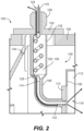
Fig. 2 is a schematic cross-sectional view of the fuel injector ofFig. 1 , showing the air and fuel channels of the fuel air heat exchanger; -
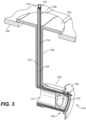
Fig. 3 is a schematic cross-sectional perspective view of another exemplary embodiment of a fuel injector, showing an integrated fuel air heat exchanger with an air inlet in the fuel nozzle; -
Fig. 4 is a schematic perspective view of a portion of the fuel injector ofFig. 3 , schematically showing the counter flowing air channel and fuel distributor channels; and -
Fig. 5 is a schematic cross-sectional side elevation view of a portion of the fuel nozzle ofFig. 3 , showing air channel inlet locations. - Reference will now be made to the drawings wherein like reference numerals identify similar structural features or aspects of the subject disclosure. For purposes of explanation and illustration, and not limitation, a partial view of an embodiment of a fuel injector in accordance with the disclosure is shown in
Fig. 1 and is designated generally byreference character 100. Other embodiments of systems in accordance with the disclosure, or aspects thereof, are provided inFigs. 2-5 , as will be described. The systems and methods described herein can be used to provide fuel nozzles with integrated fuel air heat exchangers readily retrofittable into existing engines as well as new engines. - The system includes a
fuel injector 100 for agas turbine engine 10, which includes amounting flange 102 mounted to theengine case 104. Afixture 106 extends in an outward direction from themounting flange 104 operable to connect to fuel and air systems outside theengine case 104. Afeed arm 108 extends radially inward from themounting flange 104. Afuel nozzle 110 extends from thefeed arm 108 and is operable to issue fuel into acombustor 112. Afuel channel 114 extends from aninlet 116, through thefeed arm 108, and out anoutlet 118 of thefuel nozzle 110. Anair channel 120 extends from aninlet 122 in thefeed arm 108, through thefeed arm 108, and to anoutlet 124 in thefixture 106. Thefuel channel 114 and theair channel 120 are in fluid isolation from one another to maintain separation of fuel and air. Thefuel channel 114 and theair channel 120 are in thermal communication with one another as aheat exchanger 126 to cool air in theair channel 120 and to heat, e.g. pre-heat, fuel in thefuel channel 114. - With reference now to
Fig. 2 , and as indicated by the flow arrows, theheat exchanger 126 is a counter flow heat exchanger. Theinlet 122 of theair channel 120 is in thefeed arm 108 between thefuel nozzle 110 and themounting flange 102, and closer to thefuel nozzle 110 than to theflange 102. Thefuel channel 114 includes atube 128 extending from themounting flange 102 to thefuel nozzle 110. Theair channel 120 is defined in an annular space 130 between anouter envelope 132 of thefeed arm 108 and thetube 128. Theinlet 122 is an opening through theouter envelope 132. Thetube 128 serves as a heat exchanger wall through which heat is conducted from the hot air to the cool fuel. Thesingle tube 128 shown is a simple heat exchanger. However it is contemplated that more elaborate heat exchangers can be used in the same location to increase the shared conductive wall in order to enhance heat transfer without departing from the scope of this disclosure. Thetube 128 keeps the fuel and air in thermal communication with one another, and in fluid isolation from one another. Thetube 128 and other components of thefuel injector 100 can be assembled using brazing, welding, additive manufacturing, and/or any other suitable techniques. - The
tube 128 includes a coiled section of thetube 128 configured to provide residence time for fuel passing through theheat exchanger 126. Thefeed arm 108 includes aheat exchanger section 134, and the coiled section of thetube 128 is in theheat exchanger section 134. Theheat exchanger section 134 extends inward from the mountingflange 104 into theengine case 104. There need be no o-rings sealing for air directly between theair channel 120 in theheat exchanger section 134 and theengine case 104, however there can be o-rings sealing fuel in thefuel channel 114 as needed. Similarly, there need be no o-rings sealing directly between thefuel channel 114 in theheat exchanger section 134 and theengine case 104. It is therefore a relatively straightforward retrofit of an existing engine or engine design, which involves little more than replacement of conventional fuel injectors with afuel injector 100, to provide a supply of cool, useful compressed air outside theengine case 104. Theoutlet 124 of theair channel 120 simply needs to be connected to an air system ready to receive the compressed air. - With continued reference to
Fig. 2 , thenozzle 110 is mounted proximate to and in fluid communication through thecombustor dome wall 136 to issue fuel into a space on a combustor side of thecombustor dome wall 136 as indicated by the diverging spray arrows inFig. 2 . Theinlet 122 of theair channel 120 is in a position to receive compressor discharge air from a compressor side (thecompressor diffuser 138 is labeled inFig. 1 ) of thecombustor dome wall 136 opposite the combustor space on the combustor side of thecombustor dome wall 136. Other inlet locations for theair channel 120 are also contemplated, as described below with reference toFigs. 3-5 . - With reference now to
Fig. 3 , another embodiment of afuel injector 100 is shown with a different heat exchanger inlet and configuration from that shown inFigs. 1-2 . Theinlet 122 of theair channel 120 is in thefuel nozzle 110 in this case. Thefuel channel 114 andair channel 120 are in intimate thermal contact through a heat exchanger wall 128 (labeled inFig. 4 ) for a majority of thefuel nozzle 110 with respect to axial length L of thefuel nozzle 110. Theinlet 122 of theair channel 120 is in anaxial end 140 of thefuel nozzle 110. Theoutlet 118 of thefuel channel 114 is in theaxial end 140 of thefuel nozzle 110 as well. InFig. 5 , theinlet 122 of theair channel 120 is shown, along with two other possible inlet locations. First, is aninlet 142 on a radially outward facing portion of thefuel nozzle 110 in fluid communication with aninsulation gap 146. Another is aninlet 144 on a radially inward facing portion of thefuel nozzle 110. - The
fuel channel 114 and theair channel 120 are in intimate thermal communication with one another through aheat exchanger wall 128 in the feed arm 108 (as shown inFig. 3 ), in addition to the thermal contact through the fuel distributor portion of the fuel nozzle 110 (as shown inFigs. 4-5 ). It is also contemplated that a fuel injector can be a heat exchanger section in its substantial entirety, for example, all the way from theinlet flange 102 to thenozzle exit tip 118. As shown inFig 3 , the feed arm 208 is just a straight member with straight channels, but could be helical as well similar to thefuel nozzle 110 to allow for increased heat transfer. Also, thefeed arm 108 can be coiled like a coiled tube to allow for thermal compliance. Theflange 102 is mounted to anengine case 104. At least one of thefeed arm 108 andfuel nozzle 110 include a coiled section (e.g., as shown inFig.4 ) of the fuel and/orair channels engine case 104. As withFig. 1 , inFigs. 3-5 there need be no o-rings sealing directly between theengine case 104 and either of theair channel 120 or thefuel channel 114. Instead, fuel and air communicate through theengine case 104 through thefixture 106. Depending on the specific nozzle configuration, some locations are better to prevent fuel from entering into the air circuit. For example, if air was directly taken in the same area where fuel is injected, some fuel might be taken into the air cavity, which would be better to avoid. The structure shown inFigs. 4-5 can be made by additive manufacturing, for example. - A method of producing compressed air, e.g. for use onboard an aircraft, includes receiving compressor discharge air into an air channel,
e.g. air channel 120, of a fuel injector,e.g. fuel injector 100. The method also includes cooling the compressor discharge air within the air channel by heat exchange with fuel flowing in the fuel injector, and issuing cooled air from the internal air channel out of an engine case, e.g.engine case 104, as a source of compressed air. The method can include reversing direction of airflow in the air channel to provide air assist for ignition of fuel flowing in the fuel injector. - Potential benefits include a high pressure, cooled air stream available for cooling other parts of the engine or airplane. There are strong safety factors achieved by locating the fuel air heat exchanger inside of the engine case. As the fuel is not heated until it is within the fuel injector feed arm cavity, elastomeric seals can still be used to connect the fuel manifold to the fuel injector without melting the seals. Velocities of the fuel are also at the highest in the fuel injector, which allows for more heat transfer than slow moving fuel locations. Heat exchange is also in a counter-flow direction (inlet of fuel and inlet of air are at opposite sides of the heat exchanger), which enhances heat transfer. In reverse operation, there can be compressed air added through the fuel injector which acts both as cooling air if needed, as well as an air assist to provide additional fuel atomization, for example at engine startup or altitude relight. Fuel can continue to heat exchange with air all the way up the feed arm. Larger or smaller air and fuel circuits can be used to tailor heat transfer rates. Temperature sensors can be integral to the fuel distributer tip and air flow rates controlled with a valve to prevent overheating the fuel temperatures.
- The methods and systems of the present disclosure, as described above and shown in the drawings, provide for fuel nozzles with integrated fuel air heat exchangers readily retrofittable into existing engines as well as new engines. While the apparatus and methods of the subject disclosure have been shown and described with reference to preferred embodiments, those skilled in the art will readily appreciate that changes and/or modifications may be made thereto without departing from the scope of the invention as defined by the claims.
Claims (15)
- A fuel injector system for a gas turbine engine comprising:a mounting flange (102) configured to be mounted to an engine case (104);a fixture (106) extending in an outward direction from the mounting flange operable to connect to fuel and air systems outside the engine case;a feed arm (108) extending radially inward from the mounting flange;a fuel nozzle (110) extending from the feed arm and operable to issue fuel into a combustor (112);a fuel channel (114) extending from an inlet (116), through the feed arm, and out an outlet (118) of the fuel nozzle; andan air channel (120) extending from an inlet in the feed arm and/or nozzle, through the feed arm, and to an outlet in the fixture, wherein the fuel channel and the air channel are in fluid isolation from one another, and wherein the fuel channel and the air channel are in thermal communication with one another as a heat exchanger.
- The system as recited in claim 1, wherein the heat exchanger is a counter flow heat exchanger.
- The system as recited in claim 1 or 2, wherein the inlet (122) of the air channel is in the feed arm between the fuel nozzle and the mounting flange.
- The system as recited in claim 3, wherein the fuel channel includes a tube (128) extending from the mounting flange to the fuel nozzle, and wherein the air channel is defined in an annular space (130) between an outer envelope (132) of the feed arm and the tube.
- The system as recited in claim 4, wherein the tube includes a coiled section of the tube.
- The system as recited in claim 5, wherein the flange is mounted to an engine case (104), wherein the feed arm includes a heat exchanger section (134), wherein the coiled section is in the heat exchanger section, and wherein the heat exchanger section extends inward from the mounting flange into the engine case.
- The system as recited in claim 6, wherein there are no o-rings sealing directly between the air channel in the heat exchanger section and the engine case, or wherein there are no o-rings sealing directly between the fuel channel in the heat exchanger section and the engine case.
- The system as recited in claim 3, further comprising a combustor dome wall (136), wherein the nozzle is mounted proximate to and in fluid communication through the combustor dome wall to issue fuel into a space on a combustor side of the combustor dome wall, wherein the inlet of the air channel is in a position to receive compressor discharge air from a compressor side of the combustor dome wall opposite the space on the combustor side of the combustor dome wall.
- The system as recited in any preceding claim, wherein the inlet of the air channel is in the fuel nozzle.
- The system as recited in claim 9, wherein the fuel channel and air channel are in intimate thermal contact through a heat exchanger wall for a portion of the fuel nozzle with respect to axial length of the fuel nozzle.
- The system as recited in claim 10, wherein the inlet of the air channel is in an axial end of the fuel nozzle, and wherein the outlet of the fuel channel is in the axial end of the fuel nozzle, or wherein the inlet of the air channel is on a radially outward facing portion of the fuel nozzle, or wherein the inlet of the air channel is on a radially inward facing portion of the fuel nozzle.
- The system as recited in claim 10, wherein the fuel channel and the air channel are in intimate thermal contact with one another through a heat exchanger wall in the feed arm.
- The system as recited in claim 9, wherein the flange is mounted to an engine case, wherein the feed arm includes a heat exchanger section, wherein at least one of the feed arm and fuel nozzle include a coiled section of the fuel and/or air channels that is in the heat exchanger section, and wherein the heat exchanger section extends within the engine case, and optionally wherein there are no o-rings sealing directly between the air channel and the engine case.
- A method of producing compressed air for use onboard an aircraft comprising:receiving compressor discharge air into an air channel of a fuel injector;cooling the compressor discharge air within the air channel by heat exchange with fuel flowing in the fuel injector; andissuing cooled air from the internal air channel out of an engine case as a source of compressed air.
- The method as recited in claim 18, further comprising reversing direction of airflow in the air channel to provide air assist for ignition of fuel flowing in the fuel injector.
Applications Claiming Priority (1)
| Application Number | Priority Date | Filing Date | Title |
|---|---|---|---|
| US17/406,657 US11555450B1 (en) | 2021-08-19 | 2021-08-19 | Fuel injectors with heat exchangers |
Publications (2)
| Publication Number | Publication Date |
|---|---|
| EP4137747A1 true EP4137747A1 (en) | 2023-02-22 |
| EP4137747B1 EP4137747B1 (en) | 2024-05-29 |
Family
ID=83004842
Family Applications (1)
| Application Number | Title | Priority Date | Filing Date |
|---|---|---|---|
| EP22191156.3A Active EP4137747B1 (en) | 2021-08-19 | 2022-08-19 | Fuel injectors with heat exchangers |
Country Status (2)
| Country | Link |
|---|---|
| US (1) | US11555450B1 (en) |
| EP (1) | EP4137747B1 (en) |
Families Citing this family (6)
| Publication number | Priority date | Publication date | Assignee | Title |
|---|---|---|---|---|
| US11952946B2 (en) * | 2021-10-15 | 2024-04-09 | Rtx Corporation | Turbine engine with preheat of cryogenic fuel via intermediate fluid |
| JP7729413B2 (en) * | 2022-02-08 | 2025-08-26 | 株式会社Ihi | Injection nozzle and combustion device |
| US12209750B2 (en) * | 2023-02-14 | 2025-01-28 | Collins Engine Nozzles, Inc. | Line replaceable fuel injector panels with single hatch installation |
| US20250283432A1 (en) * | 2024-03-08 | 2025-09-11 | General Electric Company | Fuel injector cooling system |
| US12497922B1 (en) * | 2024-09-03 | 2025-12-16 | Collins Engine Nozzles, Inc. | Fuel preheating for fuel injection |
| US12529337B1 (en) * | 2024-11-18 | 2026-01-20 | Rtx Corporation | Additively manufactured turbine engine case with fuel manifold |
Citations (5)
| Publication number | Priority date | Publication date | Assignee | Title |
|---|---|---|---|---|
| US20100071667A1 (en) * | 2008-09-19 | 2010-03-25 | Woodward Governor Company | Active Thermal Protection For Fuel Injectors |
| US20160290290A1 (en) * | 2015-03-30 | 2016-10-06 | Honeywell International Inc. | Gas turbine engine fuel cooled cooling air heat exchanger |
| US20190338735A1 (en) * | 2015-03-31 | 2019-11-07 | Delavan Inc | Fuel nozzles |
| US20200018234A1 (en) * | 2014-05-09 | 2020-01-16 | United Technologies Corporation | Cooled fuel injector system for a gas turbine engine and a method for operating the same |
| US20200217510A1 (en) * | 2019-01-03 | 2020-07-09 | General Electric Company | Heat Exchanger for Turbo Machine |
Family Cites Families (13)
| Publication number | Priority date | Publication date | Assignee | Title |
|---|---|---|---|---|
| US3472025A (en) | 1967-08-28 | 1969-10-14 | Parker Hannifin Corp | Nozzle and manifold assembly |
| US5211003A (en) * | 1992-02-05 | 1993-05-18 | General Electric Company | Diffuser clean air bleed assembly |
| EP0741850B1 (en) * | 1994-01-24 | 1998-05-27 | Siemens Aktiengesellschaft | Method of burning fuel in compressed air |
| US8943827B2 (en) | 2011-05-31 | 2015-02-03 | Pratt & Whitney Canada Corp. | Fuel air heat exchanger |
| US9109842B2 (en) | 2012-02-24 | 2015-08-18 | Pratt & Whitney Canada Corp. | Fuel air heat exchanger |
| GB201419963D0 (en) * | 2014-11-10 | 2014-12-24 | Rolls Royce Plc | Heat exchanger |
| US10830150B2 (en) | 2016-01-28 | 2020-11-10 | Rolls-Royce Corporation | Fuel heat exchanger with leak management |
| US11118784B2 (en) | 2016-01-28 | 2021-09-14 | Rolls-Royce North American Technologies Inc. | Heat exchanger integrated with fuel nozzle |
| CA2955613A1 (en) * | 2016-01-28 | 2017-07-28 | Rolls-Royce North American Technologies, Inc. | Heat exchanger integrated with fuel nozzle |
| US10697372B2 (en) | 2017-04-05 | 2020-06-30 | General Electric Company | Turbine engine conduit interface |
| GB201817153D0 (en) | 2018-10-22 | 2018-12-05 | Rolls Royce Plc | Gas turbine engine |
| US11029029B2 (en) | 2019-01-03 | 2021-06-08 | General Electric Company | Fuel injector heat exchanger assembly |
| US11274601B2 (en) | 2019-11-26 | 2022-03-15 | Delavan Inc. | Internal fuel/air heat exchangers |
-
2021
- 2021-08-19 US US17/406,657 patent/US11555450B1/en active Active
-
2022
- 2022-08-19 EP EP22191156.3A patent/EP4137747B1/en active Active
Patent Citations (5)
| Publication number | Priority date | Publication date | Assignee | Title |
|---|---|---|---|---|
| US20100071667A1 (en) * | 2008-09-19 | 2010-03-25 | Woodward Governor Company | Active Thermal Protection For Fuel Injectors |
| US20200018234A1 (en) * | 2014-05-09 | 2020-01-16 | United Technologies Corporation | Cooled fuel injector system for a gas turbine engine and a method for operating the same |
| US20160290290A1 (en) * | 2015-03-30 | 2016-10-06 | Honeywell International Inc. | Gas turbine engine fuel cooled cooling air heat exchanger |
| US20190338735A1 (en) * | 2015-03-31 | 2019-11-07 | Delavan Inc | Fuel nozzles |
| US20200217510A1 (en) * | 2019-01-03 | 2020-07-09 | General Electric Company | Heat Exchanger for Turbo Machine |
Also Published As
| Publication number | Publication date |
|---|---|
| EP4137747B1 (en) | 2024-05-29 |
| US11555450B1 (en) | 2023-01-17 |
Similar Documents
| Publication | Publication Date | Title |
|---|---|---|
| EP4137747B1 (en) | Fuel injectors with heat exchangers | |
| US8443608B2 (en) | Feed arm for a multiple circuit fuel injector | |
| US6321541B1 (en) | Multi-circuit multi-injection point atomizer | |
| US6523350B1 (en) | Fuel injector fuel conduits with multiple laminated fuel strips | |
| JP5762424B2 (en) | Multi-point fuel injector for turbine engine combustion chamber | |
| EP1369644B1 (en) | Fuel injector laminated fuel strip | |
| EP1811229B1 (en) | Fuel injector nozzles for gas turbine engines | |
| US9458764B2 (en) | Air cooled air cooler for gas turbine engine air system | |
| EP2902605B1 (en) | A fuel manifold and fuel injector arrangement for a gas turbine engine | |
| EP4137689A1 (en) | Air manifolds for fuel injectors with fuel air heat exchangers | |
| EP3260780A1 (en) | Gas turbine combustor injector with heat pipe cooling | |
| US11118784B2 (en) | Heat exchanger integrated with fuel nozzle | |
| US8020384B2 (en) | Fuel injector nozzle with macrolaminate fuel swirler | |
| US10563586B2 (en) | Fuel injector for a turbine engine | |
| EP4092326B1 (en) | Fuel nozzle assembly for dual fuel combustion systems | |
| JP2007093200A (en) | Coking preventive type injector arm | |
| US9605594B2 (en) | Injection device for a turbine engine combustion chamber | |
| EP4137690B1 (en) | Systems for fuel injectors with fuel air heat exchangers | |
| EP4141326A1 (en) | Cooling for continuous ignition devices | |
| EP3401603A1 (en) | Heat exchanger integrated with fuel nozzle | |
| EP3901520B1 (en) | Nozzle assembly with air cap | |
| RU2290565C1 (en) | Fuel sprayer of combustion chamber of gas turbine engine |
Legal Events
| Date | Code | Title | Description |
|---|---|---|---|
| PUAI | Public reference made under article 153(3) epc to a published international application that has entered the european phase |
Free format text: ORIGINAL CODE: 0009012 |
|
| STAA | Information on the status of an ep patent application or granted ep patent |
Free format text: STATUS: THE APPLICATION HAS BEEN PUBLISHED |
|
| AK | Designated contracting states |
Kind code of ref document: A1 Designated state(s): AL AT BE BG CH CY CZ DE DK EE ES FI FR GB GR HR HU IE IS IT LI LT LU LV MC MK MT NL NO PL PT RO RS SE SI SK SM TR |
|
| STAA | Information on the status of an ep patent application or granted ep patent |
Free format text: STATUS: REQUEST FOR EXAMINATION WAS MADE |
|
| 17P | Request for examination filed |
Effective date: 20230822 |
|
| RBV | Designated contracting states (corrected) |
Designated state(s): AL AT BE BG CH CY CZ DE DK EE ES FI FR GB GR HR HU IE IS IT LI LT LU LV MC MK MT NL NO PL PT RO RS SE SI SK SM TR |
|
| P01 | Opt-out of the competence of the unified patent court (upc) registered |
Effective date: 20230922 |
|
| GRAP | Despatch of communication of intention to grant a patent |
Free format text: ORIGINAL CODE: EPIDOSNIGR1 |
|
| STAA | Information on the status of an ep patent application or granted ep patent |
Free format text: STATUS: GRANT OF PATENT IS INTENDED |
|
| INTG | Intention to grant announced |
Effective date: 20240117 |
|
| GRAS | Grant fee paid |
Free format text: ORIGINAL CODE: EPIDOSNIGR3 |
|
| GRAA | (expected) grant |
Free format text: ORIGINAL CODE: 0009210 |
|
| STAA | Information on the status of an ep patent application or granted ep patent |
Free format text: STATUS: THE PATENT HAS BEEN GRANTED |
|
| AK | Designated contracting states |
Kind code of ref document: B1 Designated state(s): AL AT BE BG CH CY CZ DE DK EE ES FI FR GB GR HR HU IE IS IT LI LT LU LV MC MK MT NL NO PL PT RO RS SE SI SK SM TR |
|
| REG | Reference to a national code |
Ref country code: CH Ref legal event code: EP |
|
| REG | Reference to a national code |
Ref country code: IE Ref legal event code: FG4D |
|
| REG | Reference to a national code |
Ref country code: DE Ref legal event code: R096 Ref document number: 602022003676 Country of ref document: DE |
|
| REG | Reference to a national code |
Ref country code: LT Ref legal event code: MG9D |
|
| REG | Reference to a national code |
Ref country code: NL Ref legal event code: MP Effective date: 20240529 |
|
| PG25 | Lapsed in a contracting state [announced via postgrant information from national office to epo] |
Ref country code: IS Free format text: LAPSE BECAUSE OF FAILURE TO SUBMIT A TRANSLATION OF THE DESCRIPTION OR TO PAY THE FEE WITHIN THE PRESCRIBED TIME-LIMIT Effective date: 20240929 |
|
| PG25 | Lapsed in a contracting state [announced via postgrant information from national office to epo] |
Ref country code: BG Free format text: LAPSE BECAUSE OF FAILURE TO SUBMIT A TRANSLATION OF THE DESCRIPTION OR TO PAY THE FEE WITHIN THE PRESCRIBED TIME-LIMIT Effective date: 20240529 |
|
| PG25 | Lapsed in a contracting state [announced via postgrant information from national office to epo] |
Ref country code: HR Free format text: LAPSE BECAUSE OF FAILURE TO SUBMIT A TRANSLATION OF THE DESCRIPTION OR TO PAY THE FEE WITHIN THE PRESCRIBED TIME-LIMIT Effective date: 20240529 Ref country code: FI Free format text: LAPSE BECAUSE OF FAILURE TO SUBMIT A TRANSLATION OF THE DESCRIPTION OR TO PAY THE FEE WITHIN THE PRESCRIBED TIME-LIMIT Effective date: 20240529 |
|
| PG25 | Lapsed in a contracting state [announced via postgrant information from national office to epo] |
Ref country code: GR Free format text: LAPSE BECAUSE OF FAILURE TO SUBMIT A TRANSLATION OF THE DESCRIPTION OR TO PAY THE FEE WITHIN THE PRESCRIBED TIME-LIMIT Effective date: 20240830 |
|
| REG | Reference to a national code |
Ref country code: AT Ref legal event code: MK05 Ref document number: 1690949 Country of ref document: AT Kind code of ref document: T Effective date: 20240529 |
|
| PG25 | Lapsed in a contracting state [announced via postgrant information from national office to epo] |
Ref country code: ES Free format text: LAPSE BECAUSE OF FAILURE TO SUBMIT A TRANSLATION OF THE DESCRIPTION OR TO PAY THE FEE WITHIN THE PRESCRIBED TIME-LIMIT Effective date: 20240529 |
|
| PG25 | Lapsed in a contracting state [announced via postgrant information from national office to epo] |
Ref country code: AT Free format text: LAPSE BECAUSE OF FAILURE TO SUBMIT A TRANSLATION OF THE DESCRIPTION OR TO PAY THE FEE WITHIN THE PRESCRIBED TIME-LIMIT Effective date: 20240529 |
|
| PG25 | Lapsed in a contracting state [announced via postgrant information from national office to epo] |
Ref country code: PL Free format text: LAPSE BECAUSE OF FAILURE TO SUBMIT A TRANSLATION OF THE DESCRIPTION OR TO PAY THE FEE WITHIN THE PRESCRIBED TIME-LIMIT Effective date: 20240529 |
|
| PG25 | Lapsed in a contracting state [announced via postgrant information from national office to epo] |
Ref country code: LV Free format text: LAPSE BECAUSE OF FAILURE TO SUBMIT A TRANSLATION OF THE DESCRIPTION OR TO PAY THE FEE WITHIN THE PRESCRIBED TIME-LIMIT Effective date: 20240529 |
|
| PG25 | Lapsed in a contracting state [announced via postgrant information from national office to epo] |
Ref country code: PL Free format text: LAPSE BECAUSE OF FAILURE TO SUBMIT A TRANSLATION OF THE DESCRIPTION OR TO PAY THE FEE WITHIN THE PRESCRIBED TIME-LIMIT Effective date: 20240529 Ref country code: NO Free format text: LAPSE BECAUSE OF FAILURE TO SUBMIT A TRANSLATION OF THE DESCRIPTION OR TO PAY THE FEE WITHIN THE PRESCRIBED TIME-LIMIT Effective date: 20240829 Ref country code: LV Free format text: LAPSE BECAUSE OF FAILURE TO SUBMIT A TRANSLATION OF THE DESCRIPTION OR TO PAY THE FEE WITHIN THE PRESCRIBED TIME-LIMIT Effective date: 20240529 Ref country code: IS Free format text: LAPSE BECAUSE OF FAILURE TO SUBMIT A TRANSLATION OF THE DESCRIPTION OR TO PAY THE FEE WITHIN THE PRESCRIBED TIME-LIMIT Effective date: 20240929 Ref country code: HR Free format text: LAPSE BECAUSE OF FAILURE TO SUBMIT A TRANSLATION OF THE DESCRIPTION OR TO PAY THE FEE WITHIN THE PRESCRIBED TIME-LIMIT Effective date: 20240529 Ref country code: GR Free format text: LAPSE BECAUSE OF FAILURE TO SUBMIT A TRANSLATION OF THE DESCRIPTION OR TO PAY THE FEE WITHIN THE PRESCRIBED TIME-LIMIT Effective date: 20240830 Ref country code: FI Free format text: LAPSE BECAUSE OF FAILURE TO SUBMIT A TRANSLATION OF THE DESCRIPTION OR TO PAY THE FEE WITHIN THE PRESCRIBED TIME-LIMIT Effective date: 20240529 Ref country code: ES Free format text: LAPSE BECAUSE OF FAILURE TO SUBMIT A TRANSLATION OF THE DESCRIPTION OR TO PAY THE FEE WITHIN THE PRESCRIBED TIME-LIMIT Effective date: 20240529 Ref country code: BG Free format text: LAPSE BECAUSE OF FAILURE TO SUBMIT A TRANSLATION OF THE DESCRIPTION OR TO PAY THE FEE WITHIN THE PRESCRIBED TIME-LIMIT Effective date: 20240529 Ref country code: AT Free format text: LAPSE BECAUSE OF FAILURE TO SUBMIT A TRANSLATION OF THE DESCRIPTION OR TO PAY THE FEE WITHIN THE PRESCRIBED TIME-LIMIT Effective date: 20240529 Ref country code: RS Free format text: LAPSE BECAUSE OF FAILURE TO SUBMIT A TRANSLATION OF THE DESCRIPTION OR TO PAY THE FEE WITHIN THE PRESCRIBED TIME-LIMIT Effective date: 20240829 |
|
| PG25 | Lapsed in a contracting state [announced via postgrant information from national office to epo] |
Ref country code: NL Free format text: LAPSE BECAUSE OF FAILURE TO SUBMIT A TRANSLATION OF THE DESCRIPTION OR TO PAY THE FEE WITHIN THE PRESCRIBED TIME-LIMIT Effective date: 20240529 |
|
| PG25 | Lapsed in a contracting state [announced via postgrant information from national office to epo] |
Ref country code: NL Free format text: LAPSE BECAUSE OF FAILURE TO SUBMIT A TRANSLATION OF THE DESCRIPTION OR TO PAY THE FEE WITHIN THE PRESCRIBED TIME-LIMIT Effective date: 20240529 |
|
| PG25 | Lapsed in a contracting state [announced via postgrant information from national office to epo] |
Ref country code: DK Free format text: LAPSE BECAUSE OF FAILURE TO SUBMIT A TRANSLATION OF THE DESCRIPTION OR TO PAY THE FEE WITHIN THE PRESCRIBED TIME-LIMIT Effective date: 20240529 |
|
| PG25 | Lapsed in a contracting state [announced via postgrant information from national office to epo] |
Ref country code: EE Free format text: LAPSE BECAUSE OF FAILURE TO SUBMIT A TRANSLATION OF THE DESCRIPTION OR TO PAY THE FEE WITHIN THE PRESCRIBED TIME-LIMIT Effective date: 20240529 |
|
| PG25 | Lapsed in a contracting state [announced via postgrant information from national office to epo] |
Ref country code: CZ Free format text: LAPSE BECAUSE OF FAILURE TO SUBMIT A TRANSLATION OF THE DESCRIPTION OR TO PAY THE FEE WITHIN THE PRESCRIBED TIME-LIMIT Effective date: 20240529 |
|
| PG25 | Lapsed in a contracting state [announced via postgrant information from national office to epo] |
Ref country code: RO Free format text: LAPSE BECAUSE OF FAILURE TO SUBMIT A TRANSLATION OF THE DESCRIPTION OR TO PAY THE FEE WITHIN THE PRESCRIBED TIME-LIMIT Effective date: 20240529 Ref country code: SK Free format text: LAPSE BECAUSE OF FAILURE TO SUBMIT A TRANSLATION OF THE DESCRIPTION OR TO PAY THE FEE WITHIN THE PRESCRIBED TIME-LIMIT Effective date: 20240529 |
|
| PG25 | Lapsed in a contracting state [announced via postgrant information from national office to epo] |
Ref country code: SM Free format text: LAPSE BECAUSE OF FAILURE TO SUBMIT A TRANSLATION OF THE DESCRIPTION OR TO PAY THE FEE WITHIN THE PRESCRIBED TIME-LIMIT Effective date: 20240529 |
|
| PG25 | Lapsed in a contracting state [announced via postgrant information from national office to epo] |
Ref country code: SM Free format text: LAPSE BECAUSE OF FAILURE TO SUBMIT A TRANSLATION OF THE DESCRIPTION OR TO PAY THE FEE WITHIN THE PRESCRIBED TIME-LIMIT Effective date: 20240529 Ref country code: SK Free format text: LAPSE BECAUSE OF FAILURE TO SUBMIT A TRANSLATION OF THE DESCRIPTION OR TO PAY THE FEE WITHIN THE PRESCRIBED TIME-LIMIT Effective date: 20240529 Ref country code: RO Free format text: LAPSE BECAUSE OF FAILURE TO SUBMIT A TRANSLATION OF THE DESCRIPTION OR TO PAY THE FEE WITHIN THE PRESCRIBED TIME-LIMIT Effective date: 20240529 Ref country code: EE Free format text: LAPSE BECAUSE OF FAILURE TO SUBMIT A TRANSLATION OF THE DESCRIPTION OR TO PAY THE FEE WITHIN THE PRESCRIBED TIME-LIMIT Effective date: 20240529 Ref country code: DK Free format text: LAPSE BECAUSE OF FAILURE TO SUBMIT A TRANSLATION OF THE DESCRIPTION OR TO PAY THE FEE WITHIN THE PRESCRIBED TIME-LIMIT Effective date: 20240529 Ref country code: CZ Free format text: LAPSE BECAUSE OF FAILURE TO SUBMIT A TRANSLATION OF THE DESCRIPTION OR TO PAY THE FEE WITHIN THE PRESCRIBED TIME-LIMIT Effective date: 20240529 |
|
| PG25 | Lapsed in a contracting state [announced via postgrant information from national office to epo] |
Ref country code: IT Free format text: LAPSE BECAUSE OF FAILURE TO SUBMIT A TRANSLATION OF THE DESCRIPTION OR TO PAY THE FEE WITHIN THE PRESCRIBED TIME-LIMIT Effective date: 20240529 |
|
| REG | Reference to a national code |
Ref country code: DE Ref legal event code: R097 Ref document number: 602022003676 Country of ref document: DE |
|
| PLBE | No opposition filed within time limit |
Free format text: ORIGINAL CODE: 0009261 |
|
| STAA | Information on the status of an ep patent application or granted ep patent |
Free format text: STATUS: NO OPPOSITION FILED WITHIN TIME LIMIT |
|
| PG25 | Lapsed in a contracting state [announced via postgrant information from national office to epo] |
Ref country code: LU Free format text: LAPSE BECAUSE OF NON-PAYMENT OF DUE FEES Effective date: 20240819 |
|
| PG25 | Lapsed in a contracting state [announced via postgrant information from national office to epo] |
Ref country code: SI Free format text: LAPSE BECAUSE OF FAILURE TO SUBMIT A TRANSLATION OF THE DESCRIPTION OR TO PAY THE FEE WITHIN THE PRESCRIBED TIME-LIMIT Effective date: 20240529 Ref country code: MC Free format text: LAPSE BECAUSE OF FAILURE TO SUBMIT A TRANSLATION OF THE DESCRIPTION OR TO PAY THE FEE WITHIN THE PRESCRIBED TIME-LIMIT Effective date: 20240529 |
|
| 26N | No opposition filed |
Effective date: 20250303 |
|
| REG | Reference to a national code |
Ref country code: BE Ref legal event code: MM Effective date: 20240831 |
|
| PG25 | Lapsed in a contracting state [announced via postgrant information from national office to epo] |
Ref country code: BE Free format text: LAPSE BECAUSE OF NON-PAYMENT OF DUE FEES Effective date: 20240831 |
|
| PG25 | Lapsed in a contracting state [announced via postgrant information from national office to epo] |
Ref country code: IE Free format text: LAPSE BECAUSE OF NON-PAYMENT OF DUE FEES Effective date: 20240819 |
|
| PG25 | Lapsed in a contracting state [announced via postgrant information from national office to epo] |
Ref country code: SE Free format text: LAPSE BECAUSE OF FAILURE TO SUBMIT A TRANSLATION OF THE DESCRIPTION OR TO PAY THE FEE WITHIN THE PRESCRIBED TIME-LIMIT Effective date: 20240529 |
|
| PGFP | Annual fee paid to national office [announced via postgrant information from national office to epo] |
Ref country code: DE Payment date: 20250724 Year of fee payment: 4 |
|
| PGFP | Annual fee paid to national office [announced via postgrant information from national office to epo] |
Ref country code: FR Payment date: 20250723 Year of fee payment: 4 |
|
| PG25 | Lapsed in a contracting state [announced via postgrant information from national office to epo] |
Ref country code: CY Free format text: LAPSE BECAUSE OF FAILURE TO SUBMIT A TRANSLATION OF THE DESCRIPTION OR TO PAY THE FEE WITHIN THE PRESCRIBED TIME-LIMIT; INVALID AB INITIO Effective date: 20220819 |
|
| PG25 | Lapsed in a contracting state [announced via postgrant information from national office to epo] |
Ref country code: HU Free format text: LAPSE BECAUSE OF FAILURE TO SUBMIT A TRANSLATION OF THE DESCRIPTION OR TO PAY THE FEE WITHIN THE PRESCRIBED TIME-LIMIT; INVALID AB INITIO Effective date: 20220819 |
|
| REG | Reference to a national code |
Ref country code: CH Ref legal event code: H13 Free format text: ST27 STATUS EVENT CODE: U-0-0-H10-H13 (AS PROVIDED BY THE NATIONAL OFFICE) Effective date: 20260324 |
|
| PG25 | Lapsed in a contracting state [announced via postgrant information from national office to epo] |
Ref country code: CH Free format text: LAPSE BECAUSE OF NON-PAYMENT OF DUE FEES Effective date: 20250831 |