EP4137825B1 - Récepteur de capteur comportant une cellule de rydberg et des faisceaux de sonde pulsés espacés les uns des autres et procédés associés - Google Patents
Récepteur de capteur comportant une cellule de rydberg et des faisceaux de sonde pulsés espacés les uns des autres et procédés associés Download PDFInfo
- Publication number
- EP4137825B1 EP4137825B1 EP22166078.0A EP22166078A EP4137825B1 EP 4137825 B1 EP4137825 B1 EP 4137825B1 EP 22166078 A EP22166078 A EP 22166078A EP 4137825 B1 EP4137825 B1 EP 4137825B1
- Authority
- EP
- European Patent Office
- Prior art keywords
- rydberg
- probe
- cell
- source
- sensor receiver
- Prior art date
- Legal status (The legal status is an assumption and is not a legal conclusion. Google has not performed a legal analysis and makes no representation as to the accuracy of the status listed.)
- Active
Links
Images



Classifications
-
- G—PHYSICS
- G01—MEASURING; TESTING
- G01R—MEASURING ELECTRIC VARIABLES; MEASURING MAGNETIC VARIABLES
- G01R29/00—Arrangements for measuring or indicating electric quantities not covered by groups G01R19/00 - G01R27/00
- G01R29/08—Measuring electromagnetic field characteristics
- G01R29/0864—Measuring electromagnetic field characteristics characterised by constructional or functional features
- G01R29/0878—Sensors; antennas; probes; detectors
- G01R29/0885—Sensors; antennas; probes; detectors using optical probes, e.g. electro-optical, luminescent, glow discharge, or optical interferometers
-
- G—PHYSICS
- G01—MEASURING; TESTING
- G01R—MEASURING ELECTRIC VARIABLES; MEASURING MAGNETIC VARIABLES
- G01R29/00—Arrangements for measuring or indicating electric quantities not covered by groups G01R19/00 - G01R27/00
- G01R29/08—Measuring electromagnetic field characteristics
- G01R29/0864—Measuring electromagnetic field characteristics characterised by constructional or functional features
- G01R29/0878—Sensors; antennas; probes; detectors
-
- G—PHYSICS
- G01—MEASURING; TESTING
- G01R—MEASURING ELECTRIC VARIABLES; MEASURING MAGNETIC VARIABLES
- G01R33/00—Arrangements or instruments for measuring magnetic variables
- G01R33/02—Measuring direction or magnitude of magnetic fields or magnetic flux
- G01R33/032—Measuring direction or magnitude of magnetic fields or magnetic flux using magneto-optic devices, e.g. Faraday or Cotton-Mouton effect
Definitions
- the present invention relates to Rydberg atom-based sensors, and, more particularly, to a sensor receiver that includes a Rydberg cell, a probe source and detector, and related methods.
- Radio frequency (RF) signals are generated and received in communications, sensing, and intelligence applications across a wide range of commercial markets and government divisions. Emerging RF applications are pushing requirements to higher frequency ranges with new waveforms that are difficult to detect and require RF receivers or sensors that have increased sensitivity. As RF channels become more heavily crowded, there is a desire to push to alternative RF bands spanning from 0 to 100 GHz and beyond. While some RF sensors span multiple bands, most are band-limited and can cover only a few tens of GHz, with a typical upper limit of about 40 GHz, e.g., Ka band.
- RF devices that incorporate RF antennas have a high technology readiness level (TRL) and are used in almost every modern RF sensing or communications system.
- TRL technology readiness level
- SWaP Size, Weight and Power
- the antenna is also on the order of the RF wavelength of radiation, and the RF coverage is over a relatively narrow frequency band, such as 1-10 GHz or 20-40 GHz.
- Many conventional RF receivers and antenna designs are not compatible with emerging waveforms and may lack sensitivity, making them difficult to cover wide bandwidths, such as 0-100 GHz with high sensitivity.
- Rydberg atom-based RF sensors have been developed, which convert the response of an atomic vapor to incoming RF radiation into measurable changes in an optical probe. These RF sensors provide a new model for RF sensing with increased sensitivity.
- conventional antennas may provide at most about -130 to -160 dBi (decibels relative to an isotropic radiator), but with Rydberg system sensitivity, it can be up to about 170-180 dBi with a broader range coverage in a single receiver from KHz to THz.
- Rydberg-cell based RF sensors Some examples of known Rydberg-cell based RF sensors can be seen in US 2020/292606 A1 , US 2019/187198 A1 and " Rydberg atoms for radiofrequency communications and sensing: atomic receivers for pulsed RF field and phase detection", by David Alexander Anderson et al, Arxiv.org, Cornell University Library, 17 October 2019 .
- a Rydberg atom-based RF sensor the measurement is based upon the attenuation of a probe laser due to absorption in a small room temperature vapor cell filled with alkali atoms, such as rubidium (Rb) or cesium (Cs). Atoms are simultaneously excited into a "Rydberg” state with both a coupling and probe. These Rydberg states are very responsive to local electric fields and the response of the atom to an external electric field, such as an RF signal, alters the measured attenuation of the probe laser and is detected by a probe laser photo detector.
- the magnitude of the electric field component of the incoming RF radiation may be determined by measuring the spectral splitting of two features in the probe laser absorption spectrum. This may be from Electromagnetically Induced Transparency (EIT) and Autler-Townes (AT) splitting.
- EIT Electromagnetically Induced Transparency
- AT Autler-Townes
- Current Rydberg atom-based sensors may have low sampling rates that are set by the slow response time of the atomic system. Current Rydberg atom-based sensors also may be limited by their latency, due to the need for scanning the probe laser across the atomic absorption feature.
- a sensor receiver may include a Rydberg cell configured to be exposed to a radio frequency (RF) signal.
- a probe source may be configured to generate a plurality of spaced apart pulsed probe beams within the Rydberg cell, with the pulsed probe beams being offset in time from one another.
- a detector may be positioned downstream from the Rydberg cell.
- the probe source may be configured to generate the plurality of spaced apart pulsed probe beams without scanning.
- the probe source may comprise an optical source, and a pulse shaper downstream from the optical source.
- the probe source may comprise a beam splitter downstream from the pulse shaper, and a respective optical delay element in a path of each beam downstream from the beam splitter. Each optical delay element may comprise a respective different length of optical fiber.
- a first microlens may be adjacent a first side of the Rydberg cell, and a second microlens may be adjacent a second side of the Rydberg cell.
- An excitation source may be coupled to the Rydberg cell.
- the excitation source may comprise an excitation laser and at least one mirror downstream therefrom.
- the excitation source may comprise a tunable excitation source.
- a controller may be coupled to the Rydberg cell, probe source, and detector.
- Another aspect is directed to a method of receiving a radio frequency (RF) signal that may comprise exposing a Rydberg cell to the RF signal; operating a probe source to generate a plurality of spaced apart pulsed probe beams within the Rydberg cell, wherein the pulsed probe beams are offset in time from one another; and operating a detector downstream from the Rydberg cell.
- RF radio frequency
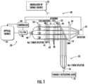
- a sensor receiver is illustrated generally at 20 and includes a Rydberg cell 22 that is configured to be exposed to a radio frequency (RF) signal generated from a modulated RF signal source 24.
- This RF signal source 24 may include a non-modulated RF local oscillator.
- a probe source indicated generally at 28 is configured to generate a plurality of spaced apart pulsed probe beams within the Rydberg cell 22 and generally shown at 30, with the pulsed probe beams being offset in time from one another. It should be understood that one or more Rydberg cells may be used with the probe beams in multiple Rydberg cells.
- a detector 32 is positioned downstream from the Rydberg cell 22. In an example, the detector 32 is formed from a photodetector cell.
- the probe source 28 is configured to generate the plurality of spaced apart pulsed probe beams 30 in an example without scanning and may be formed as an optical source 34 and a pulse shaper 36 that is downstream from the optical source.
- the sensor receiver 20 may work with and without scanning the probe beam.
- the pulse shaper 36 may be an intensity modulator.
- the probe source 28 includes a beam splitter 40, such as a Nx1 fiber splitter, downstream from the pulse shaper 36 and a respective optical delay element 42 in a path of each beam downstream from the beam splitter.
- each optical delay element 42 may be formed as a respective different length of optical fiber shown by the loops indicated as L1, L2, L3 and L4.
- Other delay mechanisms may be used besides fixed pulse delays, such as a changed optical fiber length, such as free space delay elements that may provide more temperature stability and delay tunability.
- a first microlens 44 is positioned adjacent a first side of the Rydberg cell 22 and a second microlens 46 is positioned adjacent a second side of the Rydberg cell as illustrated by the designations ML1 and ML2.
- An excitation source 50 as a coupling laser is coupled to the Rydberg cell 22 and formed, in an example, as a tunable excitation laser 52 and at least one mirror 54, such as a dichroic mirror downstream therefrom to input the output of the excitation laser and excite the rubidium or cesium used within the Rydberg cell 22.
- the Nx1 fiber splitter 56 is a 4x1 splitter and may split the output into four beams from the excitation laser 50 corresponding to the illustrated four probe beams 30.
- a controller 60 is coupled to the Rydberg cell 22, the optical source 34 as the laser probe of the probe source 28 and detector 32.
- a bandpass filter (BPF1) 62 may be included to block the excitation laser 52 and pass the spaced apart probe beams 30.
- a plano convex lens (f1) 64 may focus the probe beams 30 to the detector 32.
- the first microlens 44 and bandpass filter 62 may be formed as a collimator device, e.g., a Thorlabs part no. 50-780, and have a collimator output with about a 0.5 mm spot size beam at 780 nanometers as generated from the optical source 34 as a laser.
- the Rydberg cell 22 is a rubidium Rydberg cell, such as Thorlabs part no. GC19075-RB.
- Other vapors of specific atomic elements may include Cesium (Cs), Potassium (K), Sodium (Na), and possibly Iodine (I).
- the sensor receiver 20 as illustrated will temporally and spectrally shape the signature of the pulsed probe beams 30, and thus, allows an increase in the sampling rate as proportional to the number of beams "N.” Increasing the sampling rate is also dependent on the probe repetition rate.
- the bandwidth of the probe pulses may also help reduce the latency usually incurred by scanning the probe beam across the EIT spectrum. This may reduce the latency from about 1 to 2 orders of magnitude.
- the temporal pulse width of the probe determines its spectral bandwidth through a Fourier transform.
- the incoming RF field may be mapped onto a spectroscopic fingerprint without scanning.
- the graph in FIG. 2 shows a large vertical line 70 at 0 MHz frequency corresponding to the large EIT (Electromagnetically Induced Transparency) profile, which is indicative of how a state-of-the-art Rydberg sensor requires scanning of the narrow band probes.
- the sensor receiver 20 of FIG. 1 shows a large vertical line 70 at 0 MHz frequency corresponding to the large EIT (Electromagnetically Induced Transparency) profile, which is indicative of how a state-of-the-art Rydberg sensor requires scanning of the narrow band probes.
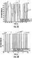
- FIGS. 3A and 3B there are shown graphs where the state-of-the-art Rydberg sensor continuous wave probe signal shows that the atomic system cannot respond to changes in the external RF signal amplitude faster than its characteristic relaxation time. This is evident in waveforms such as that occurring in "on-off key” or OOK for sufficiently high data rates.
- FIG. 3A shows that the sensor receiver 20 of FIG. 1 enables a higher signal-to-noise readout of higher-speed RF data streams.
- an 18 MBaud on off keyed (OOK) RF input was simulated.
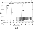
- FIG. 4 there is illustrated a graph that compares the bit error rate (BER) on the vertical axis of an RF OOK data stream with different rates for the state-of-the-art Rydberg atom-based sensor corresponding to the CW probe labeled by line D, and the sensor receiver 20 of FIG. 1 , having different pulsed probes and a repetition rate of 2 MHz, 1 MHz, and 0.5 MHz shown by respective lines labeled A, B and C.
- the sensor receiver 20 of FIG. 1 can measure the RF data rates that are 15 times higher than possible with the state-of-the-art Rydberg sensors, for example, as from 3 MHz to 40+ MHz.
- the CW probe labeled by line D on the graph of FIG. 4 illustrates the state-of-the-art Rydberg sensor, while the pulsed probes labeled A, B and C are examples of the sensor receiver 20 of FIG. 1 .
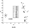
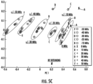
- FIGS. 5A , 5B and 5C there are illustrated graphs of how the sensor receiver 20 of FIG. 1 in the graphs of FIGS. 5B and 5C reduces latency and extracts the RF detuning of an incoming RF data stream without scanning the probe laser in comparison with the performance of a state-of-the-art Rydberg sensor as shown in FIG. 5A .
- FIG. 5B shows a graph of an example of the sensor receiver 20 of FIG. 1 with RF detuning without scanning, and in FIG. 5C with a larger bandwidth of the pulse probes.
- the two clusters of principal component (PC) scores for each RF detuning are illustrated on the left and the right in FIG. 5A .
- the left-hand side for the RF detuning at the different frequencies ranging from 0 MHz to +/-50 MHz is indistinguishable, while the right-hand side is more easily distinguishable.
- FIG. 5B on the other hand, it is evident that with the sensor receiver 20 having the pulsed probe architecture, the RF detuning data can be extracted without scanning the probe laser.
- the PC scores clearly separate the data based on the RF detuning as shown by the separated frequencies and labeled A-F.
- the state-of-the-art Rydberg sensor as shown with its performance in FIG. 5A uses a probe laser as a continuous wave laser that spectrally scans the absorption feature.
- the sensor receiver 20 of FIG. 1 allows spatial-temporal multiplexing where multiple pulsed beams 30 may be in one Rydberg cell 22.
- Pulsing the probe laser also increases the measurement rate of a single beam's absorption feature by replacing the slower spectral scanning techniques of the state-of-the-art Rydberg sensors.
- FIG. 6 there is illustrated generally at 100 a method for receiving an RF signal using the sensor receiver 20 of FIG. 1 .
- the method starts (Block 102) and the Rydberg cell 22 is exposed to the RF signal (Block 104).
- the probe source 28 is operated to generate a plurality of spaced apart pulsed probe beams 30 within the Rydberg cell 22, with the pulsed probe beams being offset in time from each other (Block 106).
- the detector 32 is operated downstream from the Rydberg cell 22 (Block 108) and the process ends (Block 110).
Landscapes
- Physics & Mathematics (AREA)
- General Physics & Mathematics (AREA)
- Electromagnetism (AREA)
- Engineering & Computer Science (AREA)
- Power Engineering (AREA)
- Condensed Matter Physics & Semiconductors (AREA)
- Investigating Or Analysing Materials By Optical Means (AREA)
- Radar Systems Or Details Thereof (AREA)
- Optical Radar Systems And Details Thereof (AREA)
Claims (10)
- Récepteur de capteur (20) comprenant:une cellule de Rydberg (22) configurée pour être exposée à un signal de radiofréquence (RF); caractérisée parune source de sonde (28) configurée pour générer plusieurs faisceaux de sonde pulsés espacés (30) à l'intérieur de la cellule de Rydberg, les faisceaux de sonde pulsés étant décalés dans le temps les uns par rapport aux autres; etun détecteur (32) en aval de la cellule de Rydberg.
- Le récepteur de capteur de la revendication 1, dans lequel la source de sonde est configurée pour générer la pluralité de faisceaux de sonde pulsés espacés sans balayage.
- Le récepteur de capteur de la revendication 1, dans lequel la source de la sonde comprend une source optique (34), et une mise en forme d'impulsion (36) en aval de la source optique.
- Le récepteur de capteur de la revendication 3, dans lequel la source de sonde comprend un séparateur de faisceau (40) en aval de la mise en forme d'impulsion, et un élément de retard optique respectif (42) dans un chemin de chaque faisceau en aval du séparateur de faisceau.
- Le récepteur de capteur de la revendication 4, dans lequel chaque élément de retard optique comprend une longueur différente de fibre optique.
- Le récepteur capteur de la revendication 1, comprenant un contrôleur (60) couplé à la cellule de Rydberg, à la source de la sonde et au détecteur.
- Une méthode de réception d'un signal de radiofréquence (RF) comprenant:exposer une cellule de Rydberg (22) au signal RF; caractérisé parfaire fonctionner une source de sonde (28) pour générer une pluralité de faisceaux de sonde pulsés espacés (30) dans la cellule de Rydberg, les faisceaux de sonde pulsés étant décalés dans le temps les uns par rapport aux autres; etfaire fonctionner un détecteur (32) en aval de la cellule de Rydberg.
- La méthode de la revendication 7, comprenant générer la pluralité de faisceaux de sonde pulsés espacés sans balayage.
- La méthode de la revendication 7, dans laquelle la source de la sonde comprend une source optique (34), une mise en forme d'impulsion (36) en aval de la source optique, un séparateur de faisceau (40) en aval de la mise en forme d'impulsion, et un élément de retard optique respectif (42) dans un chemin de chaque faisceau en aval du séparateur de faisceau.
- La méthode de la revendication 7 comprenant faire fonctionner une source d'excitation (50) couplée à la cellule de Rydberg.
Applications Claiming Priority (1)
| Application Number | Priority Date | Filing Date | Title |
|---|---|---|---|
| US17/445,316 US11598798B1 (en) | 2021-08-18 | 2021-08-18 | Sensor receiver having Rydberg cell and spaced apart pulsed probe beams and associated methods |
Publications (2)
| Publication Number | Publication Date |
|---|---|
| EP4137825A1 EP4137825A1 (fr) | 2023-02-22 |
| EP4137825B1 true EP4137825B1 (fr) | 2024-01-31 |
Family
ID=81326986
Family Applications (1)
| Application Number | Title | Priority Date | Filing Date |
|---|---|---|---|
| EP22166078.0A Active EP4137825B1 (fr) | 2021-08-18 | 2022-03-31 | Récepteur de capteur comportant une cellule de rydberg et des faisceaux de sonde pulsés espacés les uns des autres et procédés associés |
Country Status (2)
| Country | Link |
|---|---|
| US (1) | US11598798B1 (fr) |
| EP (1) | EP4137825B1 (fr) |
Families Citing this family (10)
| Publication number | Priority date | Publication date | Assignee | Title |
|---|---|---|---|---|
| GB2605123B (en) * | 2021-03-01 | 2023-04-26 | British Telecomm | Electromagnetic field detector |
| US12332372B2 (en) | 2021-08-18 | 2025-06-17 | Eagle Technology, Llc | Sensor receiver having Rydberg cell and RF data rate greater than reciprocal of temporal pulse width and associated methods |
| CN121890014A (zh) * | 2023-09-22 | 2026-04-17 | 英国电讯有限公司 | 用于无线电信网络的装置、包括该装置的系统和操作该装置的方法 |
| US12613264B2 (en) | 2024-01-18 | 2026-04-28 | Eagle Technology, Llc | Rydberg sensor having an optical fiber path feeding Rydberg sensing regions and associated methods |
| EP4607821A1 (fr) | 2024-02-13 | 2025-08-27 | Eagle Technology, LLC | Système ayant un noeud récepteur et un noeud capteur de rydberg espacé et procédés associés |
| US12416716B1 (en) * | 2024-03-11 | 2025-09-16 | Quantum Valley Ideas Laboratories | Methods for sensing doppler shifts |
| US20260009834A1 (en) | 2024-07-03 | 2026-01-08 | Eagle Technology, Llc | Rydberg sensor having quantum radio frequency (qrf) cavity with optical amplifier and associated methods |
| US20260009833A1 (en) | 2024-07-03 | 2026-01-08 | Eagle Technology, Llc | Rydberg sensor having rydberg sensing regions with at least one optical amplifier and associated methods |
| US20260050022A1 (en) | 2024-08-13 | 2026-02-19 | Eagle Technology, Llc | Sensor receiver having a sweeping probe laser beam generated within a rydberg cell and associated methods |
| US20260072066A1 (en) | 2024-09-12 | 2026-03-12 | Eagle Technology, Llc | Rydberg sensor having an array of quantum radio frequency (qrf) cavities and associated methods |
Family Cites Families (9)
| Publication number | Priority date | Publication date | Assignee | Title |
|---|---|---|---|---|
| JP5764566B2 (ja) * | 2009-10-02 | 2015-08-19 | イムラ アメリカ インコーポレイテッド | モード同期レーザによる光信号処理 |
| EP3308146B1 (fr) | 2015-06-15 | 2020-02-26 | The Regents of The University of Michigan | Capteur de champ électrique d'un rayonnement électromagnétique basé sur les atomes |
| KR20260022466A (ko) * | 2017-12-18 | 2026-02-19 | 리드베르크 테크놀로지스 인코퍼레이티드 | 원자 기반 전자기장 감지 요소 및 측정 시스템 |
| US11349569B2 (en) | 2018-10-26 | 2022-05-31 | Raytheon Company | Methods and apparatus for implementing an optical transceiver using a vapor cell |
| EP3906418B1 (fr) * | 2018-12-31 | 2023-03-01 | Quantum Valley Ideas Laboratories | Imagerie de champs électromagnétiques |
| US11002777B2 (en) * | 2019-01-23 | 2021-05-11 | ColdQuanta, Inc. | Microwave sensor using rydberg particles |
| US10979147B2 (en) | 2019-03-11 | 2021-04-13 | Government Of The United States Of America, As Represented By The Secretary Of Commerce | Rydberg atom mixer and determining phase of modulated carrier radiation |
| US11435386B2 (en) * | 2019-03-15 | 2022-09-06 | Government Of The United States Of America, As Represented By The Secretary Of Commerce | Si-traceable Rydberg atom radiofrequency power meter and determining power of radio frequency radiation |
| US10605840B1 (en) * | 2019-10-21 | 2020-03-31 | Quantum Valley Ideas Laboratories | Vapor cells having reduced scattering cross-sections and their methods of manufacture |
-
2021
- 2021-08-18 US US17/445,316 patent/US11598798B1/en active Active
-
2022
- 2022-03-31 EP EP22166078.0A patent/EP4137825B1/fr active Active
Also Published As
| Publication number | Publication date |
|---|---|
| US11598798B1 (en) | 2023-03-07 |
| EP4137825A1 (fr) | 2023-02-22 |
| US20230058843A1 (en) | 2023-02-23 |
Similar Documents
| Publication | Publication Date | Title |
|---|---|---|
| EP4137825B1 (fr) | Récepteur de capteur comportant une cellule de rydberg et des faisceaux de sonde pulsés espacés les uns des autres et procédés associés | |
| US11815538B2 (en) | Sensor receiver having a Rydberg cell with a plurality of excitation sources and associated methods | |
| US11112310B2 (en) | Dual-comb spectroscopy | |
| US12332372B2 (en) | Sensor receiver having Rydberg cell and RF data rate greater than reciprocal of temporal pulse width and associated methods | |
| US5847817A (en) | Method for extending range and sensitivity of a fiber optic micro-doppler ladar system and apparatus therefor | |
| US6078394A (en) | Wavelength manager | |
| EP4302104B1 (fr) | Détecteur de champ électromagnétique | |
| EP4176273B1 (fr) | Recherche de direction d'hyperfréquences sur la base d'une molécule de rydberg | |
| US10215845B2 (en) | Simultaneous ranging and remote chemical sensing utilizing optical dispersion or absorption spectroscopy | |
| US20170067822A1 (en) | Cavity enhanced spectroscopy using off-axis paths | |
| EP4679108A1 (fr) | Capteur de rydberg ayant des régions de détection de rydberg comportant au moins un amplificateur optique et procédés associés | |
| US12253465B2 (en) | Methods and systems for open path gas detection | |
| CA2732685A1 (fr) | Systeme et procede d'extraction de la magnitude et de la phase par modulation du trajet | |
| US12613264B2 (en) | Rydberg sensor having an optical fiber path feeding Rydberg sensing regions and associated methods | |
| EP4675287A1 (fr) | Capteur rydberg ayant une cavité de radiofréquence quantique (qrf) avec amplificateur optique et procédés associés | |
| US20110110674A1 (en) | Method and device for processing terahertz waves | |
| EP2290401B1 (fr) | Capteur à distance d'impulsion courte ultra-stable | |
| USH1059H (en) | Fiber optic RF signal channelizer | |
| US20200386859A1 (en) | Method for providing a detection signal for objects to be detected | |
| KR101515980B1 (ko) | 바람장 측정과 방사성물질 동시측정 라이다 장치 | |
| US20260072066A1 (en) | Rydberg sensor having an array of quantum radio frequency (qrf) cavities and associated methods | |
| US20260050022A1 (en) | Sensor receiver having a sweeping probe laser beam generated within a rydberg cell and associated methods | |
| US20260050023A1 (en) | Sensor receiver having rydberg cell sensing atoms that move with respect to probe laser beam and associated methods | |
| US20250155559A1 (en) | Frequency-Modulated Continuous Wave LiDAR Device | |
| US11150137B2 (en) | Thermal imaging with an integrated photonics chip |
Legal Events
| Date | Code | Title | Description |
|---|---|---|---|
| PUAI | Public reference made under article 153(3) epc to a published international application that has entered the european phase |
Free format text: ORIGINAL CODE: 0009012 |
|
| STAA | Information on the status of an ep patent application or granted ep patent |
Free format text: STATUS: REQUEST FOR EXAMINATION WAS MADE |
|
| 17P | Request for examination filed |
Effective date: 20220331 |
|
| AK | Designated contracting states |
Kind code of ref document: A1 Designated state(s): AL AT BE BG CH CY CZ DE DK EE ES FI FR GB GR HR HU IE IS IT LI LT LU LV MC MK MT NL NO PL PT RO RS SE SI SK SM TR |
|
| RIC1 | Information provided on ipc code assigned before grant |
Ipc: G01R 33/032 20060101ALI20230707BHEP Ipc: G01R 29/08 20060101AFI20230707BHEP |
|
| GRAP | Despatch of communication of intention to grant a patent |
Free format text: ORIGINAL CODE: EPIDOSNIGR1 |
|
| STAA | Information on the status of an ep patent application or granted ep patent |
Free format text: STATUS: GRANT OF PATENT IS INTENDED |
|
| INTG | Intention to grant announced |
Effective date: 20230921 |
|
| GRAS | Grant fee paid |
Free format text: ORIGINAL CODE: EPIDOSNIGR3 |
|
| GRAA | (expected) grant |
Free format text: ORIGINAL CODE: 0009210 |
|
| STAA | Information on the status of an ep patent application or granted ep patent |
Free format text: STATUS: THE PATENT HAS BEEN GRANTED |
|
| P01 | Opt-out of the competence of the unified patent court (upc) registered |
Effective date: 20231218 |
|
| AK | Designated contracting states |
Kind code of ref document: B1 Designated state(s): AL AT BE BG CH CY CZ DE DK EE ES FI FR GB GR HR HU IE IS IT LI LT LU LV MC MK MT NL NO PL PT RO RS SE SI SK SM TR |
|
| REG | Reference to a national code |
Ref country code: GB Ref legal event code: FG4D Ref country code: CH Ref legal event code: EP |
|
| REG | Reference to a national code |
Ref country code: DE Ref legal event code: R096 Ref document number: 602022001734 Country of ref document: DE |
|
| REG | Reference to a national code |
Ref country code: IE Ref legal event code: FG4D |
|
| REG | Reference to a national code |
Ref country code: LT Ref legal event code: MG9D |
|
| REG | Reference to a national code |
Ref country code: NL Ref legal event code: MP Effective date: 20240131 |
|
| PG25 | Lapsed in a contracting state [announced via postgrant information from national office to epo] |
Ref country code: IS Free format text: LAPSE BECAUSE OF FAILURE TO SUBMIT A TRANSLATION OF THE DESCRIPTION OR TO PAY THE FEE WITHIN THE PRESCRIBED TIME-LIMIT Effective date: 20240531 |
|
| PG25 | Lapsed in a contracting state [announced via postgrant information from national office to epo] |
Ref country code: LT Free format text: LAPSE BECAUSE OF FAILURE TO SUBMIT A TRANSLATION OF THE DESCRIPTION OR TO PAY THE FEE WITHIN THE PRESCRIBED TIME-LIMIT Effective date: 20240131 |
|
| PG25 | Lapsed in a contracting state [announced via postgrant information from national office to epo] |
Ref country code: GR Free format text: LAPSE BECAUSE OF FAILURE TO SUBMIT A TRANSLATION OF THE DESCRIPTION OR TO PAY THE FEE WITHIN THE PRESCRIBED TIME-LIMIT Effective date: 20240501 |
|
| REG | Reference to a national code |
Ref country code: AT Ref legal event code: MK05 Ref document number: 1654223 Country of ref document: AT Kind code of ref document: T Effective date: 20240131 |
|
| PG25 | Lapsed in a contracting state [announced via postgrant information from national office to epo] |
Ref country code: RS Free format text: LAPSE BECAUSE OF FAILURE TO SUBMIT A TRANSLATION OF THE DESCRIPTION OR TO PAY THE FEE WITHIN THE PRESCRIBED TIME-LIMIT Effective date: 20240430 Ref country code: HR Free format text: LAPSE BECAUSE OF FAILURE TO SUBMIT A TRANSLATION OF THE DESCRIPTION OR TO PAY THE FEE WITHIN THE PRESCRIBED TIME-LIMIT Effective date: 20240131 Ref country code: NL Free format text: LAPSE BECAUSE OF FAILURE TO SUBMIT A TRANSLATION OF THE DESCRIPTION OR TO PAY THE FEE WITHIN THE PRESCRIBED TIME-LIMIT Effective date: 20240131 |
|
| PG25 | Lapsed in a contracting state [announced via postgrant information from national office to epo] |
Ref country code: ES Free format text: LAPSE BECAUSE OF FAILURE TO SUBMIT A TRANSLATION OF THE DESCRIPTION OR TO PAY THE FEE WITHIN THE PRESCRIBED TIME-LIMIT Effective date: 20240131 |
|
| PG25 | Lapsed in a contracting state [announced via postgrant information from national office to epo] |
Ref country code: AT Free format text: LAPSE BECAUSE OF FAILURE TO SUBMIT A TRANSLATION OF THE DESCRIPTION OR TO PAY THE FEE WITHIN THE PRESCRIBED TIME-LIMIT Effective date: 20240131 |
|
| PG25 | Lapsed in a contracting state [announced via postgrant information from national office to epo] |
Ref country code: RS Free format text: LAPSE BECAUSE OF FAILURE TO SUBMIT A TRANSLATION OF THE DESCRIPTION OR TO PAY THE FEE WITHIN THE PRESCRIBED TIME-LIMIT Effective date: 20240430 Ref country code: NO Free format text: LAPSE BECAUSE OF FAILURE TO SUBMIT A TRANSLATION OF THE DESCRIPTION OR TO PAY THE FEE WITHIN THE PRESCRIBED TIME-LIMIT Effective date: 20240430 Ref country code: NL Free format text: LAPSE BECAUSE OF FAILURE TO SUBMIT A TRANSLATION OF THE DESCRIPTION OR TO PAY THE FEE WITHIN THE PRESCRIBED TIME-LIMIT Effective date: 20240131 Ref country code: LT Free format text: LAPSE BECAUSE OF FAILURE TO SUBMIT A TRANSLATION OF THE DESCRIPTION OR TO PAY THE FEE WITHIN THE PRESCRIBED TIME-LIMIT Effective date: 20240131 Ref country code: IS Free format text: LAPSE BECAUSE OF FAILURE TO SUBMIT A TRANSLATION OF THE DESCRIPTION OR TO PAY THE FEE WITHIN THE PRESCRIBED TIME-LIMIT Effective date: 20240531 Ref country code: HR Free format text: LAPSE BECAUSE OF FAILURE TO SUBMIT A TRANSLATION OF THE DESCRIPTION OR TO PAY THE FEE WITHIN THE PRESCRIBED TIME-LIMIT Effective date: 20240131 Ref country code: GR Free format text: LAPSE BECAUSE OF FAILURE TO SUBMIT A TRANSLATION OF THE DESCRIPTION OR TO PAY THE FEE WITHIN THE PRESCRIBED TIME-LIMIT Effective date: 20240501 Ref country code: FI Free format text: LAPSE BECAUSE OF FAILURE TO SUBMIT A TRANSLATION OF THE DESCRIPTION OR TO PAY THE FEE WITHIN THE PRESCRIBED TIME-LIMIT Effective date: 20240131 Ref country code: ES Free format text: LAPSE BECAUSE OF FAILURE TO SUBMIT A TRANSLATION OF THE DESCRIPTION OR TO PAY THE FEE WITHIN THE PRESCRIBED TIME-LIMIT Effective date: 20240131 Ref country code: BG Free format text: LAPSE BECAUSE OF FAILURE TO SUBMIT A TRANSLATION OF THE DESCRIPTION OR TO PAY THE FEE WITHIN THE PRESCRIBED TIME-LIMIT Effective date: 20240131 Ref country code: AT Free format text: LAPSE BECAUSE OF FAILURE TO SUBMIT A TRANSLATION OF THE DESCRIPTION OR TO PAY THE FEE WITHIN THE PRESCRIBED TIME-LIMIT Effective date: 20240131 |
|
| PG25 | Lapsed in a contracting state [announced via postgrant information from national office to epo] |
Ref country code: PT Free format text: LAPSE BECAUSE OF FAILURE TO SUBMIT A TRANSLATION OF THE DESCRIPTION OR TO PAY THE FEE WITHIN THE PRESCRIBED TIME-LIMIT Effective date: 20240531 Ref country code: PL Free format text: LAPSE BECAUSE OF FAILURE TO SUBMIT A TRANSLATION OF THE DESCRIPTION OR TO PAY THE FEE WITHIN THE PRESCRIBED TIME-LIMIT Effective date: 20240131 |
|
| PG25 | Lapsed in a contracting state [announced via postgrant information from national office to epo] |
Ref country code: SE Free format text: LAPSE BECAUSE OF FAILURE TO SUBMIT A TRANSLATION OF THE DESCRIPTION OR TO PAY THE FEE WITHIN THE PRESCRIBED TIME-LIMIT Effective date: 20240131 Ref country code: PT Free format text: LAPSE BECAUSE OF FAILURE TO SUBMIT A TRANSLATION OF THE DESCRIPTION OR TO PAY THE FEE WITHIN THE PRESCRIBED TIME-LIMIT Effective date: 20240531 Ref country code: PL Free format text: LAPSE BECAUSE OF FAILURE TO SUBMIT A TRANSLATION OF THE DESCRIPTION OR TO PAY THE FEE WITHIN THE PRESCRIBED TIME-LIMIT Effective date: 20240131 Ref country code: LV Free format text: LAPSE BECAUSE OF FAILURE TO SUBMIT A TRANSLATION OF THE DESCRIPTION OR TO PAY THE FEE WITHIN THE PRESCRIBED TIME-LIMIT Effective date: 20240131 |
|
| PG25 | Lapsed in a contracting state [announced via postgrant information from national office to epo] |
Ref country code: DK Free format text: LAPSE BECAUSE OF FAILURE TO SUBMIT A TRANSLATION OF THE DESCRIPTION OR TO PAY THE FEE WITHIN THE PRESCRIBED TIME-LIMIT Effective date: 20240131 |
|
| PG25 | Lapsed in a contracting state [announced via postgrant information from national office to epo] |
Ref country code: SM Free format text: LAPSE BECAUSE OF FAILURE TO SUBMIT A TRANSLATION OF THE DESCRIPTION OR TO PAY THE FEE WITHIN THE PRESCRIBED TIME-LIMIT Effective date: 20240131 |
|
| PG25 | Lapsed in a contracting state [announced via postgrant information from national office to epo] |
Ref country code: CZ Free format text: LAPSE BECAUSE OF FAILURE TO SUBMIT A TRANSLATION OF THE DESCRIPTION OR TO PAY THE FEE WITHIN THE PRESCRIBED TIME-LIMIT Effective date: 20240131 Ref country code: EE Free format text: LAPSE BECAUSE OF FAILURE TO SUBMIT A TRANSLATION OF THE DESCRIPTION OR TO PAY THE FEE WITHIN THE PRESCRIBED TIME-LIMIT Effective date: 20240131 |
|
| PG25 | Lapsed in a contracting state [announced via postgrant information from national office to epo] |
Ref country code: SK Free format text: LAPSE BECAUSE OF FAILURE TO SUBMIT A TRANSLATION OF THE DESCRIPTION OR TO PAY THE FEE WITHIN THE PRESCRIBED TIME-LIMIT Effective date: 20240131 |
|
| PG25 | Lapsed in a contracting state [announced via postgrant information from national office to epo] |
Ref country code: SM Free format text: LAPSE BECAUSE OF FAILURE TO SUBMIT A TRANSLATION OF THE DESCRIPTION OR TO PAY THE FEE WITHIN THE PRESCRIBED TIME-LIMIT Effective date: 20240131 Ref country code: SK Free format text: LAPSE BECAUSE OF FAILURE TO SUBMIT A TRANSLATION OF THE DESCRIPTION OR TO PAY THE FEE WITHIN THE PRESCRIBED TIME-LIMIT Effective date: 20240131 Ref country code: RO Free format text: LAPSE BECAUSE OF FAILURE TO SUBMIT A TRANSLATION OF THE DESCRIPTION OR TO PAY THE FEE WITHIN THE PRESCRIBED TIME-LIMIT Effective date: 20240131 Ref country code: EE Free format text: LAPSE BECAUSE OF FAILURE TO SUBMIT A TRANSLATION OF THE DESCRIPTION OR TO PAY THE FEE WITHIN THE PRESCRIBED TIME-LIMIT Effective date: 20240131 Ref country code: DK Free format text: LAPSE BECAUSE OF FAILURE TO SUBMIT A TRANSLATION OF THE DESCRIPTION OR TO PAY THE FEE WITHIN THE PRESCRIBED TIME-LIMIT Effective date: 20240131 Ref country code: CZ Free format text: LAPSE BECAUSE OF FAILURE TO SUBMIT A TRANSLATION OF THE DESCRIPTION OR TO PAY THE FEE WITHIN THE PRESCRIBED TIME-LIMIT Effective date: 20240131 |
|
| REG | Reference to a national code |
Ref country code: DE Ref legal event code: R097 Ref document number: 602022001734 Country of ref document: DE |
|
| PG25 | Lapsed in a contracting state [announced via postgrant information from national office to epo] |
Ref country code: LU Free format text: LAPSE BECAUSE OF NON-PAYMENT OF DUE FEES Effective date: 20240331 |
|
| PG25 | Lapsed in a contracting state [announced via postgrant information from national office to epo] |
Ref country code: MC Free format text: LAPSE BECAUSE OF FAILURE TO SUBMIT A TRANSLATION OF THE DESCRIPTION OR TO PAY THE FEE WITHIN THE PRESCRIBED TIME-LIMIT Effective date: 20240131 |
|
| PG25 | Lapsed in a contracting state [announced via postgrant information from national office to epo] |
Ref country code: MC Free format text: LAPSE BECAUSE OF FAILURE TO SUBMIT A TRANSLATION OF THE DESCRIPTION OR TO PAY THE FEE WITHIN THE PRESCRIBED TIME-LIMIT Effective date: 20240131 Ref country code: LU Free format text: LAPSE BECAUSE OF NON-PAYMENT OF DUE FEES Effective date: 20240331 |
|
| PG25 | Lapsed in a contracting state [announced via postgrant information from national office to epo] |
Ref country code: IT Free format text: LAPSE BECAUSE OF FAILURE TO SUBMIT A TRANSLATION OF THE DESCRIPTION OR TO PAY THE FEE WITHIN THE PRESCRIBED TIME-LIMIT Effective date: 20240131 |
|
| PLBE | No opposition filed within time limit |
Free format text: ORIGINAL CODE: 0009261 |
|
| STAA | Information on the status of an ep patent application or granted ep patent |
Free format text: STATUS: NO OPPOSITION FILED WITHIN TIME LIMIT |
|
| REG | Reference to a national code |
Ref country code: BE Ref legal event code: MM Effective date: 20240331 |
|
| PG25 | Lapsed in a contracting state [announced via postgrant information from national office to epo] |
Ref country code: IT Free format text: LAPSE BECAUSE OF FAILURE TO SUBMIT A TRANSLATION OF THE DESCRIPTION OR TO PAY THE FEE WITHIN THE PRESCRIBED TIME-LIMIT Effective date: 20240131 |
|
| 26N | No opposition filed |
Effective date: 20241101 |
|
| PG25 | Lapsed in a contracting state [announced via postgrant information from national office to epo] |
Ref country code: BE Free format text: LAPSE BECAUSE OF NON-PAYMENT OF DUE FEES Effective date: 20240331 |
|
| PG25 | Lapsed in a contracting state [announced via postgrant information from national office to epo] |
Ref country code: FR Free format text: LAPSE BECAUSE OF NON-PAYMENT OF DUE FEES Effective date: 20240331 |
|
| PG25 | Lapsed in a contracting state [announced via postgrant information from national office to epo] |
Ref country code: IE Free format text: LAPSE BECAUSE OF NON-PAYMENT OF DUE FEES Effective date: 20240331 |
|
| PG25 | Lapsed in a contracting state [announced via postgrant information from national office to epo] |
Ref country code: IE Free format text: LAPSE BECAUSE OF NON-PAYMENT OF DUE FEES Effective date: 20240331 Ref country code: FR Free format text: LAPSE BECAUSE OF NON-PAYMENT OF DUE FEES Effective date: 20240331 Ref country code: BE Free format text: LAPSE BECAUSE OF NON-PAYMENT OF DUE FEES Effective date: 20240331 |
|
| PG25 | Lapsed in a contracting state [announced via postgrant information from national office to epo] |
Ref country code: SI Free format text: LAPSE BECAUSE OF FAILURE TO SUBMIT A TRANSLATION OF THE DESCRIPTION OR TO PAY THE FEE WITHIN THE PRESCRIBED TIME-LIMIT Effective date: 20240131 |
|
| PG25 | Lapsed in a contracting state [announced via postgrant information from national office to epo] |
Ref country code: CY Free format text: LAPSE BECAUSE OF FAILURE TO SUBMIT A TRANSLATION OF THE DESCRIPTION OR TO PAY THE FEE WITHIN THE PRESCRIBED TIME-LIMIT; INVALID AB INITIO Effective date: 20220331 |
|
| REG | Reference to a national code |
Ref country code: CH Ref legal event code: H13 Free format text: ST27 STATUS EVENT CODE: U-0-0-H10-H13 (AS PROVIDED BY THE NATIONAL OFFICE) Effective date: 20251023 |
|
| PG25 | Lapsed in a contracting state [announced via postgrant information from national office to epo] |
Ref country code: TR Free format text: LAPSE BECAUSE OF FAILURE TO SUBMIT A TRANSLATION OF THE DESCRIPTION OR TO PAY THE FEE WITHIN THE PRESCRIBED TIME-LIMIT Effective date: 20240131 |
|
| PG25 | Lapsed in a contracting state [announced via postgrant information from national office to epo] |
Ref country code: CH Free format text: LAPSE BECAUSE OF NON-PAYMENT OF DUE FEES Effective date: 20250331 |
|
| PGFP | Annual fee paid to national office [announced via postgrant information from national office to epo] |
Ref country code: GB Payment date: 20260327 Year of fee payment: 5 |
|
| PGFP | Annual fee paid to national office [announced via postgrant information from national office to epo] |
Ref country code: DE Payment date: 20260327 Year of fee payment: 5 |