EP4137847A1 - Détecteur de position de neutrons - Google Patents
Détecteur de position de neutrons Download PDFInfo
- Publication number
- EP4137847A1 EP4137847A1 EP20931456.6A EP20931456A EP4137847A1 EP 4137847 A1 EP4137847 A1 EP 4137847A1 EP 20931456 A EP20931456 A EP 20931456A EP 4137847 A1 EP4137847 A1 EP 4137847A1
- Authority
- EP
- European Patent Office
- Prior art keywords
- gas
- neutron
- position detector
- enclosure
- nitrogen
- Prior art date
- Legal status (The legal status is an assumption and is not a legal conclusion. Google has not performed a legal analysis and makes no representation as to the accuracy of the status listed.)
- Granted
Links
Images

Classifications
-
- G—PHYSICS
- G01—MEASURING; TESTING
- G01T—MEASUREMENT OF NUCLEAR OR X-RADIATION
- G01T3/00—Measuring neutron radiation
- G01T3/006—Measuring neutron radiation using self-powered detectors (for neutrons as well as for Y- or X-rays), e.g. using Compton-effect (Compton diodes) or photo-emission or a (n,B) nuclear reaction
-
- G—PHYSICS
- G01—MEASURING; TESTING
- G01T—MEASUREMENT OF NUCLEAR OR X-RADIATION
- G01T3/00—Measuring neutron radiation
- G01T3/008—Measuring neutron radiation using an ionisation chamber filled with a gas, liquid or solid, e.g. frozen liquid, dielectric
-
- H—ELECTRICITY
- H01—ELECTRIC ELEMENTS
- H01J—ELECTRIC DISCHARGE TUBES OR DISCHARGE LAMPS
- H01J47/00—Tubes for determining the presence, intensity, density or energy of radiation or particles
- H01J47/12—Neutron detector tubes, e.g. BF3 tubes
-
- H—ELECTRICITY
- H01—ELECTRIC ELEMENTS
- H01J—ELECTRIC DISCHARGE TUBES OR DISCHARGE LAMPS
- H01J47/00—Tubes for determining the presence, intensity, density or energy of radiation or particles
- H01J47/12—Neutron detector tubes, e.g. BF3 tubes
- H01J47/125—Helium ionisation detectors
-
- Y—GENERAL TAGGING OF NEW TECHNOLOGICAL DEVELOPMENTS; GENERAL TAGGING OF CROSS-SECTIONAL TECHNOLOGIES SPANNING OVER SEVERAL SECTIONS OF THE IPC; TECHNICAL SUBJECTS COVERED BY FORMER USPC CROSS-REFERENCE ART COLLECTIONS [XRACs] AND DIGESTS
- Y02—TECHNOLOGIES OR APPLICATIONS FOR MITIGATION OR ADAPTATION AGAINST CLIMATE CHANGE
- Y02E—REDUCTION OF GREENHOUSE GAS [GHG] EMISSIONS, RELATED TO ENERGY GENERATION, TRANSMISSION OR DISTRIBUTION
- Y02E30/00—Energy generation of nuclear origin
- Y02E30/30—Nuclear fission reactors
Definitions
- Embodiments of the invention relate to a neutron position detector used in the position distribution measurement of neutrons.
- neutron position detectors are used in applications in an accelerator facility in which neutrons are irradiated on a sample to be examined and the characteristics of the sample are examined by detecting the scattering of the neutrons, etc.
- a neutron position detector includes a position-sensitive neutron detection proportional counter (PSD) as a neutron position detector, a processing circuit that calculates the neutron incident position by processing a charge output from the neutron position detector, etc.
- PSD position-sensitive neutron detection proportional counter
- a neutron position detector includes a tubular enclosure used as a cathode; an anode is located at the axial center inside the enclosure; and a gas that includes a 3 He gas and an additive gas are sealed inside the enclosure. Then, when a neutron enters the enclosure, the 3 He inside the gas has a nuclear reaction with the neutron that produces a proton and tritium; the proton and the tritium travel through the gas and ionize the surrounding gas; and the ionized charge is collected by the anode. Then, the incident position of the neutron is detected in a processing circuit based on the output charge from the two ends of the anode.
- a neutron position detector it is therefore desirable for a neutron position detector to have a longer life while ensuring the position resolution, i.e., the detection accuracy of the incident position of the neutron.
- Patent Document 1 JP 6228340
- the invention is directed to provide a neutron position detector that can have a longer life while ensuring the position resolution, i.e., the detection accuracy of the incident position of the neutron.
- a neutron position detector of the embodiment includes a tubular enclosure used as a cathode, an anode located at an axial center inside the enclosure, and a gas that includes a 3 He gas and an additive gas and is sealed inside the enclosure.
- the additive gas includes nitrogen as a quenching gas, and argon as a gas that reduces the ranges of reaction products of a neutron and the 3 He gas.
- a neutron position detection device 10 includes a neutron position detector 11, a high-voltage power supply 12, and a processing circuit 13.
- the processing circuit 13 includes preamplifiers 14a and 14b, an AD converter 15, an arithmetic unit 16, etc.
- the neutron position detector 11 is a one-dimensional position-sensitive neutron detection proportional counter (PSD).
- PSD position-sensitive neutron detection proportional counter
- the neutron position detector 11 includes a tubular enclosure 20 that is a cathode, an anode 21 located at the axial center of the enclosure 20, terminal parts 22a and 22b located at the two ends of the enclosure 20, and a gas 23 sealed inside the enclosure 20.
- the enclosure 20 has a circular tubular shape that is long in the axial direction and sealed at two ends.
- a sealed space 24 is provided inside the enclosure 20.
- the anode 21 is a resistive core wire (a resistive metal wire) having a constant resistance value per unit length.
- the anode 21 is located along the axial center inside the enclosure 20; and the two ends of the anode 21 are linked to and electrically connected to the terminal parts 22a and 22b.
- the terminal parts 22a and 22b are located at the two ends of the enclosure 20 in an insulated state with respect to the enclosure 20.
- the two ends of the anode 21 are linked to and electrically connected to the terminal parts 22a and 22b.
- the gas 23 is sealed in the sealed space 24 of the enclosure 20.
- the gas 23 includes a 3 He gas that is ionized by absorbing the neutrons, and an additive gas that is added to the 3 He gas.
- the partial pressure of the 3 He gas is arbitrarily set according to the specification of the neutron detection efficiency and is, for example, in the range of 10 to 20 atm.
- the additive gas includes nitrogen as a quenching gas that is a molecular gas, and an argon for reducing the ranges of protons and tritium that are reaction products of the neutrons and the 3 He gas.
- nitrogen as a quenching gas that is a molecular gas
- argon for reducing the ranges of protons and tritium that are reaction products of the neutrons and the 3 He gas.
- the relationship of d ⁇ pN2 > 0.03 is favorable, where d (cm) is the inner diameter of the enclosure 20, and pN2 (atm) is the partial pressure of nitrogen.
- the relationship is favorable when the partial pressure of the argon added to the 3 He is greater than the partial pressure of nitrogen. It is favorable for the partial pressure of the argon added to the 3 He to be in the range of 1 to 3 atm.
- composition of the gas 23 is such that the partial pressure of the 3 He gas and the partial pressure of the additive gas are set so that the total of the ranges of the proton and tritium inside the gas 23 is, for example, in the range of 2.0 to 2.7 mm.
- the high-voltage power supply 12 applies an operating voltage between the anode 21 and the enclosure 20 that is the cathode.
- the operating voltage is set to the range of 2.0 to 2.5 kV so that the output charge from the anode 21 is, for example, 2 to 5 pC.
- the preamplifiers 14a and 14b of the processing circuit 13 respectively convert the output charges from the two ends of the neutron position detector 11 (hereinbelow, called the two detector ends) into electrical signals and output the electrical signals.
- the preamplifiers 14a and 14b include coupling capacitors 30a and 30b that cut high-voltage components applied to the neutron position detector 11, op-amps 31a and 31b that convert the output charges after cutting high-voltage components into prescribed electrical signals, etc.
- a higher capacitance and lower distortion due to lower impedance may be realized by connecting two of each of the coupling capacitors 30a and 30b in parallel.
- JFET input operational amplifiers as the op-amps 31a and 31b to suppress the operation delay distortion to a minimum.
- the AD converter 15 converts the electrical signals (the analog signals) of the two detector ends output from the preamplifiers 14a and 14b into digital signals (waveform signals).
- the AD converter 15 includes an element having a resolution of not less than 14 bits.
- the AD converter 15 may include an element having a resolution of 16 bits.
- the arithmetic unit 16 determines the wave heights from the waveform data of the electrical signals of the two detector ends digitized by the AD converter 15 and calculates the incident position of the neutron in the axial direction of the neutron position detector 11 based on the ratio of the wave heights.
- the operating voltage is applied between the anode 21 and the enclosure 20 that is the cathode by the high-voltage power supply 12.
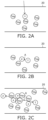
- FIGS. 2A and B when a neutron n enters the enclosure 20, a nuclear reaction occurs between the neutron n and the 3 He gas (n + 3 He -> p + T + 765 keV), and a proton p and tritium T that are reaction products are produced.
- "A” shown in FIG. 2B is the position at which the nuclear reaction occurred and is the position at which the proton p and the tritium T were produced.
- the proton p has about 574 keV of energy
- the tritium T has 191 keV of energy
- the proton p and the tritium T travel through the gas 23 in mutually-opposite directions to gradually stop due to the loss of energy due to colliding with the atoms and molecules of the surrounding gas 23.
- the proton p and the tritium T collide with the gas 23
- a portion of the energy of the proton p and the tritium T is transferred to the gas 23 to ionize the gas 23 and generate a charge e.
- the generated charge e is collected by the anode 21 due to the electric field formed between the anode 21 and the enclosure 20 that is the cathode.
- the output charges that are output from the two ends of the anode 21 are of a ratio corresponding to the distances to the two ends of the anode 21 from the collection position of the charge e in the anode 21.
- the output charges that are from the two detector ends are converted into electrical signals by the preamplifiers 14a and 14b; and the electrical signals of the two detector ends output from the preamplifiers 14a and 14b are converted into digital signals (waveform signals) by the AD converter 15.
- the wave heights are determined from the waveform data of the electrical signals of the two detector ends digitized by the AD converter 15; and the incident position of the neutron n in the axial direction of the neutron position detector 11 is calculated based on the ratio of the wave heights.
- the neutron position detector 11 is one type of proportional counter.
- a molecular gas other than the 3 He gas that causes the nuclear reaction with the neutron n is added.
- an object of adding the molecular gas is to absorb the ultraviolet rays produced when the ionized 3 He ions recombine, thereby stabilizing the operation of the proportional counter.
- a gas having such an effect is generally called a quenching gas. It is possible to use any gas that absorbs ultraviolet rays, and although methane (CH 4 ), carbon dioxide (CO 2 ), and carbon tetrafluoride (CF 4 ) are widely used as commercial products, nitrogen, hydrogen, etc., can also be used.
- CH 4 methane
- CO 2 carbon dioxide
- CF 4 carbon tetrafluoride
- Reference 2 (the specification of US 3092747 ) includes an example in which nitrogen is used as a quenching gas in a proportional counter.
- the neutron position detector 11 is a detector for performing the position detection of the neutron n
- the accuracy of the position detection i.e., the position resolution, which is an important item of the detector performance, is affected by the ranges of the proton p and the tritium T that are reaction products through the gas 23.
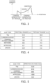
- the charge e is generated in a range from the position A at which the proton p and the tritium T were produced until the proton p and the tritium T stop. Because the masses and the energies are not equal between the proton p and the tritium T, the ranges from the position A at which the nuclear reaction occurred until stopping are different from each other. Therefore, as shown in FIG. 3 , the centroid of the charge e made by the proton p and the tritium T is shifted toward the proton p-side from the position A at which the nuclear reaction occurred. Accordingly, the position A at which the nuclear reaction occurred and the centroid of the charge e are shifted. Also, the directions in which the proton p and the tritium T travel are random.
- the centroid of the charge e created in the gas 23 is not at one point, but is spread over a range having a correlation with the ranges of the proton p and the tritium T.
- the incident position of the neutron n is detected by determining the centroid of the charge e; therefore, the detection accuracy, i.e., the position resolution, of the incident position of the neutron n is affected more as the ranges of the proton p and the tritium T increase.
- the ratio of the output charge for the applied operating voltage decreases as the partial pressure of the added nitrogen increases, therefore making it necessary to apply a higher operating voltage to obtain the desired output charge.
- the table of FIG. 5 shows the relationship between the gas type and the operating voltage.
- nitrogen when added as the additive gas of the neutron position detector 11, nitrogen functions as a quenching gas but has a weak ability to reduce the ranges of the proton p and the tritium T; therefore, when the partial pressure of nitrogen is increased to reduce the ranges of the proton p and the tritium T, then the operating voltage undesirably increases. Accordingly, until now, nitrogen has not been applied to products as an additive gas of the neutron position detector 11.
- the additive gas includes nitrogen as a quenching gas and argon as a gas that reduces the ranges of the proton p and the tritium T that are reaction products of the neutron n and the 3 He gas.
- nitrogen is not used as quenching gas in the neutron position detector 11 as described above due to the lengths of the ranges of the proton p and the tritium T and/or the high operating voltage, the long life of nitrogen is an example of its advantages.
- the triple bond of the nitrogen molecule has the characteristic of being not easy to break because the bond energy is greater than those of the double bond of carbon dioxide and the single bond of carbon tetrafluoride.
- the partial pressure of nitrogen when using the neutron position detector 11 in practice, it is favorable for the partial pressure of nitrogen to have the relationship of d ⁇ pN2 > 0.03 (atm ⁇ cm), where d (cm) is the inner diameter of the enclosure 20, and pN2 (atm) is the partial pressure of nitrogen. It is necessary to increase the partial pressure of nitrogen when the inner diameter of the enclosure 20 is narrow because the ultraviolet rays must be absorbed within a short distance when the inner diameter is narrow. When the partial pressure of nitrogen is less than the partial pressure determined by the formula above, there is a possibility that the absorption of the ultraviolet rays may not be sufficient, the operation may become unstable, or discharge may occur at a low voltage.
- the applied voltage at which the same output charge is obtained is drastically different between argon and nitrogen. It can be seen from the table of FIG. 5 that when argon and nitrogen are added with the same partial pressure, the effect on the operating voltage of argon is about 1/3 of that of nitrogen. Accordingly, argon is superior to nitrogen as an additive gas for reducing the ranges of the proton p and the tritium T. That is, even when the partial pressure of argon is increased to reduce the ranges of the proton p and the tritium T, the effect on the operating voltage is small. In such a case, it is favorable for the relationship to be such that the partial pressure of argon is greater than the partial pressure of nitrogen to reduce the ranges of the proton p and the tritium T.
- the partial pressure of argon cannot be increased limitlessly because compared to nitrogen, argon has the disadvantage of having high sensitivity to gamma rays and having an effect on the operating voltage that is not completely negligible.
- the ranges of the proton p and the tritium T decrease as the partial pressure of argon increases, the position resolution of the neutron position detector 11 is not determined only by the ranges of the proton p and the tritium T, and is also affected by thermal noise of the electrical circuit system and the S/N ratios of the preamplifiers; and the position resolution is not limitlessly improved only by increasing the partial pressure of argon.
- the pressure of argon is too low, the ranges of the proton p and the tritium T are not reduced, and the position resolution that is important in the neutron position detector 11 is not improved.
- the partial pressure of argon has an appropriate range that is favorably 1 to 3 atm.
- the total of the ranges of the proton p and the tritium T is substantially inversely proportional to the pressure and is 13 mm at 1 atm of argon and 4.3 mm at 3 atm.
- the position resolution is in the range of 4 mm to 20 mm; and setting argon to 1 to 3 atm would actually realize a significant improvement of the position resolution.
- the ranges of the proton p and the tritium T are reduced by setting the partial pressure of argon to be greater than this range, other factors (the thermal noise of the electrical circuit, etc.) prevail, the position resolution is not improved, the gamma ray sensitivity is increased, the operating voltage is increased, and only disadvantages become pronounced.
- the subdivision of argon is less than this range, the effect of adding argon is small, and the obtained advantages are meager.
- the additive gas includes nitrogen as a quenching gas and argon as a gas that reduces the ranges of the proton p and the tritium T that are reaction products of the neutron n and the 3 He gas, a longer life is possible while ensuring the position resolution, i.e., the detection accuracy of the incident position of the neutron n.
Landscapes
- Physics & Mathematics (AREA)
- Health & Medical Sciences (AREA)
- Life Sciences & Earth Sciences (AREA)
- General Physics & Mathematics (AREA)
- High Energy & Nuclear Physics (AREA)
- Molecular Biology (AREA)
- Spectroscopy & Molecular Physics (AREA)
- Measurement Of Radiation (AREA)
- Electron Tubes For Measurement (AREA)
Applications Claiming Priority (2)
| Application Number | Priority Date | Filing Date | Title |
|---|---|---|---|
| JP2020072928A JP7332527B2 (ja) | 2020-04-15 | 2020-04-15 | 中性子位置検出器 |
| PCT/JP2020/027636 WO2021210191A1 (fr) | 2020-04-15 | 2020-07-16 | Détecteur de position de neutrons |
Publications (3)
| Publication Number | Publication Date |
|---|---|
| EP4137847A1 true EP4137847A1 (fr) | 2023-02-22 |
| EP4137847A4 EP4137847A4 (fr) | 2024-05-08 |
| EP4137847B1 EP4137847B1 (fr) | 2025-04-09 |
Family
ID=78085101
Family Applications (1)
| Application Number | Title | Priority Date | Filing Date |
|---|---|---|---|
| EP20931456.6A Active EP4137847B1 (fr) | 2020-04-15 | 2020-07-16 | Détecteur de position de neutrons |
Country Status (5)
| Country | Link |
|---|---|
| US (1) | US11822027B2 (fr) |
| EP (1) | EP4137847B1 (fr) |
| JP (1) | JP7332527B2 (fr) |
| CN (1) | CN115398275B (fr) |
| WO (1) | WO2021210191A1 (fr) |
Families Citing this family (1)
| Publication number | Priority date | Publication date | Assignee | Title |
|---|---|---|---|---|
| EP4258301B1 (fr) * | 2022-04-08 | 2025-06-04 | Hitachi Energy Ltd | Enceinte |
Family Cites Families (14)
| Publication number | Priority date | Publication date | Assignee | Title |
|---|---|---|---|---|
| US3092747A (en) | 1959-01-09 | 1963-06-04 | Philips Corp | Proportional counter |
| JPH0239187U (fr) * | 1988-09-09 | 1990-03-15 | ||
| JP2003167062A (ja) * | 2001-12-03 | 2003-06-13 | Kansai Tlo Kk | 中性子位置検出器 |
| US7049603B2 (en) * | 2004-07-26 | 2006-05-23 | Temple University Of The Commonwealth System Of Higher Education | Neutron source detection camera |
| US7827822B2 (en) * | 2007-07-25 | 2010-11-09 | Schott Corporation | Method and apparatus for spray-forming melts of glass and glass-ceramic compositions |
| US20090188782A1 (en) * | 2007-10-01 | 2009-07-30 | Escrub Systems Incorporated | Wet-discharge electron beam flue gas scrubbing treatment |
| US8704189B2 (en) * | 2009-11-18 | 2014-04-22 | Saint-Gobain Ceramics & Plastics, Inc. | System and method for ionizing radiation detection |
| US20130119261A1 (en) | 2011-11-10 | 2013-05-16 | General Electric Company | Neutron detector and method for detecting neutrons |
| US9128191B2 (en) | 2012-12-17 | 2015-09-08 | General Electric Company | HE-3 detector guard band |
| JP2017142135A (ja) | 2016-02-09 | 2017-08-17 | 国立大学法人 東京大学 | 検出器、検出方法およびガラス基板 |
| RU2633867C1 (ru) * | 2017-01-09 | 2017-10-18 | федеральное государственное бюджетное образовательное учреждение высшего образования "Уфимский государственный авиационный технический университет" | Способ низкотемпературного ионного азотирования титановых сплавов |
| JP6228340B1 (ja) * | 2017-05-15 | 2017-11-08 | 東芝電子管デバイス株式会社 | 中性子位置検出器 |
| CN109384806B (zh) * | 2017-08-03 | 2021-04-27 | 王璐 | 一种[18f]fbpa新型制备方法 |
| JP6985206B2 (ja) | 2018-04-18 | 2021-12-22 | キヤノン電子管デバイス株式会社 | 放射線位置検出器 |
-
2020
- 2020-04-15 JP JP2020072928A patent/JP7332527B2/ja active Active
- 2020-07-16 EP EP20931456.6A patent/EP4137847B1/fr active Active
- 2020-07-16 CN CN202080099808.3A patent/CN115398275B/zh active Active
- 2020-07-16 WO PCT/JP2020/027636 patent/WO2021210191A1/fr not_active Ceased
-
2022
- 2022-10-03 US US17/937,470 patent/US11822027B2/en active Active
Also Published As
| Publication number | Publication date |
|---|---|
| CN115398275A (zh) | 2022-11-25 |
| EP4137847A4 (fr) | 2024-05-08 |
| US20230110535A1 (en) | 2023-04-13 |
| WO2021210191A1 (fr) | 2021-10-21 |
| JP2021169956A (ja) | 2021-10-28 |
| US11822027B2 (en) | 2023-11-21 |
| JP7332527B2 (ja) | 2023-08-23 |
| EP4137847B1 (fr) | 2025-04-09 |
| CN115398275B (zh) | 2025-12-16 |
Similar Documents
| Publication | Publication Date | Title |
|---|---|---|
| Peskov et al. | The study and optimization of new micropattern gaseous detectors for high-rate applications | |
| US11822027B2 (en) | Neutron position detector | |
| Bencivenni et al. | Performance of a triple-GEM detector for high rate charged particle triggering | |
| CN106783502B (zh) | 一种同步辐射软x射线无损实时位置分辨电离室 | |
| US3300640A (en) | Means for measuring plasma density by resonant charge transfer with a beam of neutral particles | |
| JP6985206B2 (ja) | 放射線位置検出器 | |
| Schildkamp et al. | Position monitor and readout electronics for undulator and focused bending magnet beamlines | |
| CN101371162A (zh) | 比例计数管 | |
| Melnik et al. | Bench tests of a helium ion source for the neutral particle diagnostic system of the ITER tokamak | |
| US4091288A (en) | Threshold self-powered gamma detector for use as a monitor of power in a nuclear reactor | |
| Bass et al. | Symmetrical two-crystal compton polarimeter for gamma rays | |
| Smith | High accuracy gaseous x-ray detectors | |
| Ebert et al. | Vacuum Diode Detector for Measuring High Intensity Gamma‐Ray Flux | |
| US10126441B1 (en) | Neutron position detector | |
| Suzuki et al. | Apparatus for positron-annihilation-induced Auger electron spectroscopy with a pulsed positron beam | |
| Melchart et al. | The multistep avalanche chamber as a detector for thermal neutrons | |
| Harris et al. | Angular localisation of proportional chamber avalanche | |
| JP2019078653A (ja) | 中性子位置検出器および中性子位置検出装置 | |
| Zhang et al. | A two-dimensional neutron detector assembly at the China Mianyang Research Reactor | |
| Takeda et al. | Neutron response functions improved by taking into consideration the measured edge effect of the/sup 3/He proportional counter | |
| Sherman et al. | H-beam neutralization measurements with a gridded-energy analyzer, a noninterceptive beam diagnostic | |
| Werle et al. | Investigation of the specific energy loss of protons in hydrogen above 1 keV with regard to neutron spectrometry | |
| Culhane et al. | Circuits for pulse rise time discrimination in proportional counters | |
| Coimbra et al. | First results with THGEM followed by submillimetric multiplying gap | |
| Krist et al. | Precision measurements of energy losses of He-ions in thin carbon foils |
Legal Events
| Date | Code | Title | Description |
|---|---|---|---|
| STAA | Information on the status of an ep patent application or granted ep patent |
Free format text: STATUS: THE INTERNATIONAL PUBLICATION HAS BEEN MADE |
|
| PUAI | Public reference made under article 153(3) epc to a published international application that has entered the european phase |
Free format text: ORIGINAL CODE: 0009012 |
|
| STAA | Information on the status of an ep patent application or granted ep patent |
Free format text: STATUS: REQUEST FOR EXAMINATION WAS MADE |
|
| 17P | Request for examination filed |
Effective date: 20220923 |
|
| AK | Designated contracting states |
Kind code of ref document: A1 Designated state(s): AL AT BE BG CH CY CZ DE DK EE ES FI FR GB GR HR HU IE IS IT LI LT LU LV MC MK MT NL NO PL PT RO RS SE SI SK SM TR |
|
| DAV | Request for validation of the european patent (deleted) | ||
| DAX | Request for extension of the european patent (deleted) | ||
| A4 | Supplementary search report drawn up and despatched |
Effective date: 20240410 |
|
| RIC1 | Information provided on ipc code assigned before grant |
Ipc: H01J 47/12 20060101ALI20240404BHEP Ipc: H01J 47/06 20060101ALI20240404BHEP Ipc: G01T 3/00 20060101AFI20240404BHEP |
|
| GRAP | Despatch of communication of intention to grant a patent |
Free format text: ORIGINAL CODE: EPIDOSNIGR1 |
|
| STAA | Information on the status of an ep patent application or granted ep patent |
Free format text: STATUS: GRANT OF PATENT IS INTENDED |
|
| INTG | Intention to grant announced |
Effective date: 20241030 |
|
| GRAS | Grant fee paid |
Free format text: ORIGINAL CODE: EPIDOSNIGR3 |
|
| GRAA | (expected) grant |
Free format text: ORIGINAL CODE: 0009210 |
|
| STAA | Information on the status of an ep patent application or granted ep patent |
Free format text: STATUS: THE PATENT HAS BEEN GRANTED |
|
| AK | Designated contracting states |
Kind code of ref document: B1 Designated state(s): AL AT BE BG CH CY CZ DE DK EE ES FI FR GB GR HR HU IE IS IT LI LT LU LV MC MK MT NL NO PL PT RO RS SE SI SK SM TR |
|
| REG | Reference to a national code |
Ref country code: GB Ref legal event code: FG4D |
|
| REG | Reference to a national code |
Ref country code: CH Ref legal event code: EP |
|
| REG | Reference to a national code |
Ref country code: DE Ref legal event code: R096 Ref document number: 602020049352 Country of ref document: DE |
|
| REG | Reference to a national code |
Ref country code: IE Ref legal event code: FG4D |
|
| PGFP | Annual fee paid to national office [announced via postgrant information from national office to epo] |
Ref country code: FR Payment date: 20250523 Year of fee payment: 6 |
|
| REG | Reference to a national code |
Ref country code: NL Ref legal event code: MP Effective date: 20250409 |
|
| PG25 | Lapsed in a contracting state [announced via postgrant information from national office to epo] |
Ref country code: NL Free format text: LAPSE BECAUSE OF FAILURE TO SUBMIT A TRANSLATION OF THE DESCRIPTION OR TO PAY THE FEE WITHIN THE PRESCRIBED TIME-LIMIT Effective date: 20250409 |
|
| REG | Reference to a national code |
Ref country code: AT Ref legal event code: MK05 Ref document number: 1784003 Country of ref document: AT Kind code of ref document: T Effective date: 20250409 |
|
| PG25 | Lapsed in a contracting state [announced via postgrant information from national office to epo] |
Ref country code: PT Free format text: LAPSE BECAUSE OF FAILURE TO SUBMIT A TRANSLATION OF THE DESCRIPTION OR TO PAY THE FEE WITHIN THE PRESCRIBED TIME-LIMIT Effective date: 20250811 Ref country code: ES Free format text: LAPSE BECAUSE OF FAILURE TO SUBMIT A TRANSLATION OF THE DESCRIPTION OR TO PAY THE FEE WITHIN THE PRESCRIBED TIME-LIMIT Effective date: 20250409 Ref country code: FI Free format text: LAPSE BECAUSE OF FAILURE TO SUBMIT A TRANSLATION OF THE DESCRIPTION OR TO PAY THE FEE WITHIN THE PRESCRIBED TIME-LIMIT Effective date: 20250409 |
|
| PGFP | Annual fee paid to national office [announced via postgrant information from national office to epo] |
Ref country code: DE Payment date: 20250528 Year of fee payment: 6 |
|
| REG | Reference to a national code |
Ref country code: LT Ref legal event code: MG9D |
|
| PG25 | Lapsed in a contracting state [announced via postgrant information from national office to epo] |
Ref country code: NO Free format text: LAPSE BECAUSE OF FAILURE TO SUBMIT A TRANSLATION OF THE DESCRIPTION OR TO PAY THE FEE WITHIN THE PRESCRIBED TIME-LIMIT Effective date: 20250709 Ref country code: GR Free format text: LAPSE BECAUSE OF FAILURE TO SUBMIT A TRANSLATION OF THE DESCRIPTION OR TO PAY THE FEE WITHIN THE PRESCRIBED TIME-LIMIT Effective date: 20250710 |
|
| PG25 | Lapsed in a contracting state [announced via postgrant information from national office to epo] |
Ref country code: PL Free format text: LAPSE BECAUSE OF FAILURE TO SUBMIT A TRANSLATION OF THE DESCRIPTION OR TO PAY THE FEE WITHIN THE PRESCRIBED TIME-LIMIT Effective date: 20250409 |
|
| PG25 | Lapsed in a contracting state [announced via postgrant information from national office to epo] |
Ref country code: BG Free format text: LAPSE BECAUSE OF FAILURE TO SUBMIT A TRANSLATION OF THE DESCRIPTION OR TO PAY THE FEE WITHIN THE PRESCRIBED TIME-LIMIT Effective date: 20250409 |
|
| PG25 | Lapsed in a contracting state [announced via postgrant information from national office to epo] |
Ref country code: HR Free format text: LAPSE BECAUSE OF FAILURE TO SUBMIT A TRANSLATION OF THE DESCRIPTION OR TO PAY THE FEE WITHIN THE PRESCRIBED TIME-LIMIT Effective date: 20250409 |
|
| PG25 | Lapsed in a contracting state [announced via postgrant information from national office to epo] |
Ref country code: AT Free format text: LAPSE BECAUSE OF FAILURE TO SUBMIT A TRANSLATION OF THE DESCRIPTION OR TO PAY THE FEE WITHIN THE PRESCRIBED TIME-LIMIT Effective date: 20250409 |
|
| PG25 | Lapsed in a contracting state [announced via postgrant information from national office to epo] |
Ref country code: RS Free format text: LAPSE BECAUSE OF FAILURE TO SUBMIT A TRANSLATION OF THE DESCRIPTION OR TO PAY THE FEE WITHIN THE PRESCRIBED TIME-LIMIT Effective date: 20250709 |
|
| PG25 | Lapsed in a contracting state [announced via postgrant information from national office to epo] |
Ref country code: IS Free format text: LAPSE BECAUSE OF FAILURE TO SUBMIT A TRANSLATION OF THE DESCRIPTION OR TO PAY THE FEE WITHIN THE PRESCRIBED TIME-LIMIT Effective date: 20250809 |
|
| PG25 | Lapsed in a contracting state [announced via postgrant information from national office to epo] |
Ref country code: LV Free format text: LAPSE BECAUSE OF FAILURE TO SUBMIT A TRANSLATION OF THE DESCRIPTION OR TO PAY THE FEE WITHIN THE PRESCRIBED TIME-LIMIT Effective date: 20250409 |
|
| REG | Reference to a national code |
Ref country code: DE Ref legal event code: R097 Ref document number: 602020049352 Country of ref document: DE |
|
| PG25 | Lapsed in a contracting state [announced via postgrant information from national office to epo] |
Ref country code: SM Free format text: LAPSE BECAUSE OF FAILURE TO SUBMIT A TRANSLATION OF THE DESCRIPTION OR TO PAY THE FEE WITHIN THE PRESCRIBED TIME-LIMIT Effective date: 20250409 Ref country code: DK Free format text: LAPSE BECAUSE OF FAILURE TO SUBMIT A TRANSLATION OF THE DESCRIPTION OR TO PAY THE FEE WITHIN THE PRESCRIBED TIME-LIMIT Effective date: 20250409 |
|
| PG25 | Lapsed in a contracting state [announced via postgrant information from national office to epo] |
Ref country code: CZ Free format text: LAPSE BECAUSE OF FAILURE TO SUBMIT A TRANSLATION OF THE DESCRIPTION OR TO PAY THE FEE WITHIN THE PRESCRIBED TIME-LIMIT Effective date: 20250409 |
|
| PG25 | Lapsed in a contracting state [announced via postgrant information from national office to epo] |
Ref country code: EE Free format text: LAPSE BECAUSE OF FAILURE TO SUBMIT A TRANSLATION OF THE DESCRIPTION OR TO PAY THE FEE WITHIN THE PRESCRIBED TIME-LIMIT Effective date: 20250409 |
|
| PG25 | Lapsed in a contracting state [announced via postgrant information from national office to epo] |
Ref country code: SK Free format text: LAPSE BECAUSE OF FAILURE TO SUBMIT A TRANSLATION OF THE DESCRIPTION OR TO PAY THE FEE WITHIN THE PRESCRIBED TIME-LIMIT Effective date: 20250409 |
|
| PG25 | Lapsed in a contracting state [announced via postgrant information from national office to epo] |
Ref country code: IT Free format text: LAPSE BECAUSE OF FAILURE TO SUBMIT A TRANSLATION OF THE DESCRIPTION OR TO PAY THE FEE WITHIN THE PRESCRIBED TIME-LIMIT Effective date: 20250409 |
|
| PG25 | Lapsed in a contracting state [announced via postgrant information from national office to epo] |
Ref country code: RO Free format text: LAPSE BECAUSE OF FAILURE TO SUBMIT A TRANSLATION OF THE DESCRIPTION OR TO PAY THE FEE WITHIN THE PRESCRIBED TIME-LIMIT Effective date: 20250409 |
|
| PLBE | No opposition filed within time limit |
Free format text: ORIGINAL CODE: 0009261 |
|
| STAA | Information on the status of an ep patent application or granted ep patent |
Free format text: STATUS: NO OPPOSITION FILED WITHIN TIME LIMIT |
|
| REG | Reference to a national code |
Ref country code: CH Ref legal event code: L10 Free format text: ST27 STATUS EVENT CODE: U-0-0-L10-L00 (AS PROVIDED BY THE NATIONAL OFFICE) Effective date: 20260218 |
|
| REG | Reference to a national code |
Ref country code: CH Ref legal event code: H13 Free format text: ST27 STATUS EVENT CODE: U-0-0-H10-H13 (AS PROVIDED BY THE NATIONAL OFFICE) Effective date: 20260224 |
|
| PG25 | Lapsed in a contracting state [announced via postgrant information from national office to epo] |
Ref country code: LU Free format text: LAPSE BECAUSE OF NON-PAYMENT OF DUE FEES Effective date: 20250716 |
|
| 26N | No opposition filed |
Effective date: 20260112 |
|
| GBPC | Gb: european patent ceased through non-payment of renewal fee |
Effective date: 20250716 |
|
| REG | Reference to a national code |
Ref country code: BE Ref legal event code: MM Effective date: 20250731 |
|
| PG25 | Lapsed in a contracting state [announced via postgrant information from national office to epo] |
Ref country code: GB Free format text: LAPSE BECAUSE OF NON-PAYMENT OF DUE FEES Effective date: 20250716 |
|
| PG25 | Lapsed in a contracting state [announced via postgrant information from national office to epo] |
Ref country code: BE Free format text: LAPSE BECAUSE OF NON-PAYMENT OF DUE FEES Effective date: 20250731 |
|
| PG25 | Lapsed in a contracting state [announced via postgrant information from national office to epo] |
Ref country code: CH Free format text: LAPSE BECAUSE OF NON-PAYMENT OF DUE FEES Effective date: 20250731 |