EP4137860B1 - Optische bildgebungslinse - Google Patents
Optische bildgebungslinse Download PDFInfo
- Publication number
- EP4137860B1 EP4137860B1 EP21205239.3A EP21205239A EP4137860B1 EP 4137860 B1 EP4137860 B1 EP 4137860B1 EP 21205239 A EP21205239 A EP 21205239A EP 4137860 B1 EP4137860 B1 EP 4137860B1
- Authority
- EP
- European Patent Office
- Prior art keywords
- lens
- optical imaging
- focal length
- imaging lens
- image
- Prior art date
- Legal status (The legal status is an assumption and is not a legal conclusion. Google has not performed a legal analysis and makes no representation as to the accuracy of the status listed.)
- Active
Links
Images





Classifications
-
- G—PHYSICS
- G02—OPTICS
- G02B—OPTICAL ELEMENTS, SYSTEMS OR APPARATUS
- G02B13/00—Optical objectives specially designed for the purposes specified below
- G02B13/04—Reversed telephoto objectives
-
- G—PHYSICS
- G02—OPTICS
- G02B—OPTICAL ELEMENTS, SYSTEMS OR APPARATUS
- G02B13/00—Optical objectives specially designed for the purposes specified below
- G02B13/001—Miniaturised objectives for electronic devices, e.g. portable telephones, webcams, PDAs, small digital cameras
- G02B13/0015—Miniaturised objectives for electronic devices, e.g. portable telephones, webcams, PDAs, small digital cameras characterised by the lens design
- G02B13/002—Miniaturised objectives for electronic devices, e.g. portable telephones, webcams, PDAs, small digital cameras characterised by the lens design having at least one aspherical surface
- G02B13/0045—Miniaturised objectives for electronic devices, e.g. portable telephones, webcams, PDAs, small digital cameras characterised by the lens design having at least one aspherical surface having five or more lenses
-
- G—PHYSICS
- G02—OPTICS
- G02B—OPTICAL ELEMENTS, SYSTEMS OR APPARATUS
- G02B13/00—Optical objectives specially designed for the purposes specified below
- G02B13/06—Panoramic objectives; So-called "sky lenses" including panoramic objectives having reflecting surfaces
-
- G—PHYSICS
- G02—OPTICS
- G02B—OPTICAL ELEMENTS, SYSTEMS OR APPARATUS
- G02B9/00—Optical objectives characterised both by the number of the components and their arrangements according to their sign, i.e. + or -
- G02B9/62—Optical objectives characterised both by the number of the components and their arrangements according to their sign, i.e. + or - having six components only
Definitions
- the present invention generally relates to an optical image capturing system, and more particularly to an optical imaging lens, which provides a better optical performance of high image quality and low distortion.
- the image sensing device of the ordinary photographing camera is commonly selected from a charge-coupled device (CCD) or a complementary metal-oxide-semiconductor sensor (CMOS Sensor).
- CCD charge-coupled device
- CMOS Sensor complementary metal-oxide-semiconductor sensor
- ADAS Advanced Driver Assistance System
- the primary objective of the present invention is to provide an optical imaging lens that provides a better optical performance of high image quality and low distortion.
- an optical imaging lens according to claim 1 is provided.
- Examples of such optical imaging lens are defined in dependent claims 2-25.
- the present invention provides an optical imaging lens, in order from an object side to an image side along an optical axis, including a first optical assembly having negative refractive power, a second optical assembly having negative refractive power, a third optical assembly having positive refractive power, an aperture, a fourth optical assembly having positive refractive power, a fifth optical assembly having positive refractive power, and a sixth optical assembly having positive refractive power, wherein two of the first optical assembly, the second optical assembly, the third optical assembly, the fourth optical assembly, the fifth optical assembly, and the sixth optical assembly include a compound lens formed by adhering at least two lenses.
- the present invention further provides an optical imaging lens, in order from an object side to an image side along an optical axis, includes a first lens having negative refractive power, a second lens having negative refractive power, a third lens having positive refractive power, an aperture, a fourth lens having positive refractive power, a fifth lens having negative refractive power, a sixth lens having negative refractive power, a seventh lens having positive refractive power, and an eighth lens.
- An object-side surface of the first lens is a convex surface
- an image-side surface of the first lens is a concave surface.
- An object-side surface of the second lens is a concave surface, and an image-side surface of the second lens is a convex surface.
- the eighth lens is a biconvex lens with positive refractive power.
- the arrangement of the refractive powers and the conditions of the optical imaging lens of the present invention could achieve the effect of high image quality and low distortion and could also meet the imaging requirement of visible light during the day and infrared light at night.
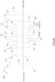
- FIG. 1A An optical imaging lens 100 according to a first embodiment of the present invention is illustrated in FIG. 1A , which includes, in order along an optical axis Z from an object side to an image side, a first optical assembly C1, a second optical assembly C2, a third optical assembly C3, an aperture ST, a fourth optical assembly C4, a fifth optical assembly C5, and a sixth optical assembly C6.
- two of the first optical assembly, the second optical assembly, the third optical assembly, the fourth optical assembly, the fifth optical assembly, and the sixth optical assembly include a compound lens with at least two lenses that are adhered, while the others are single lens.
- the first optical assembly C1 has negative refractive power.
- the first optical assembly C1 is a single lens that includes a first lens L1, wherein an object-side surface S1 of the first lens L1 is a convex surface toward the object side, and an image-side surface S2 of the first lens L1 is a concave surface that is arc-shaped. As shown in FIG. 1A , a part of a surface of the first lens L1 toward the image side is recessed to form the image-side surface S2, and the optical axis Z passes through the object-side surface S1 and the image-side surface S2.
- the second optical assembly C2 has negative refractive power.
- the second optical assembly C2 is a single lens that includes a second lens L2, wherein the second lens L2 is a negative meniscus.
- an object-side surface S3 of the second lens L2 is a concave surface that is arc-shaped and recessed toward the image side
- an image-side surface S4 of the second lens L2 is a convex surface toward the image side
- the optical axis Z passes through the object-side surface S3 and the image-side surface S4.
- the third optical assembly C3 has positive refractive power.
- the third optical assembly C3 is a single lens that includes a third lens L3, wherein the third lens L3 is a biconvex lens (i.e., both of an object-side surface S5 of the third lens L3 and an image-side surface S6 of the third lens L3 are convex surfaces).
- the object-side surface S5 of the third lens L3 is convex toward the object side in an arc shape
- the image-side surface S6 of the third lens L3 is slightly convex toward the image side.
- the fourth optical assembly C4 has positive refractive power.
- the fourth optical assembly C4 is a compound lens formed by adhering a fourth lens L4 and a fifth lens L5, which could effectively improve a chromatic aberration of the optical imaging lens 100.
- the fourth lens is a biconvex lens (i.e., both of an object-side surface S7 of the fourth lens L4 and an image-side surface S8 of the fourth lens L4 are convex surfaces) with positive refractive power, wherein the aperture ST is located between the object-side surface S7 of the fourth lens L4 and the image-side surface S6 of the third lens L3, which reduces the stray light and therefore enhances the image quality.
- the fifth lens L5 is a negative meniscus with negative refractive power, wherein an object-side surface S9 of the fifth lens L5 is a concave surface that is recessed toward the image side in an arc shape, and an image-side surface S10 of the fifth lens L5 is a convex surface toward the image side.
- the object-side surface S9 of the fifth lens L5 and the image-side surface S8 of the fourth lens L4 are adhered and form a same surface.
- the fifth optical assembly C5 has positive refractive power.
- the fifth optical assembly C5 is a compound lens formed by adhering a sixth lens L6 and a seventh lens L7, which could effectively improve a chromatic aberration of the optical imaging lens 100.
- the sixth lens L6 is a negative meniscus with negative refractive power, wherein an object-side surface S11 of the sixth lens L6 is a convex surface toward the object side in an arc shape, and an image-side surface S12 of the sixth lens L6 is a concave surface that is recessed toward the object side.
- the seventh lens L7 is a positive meniscus with positive refractive power, wherein an object-side surface S13 of the seventh lens L7 is a convex surface toward the object side in an arc shape, and an image-side surface S14 of the seventh lens L7 is a concave surface that is recessed toward the object side in an arc shape.
- the object-side surface S13 of the seventh lens L7 and the image-side surface S12 of the sixth lens L6 are adhered and form a same surface.
- the sixth optical assembly C6 has positive refractive power.
- the sixth optical assembly C6 is a single lens that includes an eighth lens L8, wherein the eighth lens L8 is a biconvex lens (i.e., both of an object-side surface S15 of the eighth lens L8 and an image-side surface S16 of the eighth lens L8 are convex surfaces), and both of the object-side surface S15 and the image-side surface S16 of the eighth lens L8 are aspheric surfaces.
- the optical imaging lens 100 further includes an infrared filter L9 and a protective glass L10, wherein the infrared filter L9 is disposed between the eighth lens L8 and the protective glass L10 and is closer to the image-side surface S16 of the eighth lens L8 than the protective glass L10.
- the protective glass L10 for protecting the infrared filter L9 is disposed between the infrared filter L9 and an image plane Im of the optical imaging lens 100 and is closer to the image plane Im than the infrared filter L9.
- the optical imaging lens 100 further satisfies: ⁇ 0.5 > F / f1 > ⁇ 0.7 ; ⁇ 0.15 > F / f2 > ⁇ 0.3 ; 0.4 > F / f3 > 0.2 ; 0.3 > F/f45 > 0.15 ; 0 .15 > F / f4 > 0.05 ; ⁇ 0.01 > F / f5 > ⁇ 0.03 ; 0.15 > F/f67 > 0.002 ; ⁇ 0 .10 > F / f6 > ⁇ 0.20 ; 0.6 > F / f7 > 0.4 ; 0.3 > F / f8 > 0.15 ; wherein F is a focal length of the optical imaging lens 100; f1 is a focal length of the first lens L1 of the first optical assembly C1; f2 is a focal length of the second lens L2 of the second optical assembly C2; f3 is a focal length of the first lens L1 of the first optical assembly C1; f
- Parameters of the optical imaging lens 100 of the first embodiment of the present invention are listed in following Table 1, including the focal length F of the optical imaging lens 100 (also called an effective focal length (EFL)), a F-number (Fno), a maximal field of view (HFOV), a radius of curvature (R) of each lens, a distance (D) between each surface and the next surface on the optical axis Z, a refractive index (Nd) of each lens, the focal length of each lens, the focal length (cemented focal length) of the fourth optical assembly C4, and the focal length (cemented focal length) of the fifth optical assembly C5, wherein a unit of the focal length, the radius of curvature, and the distance is millimeter (mm).
- the first optical assembly C1 to the sixth optical assembly C6 satisfy the aforementioned conditions (1) to (6) of the optical imaging lens 100.
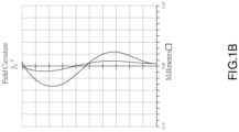
- FIG. 1B a diagram showing the astigmatic field curves according to the first embodiment
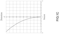
- FIG. 1C is a diagram showing the distortion according to the first embodiment
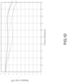
- FIG. 1D is a diagram showing the modulus of the OTF according to the first embodiment.
- a curve S is data of a sagittal direction
- a curve T is data of a tangential direction.
- the graphics shown in FIG. 1C and FIG. 1D are within a standard range. In this way, the optical imaging lens 100 of the first embodiment could effectively enhance image quality and lower a distortion thereof and could also meet the imaging requirement of visible light during the day and infrared light at night.
- FIG. 2A An optical imaging lens 200 according to a second embodiment of the present invention is illustrated in FIG. 2A , which includes, in order along an optical axis Z from an object side to an image side, a first optical assembly C1, a second optical assembly C2, a third optical assembly C3, an aperture ST, a fourth optical assembly C4, a fifth optical assembly C5, and a sixth optical assembly C6.
- the first optical assembly C1 has negative refractive power.
- the first optical assembly C1 is a single lens that includes a first lens L1, wherein an object-side surface S1 of the first lens L1 is a convex surface toward the object side, and an image-side surface S2 of the first lens L1 is a concave surface that is arc-shaped. As shown in FIG. 2A , a part of a surface of the first lens L1 toward the image side is recessed to form the image-side surface S2, and the optical axis Z passes through the object-side surface S1 and the image-side surface S2.
- the second optical assembly C2 has negative refractive power.
- the second optical assembly C2 is a single lens that includes a second lens L2, wherein the second lens L2 is a negative meniscus.
- an object-side surface S3 of the second lens L2 is a concave surface that is arc-shaped and recessed toward the image side
- an image-side surface S4 of the second lens L2 is a convex surface toward the image side
- the optical axis Z passes through the object-side surface S3 and the image-side surface S4.
- the third optical assembly C3 has positive refractive power.
- the third optical assembly C3 is a single lens that includes a third lens L3, wherein the third lens L3 is a biconvex lens (i.e., both of an object-side surface S5 of the third lens L3 and an image-side surface S6 of the third lens L3 are convex surfaces).
- the object-side surface S5 of the third lens L3 is convex toward the object side in an arc shape
- the image-side surface S6 of the third lens L3 is slightly convex toward the image side.
- the fourth optical assembly C4 has positive refractive power.
- the fourth optical assembly C4 is a compound lens formed by adhering a fourth lens L4 and a fifth lens L5, which could effectively improve a chromatic aberration of the optical imaging lens 200.
- the fourth lens is a biconvex lens (i.e., both of an object-side surface S7 of the fourth lens L4 and an image-side surface S8 of the fourth lens L4 are convex surfaces) with positive refractive power, wherein the aperture ST is located between the object-side surface S7 of the fourth lens L4 and the image-side surface S6 of the third lens L3, which reduces the stray light and therefore enhances the image quality.
- the fifth lens L5 is a negative meniscus with negative refractive power, wherein an object-side surface S9 of the fifth lens L5 is a concave surface that is recessed toward the image side in an arc shape, and an image-side surface S10 of the fifth lens L5 is a convex surface toward the image side.
- the object-side surface S9 of the fifth lens L5 and the image-side surface S8 of the fourth lens L4 are adhered and form a same surface.
- the fifth optical assembly C5 has positive refractive power.
- the fifth optical assembly C5 is a compound lens formed by adhering a sixth lens L6 and a seventh lens L7, which could effectively improve a chromatic aberration of the optical imaging lens 200.
- the sixth lens L6 is a negative meniscus with negative refractive power, wherein an object-side surface S11 of the sixth lens L6 is a convex surface toward the object side in an arc shape, and an image-side surface S12 of the sixth lens L6 is a concave surface that is recessed toward the object side in an arc shape.
- the seventh lens L7 is a positive meniscus with positive refractive power, wherein an object-side surface S13 of the seventh lens L7 is a convex surface toward the object side in an arc shape, and an image-side surface S14 of the seventh lens L7 is a concave surface that is recessed toward the object side in an arc shape.
- the object-side surface S13 of the seventh lens L7 and the image-side surface S12 of the sixth lens L6 are adhered and form a same surface.
- the sixth optical assembly C6 has positive refractive power.
- the sixth optical assembly C6 is a single lens that includes an eighth lens L8, wherein the eighth lens L8 is a biconvex lens (i.e., both of an object-side surface S15 of the eighth lens L8 and an image-side surface S16 of the eighth lens L8 are convex surfaces), and both of the obj ect-side surface S15 and the image-side surface S16 of the eighth lens L8 are aspheric surfaces.
- the optical imaging lens 200 further includes an infrared filter L9 and a protective glass L10, wherein the infrared filter L9 is disposed between the eighth lens L8 and the protective glass L10 and is closer to the image-side surface S16 of the eighth lens L8 than the protective glass L10.
- the protective glass L10 for protecting the infrared filter L9 is disposed between the infrared filter L9 and an image plane Im of the optical imaging lens 200 and is closer to the image plane Im than the infrared filter L9.
- the optical imaging lens 200 further satisfies: ⁇ 0.5 > F / f1 > ⁇ 0.7 ; ⁇ 0.15 > F / f2 > ⁇ 0.3 ; 0.4 > F / f3 > 0.2 ; 0.3 > F/f45 > 0.15 ; 0 .15 > F/f4 > 0.05 ; ⁇ 0.01 > F/f5 > ⁇ 0.03 ; 0.15 > F/f67 > 0.002 ; ⁇ 0.10 > F/f6 > ⁇ 0.20 ; 0 .6 > F/f7 > 0.4 ; 0.3 > F / f8 > 0.15 ; wherein F is a focal length of the optical imaging lens 200; f1 is a focal length of the first lens L1 of the first optical assembly C1; f2 is a focal length of the second lens L2 of the second optical assembly C2; f3 is a focal length of the third lens L3 of
- Parameters of the optical imaging lens 200 of the second embodiment of the present invention are listed in following Table 3, including the focal length F of the optical imaging lens 200 (also called an effective focal length (EFL)), a F-number (Fno), a maximal field of view (HFOV), a radius of curvature (R) of each lens, a distance (D) between each surface and the next surface on the optical axis Z, a refractive index (Nd) of each lens, the focal length of each lens, the focal length (cemented focal length) of the fourth optical assembly C4, and the focal length (cemented focal length) of the fifth optical assembly C5, wherein a unit of the focal length, the radius of curvature, and the distance is millimeter (mm).
- the first optical assembly C1 to the sixth optical assembly C6 satisfy the aforementioned conditions (1) to (6) of the optical imaging lens 200.
- FIG. 2B a diagram showing the astigmatic field curves according to the second embodiment
- FIG. 2C is a diagram showing the distortion according to the second embodiment
- FIG. 2D is a diagram showing the modulus of the OTF according to the second embodiment.
- a curve S is data of a sagittal direction
- a curve T is data of a tangential direction.
- the graphics shown in FIG. 2C and FIG. 2D are within a standard range. In this way, the optical imaging lens 200 of the second embodiment could effectively enhance image quality and lower a distortion thereof and could also meet the imaging requirement of visible light during the day and infrared light at night.
- FIG. 3A An optical imaging lens 300 according to a third embodiment of the present invention is illustrated in FIG. 3A , which includes, in order along an optical axis Z from an object side to an image side, a first optical assembly C1, a second optical assembly C2, a third optical assembly C3, an aperture ST, a fourth optical assembly C4, a fifth optical assembly C5, and a sixth optical assembly C6.
- the first optical assembly C1 has negative refractive power.
- the first optical assembly C1 is a single lens that includes a first lens L1, wherein an object-side surface S1 of the first lens L1 is a convex surface toward the object side, and an image-side surface S2 of the first lens L1 is a concave surface that is arc-shaped. As shown in FIG. 3A , a part of a surface of the first lens L1 toward the image side is recessed to form the image-side surface S2, and the optical axis Z passes through the object-side surface S1 and the image-side surface S2.
- the second optical assembly C2 has negative refractive power.
- the second optical assembly C2 is a single lens that includes a second lens L2, wherein the second lens L2 is a negative meniscus.
- an object-side surface S3 of the second lens L2 is a concave surface that is arc-shaped and recessed toward the image side
- an image-side surface S4 of the second lens L2 is a convex surface toward the image side
- the optical axis Z passes through the object-side surface S3 and the image-side surface S4.
- the third optical assembly C3 has positive refractive power.
- the third optical assembly C3 is a single lens that includes a third lens L3, wherein the third lens L3 is a biconvex lens (i.e., both of an object-side surface S5 of the third lens L3 and an image-side surface S6 of the third lens L3 are convex surfaces).
- the object-side surface S5 of the third lens L3 is convex toward the object side in an arc shape
- the image-side surface S6 of the third lens L3 is slightly convex toward the image side.
- the fourth optical assembly C4 has positive refractive power.
- the fourth optical assembly C4 is a compound lens formed by adhering a fourth lens L4 and a fifth lens L5, which could effectively improve a chromatic aberration of the optical imaging lens 300.
- the fourth lens L4 is a biconvex lens (i.e., both of an object-side surface S7 of the fourth lens L4 and an image-side surface S8 of the fourth lens L4 are convex surfaces) with positive refractive power, wherein the aperture ST is located between the object-side surface S7 of the fourth lens L4 and the image-side surface S6 of the third lens L3, which reduces the stray light and therefore enhances the image quality.
- the fifth lens L5 is a negative meniscus with negative refractive power, wherein an object-side surface S9 of the fifth lens L5 is a concave surface that is recessed toward the image side in an arc shape, and an image-side surface S10 of the fifth lens L5 is a convex surface toward the image side.
- the object-side surface S9 of the fifth lens L5 and the image-side surface S8 of the fourth lens L4 are adhered and form a same surface.
- the fifth optical assembly C5 has positive refractive power.
- the fifth optical assembly C5 is a compound lens formed by adhering a sixth lens L6 and a seventh lens L7, which could effectively improve a chromatic aberration of the optical imaging lens 300.
- the sixth lens L6 is a negative meniscus with negative refractive power, wherein an object-side surface S11 of the sixth lens L6 is a convex surface toward the object side in an arc shape, and an image-side surface S12 of the sixth lens L6 is a concave surface that is recessed toward the object side.
- the seventh lens L7 is a positive meniscus with positive refractive power, wherein an object-side surface S13 of the seventh lens L7 is a convex surface toward the object side in an arc shape, and an image-side surface S14 of the seventh lens L7 is a concave surface that is recessed toward the object side in an arc shape.
- the object-side surface S13 of the seventh lens L7 and the image-side surface S12 of the sixth lens L6 are adhered and form a same surface.
- the sixth optical assembly C6 has positive refractive power.
- the sixth optical assembly C6 is a single lens that includes an eighth lens L8, wherein the eighth lens L8 is a biconvex lens (i.e., both of an object-side surface S15 of the eighth lens L8 and an image-side surface S16 of the eighth lens L8 are convex surfaces), and both of the object-side surface S15 and the image-side surface S16 of the eighth lens L8 are aspheric surfaces.
- the optical imaging lens 300 further includes an infrared filter L9 and a protective glass L10, wherein the infrared filter L9 is disposed between the eighth lens L8 and the protective glass L10 and is closer to the image-side surface S16 of the eighth lens L8 than the protective glass L 10.
- the protective glass L 10 for protecting the infrared filter L9 is disposed between the infrared filter L9 and an image plane Im of the optical imaging lens 300 and is closer to the image plane Im than the infrared filter L9.
- the optical imaging lens 300 further satisfies: ⁇ 0.5 > F / f1 > ⁇ 0.7 ; ⁇ 0.15 > F / f2 > ⁇ 0.3 ; 0.4 > F / f3 > 0.2 ; 0.3 > F/f45 > 0.15 ; 0 .15 > F / f4 > 0.05 ; ⁇ 0.01 > F/f5 > ⁇ 0.03 ; 0.15 > F/f67 > 0.002 ; ⁇ 0.10 > F/f6 > ⁇ 0.20 ; 0 .6 > F / f7 > 0.4 ; 0.3 > F/f8 > 0.15 ; wherein F is a focal length of the optical imaging lens 300; f1 is a focal length of the first lens L1 of the first optical assembly C1; f2 is a focal length of the second lens L2 of the second optical assembly C2; f3 is a focal length of the third lens L
- Parameters of the optical imaging lens 300 of the third embodiment of the present invention are listed in following Table 5, including the focal length F of the optical imaging lens 300 (also called an effective focal length (EFL)), a F-number (Fno), a maximal field of view (HFOV), a radius of curvature (R) of each lens, a distance (D) between each surface and the next surface on the optical axis Z, a refractive index (Nd) of each lens, the focal length of each lens, the focal length (cemented focal length) of the fourth optical assembly C4, and the focal length (cemented focal length) of the fifth optical assembly C5, wherein a unit of the focal length, the radius of curvature, and the distance is millimeter (mm).
- the first optical assembly C1 to the sixth optical assembly C6 satisfy the aforementioned conditions (1) to (6) of the optical imaging lens 300.
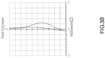
- FIG. 3B a diagram showing the astigmatic field curves according to the third embodiment
- FIG. 3C is a diagram showing the distortion according to the third embodiment
- FIG. 3D is a diagram showing the modulus of the OTF according to the third embodiment.
- a curve S is data of a sagittal direction
- a curve T is data of a tangential direction.
- the graphics shown in FIG. 3C and FIG. 3D are within a standard range. In this way, the optical imaging lens 300 of the third embodiment could effectively enhance image quality and lower a distortion thereof and could also meet the imaging requirement of visible light during the day and infrared light at night.
Landscapes
- Physics & Mathematics (AREA)
- General Physics & Mathematics (AREA)
- Optics & Photonics (AREA)
- Lenses (AREA)
- Lens Barrels (AREA)
- Glass Compositions (AREA)
- Aiming, Guidance, Guns With A Light Source, Armor, Camouflage, And Targets (AREA)
Claims (25)
- Optische Abbildungslinse (100, 200, 300), welche in der Reihenfolge von einer Objektseite aus hin zu einer Bildseite entlang einer optischen Achse (Z) aufweist:eine erste Linse (L1), welche eine negative Brechkraft hat;eine zweite Linse (L2), welche eine negative Brechkraft hat, wobei eine objektseitige Fläche (S3) der zweiten Linse (L2) eine konkave Fläche ist, und eine bildseitige Fläche (S4) der zweiten Linse (L2) eine konvexe Fläche ist;eine dritte Linse (L3), welche eine positive Brechkraft hat;eine Blende (ST);eine Verbundlinse, welche eine positive Brechkraft hat und mittels einer vierten Linse (L4) und einer fünften Linse (L5) gebildet ist;eine Verbundlinse, welche eine positive Brechkraft hat und mittels einer sechsten Linse (L6) und einer siebten Linse (L7) gebildet ist, wobei eine bildseitige Fläche (S14) der siebten Linse (L7) eine konkave Fläche ist;eine achte Linse (L8), welche eine positive Brechkraft hat; wobei die erste Linse (L1), die zweite Linse (L2), die dritte Linse (L3), die vierte Linse (L4), die fünfte Linse (L5), die sechste Linse (L6) und die siebte Linse (L7) sphärische Flächen sind, und eine objektseitige Fläche (S15) der achten Linse (L8), eine bildseitige Fläche (S16) der achten Linse (L8) oder sowohl die objektseitige Fläche (S15) als auch die bildseitige Fläche (S16) der achten Linse (L8) eine asphärische Fläche sind.
- Optische Abbildungslinse (100, 200, 300) gemäß Anspruch 1, wobei die optische Abbildungslinse (100, 200, 300) erfüllt: -0,5>F/f1>-0,7, wobei F eine Brennweite der optischen Abbildungslinse (100, 200, 300) ist; wobei f1 eine Brennweite der ersten Linse (L1) ist.
- Optische Abbildungslinse (100, 200, 300) gemäß Anspruch 1, wobei die optische Abbildungslinse (100, 200, 300) erfüllt: -0,15>F/f2>-0,3, wobei F eine Brennweite der optischen Abbildungslinse (100, 200, 300) ist; wobei f2 eine Brennweite der zweiten Linse (L2) ist.
- Optische Abbildungslinse (100, 200, 300) gemäß Anspruch 1, wobei die optische Abbildungslinse (100, 200, 300) erfüllt: 0,4>F/f3>0,2, wobei F eine Brennweite der optischen Abbildungslinse (100, 200, 300) ist; wobei f3 eine Brennweite der dritten Linse (L3) ist.
- Optische Abbildungslinse (100, 200, 300) gemäß Anspruch 1, wobei die optische Abbildungslinse (100, 200, 300) erfüllt: 0,3>F/f45>0,15, wobei F eine Brennweite der optischen Abbildungslinse (100, 200, 300) ist; wobei f45 eine Brennweite der Verbundlinse ist, welche mittels der vierten Linse (L4) und der fünften Linse (L5) gebildet ist.
- Optische Abbildungslinse (100, 200, 300) gemäß Anspruch 5, wobei die optische Abbildungslinse (100, 200, 300) erfüllt: 0,15>F/f4>0,05, wobei f4 eine Brennweite der vierten Linse (L4) ist.
- Optische Abbildungslinse (100, 200, 300) gemäß Anspruch 5, wobei die optische Abbildungslinse (100, 200, 300) erfüllt: -0,01>F/f5>-0,03, wobei f5 eine Brennweite der fünften Linse (L5) ist.
- Optische Abbildungslinse (100, 200, 300) gemäß Anspruch 1, wobei die optische Abbildungslinse (100, 200, 300) erfüllt: 0,15>F/f67>0,002, wobei F eine Brennweite der optischen Abbildungslinse (100, 200, 300) ist; wobei f67 eine Brennweite der Verbundlinse ist, welche mittels der sechsten Linse (L6) und der siebten Linse (L7) gebildet ist.
- Optische Abbildungslinse (100, 200, 300) gemäß Anspruch 8, wobei die optische Abbildungslinse (100, 200, 300) erfüllt: -0,10>F/f6>-0,20, wobei F eine Brennweite der optischen Abbildungslinse (100, 200, 300) ist; wobei f6 eine Brennweite der sechsten Linse (L6) ist.
- Optische Abbildungslinse (100, 200, 300) gemäß Anspruch 8, wobei die optische Abbildungslinse (100, 200, 300) erfüllt: 0,6>F/f7>0,4, wobei F eine Brennweite der optischen Abbildungslinse (100, 200, 300) ist; wobei f7 eine Brennweite der siebten Linse (L7) ist.
- Optische Abbildungslinse (100, 200, 300) gemäß Anspruch 1, wobei die optische Abbildungslinse (100, 200, 300) erfüllt: 0,3>F/f8>0,15, wobei F eine Brennweite der optischen Abbildungslinse (100, 200, 300) ist; wobei f8 eine Brennweite der achten Linse (L8) ist.
- Optische Abbildungslinse (100, 200, 300) gemäß Anspruch 1, wobei eine objektseitige Fläche (S1) der ersten Linse (L1) eine konvexe Fläche ist, und eine bildseitige Fläche (S2) der ersten Linse (L1) eine konkave Fläche ist;wobei die dritte Linse (L3) eine bikonvexe Linse ist;wobei die vierte Linse (L4) eine positive Brechkraft hat;wobei die fünfte Linse (L5) eine negative Brechkraft hat;wobei die sechste Linse (L6) eine negative Brechkraft hat;wobei die siebte Linse (L7) eine positive Brechkraft hat; undwobei die achte Linse (L8) eine bikonvexe Linse ist.
- Optische Abbildungslinse (100, 200, 300) gemäß Anspruch 12, wobei die vierte Linse (L4) eine bikonvexe Linse ist; wobei eine objektseitige Fläche (S9) der fünften Linse (L5) eine konkave Fläche ist, und eine bildseitige Fläche (S10) der fünften Linse (L5) eine konvexe Fläche ist; wobei eine bildseitige Fläche (S8) der vierten Linse (L4) und die objektseitige Fläche (S9) der fünften Linse (L5) zusammengeklebt sind, um die Verbundlinse zu bilden, welche mittels der vierten Linse (L4) und der fünften Linse (L5) gebildet ist.
- Optische Abbildungslinse (100, 200, 300) gemäß Anspruch 12, wobei eine objektseitige Fläche (S11) der sechsten Linse (L6) eine konvexe Fläche ist, und eine bildseitige Fläche (S12) der sechsten Linse (L6) eine konkave Fläche ist; wobei eine objektseitige Fläche (S13) der siebten Linse (L7) eine konvexe Fläche ist; wobei die bildseitige Fläche (S12) der sechsten Linse (L6) und die objektseitige Fläche (S13) der siebten Linse (L7) zusammengeklebt sind, um die Verbundlinse zu bilden, welche mittels der sechsten Linse (L6) und der siebten Linse (L7) gebildet ist.
- Optische Abbildungslinse (100, 200, 300) gemäß Anspruch 12, wobei sowohl die objektseitige Fläche (S15) als auch die bildseitige Fläche (S16) der achten Linse (L8) asphärische Flächen sind.
- Optische Abbildungslinse (100, 200, 300) gemäß Anspruch 12, wobei die optische Abbildungslinse (100, 200, 300) erfüllt: -0,5>F/f1>-0,7, wobei F eine Brennweite der optischen Abbildungslinse (100, 200, 300) ist; wobei f1 eine Brennweite der ersten Linse (L1) ist.
- Optische Abbildungslinse (100, 200, 300) gemäß Anspruch 12, wobei die optische Abbildungslinse (100, 200, 300) erfüllt: -0,15>F/f2>-0,3, wobei F eine Brennweite der optischen Abbildungslinse (100, 200, 300) ist; wobei f2 eine Brennweite der zweiten Linse (L2) ist.
- Optische Abbildungslinse (100, 200, 300) gemäß Anspruch 12, wobei die optische Abbildungslinse (100, 200, 300) erfüllt: 0,4>F/f3>0,2, wobei F eine Brennweite der optischen Abbildungslinse (100, 200, 300) ist; wobei f3 eine Brennweite der dritten Linse (L3) ist.
- Optische Abbildungslinse (100, 200, 300) gemäß Anspruch 12, wobei die optische Abbildungslinse (100, 200, 300) erfüllt: 0,3>F/f45>0,15, wobei F eine Brennweite der optischen Abbildungslinse (100, 200, 300) ist; wobei f45 eine Brennweite der Verbundlinse ist, welche mittels Zusammenkleben der vierten Linse (L4) und der fünften Linse (L5) gebildet ist.
- Optische Abbildungslinse (100, 200, 300) gemäß Anspruch 12, wobei die optische Abbildungslinse (100, 200, 300) erfüllt: 0,15>F/f4>0,05, wobei F eine Brennweite der optischen Abbildungslinse (100, 200, 300) ist; wobei f4 eine Brennweite der vierten Linse (L4) ist.
- Optische Abbildungslinse (100, 200, 300) gemäß Anspruch 12, wobei die optische Abbildungslinse (100, 200, 300) erfüllt: -0,01>F/f5>-0,03, wobei F eine Brennweite der optischen Abbildungslinse (100, 200, 300) ist; wobei f5 eine Brennweite der fünften Linse (L5) ist.
- Optische Abbildungslinse (100, 200, 300) gemäß Anspruch 14, wobei die optische Abbildungslinse (100, 200, 300) erfüllt: 0,15>F/f67>0,002, wobei F eine Brennweite der optischen Abbildungslinse (100, 200, 300) ist; wobei f67 eine Brennweite der Verbundlinse ist, welche mittels Zusammenklebens der sechsten Linse (L6) und der siebten Linse (L7) gebildet ist.
- Optische Abbildungslinse (100, 200, 300) gemäß Anspruch 12, wobei die optische Abbildungslinse (100, 200, 300) erfüllt: -0,10>F/f6>-0,20, wobei F eine Brennweite der optischen Abbildungslinse (100, 200, 300) ist; wobei f6 eine Brennweite der sechsten Linse (L6) ist.
- Optische Abbildungslinse (100, 200, 300) gemäß Anspruch 12, wobei die optische Abbildungslinse (100, 200, 300) erfüllt: 0,6>F/f7>0,4, wobei F eine Brennweite der optischen Abbildungslinse (100, 200, 300) ist; wobei f7 eine Brennweite der siebten Linse (L7) ist.
- Optische Abbildungslinse (100, 200, 300) gemäß Anspruch 12, wobei die optische Abbildungslinse (100, 200, 300) erfüllt: 0,3>F/f8>0,15, wobei F eine Brennweite der optischen Abbildungslinse (100, 200, 300) ist; wobei f8 eine Brennweite der achten Linse (L8) ist.
Applications Claiming Priority (1)
| Application Number | Priority Date | Filing Date | Title |
|---|---|---|---|
| TW110130693A TWI788961B (zh) | 2021-08-19 | 2021-08-19 | 光學成像鏡頭 |
Publications (3)
| Publication Number | Publication Date |
|---|---|
| EP4137860A1 EP4137860A1 (de) | 2023-02-22 |
| EP4137860C0 EP4137860C0 (de) | 2024-08-07 |
| EP4137860B1 true EP4137860B1 (de) | 2024-08-07 |
Family
ID=78414339
Family Applications (1)
| Application Number | Title | Priority Date | Filing Date |
|---|---|---|---|
| EP21205239.3A Active EP4137860B1 (de) | 2021-08-19 | 2021-10-28 | Optische bildgebungslinse |
Country Status (3)
| Country | Link |
|---|---|
| US (1) | US12320957B2 (de) |
| EP (1) | EP4137860B1 (de) |
| TW (1) | TWI788961B (de) |
Families Citing this family (1)
| Publication number | Priority date | Publication date | Assignee | Title |
|---|---|---|---|---|
| TWI871105B (zh) * | 2023-11-24 | 2025-01-21 | 新鉅科技股份有限公司 | 成像透鏡組 |
Citations (1)
| Publication number | Priority date | Publication date | Assignee | Title |
|---|---|---|---|---|
| US20180210177A1 (en) * | 2017-01-25 | 2018-07-26 | Largan Precision Co., Ltd. | Optical imaging lens system, image capturing unit and electronic device |
Family Cites Families (11)
| Publication number | Priority date | Publication date | Assignee | Title |
|---|---|---|---|---|
| EP2149808B1 (de) * | 2008-08-02 | 2015-11-25 | Ricoh Company, Ltd. | Retrofokus Objektiv |
| JP5196306B2 (ja) * | 2008-08-02 | 2013-05-15 | 株式会社リコー | 結像レンズ、カメラおよび携帯情報端末装置 |
| JP2010072639A (ja) * | 2008-08-22 | 2010-04-02 | Ricoh Co Ltd | 撮像光学系およびカメラ装置および携帯情報端末装置 |
| US8369030B2 (en) | 2009-05-25 | 2013-02-05 | Ricoh Company, Limited | Image forming lens, camera device, and handheld terminal |
| JP5622099B2 (ja) * | 2010-12-13 | 2014-11-12 | 株式会社リコー | 結像レンズ、撮像装置および情報装置 |
| RU2673531C2 (ru) | 2014-04-07 | 2018-11-27 | Басф Се | Способ и устройство для непрерывного производства сэндвич-панелей с заполнителем из pir/puir/pur-пены |
| TWI701457B (zh) * | 2016-02-26 | 2020-08-11 | 大陸商科太精密工業(深圳)有限公司 | 廣角鏡頭 |
| TWI672536B (zh) * | 2016-03-29 | 2019-09-21 | 佳能企業股份有限公司 | 光學鏡頭 |
| CN108121050B (zh) * | 2016-11-28 | 2019-12-27 | 信泰光学(深圳)有限公司 | 成像镜头 |
| TWI751842B (zh) * | 2020-12-17 | 2022-01-01 | 紘立光電股份有限公司 | 光學取像透鏡組、成像裝置及電子裝置 |
| CN213780520U (zh) * | 2020-12-28 | 2021-07-23 | 厦门力鼎光电股份有限公司 | 一种应用于安防的大像面广角镜头 |
-
2021
- 2021-08-19 TW TW110130693A patent/TWI788961B/zh active
- 2021-10-28 EP EP21205239.3A patent/EP4137860B1/de active Active
- 2021-11-03 US US17/517,779 patent/US12320957B2/en active Active
Patent Citations (1)
| Publication number | Priority date | Publication date | Assignee | Title |
|---|---|---|---|---|
| US20180210177A1 (en) * | 2017-01-25 | 2018-07-26 | Largan Precision Co., Ltd. | Optical imaging lens system, image capturing unit and electronic device |
Also Published As
| Publication number | Publication date |
|---|---|
| TWI788961B (zh) | 2023-01-01 |
| TW202309584A (zh) | 2023-03-01 |
| EP4137860C0 (de) | 2024-08-07 |
| EP4137860A1 (de) | 2023-02-22 |
| US12320957B2 (en) | 2025-06-03 |
| US20230063978A1 (en) | 2023-03-02 |
Similar Documents
| Publication | Publication Date | Title |
|---|---|---|
| EP4137858B1 (de) | Optische bildgebungslinse | |
| EP2009476B1 (de) | Ultraweitwinkelobjektiv und Abbildungsvorrichtung | |
| EP2056151B1 (de) | Abbildungslinse und Bildaufnahmevorrichtung | |
| CN108363191B (zh) | 成像光学系统及摄像装置 | |
| US7738186B2 (en) | Optical lens system for taking image | |
| US7920340B2 (en) | Optical lens system for taking image | |
| EP1906223B1 (de) | Kompaktes Weitwinkelobjectiv mit drei Einzellinsen | |
| EP1582899B1 (de) | Abbildungslinse | |
| EP1777941B1 (de) | Weitwinkellinsen Abbildungssystem | |
| US20130038947A1 (en) | Photographing optical lens assembly | |
| US20090207506A1 (en) | Optical Lens System for Taking Image | |
| EP4231078A1 (de) | Optische bildgebungslinse | |
| EP4170406A1 (de) | Optische bildgebungslinse | |
| US20220066137A1 (en) | Optical imaging lens | |
| EP4215969A1 (de) | Optische abbildungslinse | |
| US20230129311A1 (en) | Optical imaging lens | |
| EP1650591B1 (de) | Linsenabbildungssystem mit zwei positiven Linsen | |
| EP1650592B1 (de) | Kompaktes Objektiv mit zwei Linsen | |
| EP4099074B1 (de) | Optische bildgebungslinse | |
| EP4137860B1 (de) | Optische bildgebungslinse | |
| US20250251575A1 (en) | Optical imaging lens | |
| US20240219688A1 (en) | Optical imaging lens | |
| EP4170408B1 (de) | Optische bildgebungslinse | |
| US20230133605A1 (en) | Optical imaging lens | |
| US12392993B2 (en) | Optical imaging lens |
Legal Events
| Date | Code | Title | Description |
|---|---|---|---|
| PUAI | Public reference made under article 153(3) epc to a published international application that has entered the european phase |
Free format text: ORIGINAL CODE: 0009012 |
|
| STAA | Information on the status of an ep patent application or granted ep patent |
Free format text: STATUS: THE APPLICATION HAS BEEN PUBLISHED |
|
| AK | Designated contracting states |
Kind code of ref document: A1 Designated state(s): AL AT BE BG CH CY CZ DE DK EE ES FI FR GB GR HR HU IE IS IT LI LT LU LV MC MK MT NL NO PL PT RO RS SE SI SK SM TR |
|
| STAA | Information on the status of an ep patent application or granted ep patent |
Free format text: STATUS: REQUEST FOR EXAMINATION WAS MADE |
|
| 17P | Request for examination filed |
Effective date: 20230323 |
|
| RBV | Designated contracting states (corrected) |
Designated state(s): AL AT BE BG CH CY CZ DE DK EE ES FI FR GB GR HR HU IE IS IT LI LT LU LV MC MK MT NL NO PL PT RO RS SE SI SK SM TR |
|
| GRAP | Despatch of communication of intention to grant a patent |
Free format text: ORIGINAL CODE: EPIDOSNIGR1 |
|
| STAA | Information on the status of an ep patent application or granted ep patent |
Free format text: STATUS: GRANT OF PATENT IS INTENDED |
|
| INTG | Intention to grant announced |
Effective date: 20240304 |
|
| RIN1 | Information on inventor provided before grant (corrected) |
Inventor name: TSAI, PO-NIEN |
|
| GRAS | Grant fee paid |
Free format text: ORIGINAL CODE: EPIDOSNIGR3 |
|
| GRAA | (expected) grant |
Free format text: ORIGINAL CODE: 0009210 |
|
| STAA | Information on the status of an ep patent application or granted ep patent |
Free format text: STATUS: THE PATENT HAS BEEN GRANTED |
|
| AK | Designated contracting states |
Kind code of ref document: B1 Designated state(s): AL AT BE BG CH CY CZ DE DK EE ES FI FR GB GR HR HU IE IS IT LI LT LU LV MC MK MT NL NO PL PT RO RS SE SI SK SM TR |
|
| REG | Reference to a national code |
Ref country code: GB Ref legal event code: FG4D |
|
| REG | Reference to a national code |
Ref country code: CH Ref legal event code: EP |
|
| REG | Reference to a national code |
Ref country code: IE Ref legal event code: FG4D |
|
| REG | Reference to a national code |
Ref country code: DE Ref legal event code: R096 Ref document number: 602021016742 Country of ref document: DE |
|
| U01 | Request for unitary effect filed |
Effective date: 20240823 |
|
| U07 | Unitary effect registered |
Designated state(s): AT BE BG DE DK EE FI FR IT LT LU LV MT NL PT RO SE SI Effective date: 20240903 |
|
| U20 | Renewal fee for the european patent with unitary effect paid |
Year of fee payment: 4 Effective date: 20241029 |
|
| PG25 | Lapsed in a contracting state [announced via postgrant information from national office to epo] |
Ref country code: NO Free format text: LAPSE BECAUSE OF FAILURE TO SUBMIT A TRANSLATION OF THE DESCRIPTION OR TO PAY THE FEE WITHIN THE PRESCRIBED TIME-LIMIT Effective date: 20241107 |
|
| PG25 | Lapsed in a contracting state [announced via postgrant information from national office to epo] |
Ref country code: GR Free format text: LAPSE BECAUSE OF FAILURE TO SUBMIT A TRANSLATION OF THE DESCRIPTION OR TO PAY THE FEE WITHIN THE PRESCRIBED TIME-LIMIT Effective date: 20241108 Ref country code: PL Free format text: LAPSE BECAUSE OF FAILURE TO SUBMIT A TRANSLATION OF THE DESCRIPTION OR TO PAY THE FEE WITHIN THE PRESCRIBED TIME-LIMIT Effective date: 20240807 |
|
| PG25 | Lapsed in a contracting state [announced via postgrant information from national office to epo] |
Ref country code: IS Free format text: LAPSE BECAUSE OF FAILURE TO SUBMIT A TRANSLATION OF THE DESCRIPTION OR TO PAY THE FEE WITHIN THE PRESCRIBED TIME-LIMIT Effective date: 20241207 |
|
| PG25 | Lapsed in a contracting state [announced via postgrant information from national office to epo] |
Ref country code: HR Free format text: LAPSE BECAUSE OF FAILURE TO SUBMIT A TRANSLATION OF THE DESCRIPTION OR TO PAY THE FEE WITHIN THE PRESCRIBED TIME-LIMIT Effective date: 20240807 |
|
| PG25 | Lapsed in a contracting state [announced via postgrant information from national office to epo] |
Ref country code: RS Free format text: LAPSE BECAUSE OF FAILURE TO SUBMIT A TRANSLATION OF THE DESCRIPTION OR TO PAY THE FEE WITHIN THE PRESCRIBED TIME-LIMIT Effective date: 20241107 Ref country code: ES Free format text: LAPSE BECAUSE OF FAILURE TO SUBMIT A TRANSLATION OF THE DESCRIPTION OR TO PAY THE FEE WITHIN THE PRESCRIBED TIME-LIMIT Effective date: 20240807 |
|
| PG25 | Lapsed in a contracting state [announced via postgrant information from national office to epo] |
Ref country code: RS Free format text: LAPSE BECAUSE OF FAILURE TO SUBMIT A TRANSLATION OF THE DESCRIPTION OR TO PAY THE FEE WITHIN THE PRESCRIBED TIME-LIMIT Effective date: 20241107 Ref country code: PL Free format text: LAPSE BECAUSE OF FAILURE TO SUBMIT A TRANSLATION OF THE DESCRIPTION OR TO PAY THE FEE WITHIN THE PRESCRIBED TIME-LIMIT Effective date: 20240807 Ref country code: NO Free format text: LAPSE BECAUSE OF FAILURE TO SUBMIT A TRANSLATION OF THE DESCRIPTION OR TO PAY THE FEE WITHIN THE PRESCRIBED TIME-LIMIT Effective date: 20241107 Ref country code: IS Free format text: LAPSE BECAUSE OF FAILURE TO SUBMIT A TRANSLATION OF THE DESCRIPTION OR TO PAY THE FEE WITHIN THE PRESCRIBED TIME-LIMIT Effective date: 20241207 Ref country code: HR Free format text: LAPSE BECAUSE OF FAILURE TO SUBMIT A TRANSLATION OF THE DESCRIPTION OR TO PAY THE FEE WITHIN THE PRESCRIBED TIME-LIMIT Effective date: 20240807 Ref country code: GR Free format text: LAPSE BECAUSE OF FAILURE TO SUBMIT A TRANSLATION OF THE DESCRIPTION OR TO PAY THE FEE WITHIN THE PRESCRIBED TIME-LIMIT Effective date: 20241108 Ref country code: ES Free format text: LAPSE BECAUSE OF FAILURE TO SUBMIT A TRANSLATION OF THE DESCRIPTION OR TO PAY THE FEE WITHIN THE PRESCRIBED TIME-LIMIT Effective date: 20240807 |
|
| PG25 | Lapsed in a contracting state [announced via postgrant information from national office to epo] |
Ref country code: SM Free format text: LAPSE BECAUSE OF FAILURE TO SUBMIT A TRANSLATION OF THE DESCRIPTION OR TO PAY THE FEE WITHIN THE PRESCRIBED TIME-LIMIT Effective date: 20240807 |
|
| PG25 | Lapsed in a contracting state [announced via postgrant information from national office to epo] |
Ref country code: CZ Free format text: LAPSE BECAUSE OF FAILURE TO SUBMIT A TRANSLATION OF THE DESCRIPTION OR TO PAY THE FEE WITHIN THE PRESCRIBED TIME-LIMIT Effective date: 20240807 |
|
| PG25 | Lapsed in a contracting state [announced via postgrant information from national office to epo] |
Ref country code: SK Free format text: LAPSE BECAUSE OF FAILURE TO SUBMIT A TRANSLATION OF THE DESCRIPTION OR TO PAY THE FEE WITHIN THE PRESCRIBED TIME-LIMIT Effective date: 20240807 |
|
| REG | Reference to a national code |
Ref country code: CH Ref legal event code: PL |
|
| PLBE | No opposition filed within time limit |
Free format text: ORIGINAL CODE: 0009261 |
|
| STAA | Information on the status of an ep patent application or granted ep patent |
Free format text: STATUS: NO OPPOSITION FILED WITHIN TIME LIMIT |
|
| PG25 | Lapsed in a contracting state [announced via postgrant information from national office to epo] |
Ref country code: MC Free format text: LAPSE BECAUSE OF FAILURE TO SUBMIT A TRANSLATION OF THE DESCRIPTION OR TO PAY THE FEE WITHIN THE PRESCRIBED TIME-LIMIT Effective date: 20240807 |
|
| 26N | No opposition filed |
Effective date: 20250508 |
|
| PG25 | Lapsed in a contracting state [announced via postgrant information from national office to epo] |
Ref country code: CH Free format text: LAPSE BECAUSE OF NON-PAYMENT OF DUE FEES Effective date: 20241031 |
|
| PG25 | Lapsed in a contracting state [announced via postgrant information from national office to epo] |
Ref country code: IE Free format text: LAPSE BECAUSE OF NON-PAYMENT OF DUE FEES Effective date: 20241028 |
|
| U20 | Renewal fee for the european patent with unitary effect paid |
Year of fee payment: 5 Effective date: 20251001 |
|
| PGFP | Annual fee paid to national office [announced via postgrant information from national office to epo] |
Ref country code: GB Payment date: 20251001 Year of fee payment: 5 |
|
| PG25 | Lapsed in a contracting state [announced via postgrant information from national office to epo] |
Ref country code: HU Free format text: LAPSE BECAUSE OF FAILURE TO SUBMIT A TRANSLATION OF THE DESCRIPTION OR TO PAY THE FEE WITHIN THE PRESCRIBED TIME-LIMIT; INVALID AB INITIO Effective date: 20211028 |
|
| PG25 | Lapsed in a contracting state [announced via postgrant information from national office to epo] |
Ref country code: CY Free format text: LAPSE BECAUSE OF FAILURE TO SUBMIT A TRANSLATION OF THE DESCRIPTION OR TO PAY THE FEE WITHIN THE PRESCRIBED TIME-LIMIT; INVALID AB INITIO Effective date: 20211028 |