EP4137905A1 - Verfahren, vorrichtung und speichermedium zur vermeidung von roboterhindernissen - Google Patents
Verfahren, vorrichtung und speichermedium zur vermeidung von roboterhindernissen Download PDFInfo
- Publication number
- EP4137905A1 EP4137905A1 EP21788887.4A EP21788887A EP4137905A1 EP 4137905 A1 EP4137905 A1 EP 4137905A1 EP 21788887 A EP21788887 A EP 21788887A EP 4137905 A1 EP4137905 A1 EP 4137905A1
- Authority
- EP
- European Patent Office
- Prior art keywords
- trap
- robot
- current
- wheel
- current location
- Prior art date
- Legal status (The legal status is an assumption and is not a legal conclusion. Google has not performed a legal analysis and makes no representation as to the accuracy of the status listed.)
- Granted
Links
Images




Classifications
-
- G—PHYSICS
- G05—CONTROLLING; REGULATING
- G05D—SYSTEMS FOR CONTROLLING OR REGULATING NON-ELECTRIC VARIABLES
- G05D1/00—Control of position, course, altitude or attitude of land, water, air or space vehicles, e.g. using automatic pilots
- G05D1/02—Control of position or course in two dimensions
- G05D1/021—Control of position or course in two dimensions specially adapted to land vehicles
- G05D1/0212—Control of position or course in two dimensions specially adapted to land vehicles with means for defining a desired trajectory
- G05D1/0214—Control of position or course in two dimensions specially adapted to land vehicles with means for defining a desired trajectory in accordance with safety or protection criteria, e.g. avoiding hazardous areas
-
- G—PHYSICS
- G05—CONTROLLING; REGULATING
- G05D—SYSTEMS FOR CONTROLLING OR REGULATING NON-ELECTRIC VARIABLES
- G05D1/00—Control of position, course, altitude or attitude of land, water, air or space vehicles, e.g. using automatic pilots
- G05D1/02—Control of position or course in two dimensions
- G05D1/021—Control of position or course in two dimensions specially adapted to land vehicles
- G05D1/0231—Control of position or course in two dimensions specially adapted to land vehicles using optical position detecting means
- G05D1/0234—Control of position or course in two dimensions specially adapted to land vehicles using optical position detecting means using optical markers or beacons
- G05D1/0236—Control of position or course in two dimensions specially adapted to land vehicles using optical position detecting means using optical markers or beacons in combination with a laser
-
- A—HUMAN NECESSITIES
- A47—FURNITURE; DOMESTIC ARTICLES OR APPLIANCES; COFFEE MILLS; SPICE MILLS; SUCTION CLEANERS IN GENERAL
- A47L—DOMESTIC WASHING OR CLEANING; SUCTION CLEANERS IN GENERAL
- A47L11/00—Machines for cleaning floors, carpets, furniture, walls, or wall coverings
- A47L11/40—Parts or details of machines not provided for in groups A47L11/02 - A47L11/38, or not restricted to one of these groups, e.g. handles, arrangements of switches, skirts, buffers, levers
- A47L11/4011—Regulation of the cleaning machine by electric means; Control systems and remote control systems therefor
-
- G—PHYSICS
- G05—CONTROLLING; REGULATING
- G05D—SYSTEMS FOR CONTROLLING OR REGULATING NON-ELECTRIC VARIABLES
- G05D1/00—Control of position, course, altitude or attitude of land, water, air or space vehicles, e.g. using automatic pilots
- G05D1/02—Control of position or course in two dimensions
- G05D1/021—Control of position or course in two dimensions specially adapted to land vehicles
- G05D1/0231—Control of position or course in two dimensions specially adapted to land vehicles using optical position detecting means
- G05D1/0238—Control of position or course in two dimensions specially adapted to land vehicles using optical position detecting means using obstacle or wall sensors
-
- G—PHYSICS
- G05—CONTROLLING; REGULATING
- G05D—SYSTEMS FOR CONTROLLING OR REGULATING NON-ELECTRIC VARIABLES
- G05D1/00—Control of position, course, altitude or attitude of land, water, air or space vehicles, e.g. using automatic pilots
- G05D1/02—Control of position or course in two dimensions
- G05D1/021—Control of position or course in two dimensions specially adapted to land vehicles
- G05D1/0231—Control of position or course in two dimensions specially adapted to land vehicles using optical position detecting means
- G05D1/0238—Control of position or course in two dimensions specially adapted to land vehicles using optical position detecting means using obstacle or wall sensors
- G05D1/024—Control of position or course in two dimensions specially adapted to land vehicles using optical position detecting means using obstacle or wall sensors in combination with a laser
-
- G—PHYSICS
- G05—CONTROLLING; REGULATING
- G05D—SYSTEMS FOR CONTROLLING OR REGULATING NON-ELECTRIC VARIABLES
- G05D1/00—Control of position, course, altitude or attitude of land, water, air or space vehicles, e.g. using automatic pilots
- G05D1/02—Control of position or course in two dimensions
- G05D1/021—Control of position or course in two dimensions specially adapted to land vehicles
- G05D1/0231—Control of position or course in two dimensions specially adapted to land vehicles using optical position detecting means
- G05D1/0242—Control of position or course in two dimensions specially adapted to land vehicles using optical position detecting means using non-visible light signals, e.g. IR or UV signals
-
- G—PHYSICS
- G05—CONTROLLING; REGULATING
- G05D—SYSTEMS FOR CONTROLLING OR REGULATING NON-ELECTRIC VARIABLES
- G05D1/00—Control of position, course, altitude or attitude of land, water, air or space vehicles, e.g. using automatic pilots
- G05D1/02—Control of position or course in two dimensions
- G05D1/021—Control of position or course in two dimensions specially adapted to land vehicles
- G05D1/0231—Control of position or course in two dimensions specially adapted to land vehicles using optical position detecting means
- G05D1/0246—Control of position or course in two dimensions specially adapted to land vehicles using optical position detecting means using a video camera in combination with image processing means
-
- G—PHYSICS
- G05—CONTROLLING; REGULATING
- G05D—SYSTEMS FOR CONTROLLING OR REGULATING NON-ELECTRIC VARIABLES
- G05D1/00—Control of position, course, altitude or attitude of land, water, air or space vehicles, e.g. using automatic pilots
- G05D1/02—Control of position or course in two dimensions
- G05D1/021—Control of position or course in two dimensions specially adapted to land vehicles
- G05D1/0231—Control of position or course in two dimensions specially adapted to land vehicles using optical position detecting means
- G05D1/0246—Control of position or course in two dimensions specially adapted to land vehicles using optical position detecting means using a video camera in combination with image processing means
- G05D1/0251—Control of position or course in two dimensions specially adapted to land vehicles using optical position detecting means using a video camera in combination with image processing means extracting 3D information from a plurality of images taken from different locations, e.g. stereo vision
-
- G—PHYSICS
- G05—CONTROLLING; REGULATING
- G05D—SYSTEMS FOR CONTROLLING OR REGULATING NON-ELECTRIC VARIABLES
- G05D1/00—Control of position, course, altitude or attitude of land, water, air or space vehicles, e.g. using automatic pilots
- G05D1/02—Control of position or course in two dimensions
- G05D1/021—Control of position or course in two dimensions specially adapted to land vehicles
- G05D1/0255—Control of position or course in two dimensions specially adapted to land vehicles using acoustic signals, e.g. ultra-sonic singals
-
- G—PHYSICS
- G05—CONTROLLING; REGULATING
- G05D—SYSTEMS FOR CONTROLLING OR REGULATING NON-ELECTRIC VARIABLES
- G05D1/00—Control of position, course, altitude or attitude of land, water, air or space vehicles, e.g. using automatic pilots
- G05D1/02—Control of position or course in two dimensions
- G05D1/021—Control of position or course in two dimensions specially adapted to land vehicles
- G05D1/0268—Control of position or course in two dimensions specially adapted to land vehicles using internal positioning means
- G05D1/027—Control of position or course in two dimensions specially adapted to land vehicles using internal positioning means comprising intertial navigation means, e.g. azimuth detector
-
- G—PHYSICS
- G05—CONTROLLING; REGULATING
- G05D—SYSTEMS FOR CONTROLLING OR REGULATING NON-ELECTRIC VARIABLES
- G05D1/00—Control of position, course, altitude or attitude of land, water, air or space vehicles, e.g. using automatic pilots
- G05D1/02—Control of position or course in two dimensions
- G05D1/021—Control of position or course in two dimensions specially adapted to land vehicles
- G05D1/0268—Control of position or course in two dimensions specially adapted to land vehicles using internal positioning means
- G05D1/0272—Control of position or course in two dimensions specially adapted to land vehicles using internal positioning means comprising means for registering the travel distance, e.g. revolutions of wheels
-
- A—HUMAN NECESSITIES
- A47—FURNITURE; DOMESTIC ARTICLES OR APPLIANCES; COFFEE MILLS; SPICE MILLS; SUCTION CLEANERS IN GENERAL
- A47L—DOMESTIC WASHING OR CLEANING; SUCTION CLEANERS IN GENERAL
- A47L2201/00—Robotic cleaning machines, i.e. with automatic control of the travelling movement or the cleaning operation
- A47L2201/04—Automatic control of the travelling movement; Automatic obstacle detection
Definitions
- the present disclosure relates to the field of robot control technologies, and in particular, to a method and an apparatus of obstacle avoidance for a robot, and a storage medium.
- a sweeping robot In a cleaning process, a sweeping robot often encounters a trap condition. For example, the sweeping robot is prone to be trapped under a furniture, at a corner of a wall, or at a step and cannot continue to travel. For another example, when the sweeping robot travels to a relatively short object, the sweeping robot may be stuck on the object (such as a dustpan) and cannot continue to work until a user moves the sweeping robot away from the trap location. However, in a subsequent cleaning process, when traveling to the trap location, the sweeping robot may be still stuck for the same reason. Because the sweeping robot cannot automatically avoid a related obstacle, the user is required to intervene each time so that the sweeping robot can continue to work, causing poor user experience.
- the object such as a dustpan
- embodiments of the present disclosure provide a method and an apparatus of obstacle avoidance for a robot, and a storage medium, so that the robot can avoid an obstacle automatically.
- An embodiment of the present disclosure provides an obstacle avoidance method for a robot, applied to a robot side and including:
- the method further includes: labeling, by the robot, a trap mark at a coordinate point of a trap location whenever a trap occurs during the robot travels; determining whether the current location is located in the trap region includes: determining whether the current location is located within a specific range of a coordinate point at which a trap mark is labeled; and determining that the current location is located in the trap region includes: determining that the current location is in the trap region when the current location is within the specific range of the coordinate point at which a trap mark is labeled.
- the method further includes: saving, by the robot whenever a trap occurs during the robot travels, current scenario information collected by an image collection device; determining whether the current location is located in the trap region includes: comparing scenario information obtained at the current location with the saved scenario information; and determining that the current location is located in the trap region includes: determining that the current location is located in the trap region when a similarity between the scenario information obtained at the current location and the saved scenario information exceeds a preset second threshold.
- determining that the trap feature information meets the trap condition includes: the sensor parameter exceeding a preset first threshold, wherein the sensor parameter includes any one or any combination of the following: an upward tilted angle of the robot; a difference between an angular velocity of an odograph of a primary wheel of the robot and an angular velocity of a gyroscope; and an overcurrent value of a single-wheel current or a double-wheel current of a traveling wheel of the robot.
- the sensor parameter exceeding the preset first threshold includes: the upward tilted angle being greater than 2.5 degrees when the robot is tilted upward; and/or collecting angular velocity data of the odograph of the primary wheel of the robot and angular velocity data of the gyroscope, a continuous time period in which the difference between the angular velocity of the odograph of the primary wheel of the robot and the angular velocity of the gyroscope exceeds a specified value accumulates up to more than 400 ms; and/or the overcurrent of the single-wheel current or the double-wheel current of the traveling wheel of the robot exceeding 500 mA.
- the robot further saves, whenever a trap occurs during the robot travels, current scenario information collected by the image collection device; and determining whether the trap feature information meets a trap condition includes: comparing the scenario information obtained at the current location with the saved scenario information; and determining that the trap feature information meets the trap condition when a similarity between the scenario information obtained at the current location and the saved scenario information exceeds a preset third threshold.
- the similarity between the scenario information obtained at the current location and the saved scenario information correspondingly exceeds the preset second threshold or the third threshold includes: a coincidence rate between image information obtained at the current location and saved image information of a scenario exceeding a threshold; or a quantity of feature information of the image obtained at the current location that is consistent with saved feature information of an image of a scenario exceeding a threshold.
- the method includes: selecting a region with an area and a shape around the trap location as the trap region, wherein the trap location is located in the trap region.
- the method further includes: deleting corresponding saved scenario information in a case that no trap feature information meeting the trap condition is detected within a period of time when traveling to the trap region.
- the method further includes: clearing the trap mark at the current location upon determining that the trap feature information does not meet the trap condition when the robot travels to the location of the coordinate point at which the trap mark is labeled.
- An embodiment of the present disclosure provides an obstacle avoidance device for a robot, applied to a robot side and including:
- the determining unit is further configured to: label a trap mark at a coordinate point of a trap location whenever a trap occurs during the robot travels; determining whether a current location is located in a trap region includes: determining whether the current location is located within a specific range of a coordinate point at which a trap mark is labeled; and determining that the current location is located in the trap region includes: determining that the current location is located in the trap region when the current location is located within the specific range of the coordinate point at which the trap mark is labeled.
- the determining unit is further configured to: save current scenario information collected by an image collection device whenever a trap occurs during the robot travels ; determining whether the current location is located in the trap region includes: comparing scenario information obtained at the current location with the saved scenario information; and determining whether the current location is located in the trap region includes: determining that the current location is located in the trap region when a similarity between the scenario information obtained at the current location and the saved scenario information exceeds a preset second threshold.
- determining that the trap feature information meets the trap condition includes: the sensor parameter exceeding a preset first threshold, wherein the sensor parameter includes any one or any combination of the following: an upward tilted angle of the robot; a difference between an angular velocity of an odograph of a primary wheel of the robot and an angular velocity of a gyroscope; and an overcurrent value of a single-wheel current or a double-wheel current of a traveling wheel of the robot.
- the sensor parameter exceeding the preset first threshold includes: the upward tilted angle being greater than 2.5 degrees when the robot is tilted upward; and/or collecting angular velocity data of the odograph of the primary wheel of the robot and the angular velocity data of gyroscope, and a continuous time period in which the difference between the angular velocity of the odograph of the primary wheel and the angular velocity of the gyroscope exceeds a specified value accumulates up to more than 400 ms; and/or the overcurrent of the single-wheel current or the double-wheel current of the traveling wheel of the robot exceeds 500 mA.
- the robot further saves, whenever a trap occurs during the robot travels, current scenario information collected by the image collection device; and determining whether the trap feature information meets the trap condition includes: comparing scenario information obtained at the current location with the saved scenario information; and determining that the trap feature information meets the trap condition when the similarity between the scenario information obtained at the current location and the saved scenario information exceeds a preset third threshold.
- the similarity between the scenario information obtained at the current location and the saved scenario information correspondingly exceeding the preset second threshold or third threshold specifically includes: a coincidence rate between image information obtained at the current location and saved image information of a scenario exceeding a threshold; or a quantity of feature information of an image obtained at the current location that is consistent with saved feature information of an image of a scenario exceeding a threshold.
- the obstacle avoidance device is further configured to: select a region with an area and a shape around the trap location as the trap region, wherein the trap location is located in the trap region.
- the obstacle avoidance device is further configured to: delete corresponding saved scenario information in a case that no trap feature information meeting the trap condition is detected within a period of time when traveling to the trap region.
- the obstacle avoidance device is further configured to: clear the trap mark at the current location upon determining that the trap feature information does not meet the trap condition when the robot travels to the location of the coordinate point at which the trap mark is labeled.
- An embodiment of the present disclosure provides an obstacle avoidance method for a robot, applied to a robot side and including:
- determining that the trap feature information meets the trap condition specifically includes: the image information includes a preset obstacle or scenario that is prone to cause a trap.
- the sensor parameter includes any one or any combination of the following:
- detecting that the sensor parameter exceeds the preset first threshold includes:
- An embodiment of the present disclosure provides an obstacle avoidance device for a robot, applied to a robot side and including:
- determining that the trap feature information meets the trap condition includes: the image information includes a preset obstacle or scenario that is prone to cause a trap.
- the sensor parameter includes any one or any combination of the following:
- detecting that the sensor parameter exceeds the preset first threshold includes:
- An embodiment of the present disclosure provides a non-transitory computer readable storage medium, in which a computer program instruction is stored, and the computer program instruction implements operations of any one of the foregoing methods when being invoked and executed by a processor.
- the robot automatically obtains an operation status of the robot through a sensor or an image collection device of the robot in the traveling process. When it is determined that the robot is trapped, a current location is recorded. When travelling to the location again subsequently, because the location has been marked previously, the robot automatically bypasses the location, so that the robot can continuously work without being trapped at the same location for the second time, thereby improving automatic sweeping continuity of the robot, improving working efficiency, and improving user experience.
- first ... may also be referred to as second ...
- second ... may also be referred to as first ....
- An embodiment of the present disclosure provides a possible application scenario, and the application scenario includes an automatic cleaning apparatus 100, such as a sweeping robot, a mopping robot, a vacuum cleaner, and a weeder.
- an automatic cleaning apparatus 100 such as a sweeping robot, a mopping robot, a vacuum cleaner, and a weeder.
- a household sweeping robot is taken as an example for description.
- sweeping may be performed according to a preset route or an automatically planned route, but inevitably, the household sweeping robot cannot move when being stuck at a location, for example by a chair 200 or a table.
- the sweeping robot may automatically identify an obstacle through a cloud server 300, a local server, or its own storage system, and label the location as an obstacle location, and automatic obstacle avoidance may be performed next time when the sweeping robot travels to the location.
- the robot may be provided with a touch-sensitive display so as to receive an operation instruction entered by a user or controlled by a mobile terminal to receive an operation instruction entered by a user.
- An automatic cleaning apparatus may be provided with various sensors, such as a buffer, a cliff sensor, an ultrasonic sensor, an infrared sensor, a magnetometer, an accelerometer, a gyroscope, and an odograph (a structure of each sensor is not described in detail, and any one of the sensors may be applied to the automatic cleaning apparatus), and may further be provided with a wireless communications module such as a Wi-Fi module and a Bluetooth module to be connected to an intelligent terminal or a server, and receive, through the wireless communications module, operation instruction transmitted by the intelligent terminal or the server.
- sensors such as a buffer, a cliff sensor, an ultrasonic sensor, an infrared sensor, a magnetometer, an accelerometer, a gyroscope, and an odograph (a structure of each sensor is not described in detail, and any one of the sensors may be applied to the automatic cleaning apparatus), and may further be provided with a wireless communications module such as a Wi-Fi module and a Bluetooth module to be connected to an intelligent terminal or
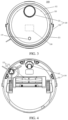
- the automatic cleaning apparatus 100 may travel on the ground according to various combinations of the movement with respect to the following three mutually perpendicular axes defined by a machine body 110: a front and rear axis X, a lateral axis Y, and a central vertical axis Z.
- a forward drive direction along the front and rear axis X is defined as "forward”
- a backward drive direction along the front and rear axis X is defined as "backward”.
- the direction of the lateral axis Y is substantially a direction that extends between the right wheel and the left wheel of the robot passing through an axis center defined by the center point of a drive wheel module 141.
- the automatic cleaning apparatus 100 can rotate around the Y-axis.
- this case is referred to as "pitch up”; and when the front part of the automatic cleaning apparatus 100 is tilted downward, and the rear part is tilted upward, this case is referred to as "pitch down".
- the robot 100 may rotate around the Z-axis. In the forward direction of the automatic cleaning apparatus 100, when the automatic cleaning apparatus 100 is tilted to the right side of the X-axis, it rotates rightward, and when the automatic cleaning apparatus 100 is tilted to the left side of the X-axis, it rotates leftward.
- the automatic cleaning apparatus 100 includes a machine body 110, a sensing system 120, a control system, a drive system 140, a cleaning system, an energy system, and a human-machine interaction system 180.
- the machine body 110 includes a front part 111 and a rear part 112, and has a substantively circular shape (circular shape in both the front and rear parts), or may have other shapes, including but not limited to an approximately D shape of a rectangular front part and a circular rear part, a rectangle of a rectangular front part and a rectangular rear part, or a square shape.
- the sensing system 120 includes a location determining device 121 disposed on the machine body 110, a collision sensor and a proximity sensor that are disposed on a buffer 122 which is on the front part 111 of the machine body 110, a cliff sensor disposed on a lower part of the machine body, and sensing devices such as a magnetometer, an accelerometer, a gyro (Gyro), an odograph (ODO) that are disposed inside the machine body, and are configured to provide various pieces of location information and motion state information of the machine to the control system 130.
- the location determining device 121 includes but is not limited to a camera and a laser direct structuring (LDS) device.
- the front part 111 of the machine body 110 may carry the buffer 122.
- the buffer 122 detects one or more events in a driving path of the automatic cleaning apparatus 100 through a sensor system such as an infrared sensor disposed thereon, and the automatic cleaning apparatus 100 may control, based on the events detected by the buffer 122 such as an obstacle or a wall, the drive wheel module 141 to cause the automatic cleaning apparatus 100 to respond to the events, such as keeping away from the obstacle.
- the control system 130 is disposed on a circuit board in the machine body 110, and includes a computing processor, such as a central processing unit and an application processor, in communication with a NAND temporary memory, such as a hard disk, a flash memory, and a random access memory.
- a computing processor such as a central processing unit and an application processor
- a NAND temporary memory such as a hard disk, a flash memory, and a random access memory.
- the application processor through a locating algorithm such as simultaneous localization and mapping (SLAM), draws an instant map of an environment in which the robot is located.
- SLAM simultaneous localization and mapping
- the control system determines a current working state, a location, and a current posture of the sweeping robot, such as crossing a doorsill, moving on a carpet, locating at a cliff, being stuck at the top or bottom, a dust box being full, and being picked up, comprehensively.
- the control system provides a specific next action policy for different cases, so that operation of the robot better meets a requirement of its owner, such that the user has a good experience.
- the drive system 140 may operate the robot 100 to travel on the ground based on a drive command with distance information and angle information (for example, x, y, and 8 components).
- the drive system 140 includes a drive wheel module 141.
- the drive wheel module 141 may control both the left wheel and the right wheel.
- the drive wheel module 141 preferably includes a left drive wheel module and a right drive wheel module.
- the left and right drive wheel modules are opposed along a lateral axis defined by the body 110.
- the robot may include one or more driven wheels 142, and the one or more driven wheels include but are not limited to universal wheels.
- the drive wheel module includes a traveling wheel, a drive motor, and a control circuit configured to control the drive motor.
- the drive wheel module may further be connected to a circuit configured to measure a drive current and an odograph.
- the drive wheel module 141 may be detachably connected to the machine body 110, so as to facilitate disassembly and maintain.
- the drive wheel may have an offset drop suspension system, which is secured to the machine body 110 in a moveable manner, for example, in a rotatable manner, and receives a spring offset that is offset downward and away from the machine body 110.
- the spring offset allows the drive wheel to keep contact and traction with the ground with a force, and a cleaning element of the automatic cleaning apparatus 100 also contacts the ground 10 with a pressure.
- the cleaning system may be a dry cleaning system and/or a wet cleaning system.
- a main cleaning function is derived from a sweeping system 151 formed by a brushroll, a dust box, a fan, an air outlet, and connection parts between the four.
- the brushroll that interferes with the ground sweeps a rubbish on the ground and rolls it to the front of a suction inlet between the brushroll and the dust box. Then, the rubbish is suctioned into the dust box by suction gas which is generated by the fan and passes through the dust box.
- the dry cleaning system may further include a side brush 152 having a rotation shaft that is angled relative to the ground to move debris into a brushroll region of the cleaning system.
- the energy system includes a rechargeable battery, such as a Ni-MH battery and a lithium battery.
- the rechargeable battery may be connected to a charging control circuit, a charging temperature detection circuit of a battery pack, and a battery under-voltage monitoring circuit.
- the charging control circuit, the charging temperature detection circuit of the battery pack, and the battery under-voltage monitoring circuit are connected to a single-chip microcomputer control circuit.
- the machine body is connected to a charging dock through a charging electrode disposed on a side or below the machine body to recharge the rechargeable battery. If dust is attached to a charging electrode which is exposed, a plastic body around the electrode may be melted and deformed due to a charge accumulation effect during charging; and even the electrode itself is deformed, and the charging cannot continue normally.
- the human-machine interaction system 180 includes a button provided on a panel on the machine body, and the buttons are configured for the user to select a function.
- the human-machine interaction system may further include a display screen and/or an indicating lamp and/or a speaker, wherein the display screen, the indicating lamp, and the speaker present a current state or function selection item of the machine to the user; and may further include a mobile phone client program.
- a mobile phone client may display a map of an environment in which the apparatus is located and a location of the apparatus to the user, so as to provide an enriched and humanized function item to the user.
- the robot automatically obtains an operation status and a location of the robot through a sensor of the robot during the robot travels.
- the robot records a current location.
- the robot automatically avoids the location, so that the robot can work continuously without being trapped at the same location for a second time, which is specifically as follows:
- an embodiment of the present disclosure provides an obstacle avoidance method for an automatic cleaning apparatus. As illustrated in FIG. 5 , the method includes the following method steps:
- Step S502 Trap feature information is obtained in real time during the robot travels, wherein the trap feature information includes a sensor parameter and/or image information.
- the trap feature information refers to a determining information that can indicate a robot to be trapped, including but not limited to a sensor parameter of a cleaning robot, image information obtained by an image collection device, radar information obtained by a radar system, and the like.
- the automatic cleaning apparatus includes a collision sensor, a proximity sensor, a cliff sensor, and sensing devices such as a magnetometer, an accelerometer, a gyro (Gyro), and an odograph (ODO) that are disposed within a machine body. These sensors provide various pieces of location information and motion status information of the machine to a control system 130 at a fixed frequency.
- the control system 130 obtains various sensor parameters of the automatic cleaning apparatus in real time during the robot travels, and further determines and analyzes a current location and operation status of the automatic cleaning apparatus.
- the automatic cleaning apparatus shoots an image in real time during the robot travels through a camera carried by the automatic cleaning apparatus, wherein image information may be complete photo information, or may be feature information which is extracted from the image and reflects the image, for example, image information obtained after a feature point is extracted.
- the feature information is an image abstract feature, such as a corner, an object boundary line, a color gradient, an optical flow gradient, and a position relationship between the features.
- the control system 130 obtains image information parameters of the automatic cleaning apparatus in real time during the robot travels, and further determines and analyzes the current location and operation status of the automatic cleaning apparatus.
- Step S504 determining whether a current location is in a trap region upon determining that the trap feature information meets a trap condition, wherein the trap region indicates a region in which the robot was trapped or is prone to be trapped.
- determining that the trap feature information meets a trap condition specifically includes: the sensor parameter exceeds a preset first threshold, wherein the sensor parameter includes any one or any combination of the following: an upward tilted angle of the robot; a difference between an angular velocity of an odograph of a primary wheel of the robot and an angular velocity of a gyroscope; and an overcurrent value of a single-wheel current or a double-wheel current of a traveling wheel of the robot.
- the sensor parameter exceeding the preset first threshold includes: when the robot is tilted upward, the upward tilted angle being greater than 2.5 degrees; and/or collecting angular velocity data of the odograph of the primary wheel of the robot and angular velocity data of the gyroscope, wherein a continuous time period in which the difference between the angular velocity of the odograph of the primary wheel of the robot and the angular velocity of the gyroscope exceeds a specified value accumulates up to more than 400 ms; and/or the overcurrent of the single-wheel current or the double-wheel current of the traveling wheel of the robot exceeding 500 mA.
- the upward tilted angle is greater than 2.5 degrees, for example, when the upward tilted angle is ranged from 2.5 to 5 degrees, an alarm is given to the control system.
- the tilt state of the automatic cleaning apparatus may be learned through a gyroscope or a tilt sensor within the apparatus, and details are not described herein.
- the angular velocity data of the odograph of the primary wheel of the automatic cleaning apparatus and the gyroscope are collected, wherein a continuous time period in which the difference between the angular velocity of the odograph of the primary wheel and the angular velocity of the gyroscope exceeds a specified value accumulates up to more than 400 ms.
- the angular velocity of the odograph of the primary wheel and the angular velocity of the gyroscope are synchronous, that is, the difference between the angular velocity of the odograph of the primary wheel and the angular velocity of the gyroscope is 0.
- a difference occurs between the angular velocity of the odograph of the primary wheel and the angular velocity of the gyroscope.
- a threshold for example, 400 ms-500 ms, it can be determined that the automatic cleaning apparatus may be trapped.
- the overcurrent of the single-wheel current or the double-wheel current of the traveling wheel of the automatic cleaning apparatus exceeds 500 mA.
- the drive wheel module includes a travelling wheel, a drive motor, and a control circuit configured to control the drive motor.
- the drive wheel module is connected a circuit configured to measure a drive current and an odograph. When the measured current value exceeds a threshold of a normal current value, such as 500 mA-800 mA, it can be determined that the automatic cleaning apparatus may be trapped.
- the step further includes: the robot labels a trap mark at a coordinate point of a trap location whenever a trap occurs during the robot travels; determining whether a current location is in a trap region specifically includes: determining whether the current location is within a specific range of a coordinate point at which a trap mark is labeled; and determining that the current location is in the trap region specifically includes: in a case that the current location is within the specific range of the coordinate point at which a trap mark is labeled, determining that the current location is in the trap region.
- the method includes: selecting a region with a area and shape around the trap location as the trap region, wherein the trap location is in the trap region.
- the foregoing range may be a circular region with a preset length as a radius and the coordinate point labeled as a trap mark as the center, or may be a quadrilateral with the coordinate point labeled as the trap mark as the center and a preset length as an edge length.
- the length of the radius and the edge length may be fixed, or may be set to different values according to different types of obstacles.
- That the automatic cleaning apparatus queries whether the current location during the robot travels is within a specified range of the coordinate point labeled with the trap mark includes that: the automatic cleaning apparatus queries, through a cloud, a remote server, or its storage apparatus, whether the current location is within a specified range of the coordinate point labeled with the trap mark.
- the trap mark is labeled in a cleaning map in advance. For example, when a trap occurs at a location in each cleaning process, such as a furniture foot, a wall corner, or a lower part of a furniture, the coordinate of the location is labeled with a trap mark. Then, when the sensor parameter is abnormal, the automatic cleaning apparatus automatically queries whether the location is within the specific range of the coordinate point labeled as the trap mark. If not, the current location is labeled with a trap mark, and if yes, obstacle avoidance is performed. For details, refer to the following procedure.
- the method further includes: saving, by the robot whenever a trap occurs during the robot travels, current scenario information collected by an image collection device; determining whether the current location is in the trap region specifically includes: comparing scenario information obtained at the current location with the saved scenario information; and determining whether the current location is in the trap region specifically includes: in a case that the similarity between the scenario information obtained at the current location and the saved scenario information exceeds a preset second threshold, determining that the current location is in the trap region.
- That the similarity between the scenario information obtained at the current location and the saved scenario information exceeds correspondingly the preset second threshold specifically includes: a coincidence rate between image information obtained at the current location and saved image information of a scenario exceeds a threshold; or the quantity of feature information of an image obtained at the current location that is consistent saved feature information of an image of a scenario exceeds a threshold.
- the location of the trap mark and a specific region around the trap mark are selected as a trap region, for example, the trap region is in a range of 10 cm.
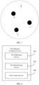
- a mapping relationship between the location of the trap mark and the trap region is constructed, that is, there are multiple trap marks a, b, and c in a trap region A.
- trap region A forms a mapping relationship with trap mark a, trap mark b, and trap mark c, as illustrated in FIG. 7 .
- a process of marking a trap location in region A is as follows: Whenever a trap occurs during the robot travels, the cleaning robot saves current scenario information collected by the image collection device. For example, when a trap occurs at locations a, b, and c, a trap mark is labeled at the locations, and image information in the direction of the image collection device is recorded, as a standard for subsequent comparison.
- the robot saves current scenario information collected by the image collection device whenever a trap occurs during the robot travels; compares the scenario information obtained at the current location with the saved scenario information; and in a case that the similarity between the scenario information obtained at the current location and the saved scenario information exceeds the preset second threshold, for example, a currently photographed image feature matches a historical image feature by more than 80%, determines that the current location is located in the trap region.
- Step S506 giving up a current traveling route and travel out of the trap region upon determining that the current location is located in the trap region.
- an extrication operation is performed, wherein the extrication operation includes but is not limited to: retreating by a distance and then turning to the left, retreating by a distance and then turning to the right, directly turning to the left, turning to the right, or the like.
- the method further includes: clearing the trap mark at the current location upon determining that the trap feature information does not meet the trap condition when the robot travels to the location of the coordinate point at which a trap mark is labeled.
- the automatic cleaning apparatus travels to the location of the trap mark, and the sensor parameter does not exceed the first threshold, it is considered that there is no obstacle at the location that may easily cause a trap, and the trap mark of the location is deleted.
- the location may previously have a chair, and subsequently does not constitute an obstacle because the chair is moved. Therefore, the trap mark is deleted.
- the automatic cleaning apparatus automatically obtains an operation status of the automatic cleaning apparatus through a sensor of the automatic cleaning apparatus during the robot travels. When it is determined, through the sensor of the automatic cleaning apparatus, that the automatic cleaning apparatus is trapped, a current location is recorded. When subsequently running to the location again, because the location has been marked previously, the automatic cleaning apparatus automatically bypasses the location, so that the automatic cleaning apparatus can continuously work without being trapped at the same location twice, thereby improving automatic cleaning continuity of the automatic cleaning apparatus, working efficiency, and user experience.
- this embodiment of the present disclosure provides an obstacle avoidance method for an automatic cleaning apparatus. As illustrated in FIG. 6 , the method includes the following steps:
- Step S602 Trap feature information is obtained in real time during the robot travels, wherein the trap feature information includes image information.
- the trap feature information indicates any information that can cause a robot to be trapped, including but not limited to any sensor parameter of a cleaning robot, image information obtained by an image collection device, radar information obtained by a radar system, and the like.
- the automatic cleaning apparatus picks up an image in real time during the robot travels through a camera carried by the automatic cleaning apparatus, wherein the image information may be complete photo information, or may be feature information which is extracted from the image to reflect the image, for example, image information obtained after a feature point is extracted.
- the feature information is an image abstract feature, such as a corner, an object boundary line, a color gradient, an optical flow gradient, and a position relationship between the features.
- Step S604 determining whether a current location is located in a trap region upon determining that the trap feature information meets a trap condition, wherein the trap region indicates to a region in which the robot was trapped or is prone to be trapped.
- the robot saves, whenever a trap occurs during the robot travels, current scenario information collected by an image collection device; and determining whether the trap feature information meets a trap condition specifically includes: comparing scenario information obtained at a current location with the saved scenario information; and it is determined that the trap feature information meets the trap condition in a case of similarity between the two pieces of scenario information exceeding a preset third threshold.
- the method further includes: saving, by the robot whenever a trap occurs during the robot travels, current scenario information collected by an image collection device; determining whether a current location is located in the trap region specifically includes: comparing scenario information obtained at a current location with the saved scenario information; and determining whether the current location is located in the trap region specifically includes: determining that the current location is in the trap region in a case of the similarity between the two pieces of scenario information exceeding a preset second threshold.
- the similarity between the two pieces of scenario information correspondingly exceeding the preset second threshold or the preset third threshold specifically includes: a coincidence rate between image information obtained at the current location and saved image information of a scenario exceeding a threshold; or a quantity of feature information of an image obtained at the current location that is consistent with saved feature information of an image of a scenario exceeds a threshold.
- the third threshold is required to be less than the second threshold.
- the location of the trap mark and a specific region around the trap mark are selected as a trap region.
- a mapping relationship between the location of the trap mark and the trap region is established, that is, there are multiple trap marks, namely trap mark a, trap mark b, and trap mark c, in trap region A.
- trap mark a trap mark a
- trap mark b trap mark c
- trap region A forms there is a mapping relationship between the trap region A and trap mark a, trap mark b, and trap mark c, as illustrated in FIG. 7 .
- a process of labeling a trap mark at a trap location in region A is as follows: whenever a trap occurs during the robot travels, the cleaning robot saves current scenario information collected by the image collection device. For example, when a trap occurs at locations a, b, or c, a trap mark is label at the location, and image information in a direction in which the image collection device is oriented is recorded, as a standard for subsequent comparison.
- the robot saves current scenario information collected through the image collection device whenever a trap occurs during the robot travels; compares the scenario information obtained at the current location with the saved scenario information; and determines that the trap feature information meets the trap condition in a case that the similarity between the two pieces of scenario information exceeds the preset third threshold, for example, a currently photographed image feature matches a historical image feature by more than 60%.
- the robot saves current scenario information collected by the image collection device whenever a trap occurs during the robot travels; compares the scenario information obtained at the current location with the saved scenario information; and determines that the current location is located in the trap region in a case that the similarity between the two pieces of scenario information exceeds the preset second threshold, for example, a currently photographed image feature matches a historical image feature by more than 80%.
- the image information that is obtained by the camera in a current traveling route is enough to determine that there is an obstacle, for example, when a wall or a cabinet is photographed in the front, historical image information of the location is obtained, and the current image information is compared with the historical image information.
- the similarity between the current image information and the historical image information is relatively high, for example, at least 80%, it indicates that there is likely an obstacle that causes a trap, and the obstacle is directly avoided. Otherwise, when the similarity between the two pieces of image information is relatively low, for example, 30%, it is considered that this location is relatively safe, and the autonomous cleaning apparatus may continue to travel according to an original route.
- the method After labeling a trap mark at a coordinate point of a trap location, the method includes: selecting a region with an area and a shape around the trap location as the trap region, wherein the trap location is located in the trap region.
- the foregoing range may be a circular region with a preset length as a radius and the coordinate point labeled as the trap mark as a center, or may be a quadrilateral with the coordinate point labeled as the trap mark as a center and with a preset length as an edge length.
- the length of the radius and the edge length may be fixed, or may be set to different values according to various types of obstacles.
- Step S606 upon determining that the current location is located in the trap region, a current traveling route is given up and the autonomous cleaning apparatus travels out of the trap region.
- the method further includes: deleting corresponding saved scenario information in a case that no trap feature information meeting the trap condition is detected within a period of time when traveling to the trap region.
- the method further includes: clearing the trap mark from the current location upon determining that the trap feature information does not meet the trap condition when the robot travels to the location of the coordinate point at which a trap mark is labeled.
- trap mark a located in region A it is required to determine whether the current image feature information is consistent with the historically stored image information, so as to confirm the trap mark a.
- the currently photographed image feature matches the historical image feature by at least 80%, it is considered that the trap mark at the current location is valid according to the current image information.
- the trap mark that has been confirmed for two times may be taken as a permanent mark.
- the automatic cleaning apparatus travels to the location again, the automatic cleaning apparatus directly avoid the obstacle without determining whether the location is a trap location.
- the currently photographed image feature matches the historical image feature by 70%, it is considered that it can be determined that there is no obstacle according to the current image feature information, and the obstacle mark is cleared. For example, there was a chair at the location previously, and now the chair is removed and there is no obstacle, and thus the obstacle mark is cleared.
- the automatic cleaning apparatus automatically obtains an operation status of the automatic cleaning apparatus through a sensor of the automatic cleaning apparatus during the robot travels.
- a current location is recorded.
- the automatic cleaning apparatus automatically avoid the location, so that the automatic cleaning apparatus can continuously work without being trapped at the same location for a second time, thereby enhancing the continuity of automatic cleaning operation of the automatic cleaning apparatus, and improving working efficiency and user experience.
- an embodiment of the present disclosure provides an obstacle avoidance device applicable to an automatic cleaning apparatus, configured to implement the obstacle avoidance method described in the foregoing embodiment.
- the same technical feature produces the same technical effect, and details are not elaborated herein.
- an embodiment of the present disclosure provides an obstacle avoidance device applicable to an automatic cleaning apparatus, including:
- determining that the trap feature information meets a trap condition specifically includes: the sensor parameter exceeding a preset first threshold, wherein the sensor parameter includes any one or any combination of the following: an upward tilted angle of the robot; a difference between an angular velocity of an odograph of a primary wheel of the robot and an angular velocity of a gyroscope; and an overcurrent value of a single-wheel current or a double-wheel current of a traveling wheel of the robot.
- the sensor parameter exceeding the preset first threshold includes: the upward tilted angle being greater than 2.5 degrees when the robot is tilted upward; and/or collecting angular velocity data of the odograph of the primary wheel of the robot and angular velocity data of the gyroscope, wherein a continuous time period in which a difference between the angular velocity of the odograph of the primary wheel and the angular velocity of the gyroscope exceeds a specified value for at least accumulates up to more than 400 ms; and/or the overcurrent of the single-wheel current or the double-wheel current of the traveling wheel of the robot exceeding 500 mA.
- the robot labels a trap mark at a coordinate point of a trap location whenever a trap occurs during the robot travels; determining whether the current location is located in a trap region specifically includes: determining whether the current location is located within a specific range of a coordinate point at which a trap mark is labeled; and determining that the current location is located in the trap region specifically includes: in a case that the current location located is within the specific range of the coordinate point at which a trap mark is labeled, determining that the current location is located in the trap region.
- the following is included: selecting a region with an area and a shape around the trap location as the trap region, wherein the trap location is located in the trap region.
- a first control unit 806 is configured to give up a current traveling route and travel out of the trap region upon determining that the current location is in the trap region.
- the following is further included: clearing the trap mark at the current location upon determining the trap feature information does not meet the trap condition when the robot travels to the location of the coordinate point at which a trap mark is labeled.
- the automatic cleaning apparatus automatically obtains an operation status of the automatic cleaning apparatus during the robot travels through a sensor of the automatic cleaning apparatus.
- a current location is recorded.
- the automatic cleaning apparatus automatically avoids the location, so that the automatic cleaning apparatus can continuously work without being trapped at the same location for a second time, thereby enhancing continuity of automatic cleaning operation of the automatic cleaning apparatus, and improving working efficiency and user experience.
- an embodiment of the present disclosure provides an obstacle avoidance device applicable to an automatic cleaning apparatus, including:
- the robot saves, whenever a trap occurs during the robot travels, current scenario information collected by an image collection device; and determining whether the trap feature information meets a trap condition specifically includes: comparing scenario information obtained at the current location with the saved scenario information; and determining that the trap feature information meets the trap condition when the similarity between the two pieces of scenario information exceeds a preset third threshold.
- the robot saves, whenever a trap occurs during the robot travels, current scenario information collected by an image collection device; determining whether the current location is located in the trap region specifically includes: comparing scenario information obtained at the current location with the saved scenario information; and determining that the current location is located in the trap region specifically includes: determining that the current location is located in the trap region when the similarity between the two pieces of scenario information exceeds a preset second threshold.
- That the similarity between the two pieces of scenario information correspondingly exceeds the preset second threshold or third threshold specifically includes: a coincidence rate between image information obtained at the current location and saved image information of a scenario exceeding a threshold; or a quantity of feature information of an image obtained at the current location that is consistent with saved feature information of an image of a scenario exceeding a threshold.
- the third threshold is required to be less than the second threshold.
- the foregoing range may be a circular region with a preset length as a radius and with the coordinate point labeled as a trap mark as the center, or may be a quadrilateral with the coordinate point labeled as a trap mark as the center and with a preset length as an edge length.
- the length of the radius and the edge length may be fixed, or may be set to different values according to various types of obstacles.
- a second control unit 906 is configured to: give up a current traveling route and travel out of the trap region upon determining that the current location is located in the trap region.
- the following is further included: deleting corresponding saved scenario information in a case that no trap feature information meeting the trap condition is detected within a period of time when traveling to the trap region.
- the following is further included: clearing the trap mark at the current location upon determining that no trap feature information meets the trap condition when the robot travels to a location of the coordinate point at which a trap mark is labeled.
- the automatic cleaning apparatus automatically obtains an operation status of the automatic cleaning apparatus during the robot travels through a sensor of the automatic cleaning apparatus. Upon determining, according to the image collection device, that the automatic cleaning apparatus is trapped, a current location is recorded. When subsequently traveling to the location again, because the location has been labeled previously, the automatic cleaning apparatus automatically avoids the location, so that the automatic cleaning apparatus can continuously work without being trapped at the same location for a second time, thereby enhancing continuity of automatic cleaning operation of the automatic cleaning apparatus, and improving working efficiency and user experience.
- an embodiment of the present disclosure provides an obstacle avoidance method applicable to an automatic cleaning apparatus. As illustrated in FIG. 10 , the method includes the following method steps:
- Step S1002 trap feature information is obtained in real time during the robot travels, wherein the trap feature information includes image information.
- the trap feature information refers to any determining information that can cause a robot to be trapped, including but not limited to any sensor parameter of a cleaning robot, image information obtained by an image collection device, radar information obtained by a radar system, and the like.
- the automatic cleaning apparatus shoots an image in real time during traveling by a camera carried by the automatic cleaning apparatus, wherein image information may be complete photo information, or may be feature information that is extracted from the image to reflect the image, for example, image information obtained after extracting a feature point.
- the feature information is an image abstract feature, such as a corner, an object boundary line, a color gradient, an optical flow gradient, and a position relationship between the features.
- Step S1004 monitoring a sensor parameter in real time upon determining that the trap feature information meets a trap condition.
- Determining that the trap feature information meets a trap condition specifically includes: the image information includes a preset obstacle or scenario that is prone to cause a trap.
- the robot saves current scenario information collected by the image collection device whenever a trap occurs during the robot travels; compares the scenario information obtained at the current location with the saved scenario information; and determines that the current image information includes a scenario that is prone to cause a trap when the similarity between the two pieces of scenario information exceeds the preset threshold, for example, a currently photographed image feature matches a historical image feature by more than 60%,.
- the robot saves an obstacle collected by the image collection device whenever a trap occurs during the robot travels; compares the obstacle obtained at the current location with the saved obstacle; and determines that the current image information includes an obstacle that may cause a trap when similarity between the two obstacles exceeds a preset threshold, for example, a currently photographed obstacle feature matches a historical obstacle feature by more than 80%.
- the sensor parameter includes any one or any combination of the following: an upward tilted angle of the robot; a difference between an angular velocity of an odograph of a primary wheel of the robot and an angular velocity of a gyroscope; and an overcurrent value of a single-wheel current or a double-wheel current of a traveling wheel of the robot.
- Step S1006 When it is detected that the sensor parameter exceeds a preset value, change a current traveling route.
- the sensor parameter exceeding the preset value includes: when the robot is tilted upward, the upward tilted angle being greater than 2.5 degrees; and/or collecting angular velocity data of the odograph of the primary wheel of the robot and angular velocity data of the gyroscope, wherein a continuous time period in which the difference between the angular velocity of the odograph of the primary wheel of the robot and the angular velocity of the gyroscope exceeds a specified value accumulates up to more than 400 ms; and/or the overcurrent of the single-wheel current or the double-wheel current of the traveling wheel of the robot exceeding 500 mA.
- the upward tilted angle is greater than 2.5 degrees, for example, when the upward tilted angle is 2.5 to 5 degrees, an alarm is sent to the control system.
- the tilt state of the automatic cleaning apparatus may be acquired by a gyroscope or a tilt sensor disposed inside the apparatus, and details are not described herein.
- the angular velocity data of the odograph of the primary wheel of the automatic cleaning apparatus and the gyroscope are collected, wherein a continuous time period in which the difference between the angular velocity of the odograph of the primary wheel and the angular velocity of the gyroscope exceeds a specified value accumulates up to more than 400 ms.
- the angular velocity of the odograph of the primary wheel and the angular velocity of the gyroscope are synchronous, that is, the difference between the angular velocity of the odograph of the primary wheel and the angular velocity of the gyroscope is 0.
- the overcurrent of the single-wheel current or the double-wheel current of the traveling wheel of the automatic cleaning apparatus exceeds 500 mA.
- the drive wheel module includes a traveling wheel, a drive motor, and a control circuit configured to the drive motor.
- the drive wheel module connects a circuit configured to measure a drive current and an odograph. When the measured current value exceeds a normal current value by a threshold, such as 500 mA-800 mA, it may be determined that the automatic cleaning apparatus may be trapped.
- the automatic cleaning apparatus Upon determining that the sensor parameter exceeds the preset value, the automatic cleaning apparatus gives up the current traveling route, and travels out of the trap region.
- the traveling manner includes but is not limited to: retreating by a distance and then turning to the left, retreating by a distance and then turning to the right, directly turning to the left or the right, or the like.
- the automatic cleaning apparatus constructs a trap scenario model or an obstacle model by an image sensor during the robot travels.
- a potential trap is determined by the image sensor, and combined with the sensor parameter of the automatic cleaning apparatus obtained by another sensor, it is further determined whether a current location is a trap location.
- the traveling route is changed, so that the automatic cleaning apparatus can continuously work without being trapped at the same location for a second time, thereby enhancing automatic cleaning continuity of the automatic cleaning apparatus, and improving working efficiency and user experience.
- an embodiment of the present disclosure provides an obstacle avoidance device applicable to an automatic cleaning apparatus.
- the apparatus includes:
- Determining that the trap feature information meets a trap condition specifically includes: the image information includes a preset obstacle or scenario that is prone to cause a trap.
- the sensor parameter includes any one or any combination of the following: an upward tilted angle of the robot; a difference between an angular velocity of an odograph of a primary wheel of the robot and an angular velocity of a gyroscope; and an overcurrent value of a single-wheel current or a double-wheel current of a traveling wheel of the robot.
- An operation unit 1106 is configured to change a current traveling route when the sensor parameter exceeding a preset value detected.
- the sensor parameter exceeding the preset value includes: when the robot is tilted upward, the upward tilted angle being greater than 2.5 degrees; and/or collecting angular velocity data of the odograph of the primary wheel of the robot and angular velocity data of the gyroscope, wherein a continuous time period in which the difference between the angular velocity of the odograph of the primary wheel and the angular velocity of the gyroscope exceeds a specified value accumulates up to more than 400 ms; and/or the overcurrent of the single-wheel current or the double-wheel current of the traveling wheel of the robot exceeding 500 mA.
- the automatic cleaning apparatus constructs a trap scenario model or an obstacle model through an image sensor during the robot travels.
- a potential trap is determined through the image sensor, and combined with the sensor parameter of the automatic cleaning apparatus obtained by other sensor, it is further determined whether a current location is a trap location.
- the traveling route is given up, so that the automatic cleaning apparatus can continuously work without being trapped at the same location for a second time, thereby enhancing continuity of automatic cleaning operation of the automatic cleaning apparatus, improving working efficiency and user experience.
- An embodiment of the present disclosure provides a non-transitory computer readable storage medium, on which a computer program instruction is stored, and the computer program instruction implements operations of any one of the foregoing methods when being invoked and executed by a processor.
- An embodiment of the present disclosure provides a robot, including a processor and a memory, wherein the memory stores a computer program instruction that can be executed by the processor, and the processor implements operations of the method according to any one of the foregoing embodiments when executing the computer program instruction.
- the robot may include a processing device (such as a central processing unit, a graphics processing unit, or the like) 1201 that may perform various appropriate actions and processing according to a program stored in a read-only memory (ROM) 1202 or a program loaded from a storage apparatus 1208 into a random access memory (RAM) 1203.
- ROM read-only memory
- RAM random access memory
- various programs and data required for operation of an electronic robot 1200 are further stored.
- the processing device 1201, the ROM 1202, and the RAM 1203 are connected to each other through a bus 1204.
- An input/output (I/O) interface 1205 is also connected to the bus 1204.
- the following devices may be connected to the I/O interface 1205: an input device 1206 including, for example, a touchscreen, a touchpad, a keyboard, a mouse, a camera, a microphone, an accelerometer, and a gyroscope; an output device 1207 including, for example, a liquid crystal display (LCD), a loudspeaker and a vibrator; a storage device 1208 including, for example, a hard disk; and a communications device 1209.
- the communications device 1209 may enable the electronic robot to communicate wirelessly or wiredly with another robot to exchange data.
- FIG. 12 illustrates an electronic robot with various devices, it should be understood that it is not required to implement or provide all illustrated devices. Alternatively, more or fewer devices may be implemented or provided.
- an embodiment of the present disclosure includes a robot software program product that includes a computer program carried on a readable medium, and the computer program includes program code configured to perform operations of the method illustrated in the flowchart.
- the computer program may be downloaded from a network through the communications device 1209 and installed, or may be installed from the storage apparatus 1208, or may be installed from the ROM 1202.
- the processing device 1201 When the computer program is executed by the processing device 1201, the foregoing functions defined in the method according to the embodiments of the present disclosure are performed.
- the foregoing computer readable medium in the present disclosure may be a computer readable signal medium, a computer readable storage medium, or any combination thereof.
- the computer readable storage medium may be, for example, an electrical, magnetic, optical, electromagnetic, infrared, or semiconductor system, apparatus, or device, or any combination thereof. More specific examples of the computer readable storage medium may include but are not limited to: an electrical connection having one or more wires, a portable computer magnetic disk, a hard disk, a random access memory (RAM), a read-only memory (ROM), an erasable programmable read-only memory (EPROM or flash memory), an optical fiber, a portable compact disk read-only memory (CD-ROM), an optical storage device, a magnetic storage device, or any suitable combination thereof.
- the computer readable storage medium may be any tangible medium that includes or stores a program, and the program may be used by an instruction execution system, device, or apparatus, or a combination thereof.
- the computer readable signal medium may include a data signal propagated in a baseband or as a part of a carrier, which carries computer readable program code. Such a propagated data signal may be in multiple forms, including but not limited to an electromagnetic signal, an optical signal, or any suitable combination thereof.
- the computer readable signal medium may further be any computer readable medium other than the computer readable storage medium, and the computer readable signal medium may send, propagate, or transmit a program that is used by an instruction execution system, device, or apparatus, or a combination thereof.
- the program code included in the computer readable medium may be transmitted through any suitable medium, including but not limited to: a wire, an optical cable, a radio frequency (RF), or any suitable combination thereof.
- RF radio frequency
- the computer readable medium may be included in the foregoing robot, or may exist separately and not be assembled into the robot.
- Computer program code for performing the operations of the present disclosure may be written in one or more programming languages or a combination thereof, such as object-oriented programming languages Java, Smalltalk, C++, and conventional procedural programming languages such as "C" or similar program design languages.
- the program code may be executed on a user computer, completely or partially, or as an independent package, or on a user computer partially and on a remote computer partially, or on a remote computer or server completely.
- the remote computer may be connected to a user computer through any type of network, including a local area network (LAN) or a wide area network (WAN), or may be connected to an external computer (for example, through the Internet by an Internet service provider).
- LAN local area network
- WAN wide area network
- Internet service provider for example, AT&T, MCI, Sprint, EarthLink, MSN, GTE, etc.
- each block in the flowcharts or block diagrams may represent a module, program segment, or part of code that includes one or more executable instructions for implementing a specified logical function.
- functions marked in the block may also be performed in different order than those marked in the accompanying drawings. For example, two blocks represented in succession may actually be executed in actually parallel, and they may sometimes be executed in a reverse order, depending on the functions involved.
- each block in the block diagram and/or flowchart and a combination of blocks in the block diagram and/or flowchart may be implemented by a dedicated hardware-based system that performs a specified function or operation, or may be implemented by a combination of a dedicated hardware and a computer instruction.
- the apparatus embodiment described above is merely illustrative.
- the units described as separate parts may or may not be physically separate, and parts displayed as units may or may not be physical units, can be located in one location, or can be distributed on a plurality of network units. Some or all of the modules can be selected according to actual requirements to implement the solutions of the embodiments.
- One of ordinary skill in the art can understand and implement the embodiments of the present application without creative efforts.
Landscapes
- Engineering & Computer Science (AREA)
- Physics & Mathematics (AREA)
- Remote Sensing (AREA)
- Radar, Positioning & Navigation (AREA)
- Aviation & Aerospace Engineering (AREA)
- General Physics & Mathematics (AREA)
- Automation & Control Theory (AREA)
- Electromagnetism (AREA)
- Computer Vision & Pattern Recognition (AREA)
- Optics & Photonics (AREA)
- Multimedia (AREA)
- Acoustics & Sound (AREA)
- Control Of Position, Course, Altitude, Or Attitude Of Moving Bodies (AREA)
- Electric Vacuum Cleaner (AREA)
Applications Claiming Priority (2)
| Application Number | Priority Date | Filing Date | Title |
|---|---|---|---|
| CN202010292306.4A CN111427357A (zh) | 2020-04-14 | 2020-04-14 | 一种机器人避障方法、装置和存储介质 |
| PCT/CN2021/070297 WO2021208530A1 (zh) | 2020-04-14 | 2021-01-05 | 一种机器人避障方法、装置和存储介质 |
Publications (3)
| Publication Number | Publication Date |
|---|---|
| EP4137905A1 true EP4137905A1 (de) | 2023-02-22 |
| EP4137905A4 EP4137905A4 (de) | 2024-04-17 |
| EP4137905B1 EP4137905B1 (de) | 2026-04-29 |
Family
ID=71557952
Family Applications (1)
| Application Number | Title | Priority Date | Filing Date |
|---|---|---|---|
| EP21788887.4A Active EP4137905B1 (de) | 2020-04-14 | 2021-01-05 | Verfahren, vorrichtung und speichermedium zur vermeidung von roboterhindernissen |
Country Status (4)
| Country | Link |
|---|---|
| US (1) | US20230200613A1 (de) |
| EP (1) | EP4137905B1 (de) |
| CN (2) | CN111427357A (de) |
| WO (1) | WO2021208530A1 (de) |
Cited By (1)
| Publication number | Priority date | Publication date | Assignee | Title |
|---|---|---|---|---|
| EP4137905A4 (de) * | 2020-04-14 | 2024-04-17 | Beijing Roborock Innovation Technology Co., Ltd. | Verfahren, vorrichtung und speichermedium zur vermeidung von roboterhindernissen |
Families Citing this family (19)
| Publication number | Priority date | Publication date | Assignee | Title |
|---|---|---|---|---|
| CN114153197B (zh) * | 2020-08-17 | 2023-08-18 | 速感科技(北京)有限公司 | 自主移动设备的脱困方法及装置 |
| CN118898739A (zh) * | 2020-11-06 | 2024-11-05 | 北京石头创新科技有限公司 | 一种识别障碍物的方法、装置、介质和电子设备 |
| US11612295B2 (en) | 2021-01-04 | 2023-03-28 | Beijing Roborock Technology Co., Ltd. | Autonomous cleaning device |
| CN112890690B (zh) * | 2021-01-28 | 2022-08-12 | 深圳拓邦股份有限公司 | 机器人清扫控制方法、装置及扫地机器人 |
| CN113679290B (zh) * | 2021-02-10 | 2022-11-08 | 北京石头创新科技有限公司 | 自动清洁设备控制方法及装置、介质及电子设备 |
| WO2022171158A1 (zh) * | 2021-02-10 | 2022-08-18 | 北京石头创新科技有限公司 | 自动清洁设备清洁方法及装置、介质及电子设备 |
| CN115644738A (zh) | 2021-02-10 | 2023-01-31 | 北京石头创新科技有限公司 | 清洁机器人脱困方法及装置、介质及电子设备 |
| CN114625117B (zh) * | 2021-05-06 | 2025-08-22 | 北京石头世纪科技股份有限公司 | 一种智能移动设备及其控制方法、电子设备、存储介质 |
| CN113907650A (zh) * | 2021-10-21 | 2022-01-11 | 珠海一微半导体股份有限公司 | 一种双清洁机器人协同清理污渍的方法及系统 |
| CN116076949B (zh) * | 2021-11-05 | 2025-08-05 | 追觅创新科技(苏州)有限公司 | 清洁设备的控制方法、及清洁设备 |
| CN114217608B (zh) * | 2021-11-24 | 2024-04-19 | 深圳市优必选科技股份有限公司 | 障碍物位置确定方法、装置、电子设备及存储介质 |
| CN116551663B (zh) * | 2022-01-27 | 2025-10-28 | 追觅创新科技(苏州)有限公司 | 机器人控制方法、装置、机器人及存储介质 |
| CN114557640B (zh) * | 2022-02-21 | 2023-08-01 | 广州宝乐软件科技有限公司 | 清洁机器人的数据处理方法、装置及清洁机器人 |
| CN117315038A (zh) * | 2022-06-21 | 2023-12-29 | 松灵机器人(深圳)有限公司 | 异常区域标定方法及相关装置 |
| JP1771034S (ja) * | 2022-12-30 | 2024-05-21 | 掃除ロボット | |
| TWD231050S (zh) * | 2023-02-28 | 2024-05-01 | 大陸商北京石頭世紀科技股份有限公司 (中國大陸) | 清潔機器人 |
| CN116269048A (zh) * | 2023-03-15 | 2023-06-23 | 北京石头创新科技有限公司 | 自移清洁设备及其控制方法、装置和存储介质 |
| CN116360442A (zh) * | 2023-03-29 | 2023-06-30 | 北京石头创新科技有限公司 | 自行走设备防跌落的控制方法及装置 |
| CN120000104B (zh) * | 2025-04-18 | 2025-09-09 | 追觅科技(苏州)有限公司 | 清洁机器人的清洁方法 |
Family Cites Families (28)
| Publication number | Priority date | Publication date | Assignee | Title |
|---|---|---|---|---|
| JP4333611B2 (ja) * | 2005-03-16 | 2009-09-16 | パナソニック電工株式会社 | 移動体用の障害物検出装置 |
| JP5086942B2 (ja) * | 2008-09-02 | 2012-11-28 | トヨタ自動車株式会社 | 経路探索装置、経路探索方法、及び経路探索プログラム |
| CN105899112B (zh) * | 2014-01-10 | 2018-07-06 | 艾罗伯特公司 | 自主移动机器人 |
| CN106205223A (zh) * | 2016-09-21 | 2016-12-07 | 江西天祥通用航空股份有限公司 | 一种针对障碍物的预警方法及系统 |
| CN106774312B (zh) * | 2016-12-05 | 2020-04-28 | 遨博(北京)智能科技有限公司 | 一种为移动机器人确定移动轨迹的方法和装置 |
| CN107049155B (zh) * | 2017-04-25 | 2020-03-03 | 北京小米移动软件有限公司 | 扫地机器人的控制方法和装置 |
| CN107092260B (zh) * | 2017-06-09 | 2020-11-20 | 北京小米移动软件有限公司 | 移动机器人及该移动机器人跨越障碍物的方法 |
| KR102448287B1 (ko) * | 2017-08-08 | 2022-09-28 | 삼성전자주식회사 | 전자 장치 및 그 동작 방법 |
| CN107443430B (zh) * | 2017-09-12 | 2019-11-05 | 珠海市一微半导体有限公司 | 智能机器人碰撞障碍物的检测方法及建图方法 |
| CN107943025B (zh) * | 2017-11-09 | 2020-12-15 | 珠海市一微半导体有限公司 | 机器人脱困的处理方法 |
| CN108873880A (zh) * | 2017-12-11 | 2018-11-23 | 北京石头世纪科技有限公司 | 智能移动设备及其路径规划方法、计算机可读存储介质 |
| CN110340882A (zh) * | 2018-04-08 | 2019-10-18 | 苏州宝时得电动工具有限公司 | 机器人避障方法、装置、计算机设备及存储介质 |
| CN108958263A (zh) * | 2018-08-03 | 2018-12-07 | 江苏木盟智能科技有限公司 | 一种机器人避障方法及机器人 |
| CN109375618A (zh) * | 2018-09-27 | 2019-02-22 | 深圳乐动机器人有限公司 | 清洁机器人的导航避障方法及终端设备 |
| CN109528089B (zh) * | 2018-11-19 | 2021-03-23 | 珠海市一微半导体有限公司 | 一种被困清洁机器人的继续行走方法、装置及芯片 |
| CN109394086A (zh) * | 2018-11-19 | 2019-03-01 | 珠海市微半导体有限公司 | 一种基于被困的清洁机器人的继续行走方法、装置及芯片 |
| CN109645892B (zh) * | 2018-12-12 | 2021-05-28 | 深圳乐动机器人有限公司 | 一种障碍物的识别方法及清洁机器人 |
| CN109947109B (zh) * | 2019-04-02 | 2022-06-21 | 北京石头创新科技有限公司 | 机器人工作区域地图构建方法、装置、机器人和介质 |
| US11865717B2 (en) * | 2019-04-08 | 2024-01-09 | Lg Electronics Inc. | Method of controlling movement of cart robot in response to change in travel surface using artificial intelligence and cart robot implementing the same |
| CN110051292B (zh) * | 2019-05-29 | 2021-11-02 | 尚科宁家(中国)科技有限公司 | 一种扫地机器人控制方法 |
| CN110338708B (zh) * | 2019-06-21 | 2021-04-09 | 华为技术有限公司 | 一种扫地机器人的清扫控制方法及设备 |
| CN110244743B (zh) * | 2019-07-03 | 2022-02-01 | 浙江大学 | 一种融合多传感器信息的移动机器人自主脱困方法 |
| KR102298582B1 (ko) * | 2019-07-12 | 2021-09-08 | 엘지전자 주식회사 | 센서 데이터를 이용하여 청소 동선을 결정하는 인공 지능 로봇 및 그 방법 |
| CN110448241B (zh) * | 2019-07-18 | 2021-05-18 | 华南师范大学 | 机器人被困检测及脱困方法 |
| EP4006681B1 (de) * | 2019-07-23 | 2024-10-16 | Honda Motor Co., Ltd. | Autonome arbeitsmaschine, verfahren zur steuerung einer autonomen arbeitsmaschine |
| CN110554696B (zh) * | 2019-08-14 | 2023-01-17 | 深圳银星智能集团股份有限公司 | 机器人系统、机器人及基于激光雷达的机器人导航方法 |
| CN110974088B (zh) * | 2019-11-29 | 2021-09-24 | 深圳市杉川机器人有限公司 | 扫地机器人控制方法、扫地机器人及存储介质 |
| CN111427357A (zh) * | 2020-04-14 | 2020-07-17 | 北京石头世纪科技股份有限公司 | 一种机器人避障方法、装置和存储介质 |
-
2020
- 2020-04-14 CN CN202010292306.4A patent/CN111427357A/zh active Pending
- 2020-04-14 CN CN202511695499.7A patent/CN121209520A/zh active Pending
-
2021
- 2021-01-05 EP EP21788887.4A patent/EP4137905B1/de active Active
- 2021-01-05 US US17/906,711 patent/US20230200613A1/en active Pending
- 2021-01-05 WO PCT/CN2021/070297 patent/WO2021208530A1/zh not_active Ceased
Cited By (1)
| Publication number | Priority date | Publication date | Assignee | Title |
|---|---|---|---|---|
| EP4137905A4 (de) * | 2020-04-14 | 2024-04-17 | Beijing Roborock Innovation Technology Co., Ltd. | Verfahren, vorrichtung und speichermedium zur vermeidung von roboterhindernissen |
Also Published As
| Publication number | Publication date |
|---|---|
| CN111427357A (zh) | 2020-07-17 |
| WO2021208530A1 (zh) | 2021-10-21 |
| EP4137905A4 (de) | 2024-04-17 |
| US20230200613A1 (en) | 2023-06-29 |
| CN121209520A (zh) | 2025-12-26 |
| EP4137905B1 (de) | 2026-04-29 |
Similar Documents
| Publication | Publication Date | Title |
|---|---|---|
| EP4137905B1 (de) | Verfahren, vorrichtung und speichermedium zur vermeidung von roboterhindernissen | |
| US12390069B2 (en) | Obstacle avoidance method and device for self-walking robot, robot, and storage medium | |
| US12572148B2 (en) | Method for detecting obstacle, self-moving robot, and non-transitory computer readable storage medium | |
| CN114468898B (zh) | 机器人语音控制方法、装置、机器人和介质 | |
| US12608006B2 (en) | Ranging method and apparatus, robot, and storage medium | |
| CN110136704B (zh) | 机器人语音控制方法、装置、机器人和介质 | |
| CN114675636A (zh) | 自主移动机器人及其寻桩方法、控制装置和自主移动系统 | |
| CN114504276A (zh) | 自主移动机器人及其寻桩方法和控制装置 | |
| CN114595354A (zh) | 机器人的建图方法、装置、机器人和存储介质 | |
| EP4446843A1 (de) | Steuerungsverfahren für eine selbstgehende vorrichtung, selbstgehende vorrichtung und speichermedium | |
| CN114010102B (zh) | 一种清洁机器人 | |
| TW202305534A (zh) | 機器人避障方法及其相關裝置、機器人、儲存介質及電子設備 | |
| CN114601399A (zh) | 清洁设备的控制方法、装置、清洁设备和存储介质 | |
| CN113625700B (zh) | 自行走机器人控制方法、装置、自行走机器人和存储介质 | |
| CN114610013A (zh) | 自行走机器人的遇障处理方法、装置、机器人和存储介质 | |
| CN112022026A (zh) | 自行走机器人及障碍物检测方法 | |
| CN213216762U (zh) | 自行走机器人 | |
| AU2024227177A1 (en) | Method and apparatus for detecting obstacle, self-moving robot, and storage medium. | |
| TW202437992A (zh) | 自移動設備及其控制方法、存儲媒介、計算機設備 | |
| CN114601373A (zh) | 清洁机器人的控制方法、装置、清洁机器人和存储介质 |
Legal Events
| Date | Code | Title | Description |
|---|---|---|---|
| STAA | Information on the status of an ep patent application or granted ep patent |
Free format text: STATUS: THE INTERNATIONAL PUBLICATION HAS BEEN MADE |
|
| PUAI | Public reference made under article 153(3) epc to a published international application that has entered the european phase |
Free format text: ORIGINAL CODE: 0009012 |
|
| STAA | Information on the status of an ep patent application or granted ep patent |
Free format text: STATUS: REQUEST FOR EXAMINATION WAS MADE |
|
| 17P | Request for examination filed |
Effective date: 20221104 |
|
| AK | Designated contracting states |
Kind code of ref document: A1 Designated state(s): AL AT BE BG CH CY CZ DE DK EE ES FI FR GB GR HR HU IE IS IT LI LT LU LV MC MK MT NL NO PL PT RO RS SE SI SK SM TR |
|
| DAV | Request for validation of the european patent (deleted) | ||
| DAX | Request for extension of the european patent (deleted) | ||
| REG | Reference to a national code |
Ref legal event code: R079 Ref country code: DE Ref legal event code: R079 Ref document number: 602021053220 Country of ref document: DE Free format text: PREVIOUS MAIN CLASS: G05D0001020000 Ipc: G05D0001000000 |
|
| A4 | Supplementary search report drawn up and despatched |
Effective date: 20240315 |
|
| RIC1 | Information provided on ipc code assigned before grant |
Ipc: A47L 11/24 20060101ALI20240311BHEP Ipc: A47L 11/40 20060101ALI20240311BHEP Ipc: G05D 1/00 20060101AFI20240311BHEP |
|
| STAA | Information on the status of an ep patent application or granted ep patent |
Free format text: STATUS: EXAMINATION IS IN PROGRESS |
|
| 17Q | First examination report despatched |
Effective date: 20250411 |
|
| GRAP | Despatch of communication of intention to grant a patent |
Free format text: ORIGINAL CODE: EPIDOSNIGR1 |
|
| STAA | Information on the status of an ep patent application or granted ep patent |
Free format text: STATUS: GRANT OF PATENT IS INTENDED |
|
| INTG | Intention to grant announced |
Effective date: 20251127 |
|
| GRAS | Grant fee paid |
Free format text: ORIGINAL CODE: EPIDOSNIGR3 |
|
| GRAA | (expected) grant |
Free format text: ORIGINAL CODE: 0009210 |
|
| STAA | Information on the status of an ep patent application or granted ep patent |
Free format text: STATUS: THE PATENT HAS BEEN GRANTED |
|
| AK | Designated contracting states |
Kind code of ref document: B1 Designated state(s): AL AT BE BG CH CY CZ DE DK EE ES FI FR GB GR HR HU IE IS IT LI LT LU LV MC MK MT NL NO PL PT RO RS SE SI SK SM TR |
|
| REG | Reference to a national code |
Ref country code: CH Ref legal event code: F10 Free format text: ST27 STATUS EVENT CODE: U-0-0-F10-F00 (AS PROVIDED BY THE NATIONAL OFFICE) Effective date: 20260429 |