EP4137937B1 - Partage croisé de bibliothèque de projets d'automatisation industrielle - Google Patents
Partage croisé de bibliothèque de projets d'automatisation industrielle Download PDFInfo
- Publication number
- EP4137937B1 EP4137937B1 EP22189177.3A EP22189177A EP4137937B1 EP 4137937 B1 EP4137937 B1 EP 4137937B1 EP 22189177 A EP22189177 A EP 22189177A EP 4137937 B1 EP4137937 B1 EP 4137937B1
- Authority
- EP
- European Patent Office
- Prior art keywords
- project
- automation
- industrial
- library
- ide
- Prior art date
- Legal status (The legal status is an assumption and is not a legal conclusion. Google has not performed a legal analysis and makes no representation as to the accuracy of the status listed.)
- Active
Links
Images









Classifications
-
- G—PHYSICS
- G06—COMPUTING OR CALCULATING; COUNTING
- G06F—ELECTRIC DIGITAL DATA PROCESSING
- G06F8/00—Arrangements for software engineering
- G06F8/70—Software maintenance or management
- G06F8/71—Version control; Configuration management
-
- G—PHYSICS
- G05—CONTROLLING; REGULATING
- G05B—CONTROL OR REGULATING SYSTEMS IN GENERAL; FUNCTIONAL ELEMENTS OF SUCH SYSTEMS; MONITORING OR TESTING ARRANGEMENTS FOR SUCH SYSTEMS OR ELEMENTS
- G05B19/00—Program-control systems
- G05B19/02—Program-control systems electric
- G05B19/418—Total factory control, i.e. centrally controlling a plurality of machines, e.g. direct or distributed numerical control [DNC], flexible manufacturing systems [FMS], integrated manufacturing systems [IMS] or computer integrated manufacturing [CIM]
- G05B19/41835—Total factory control, i.e. centrally controlling a plurality of machines, e.g. direct or distributed numerical control [DNC], flexible manufacturing systems [FMS], integrated manufacturing systems [IMS] or computer integrated manufacturing [CIM] characterised by program execution
-
- G—PHYSICS
- G05—CONTROLLING; REGULATING
- G05B—CONTROL OR REGULATING SYSTEMS IN GENERAL; FUNCTIONAL ELEMENTS OF SUCH SYSTEMS; MONITORING OR TESTING ARRANGEMENTS FOR SUCH SYSTEMS OR ELEMENTS
- G05B19/00—Program-control systems
- G05B19/02—Program-control systems electric
- G05B19/04—Program control other than numerical control, i.e. in sequence controllers or logic controllers
- G05B19/042—Program control other than numerical control, i.e. in sequence controllers or logic controllers using digital processors
- G05B19/0426—Programming the control sequence
-
- G—PHYSICS
- G05—CONTROLLING; REGULATING
- G05B—CONTROL OR REGULATING SYSTEMS IN GENERAL; FUNCTIONAL ELEMENTS OF SUCH SYSTEMS; MONITORING OR TESTING ARRANGEMENTS FOR SUCH SYSTEMS OR ELEMENTS
- G05B19/00—Program-control systems
- G05B19/02—Program-control systems electric
- G05B19/418—Total factory control, i.e. centrally controlling a plurality of machines, e.g. direct or distributed numerical control [DNC], flexible manufacturing systems [FMS], integrated manufacturing systems [IMS] or computer integrated manufacturing [CIM]
- G05B19/41845—Total factory control, i.e. centrally controlling a plurality of machines, e.g. direct or distributed numerical control [DNC], flexible manufacturing systems [FMS], integrated manufacturing systems [IMS] or computer integrated manufacturing [CIM] characterised by system universality, reconfigurability, modularity
-
- G—PHYSICS
- G05—CONTROLLING; REGULATING
- G05B—CONTROL OR REGULATING SYSTEMS IN GENERAL; FUNCTIONAL ELEMENTS OF SUCH SYSTEMS; MONITORING OR TESTING ARRANGEMENTS FOR SUCH SYSTEMS OR ELEMENTS
- G05B19/00—Program-control systems
- G05B19/02—Program-control systems electric
- G05B19/418—Total factory control, i.e. centrally controlling a plurality of machines, e.g. direct or distributed numerical control [DNC], flexible manufacturing systems [FMS], integrated manufacturing systems [IMS] or computer integrated manufacturing [CIM]
- G05B19/4185—Total factory control, i.e. centrally controlling a plurality of machines, e.g. direct or distributed numerical control [DNC], flexible manufacturing systems [FMS], integrated manufacturing systems [IMS] or computer integrated manufacturing [CIM] characterised by the network communication
-
- G—PHYSICS
- G06—COMPUTING OR CALCULATING; COUNTING
- G06F—ELECTRIC DIGITAL DATA PROCESSING
- G06F8/00—Arrangements for software engineering
- G06F8/30—Creation or generation of source code
- G06F8/34—Graphical or visual programming
-
- G—PHYSICS
- G05—CONTROLLING; REGULATING
- G05B—CONTROL OR REGULATING SYSTEMS IN GENERAL; FUNCTIONAL ELEMENTS OF SUCH SYSTEMS; MONITORING OR TESTING ARRANGEMENTS FOR SUCH SYSTEMS OR ELEMENTS
- G05B2219/00—Program-control systems
- G05B2219/20—Pc systems
- G05B2219/23—Pc programming
- G05B2219/23258—GUI graphical user interface, icon, function bloc editor, labview
-
- G—PHYSICS
- G05—CONTROLLING; REGULATING
- G05B—CONTROL OR REGULATING SYSTEMS IN GENERAL; FUNCTIONAL ELEMENTS OF SUCH SYSTEMS; MONITORING OR TESTING ARRANGEMENTS FOR SUCH SYSTEMS OR ELEMENTS
- G05B2219/00—Program-control systems
- G05B2219/20—Pc systems
- G05B2219/23—Pc programming
- G05B2219/23261—Use control template library
-
- G—PHYSICS
- G05—CONTROLLING; REGULATING
- G05B—CONTROL OR REGULATING SYSTEMS IN GENERAL; FUNCTIONAL ELEMENTS OF SUCH SYSTEMS; MONITORING OR TESTING ARRANGEMENTS FOR SUCH SYSTEMS OR ELEMENTS
- G05B2219/00—Program-control systems
- G05B2219/20—Pc systems
- G05B2219/23—Pc programming
- G05B2219/23424—Select construction element from function library
Definitions
- US 2020/285462 A1 relates to a computer-implemented method that includes uploading, by a first instance of an integrated development environment (IDE), a first source-code change to a change log of a version control system.
- a second instance of the IDE is used to upload a second source-code change to the change log of the version control system.
- a determination is made that the second source-code change conflicts with the first source-code change.
- generating a notification of the second source-code change is generated in the first instance of the IDE.
- YooHoo awareness system that will help developers in loose organizations to keep apprised of any code changes that are specifically relevant to the source code for which they are responsible.
- YooHoo will perform lightweight static analysis on a developer's code to identify a list of external dependencies that the code relies upon. Using the list of external dependencies, YooHoo connects with the change repositories for these systems and retrieves information for these entities at the file-level. YooHoo will determine if a change modifies any parts of the file that correspond to entities the developer is dependent upon and will then the nature of the change.
- YooHoo will provide a variety of notification mechanisms to give change notifications a visual prominence appropriate to their severity.
- US 2021/096553 A1 relates to an industrial integrated development environment (IDE) which supports collaborative tools that allow multiple designers and programmers to remotely submit design input to the same automation system project in parallel while maintaining project consistency. These collaborative features can include generating notifications to remote designers when a portion of the system project is modified.
- IDE industrial integrated development environment
- a system for developing industrial applications comprising a memory that stores executable components and shared libraries of automation objects representing respective industrial assets, the automation objects having respective programmatic attributes associated with the industrial assets; a user interface component configured to render integrated development environment (IDE) interfaces and to receive, via interaction with the IDE interfaces, design input that defines aspects of an industrial automation project; and a project generation component configured to generate system project data based on the design input, the system project data comprising instances of one or more of the automation objects stored in one or more of the shared libraries to which the system project is mapped, wherein the system project data defines a system project comprising at least one of an executable industrial control program, an industrial visualization application, or industrial device configuration data, and the project generation component is configured to, in response to receipt of an edit to an automation object in one of the shared libraries: determine whether an instance of the automation object is included in the system project data, and cause the user interface component to render, via one or more of the IDE interfaces, a notification indicating that the automation object has been edited in
- one or more embodiments provide a method for developing industrial applications, comprising rendering, by a system comprising a processor, integrated development environment (IDE) interfaces on a client device; receiving, by the system via interaction with the IDE interfaces, design input that defines aspects of an industrial control and monitoring project; generating, by the system, system project data based on the design input, the system project data comprising instances of one or more of the automation objects stored in one or more shared libraries of automation objects, wherein the generating comprises generating at least one of an executable industrial control program, an industrial visualization application, or industrial device configuration data; and in response to receipt of an edit to an automation object in a library of the shared libraries: determining, by the system, whether an instance of the automation object is included in the system project data, and rendering, by the system via one or more of the IDE interfaces, a notification indicating that the automation object has been edited in the library.
- IDE integrated development environment
- a non-transitory computer-readable medium having stored thereon instructions that, in response to execution, cause a system to perform operations, the operations comprising rendering integrated development environment (IDE) interfaces on a client device; receiving, from the client device via interaction with the IDE interfaces, design input that defines control design aspects of an industrial automation project; generating system project data based on the design input, wherein the generating comprises generating at least one of an executable industrial control program, an industrial visualization application, or industrial device configuration data, and the system project data comprises instances of automation objects selected from one or more shared libraries of automation objects, the automation objects representing respective industrial assets and having respective programmatic attributes relating to the industrial assets; and in response to receipt of an edit to an automation object in a library of the shared libraries: determining whether an instance of the automation object is included in the system project data, and rendering, via one or more of the IDE interfaces, a notification indicating that the automation object has been edited in the library.
- IDE integrated development environment
- the terms "component,” “system,” “platform,” “layer,” “controller,” “terminal,” “station,” “node,” “interface” are intended to refer to a computer-related entity or an entity related to, or that is part of, an operational apparatus with one or more specific functionalities, wherein such entities can be either hardware, a combination of hardware and software, software, or software in execution.
- a component can be, but is not limited to being, a process running on a processor, a processor, a hard disk drive, multiple storage drives (of optical or magnetic storage medium) including affixed (e.g., screwed or bolted) or removable affixed solid-state storage drives; an object; an executable; a thread of execution; a computer-executable program, and/or a computer.
- affixed e.g., screwed or bolted
- the components may communicate via local and/or remote processes such as in accordance with a signal having one or more data packets (e.g., data from one component interacting with another component in a local system, distributed system, and/or across a network such as the Internet with other systems via the signal).
- a component can be an apparatus with specific functionality provided by mechanical parts operated by electric or electronic circuitry which is operated by a software or a firmware application executed by a processor, wherein the processor can be internal or external to the apparatus and executes at least a part of the software or firmware application.
- a component can be an apparatus that provides specific functionality through electronic components without mechanical parts, the electronic components can include a processor therein to execute software or firmware that provides at least in part the functionality of the electronic components.
- interface(s) can include input/output (I/O) components as well as associated processor, application, or Application Programming Interface (API) components. While the foregoing examples are directed to aspects of a component, the exemplified aspects or features also apply to a system, platform, interface, layer, controller, terminal, and the like.
- I/O input/output
- API Application Programming Interface
- the terms "to infer” and “inference” refer generally to the process of reasoning about or inferring states of the system, environment, and/or user from a set of observations as captured via events and/or data. Inference can be employed to identify a specific context or action, or can generate a probability distribution over states, for example. The inference can be probabilistic-that is, the computation of a probability distribution over states of interest based on a consideration of data and events. Inference can also refer to techniques employed for composing higher-level events from a set of events and/or data. Such inference results in the construction of new events or actions from a set of observed events and/or stored event data, whether or not the events are correlated in close temporal proximity, and whether the events and data come from one or several event and data sources.
- the term "or” is intended to mean an inclusive “or” rather than an exclusive “or.” That is, unless specified otherwise, or clear from the context, the phrase “X employs A or B” is intended to mean any of the natural inclusive permutations. That is, the phrase “X employs A or B” is satisfied by any of the following instances: X employs A; X employs B; or X employs both A and B.
- the articles “a” and “an” as used in this application and the appended claims should generally be construed to mean “one or more” unless specified otherwise or clear from the context to be directed to a singular form.
- a “set” in the subject disclosure includes one or more elements or entities.
- a set of controllers includes one or more controllers; a set of data resources includes one or more data resources; etc.
- group refers to a collection of one or more entities; e.g., a group of nodes refers to one or more nodes.
- FIG. 1 is a block diagram of an example industrial control environment 100.
- a number of industrial controllers 118 are deployed throughout an industrial plant environment to monitor and control respective industrial systems or processes relating to product manufacture, machining, motion control, batch processing, material handling, or other such industrial functions.
- Industrial controllers 118 typically execute respective control programs to facilitate monitoring and control of industrial devices 120 making up the controlled industrial assets or systems (e.g., industrial machines).
- One or more industrial controllers 118 may also comprise a soft controller executed on a personal computer or other hardware platform, or on a cloud platform. Some hybrid devices may also combine controller functionality with other functions (e.g., visualization).
- the control programs executed by industrial controllers 118 can comprise substantially any type of code capable of processing input signals read from the industrial devices 120 and controlling output signals generated by the industrial controllers 118, including but not limited to ladder logic, sequential function charts, function block diagrams, or structured text.
- Industrial devices 120 may include both input devices that provide data relating to the controlled industrial systems to the industrial controllers 118, and output devices that respond to control signals generated by the industrial controllers 118 to control aspects of the industrial systems.
- Example input devices can include telemetry devices (e.g., temperature sensors, flow meters, level sensors, pressure sensors, etc.), manual operator control devices (e.g., push buttons, selector switches, etc.), safety monitoring devices (e.g., safety mats, safety pull cords, light curtains, etc.), and other such devices.
- Output devices may include motor drives, pneumatic actuators, signaling devices, robot control inputs, valves, pumps, and the like.
- Industrial controllers 118 may communicatively interface with industrial devices 120 over hardwired or networked connections.
- industrial controllers 118 can be equipped with native hardwired inputs and outputs that communicate with the industrial devices 120 to effect control of the devices.
- the native controller I/O can include digital I/O that transmits and receives discrete voltage signals to and from the field devices, or analog 1/O that transmits and receives analog voltage or current signals to and from the devices.
- the controller I/O can communicate with a controller's processor over a backplane such that the digital and analog signals can be read into and controlled by the control programs.
- Industrial controllers 118 can also communicate with industrial devices 120 over a network using, for example, a communication module or an integrated networking port.
- Exemplary networks can include the Internet, intranets, Ethernet, DeviceNet, ControlNet, Data Highway and Data Highway Plus (DH/DH+), Remote I/O, Fieldbus, Modbus, Profibus, wireless networks, serial protocols, and the like.
- the industrial controllers 118 can also store persisted data values that can be referenced by their associated control programs and used for control decisions, including but not limited to measured or calculated values representing operational states of a controlled machine or process (e.g., tank levels, positions, alarms, etc.) or captured time series data that is collected during operation of the automation system (e.g., status information for multiple points in time, diagnostic occurrences, etc.).
- some intelligent devices including but not limited to motor drives, instruments, or condition monitoring modules - may store data values that are used for control and/or to visualize states of operation. Such devices may also capture time-series data or events on a log for later retrieval and viewing.
- HMIs human-machine interfaces
- Industrial automation systems often include one or more human-machine interfaces (HMIs) 114 that allow plant personnel to view telemetry and status data associated with the automation systems, and to control some aspects of system operation.
- HMIs 114 may communicate with one or more of the industrial controllers 118 over a plant network 116, and exchange data with the industrial controllers to facilitate visualization of information relating to the controlled industrial processes on one or more pre-developed operator interface screens.
- HMIs 114 can also be configured to allow operators to submit data to specified data tags or memory addresses of the industrial controllers 118, thereby providing a means for operators to issue commands to the controlled systems (e.g., cycle start commands, device actuation commands, etc.), to modify setpoint values, etc.
- commands e.g., cycle start commands, device actuation commands, etc.
- HMIs 114 can generate one or more display screens through which the operator interacts with the industrial controllers 118, and thereby with the controlled processes and/or systems.
- Example display screens can visualize present states of industrial systems or their associated devices using graphical representations of the processes that display metered or calculated values, employ color or position animations based on state, render alarm notifications, or employ other such techniques for presenting relevant data to the operator. Data presented in this manner is read from industrial controllers 118 by HMIs 114 and presented on one or more of the display screens according to display formats chosen by the HMI developer.
- HMIs may comprise fixed location or mobile devices with either user-installed or pre-installed operating systems, and either user-installed or pre-installed graphical application software.
- Some industrial environments may also include other systems or devices relating to specific aspects of the controlled industrial systems. These may include, for example, a data historian 110 that aggregates and stores production information collected from the industrial controllers 118 or other data sources, device documentation stores containing electronic documentation for the various industrial devices making up the controlled industrial systems, inventory tracking systems, work order management systems, repositories for machine or process drawings and documentation, vendor product documentation storage, vendor knowledgebases, internal knowledgebases, work scheduling applications, or other such systems, some or all of which may reside on an office network 108 of the industrial environment.
- a data historian 110 that aggregates and stores production information collected from the industrial controllers 118 or other data sources
- device documentation stores containing electronic documentation for the various industrial devices making up the controlled industrial systems
- inventory tracking systems work order management systems
- repositories for machine or process drawings and documentation vendor product documentation storage
- vendor knowledgebases vendor knowledgebases
- internal knowledgebases internal knowledgebases
- work scheduling applications or other such systems, some or all of which may reside on an office network 108 of the industrial environment
- Higher-level systems 126 may carry out functions that are less directly related to control of the industrial automation systems on the plant floor, and instead are directed to long term planning, high-level supervisory control, analytics, reporting, or other such high-level functions. These systems 126 may reside on the office network 108 at an external location relative to the plant facility, or on a cloud platform with access to the office and/or plant networks. Higher-level systems 126 may include, but are not limited to, cloud storage and analysis systems, big data analysis systems, manufacturing execution systems, data lakes, reporting systems, etc. In some scenarios, applications running at these higher levels of the enterprise may be configured to analyze control system operational data, and the results of this analysis may be fed back to an operator at the control system or directly to a controller 118 or device 120 in the control system.
- control programming development application such as a ladder logic editor (e.g., executing on a client device 124).
- a designer can write control programming (e.g., ladder logic, structured text, function block diagrams, etc.) for carrying out a desired industrial sequence or process and download the resulting program files to the controller 118.
- developers design visualization screens and associated navigation structures for HMIs 114 using an HMI development platform (e.g., executing on client device 122) and download the resulting visualization files to the HMI 114.
- Some industrial devices 120 - such as motor drives, telemetry devices, safety input devices, etc. - may also require configuration using separate device configuration tools (e.g., executing on client device 128) that are specific to the device being configured.
- device configuration tools may be used to set device parameters or operating modes (e.g., high/low limits, output signal formats, scale factors, energy consumption modes, etc.).
- a motion control system may require an industrial controller to be programmed and a control loop to be tuned using a control logic programming platform, a motor drive to be configured using another configuration platform, and an associated HMI to be programmed using a visualization development platform.
- Related peripheral systems such as vision systems, safety systems, etc. - may also require configuration using separate programming or development applications.
- one or more embodiments described herein provide an integrated development environment (IDE) for designing, programming, and configuring multiple aspects of an industrial automation system using a common design environment and data model.
- IDE integrated development environment
- Embodiments of the industrial IDE can be used to configure and manage automation system devices in a common way, facilitating integrated, multi-discipline programming of control, visualization, and other aspects of the control system.
- the industrial IDE supports features that span the full automation lifecycle, including design (e.g., device selection and sizing, controller programming, visualization development, device configuration, testing, etc.); installation, configuration and commissioning; operation, improvement, and administration; and troubleshooting, expanding, and upgrading.
- design e.g., device selection and sizing, controller programming, visualization development, device configuration, testing, etc.
- installation, configuration and commissioning e.g., installation, configuration and commissioning
- operation, improvement, and administration e.g., troubleshooting, expanding, and upgrading.
- Embodiments of the industrial IDE can include a library of modular code and visualizations that are specific to industry verticals and common industrial applications within those verticals. These code and visualization modules can simplify development and shorten the development cycle, while also supporting consistency and reuse across an industrial enterprise.
- embodiments of the IDE system can be built on an object-based model rather than, or in addition to, a tag-based architecture.
- the IDE system can support the use of automation objects that serve as building blocks for this object-based development structure.
- automation objects that serve as building blocks for this object-based development structure.
- embodiments of the IDE system can use automation object inheritance features to propagate changes made to an automation object definition to all instances of the automation object used throughout a control project.
- the IDE system can also support creation of multiple shared libraries of automation objects or other project components. This allows users to create one or more custom libraries of project components, which can be built from existing project components from other libraries or populated with new custom components. Projects can then reference one or more of these shared libraries so that components in those libraries can be selectively imported into those projects. Notification features can inform users whose projects reference a shared library when an object or component within that library has been updated by one of the users. Each user can then opt to either synchronize the object or component modification to their own project, or decline synchronization of the modification to their project.
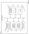
- FIG. 2 is a block diagram of an example integrated development environment (IDE) system 202 according to one or more embodiments of this disclosure.
- IDE integrated development environment
- IDE system 202 can include a user interface component 204 including an IDE editor 224, a project generation component 206, a project deployment component 208, a project testing component 210, a collaboration management component 212, one or more processors 218, and memory 220.
- a user interface component 204 including an IDE editor 224, a project generation component 206, a project deployment component 208, a project testing component 210, a collaboration management component 212, one or more processors 218, and memory 220.
- one or more of the user interface component 204, project generation component 206, project deployment component 208, project testing component 210, collaboration management component 212, the one or more processors 218, and memory 220 can be electrically and/or communicatively coupled to one another to perform one or more of the functions of the IDE system 202.
- components 204, 206, 208, 210, and 212 can comprise software instructions stored on memory 220 and executed by processor(s) 218.
- IDE system 202 may also interact with other hardware and/or software components not depicted in FIG. 2 .
- processor(s) 218 may interact with one or more external user interface devices, such as a keyboard, a mouse, a display monitor, a touchscreen, or other such interface devices.
- User interface component 204 can be configured to receive user input and to render output to the user in any suitable format (e.g., visual, audio, tactile, etc.).
- user interface component 204 can be configured to communicatively interface with an IDE client that executes on a client device (e.g., a laptop computer, tablet computer, smart phone, etc.) that is communicatively connected to the IDE system 202 (e.g., via a hardwired or wireless connection). The user interface component 204 can then receive user input data and render output data via the IDE client.
- user interface component 314 can be configured to generate and serve suitable interface screens to a client device (e.g., program development screens), and exchange data via these interface screens.
- Input data that can be received via various embodiments of user interface component 204 can include, but is not limited to, programming code, industrial design specifications or goals, engineering drawings, AR/VR input, DSL definitions, video or image data, project testing scripts, or other such input.
- Output data rendered by various embodiments of user interface component 204 can include program code, programming feedback (e.g., error and highlighting, coding suggestions, etc.), programming and visualization development screens, project testing results, etc.
- Project generation component 206 can be configured to create a system project comprising one or more project files based on design input received via the user interface component 204, as well as industrial knowledge, predefined code modules and visualizations, and automation objects 222 maintained by the IDE system 202.
- Project deployment component 208 can be configured to commission the system project created by the project generation component 206 to appropriate industrial devices (e.g., controllers, HMI terminals, motor drives, AR/VR systems, etc.) for execution. To this end, project deployment component 208 can identify the appropriate target devices to which respective portions of the system project should be sent for execution, translate these respective portions to formats understandable by the target devices, and deploy the translated project components to their corresponding devices.
- Project testing component 210 can be configured to execute testing scripts associated with automation objects 222 or other elements of the system project to validate proper execution of various aspects of the project.
- Collaboration management component 212 can be configured to track instances of a system project that have been downloaded to local client devices so that these local versions of the project can be updated as needed in response to modifications submitted to the cloud-based IDE system.
- the one or more processors 218 can perform one or more of the functions described herein with reference to the systems and/or methods disclosed.
- Memory 220 can be a computer-readable storage medium storing computer-executable instructions and/or information for performing the functions described herein with reference to the systems and/or methods disclosed.
- FIG. 3 is a diagram illustrating a generalized architecture of the industrial IDE system 202 according to one or more embodiments.
- Industrial IDE system 202 can implement a common set of services and workflows spanning not only design, but also commissioning, operation, and maintenance. In terms of design, the IDE system 202 can support not only industrial controller programming and HMI development, but also sizing and selection of system components, device/system configuration, AR/VR visualizations, and other features.
- the IDE system 202 can also include tools that simplify and automate commissioning of the resulting project and assist with subsequent administration of the deployed system during runtime.
- Embodiments of the IDE system 202 that are implemented on a cloud platform also facilitate collaborative project development whereby multiple developers 304 contribute design and programming input to a common automation system project 302. Collaborative tools supported by the IDE system can manage design contributions from the multiple contributors and perform version control of the aggregate system project 302 to ensure project consistency.
- IDE system 202 Based on design and programming input from one or more developers 304, IDE system 202 generates a system project 302 comprising one or more project files.
- the system project 302 encodes one or more of control programming; HMI, AR, and/or VR visualizations; device or sub-system configuration data (e.g., drive parameters, vision system configurations, telemetry device parameters, safety zone definitions, etc.); or other such aspects of an industrial automation system being designed.
- IDE system 202 can identify the appropriate target devices 306 on which respective aspects of the system project 302 should be executed (e.g., industrial controllers, HMI terminals, variable frequency drives, safety devices, etc.), translate the system project 302 to executable files that can be executed on the respective target devices, and deploy the executable files to their corresponding target devices 306 for execution, thereby commissioning the system project 302 to the plant floor for implementation of the automation project.
- target devices 306 e.g., industrial controllers, HMI terminals, variable frequency drives, safety devices, etc.
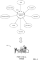
- FIG. 4 is a diagram illustrating several example automation object properties that can be leveraged by the IDE system 202 in connection with building, deploying, and executing a system project 302. Automation objects 222 can be created and augmented during design, integrated into larger data models, and consumed during runtime. These automation objects 222 provide a common data structure across the IDE system 202 and can be stored in an object library (e.g., part of memory 220) for reuse.
- object library e.g., part of memory 220
- the object library can store predefined automation objects 222 representing various classifications of real-world industrial assets 402, including but not limited to pumps, tanks, values, motors, motor drives (e.g., variable frequency drives), industrial robots, actuators (e.g., pneumatic or hydraulic actuators), or other such assets.
- Automation objects 222 can represent elements at substantially any level of an industrial enterprise, including individual devices, machines made up of many industrial devices and components (some of which may be associated with their own automation objects 222), and entire production lines or process control systems.
- An automation object 222 for a given type of industrial asset can encode such aspects as 2D or 3D visualizations, alarms, control coding (e.g., logic or other type of control programming), analytics, startup procedures, testing protocols and scripts, validation reports, simulations, schematics, security protocols, and other such properties associated with the industrial asset 402 represented by the object 222.
- Automation objects 222 can also be geotagged with location information identifying the location of the associated asset.
- the automation object 222 corresponding to a given real-world asset 402 can also record status or operational history data for the asset.
- automation objects 222 serve as programmatic representations of their corresponding industrial assets 402, and can be incorporated into a system project 302 as elements of control code, a 2D or 3D visualization, a knowledgebase or maintenance guidance system for the industrial assets, or other such aspects. Also, as will be discussed in more detail below, automation objects 222 can support inheritance, such that changes to any of the attributes of an automation object 222 discussed above are automatically propagated to instances of the automation object used throughout a system project 302.
- FIG. 5 is a diagram illustrating example data flows associated with creation of a system project 302 for an automation system being designed using IDE system 202 according to one or more embodiments.
- a client device 504 e.g., a laptop computer, tablet computer, desktop computer, mobile device, wearable AR/VR appliance, etc.
- IDE client application 514 can access the IDE system's project development tools and leverage these tools to create a comprehensive system project 302 for an automation system being developed.
- developers can submit design input 512 to the IDE system 202 in various supported formats, including industry-specific control programming (e.g., control logic, structured text, sequential function charts, etc.) and HMI screen configuration input.
- industry-specific control programming e.g., control logic, structured text, sequential function charts, etc.
- HMI screen configuration input e.g., HMI screen configuration input.
- user interface component 204 Based on this design input 512 and information stored in an industry knowledgebase (predefined code modules 508 and visualizations 510, guardrail templates 506, physics-based rules 516, etc.), user interface component 204 renders design feedback 518 designed to assist the developer in connection with developing a system project 302 for configuration, control, and visualization of an industrial automation system.
- an industry knowledgebase predefined code modules 508 and visualizations 510, guardrail templates 506, physics-based rules 516, etc.
- IDE system 202 can be configured to receive digital engineering drawings (e.g., computer-aided design (CAD) files) as design input 512.
- project generation component 206 can generate portions of the system project 302 - e.g., by automatically generating control and/or visualization code - based on analysis of existing design drawings.
- Drawings that can be submitted as design input 512 can include, but are not limited to, P&ID drawings, mechanical drawings, flow diagrams, or other such documents.
- a P&ID drawing can be imported into the IDE system 202, and project generation component 206 can identify elements (e.g., tanks, pumps, etc.) and relationships therebetween conveyed by the drawings.
- Project generation component 206 can associate or map elements identified in the drawings with appropriate automation objects 222 corresponding to these elements (e.g., tanks, pumps, etc.) and add these automation objects 222 to the system project 302.
- the device-specific and asset-specific automation objects 222 include suitable code and visualizations to be associated with the elements identified in the drawings.
- the IDE system 202 can examine one or more different types of drawings (mechanical, electrical, piping, etc.) to determine relationships between devices, machines, and/or assets (including identifying common elements across different drawings) and intelligently associate these elements with appropriate automation objects 222, code modules 508, and/or visualizations 510.
- the IDE system 202 can leverage physics-based rules 516 as well as pre-defined code modules 508 and visualizations 510 as necessary in connection with generating code or project data for system project 302.
- the IDE system 202 can also determine whether pre-defined visualization content is available for any of the objects discovered in the drawings and generate appropriate HMI screens or AR/VR content for the discovered objects based on these pre-defined visualizations. To this end, the IDE system 202 can store industry-specific, asset-specific, and/or application-specific visualizations 510 that can be accessed by the project generation component 206 as needed. These visualizations 510 can be classified according to industry or industrial vertical (e.g., automotive, food and drug, oil and gas, pharmaceutical, etc.), type of industrial asset (e.g., a type of machine or industrial device), a type of industrial application (e.g., batch processing, flow control, web tension control, sheet metal stamping, water treatment, etc.), or other such categories.
- industry or industrial vertical e.g., automotive, food and drug, oil and gas, pharmaceutical, etc.
- type of industrial asset e.g., a type of machine or industrial device
- a type of industrial application e.g., batch processing, flow control,
- Predefined visualizations 510 can comprise visualizations in a variety of formats, including but not limited to HMI screens or windows, mashups that aggregate data from multiple pre-specified sources, AR overlays, VR objects representing 3D virtualizations of the associated industrial asset, or other such visualization formats.
- IDE system 202 can select a suitable visualization for a given object based on a predefined association between the object type and the visualization content.
- markings applied to an engineering drawing by a user can be understood by some embodiments of the project generation component 206 to convey a specific design intention or parameter.
- a marking in red pen can be understood to indicate a safety zone
- two circles connected by a dashed line can be interpreted as a gearing relationship
- a bold line may indicate a camming relationship.
- the project generation component 206 can learn permissives and interlocks (e.g., valves and their associated states) that serve as necessary preconditions for starting a machine based on analysis of the user's CAD drawings.
- Project generation component 206 can generate any suitable code (ladder logic, function blocks, etc.), device configurations, and visualizations based on analysis of these drawings and markings for incorporation into system project 302.
- user interface component 204 can include design tools for developing engineering drawings within the IDE platform itself, and the project generation component 206 can generate this code as a background process as the user is creating the drawings for a new project.
- project generation component 206 can also translate state machine drawings to a corresponding programming sequence, yielding at least skeletal code that can be enhanced by the developer with additional programming details as needed.
- IDE system 202 can support goal-based automated programming.
- the user interface component 204 can allow the user to specify production goals for an automation system being designed (e.g., specifying that a bottling plant being designed must be capable of producing at least 5000 bottles per second during normal operation) and any other relevant design constraints applied to the design project (e.g., budget limitations, available floor space, available control cabinet space, etc.). Based on this information, the project generation component 206 will generate portions of the system project 302 to satisfy the specified design goals and constraints.
- Portions of the system project 302 that can be generated in this manner can include, but are not limited to, device and equipment selections (e.g., definitions of how many pumps, controllers, stations, conveyors, drives, or other assets will be needed to satisfy the specified goal), associated device configurations (e.g., tuning parameters, network settings, drive parameters, etc.), control coding, or HMI screens suitable for visualizing the automation system being designed.
- device and equipment selections e.g., definitions of how many pumps, controllers, stations, conveyors, drives, or other assets will be needed to satisfy the specified goal
- associated device configurations e.g., tuning parameters, network settings, drive parameters, etc.
- control coding e.g., control coding, or HMI screens suitable for visualizing the automation system being designed.
- Some embodiments of the project generation component 206 can also generate at least some of the project code for system project 302 based on knowledge of parts that have been ordered for the project being developed. This can involve accessing the customer's account information maintained by an equipment vendor to identify devices that have been purchased for the project. Based on this information the project generation component 206 can add appropriate automation objects 222 and associated code modules 508 corresponding to the purchased assets, thereby providing a starting point for project development.
- Some embodiments of project generation component 206 can also monitor customer-specific design approaches for commonly programmed functions (e.g., pumping applications, batch processes, palletizing operations, etc.) and generate recommendations for design modules (e.g., code modules 508, visualizations 510, etc.) that the user may wish to incorporate into a current design project based on an inference of the designer's goals and learned approaches to achieving the goal.
- design modules e.g., code modules 508, visualizations 510, etc.
- some embodiments of project generation component 206 can be configured to monitor design input 512 over time and, based on this monitoring, learn correlations between certain design actions (e.g., addition of certain code modules or snippets to design projects, selection of certain visualizations, etc.) and types of industrial assets, industrial sequences, or industrial processes being designed.
- Project generation component 206 can record these learned correlations and generate recommendations during subsequent project development sessions based on these correlations. For example, if project generation component 206 determines, based on analysis of design input 512, that a designer is currently developing a control project involving a type of industrial equipment that has been programmed and/or visualized in the past in a repeated, predictable manner, the project generation component 206 can instruct user interface component 204 to render recommended development steps or code modules 508 the designer may wish to incorporate into the system project 302 based on how this equipment was configured and/or programmed in the past.
- IDE system 202 can also store and implement guardrail templates 506 that define design guardrails intended to ensure the project's compliance with internal or external design standards. Based on design parameters defined by one or more selected guardrail templates 506, user interface component 204 can provide, as a subset of design feedback 518, dynamic recommendations or other types of feedback designed to guide the developer in a manner that ensures compliance of the system project 302 with internal or external requirements or standards (e.g., certifications such as TUV certification, in-house design standards, industry-specific or vertical-specific design standards, etc.).
- certifications such as TUV certification, in-house design standards, industry-specific or vertical-specific design standards, etc.
- This feedback 518 can take the form of text-based recommendations (e.g., recommendations to rewrite an indicated portion of control code to comply with a defined programming standard), syntax highlighting, error highlighting, auto-completion of code snippets, or other such formats.
- IDE system 202 can customize design feedback 518 - including programming recommendations, recommendations of predefined code modules 508 or visualizations 510, error and syntax highlighting, etc. - in accordance with the type of industrial system being developed and any applicable in-house design standards.
- Guardrail templates 506 can also be designed to maintain compliance with global best practices applicable to control programming or other aspects of project development. For example, user interface component 204 may generate and render an alert if a developer's control programing is deemed to be too complex as defined by criteria specified by one or more guardrail templates 506. Since different verticals (e.g., automotive, pharmaceutical, oil and gas, food and drug, marine, etc.) must adhere to different standards and certifications, the IDE system 202 can maintain a library of guardrail templates 506 for different internal and external standards and certifications, including customized user-specific guardrail templates 506. These guardrail templates 506 can be classified according to industrial vertical, type of industrial application, plant facility (in the case of custom in-house guardrail templates 506) or other such categories.
- guardrail templates 506 can be classified according to industrial vertical, type of industrial application, plant facility (in the case of custom in-house guardrail templates 506) or other such categories.
- vendor-provided code can be submitted to the IDE system 202, and project generation component 206 can analyze this code in view of in-house coding standards specified by one or more custom guardrail templates 506. Based on results of this analysis, user interface component 204 can indicate portions of the vendor-provided code (e.g., using highlights, overlaid text, etc.) that do not conform to the programming standards set forth by the guardrail templates 506, and display suggestions for modifying the code in order to bring the code into compliance. As an alternative or in addition to recommending these modifications, some embodiments of project generation component 206 can be configured to automatically modify the code in accordance with the recommendations to bring the code into conformance.
- project generation component 206 can invoke selected code modules 508 stored in a code module database or selected automation objects 222 stored in an automation object library 502 (e.g., on memory 220).
- Code modules 508 comprise standardized coding segments for controlling common industrial tasks or applications (e.g., palletizing, flow control, web tension control, pick-and-place applications, conveyor control, etc.).
- automation objects 222 representing respective industrial assets may have associated therewith standardize control code for monitoring and controlling their respective assets.
- project generation component 206 can infer a programmer's current programming task or design goal based on programmatic input being provided by the programmer (as a subset of design input 512), and determine, based on this task or goal, whether one of the pre-defined code modules 508 or automation objects 222 may be appropriately added to the control program being developed to achieve the inferred task or goal.
- project generation component 206 may infer, based on analysis of design input 512, that the programmer is currently developing control code for transferring material from a first tank to another tank, and in response, recommend inclusion of a predefined code module 508 comprising standardized or frequently utilized code for controlling the valves, pumps, or other assets necessary to achieve the material transfer.
- the project generation component 206 may recommend inclusion of an automation object 222 representing one of the tanks, or one of the other industrial assets involved in transferring the material (e.g., a valve, a pump, etc.), where the recommended automation object 222 includes associated control code for controlling its associated asset as well as a visualization object that can be used to visualize the asset on an HMI application or another visualization application.
- an automation object 222 representing one of the tanks, or one of the other industrial assets involved in transferring the material (e.g., a valve, a pump, etc.)
- the recommended automation object 222 includes associated control code for controlling its associated asset as well as a visualization object that can be used to visualize the asset on an HMI application or another visualization application.
- Customized guardrail templates 506 can also be defined to capture nuances of a customer site that should be taken into consideration in the project design.
- a guardrail template 506 could record the fact that the automation system being designed will be installed in a region where power outages are common, and will factor this consideration when generating design feedback 518; e.g., by recommending implementation of backup uninterruptable power supplies and suggesting how these should be incorporated, as well as recommending associated programming or control strategies that take these outages into account.
- IDE system 202 can also use guardrail templates 506 to guide user selection of equipment or devices for a given design goal; e.g., based on the industrial vertical, type of control application (e.g., sheet metal stamping, die casting, palletization, conveyor control, web tension control, batch processing, etc.), budgetary constraints for the project, physical constraints at the installation site (e.g., available floor, wall or cabinet space; dimensions of the installation space; etc.), equipment already existing at the site, etc. Some or all of these parameters and constraints can be provided as design input 512, and user interface component 204 can render the equipment recommendations as a subset of design feedback 518. In conjunction with this equipment recommendation, the project generation component 206 can also recommend inclusion of corresponding automation objects 222 representing the recommended equipment for inclusion in the system project 302.
- type of control application e.g., sheet metal stamping, die casting, palletization, conveyor control, web tension control, batch processing, etc.
- budgetary constraints for the project e.g., physical constraints at the installation site (e.g
- project generation component 206 can also determine whether some or all existing equipment can be repurposed for the new control system being designed. For example, if a new bottling line is to be added to a production area, there may be an opportunity to leverage existing equipment since some bottling lines already exist. The decision as to which devices and equipment can be reused will affect the design of the new control system. Accordingly, some of the design input 512 provided to the IDE system 202 can include specifics of the customer's existing systems within or near the installation site. In some embodiments, project generation component 206 can apply artificial intelligence (AI) or traditional analytic approaches to this information to determine whether existing equipment specified in design in put 512 can be repurposed or leveraged. Based on results of this analysis, project generation component 206 can generate, as design feedback 518, a list of any new equipment that may need to be purchased based on these decisions.
- AI artificial intelligence
- IDE system 202 can offer design recommendations based on an understanding of the physical environment within which the automation system being designed will be installed. To this end, information regarding the physical environment can be submitted to the IDE system 202 (as part of design input 512) in the form of 2D or 3D images or video of the plant environment. This environmental information can also be obtained from an existing digital twin of the plant, or by analysis of scanned environmental data obtained by a wearable AR appliance in some embodiments. Project generation component 206 can analyze this image, video, or digital twin data to identify physical elements within the installation area (e.g., walls, girders, safety fences, existing machines and devices, etc.) and physical relationships between these elements.
- the installation area e.g., walls, girders, safety fences, existing machines and devices, etc.
- project generation component 206 can add context to schematics generated as part of system project 302, generate recommendations regarding optimal locations for devices or machines (e.g., recommending a minimum separation between power and data cables), or make other refinements to the system project 302.
- this design data can be generated based on physics-based rules 516, which can be referenced by project generation component 206 to determine such physical design specifications as minimum safe distances from hazardous equipment (which may also factor into determining suitable locations for installation of safety devices relative to this equipment, given expected human or vehicle reaction times defined by the physics-based rules 516), material selections capable of withstanding expected loads, piping configurations and tuning for a specified flow control application, wiring gauges suitable for an expected electrical load, minimum distances between signal wiring and electromagnetic field (EMF) sources to ensure negligible electrical interference on data signals, or other such design features that are dependent on physical rules.
- physics-based rules 516 can be referenced by project generation component 206 to determine such physical design specifications as minimum safe distances from hazardous equipment (which may also factor into determining suitable locations for installation of safety devices relative to this equipment, given expected human or vehicle reaction times defined by the physics-based rules 516), material selections capable of withstanding expected loads, piping configurations and tuning for a specified flow control application, wiring gauges suitable for an expected electrical
- relative locations of machines and devices specified by physical environment information submitted to the IDE system 202 can be used by the project generation component 206 to generate design data for an industrial safety system.
- project generation component 206 can analyze distance measurements between safety equipment and hazardous machines and, based on these measurements, determine suitable placements and configurations of safety devices and associated safety controllers that ensure the machine will shut down within a sufficient safety reaction time to prevent injury (e.g., in the event that a person runs through a light curtain).
- project generation component 206 can also analyze photographic or video data of an existing machine to determine inline mechanical properties such as gearing or camming and factor this information into one or more guardrail templates 506 or design recommendations.
- FIG. 6 is a diagram illustrating an example system project 302 that incorporates automation objects 222 into the project model.
- various automation objects 222 representing analogous industrial devices, systems, or assets of an automation system (e.g., processes, tanks, valves, pumps, etc.) have been incorporated into system project 302 as elements of a larger project data model 602.
- the project data model 602 also defines hierarchical relationships between these automation objects 222.
- a process automation object representing a batch process may be defined as a parent object to a number of child objects representing devices and equipment that carry out the process, such as tanks, pumps, and valves.
- Each automation object 222 has associated therewith object properties or attributes specific to its corresponding industrial asset (e.g., those discussed above in connection with FIG. 4 ), including executable control programming for controlling the asset (or for coordinating the actions of the asset with other industrial assets) and visualizations that can be used to render relevant information about the asset during runtime.
- At least some of the attributes of each automation object 222 are default properties defined by the IDE system 202 based on encoded industry expertise pertaining to the asset represented by the objects. These default properties can include, for example, industry-standard or recommended control code for monitoring and controlling the asset represented by the automation object 222, a 2D or 3D graphical object that can be used to visualize operational or statistical data for the asset, alarm conditions associated with the asset, analytic or reporting scripts designed to yield actionable insights into the asset's behavior, or other such properties. Other properties can be modified or added by the developer as needed (via design input 512) to customize the automation object 222 for the particular asset and/or industrial application for which the system projects 302 is being developed. This can include, for example, associating customized control code, HMI screens, AR presentations, or help files associated with selected automation objects 222. In this way, automation objects 222 can be created and augmented as needed during design for consumption or execution by target control devices during runtime.
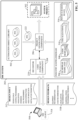
- FIG. 7 is a diagram illustrating commissioning of a system project 302.
- Project deployment component 208 can compile or otherwise translate a completed system project 302 into one or more executable files or configuration files that can be stored and executed on respective target industrial devices of the automation system (e.g., industrial controllers 118, HMI terminals 114 or other types of visualization systems, motor drives 710, telemetry devices, vision systems, safety relays, etc.).
- control program development platforms require the developer to specify the type of industrial controller (e.g., the controller's model number) on which the control program will run prior to development, thereby binding the control programming to a specified controller. Controller-specific guardrails are then enforced during program development which limit how the program is developed given the capabilities of the selected controller.
- some embodiments of the IDE system 202 can abstract project development from the specific controller type, allowing the designer to develop the system project 302 as a logical representation of the automation system in a manner that is agnostic to where and how the various control aspects of system project 302 will run.
- system project 302 Once project development is complete and system project 302 is ready for commissioning, the user can specify (via user interface component 204) target devices on which respective aspects of the system project 302 are to be executed.
- an allocation engine of the project deployment component 208 will translate aspects of the system project 302 to respective executable files formatted for storage and execution on their respective target devices.
- system project 302 may include - among other project aspects - control code, visualization screen definitions, and motor drive parameter definitions.
- a user can identify which target devices- including an industrial controller 118, an HMI terminal 114, and a motor drive 710 - are to execute or receive these respective aspects of the system project 302.
- Project deployment component 208 can then translate the controller code defined by the system project 302 to a control program file 702 formatted for execution on the specified industrial controller 118 and send this control program file 702 to the controller 118 (e.g., via plant network 116).
- project deployment component 208 can translate the visualization definitions and motor drive parameter definitions to a visualization application 704 and a device configuration file 708, respectively, and deploy these files to their respective target devices for execution and/or device configuration.
- project deployment component 208 performs any conversions necessary to allow aspects of system project 302 to execute on the specified devices. Any inherent relationships, handshakes, or data sharing defined in the system project 302 are maintained regardless of how the various elements of the system project 302 are distributed. In this way, embodiments of the IDE system 202 can decouple the project from how and where the project is to be run. This also allows the same system project 302 to be commissioned at different plant facilities having different sets of control equipment. That is, some embodiments of the IDE system 202 can allocate project code to different target devices as a function of the particular devices found on-site. IDE system 202 can also allow some portions of the project file to be commissioned as an emulator or on a cloud-based controller.
- IDE system 202 can actively connect to the plant network 116 and discover available devices, ascertain the control hardware architecture present on the plant floor, infer appropriate target devices for respective executable aspects of system project 302, and deploy the system project 302 to these selected target devices.
- IDE system 202 can also connect to remote knowledgebases (e.g., web-based or cloud-based knowledgebases) to determine which discovered devices are out of date or require firmware upgrade to properly execute the system project 302. In this way, the IDE system 202 can serve as a link between device vendors and a customer's plant ecosystem via a trusted connection in the cloud.
- Copies of system project 302 can be propagated to multiple plant facilities having varying equipment configurations using smart propagation, whereby the project deployment component 208 intelligently associates project components with the correct industrial asset or control device even if the equipment on-site does not perfectly match the defined target (e.g., if different pump types are found at different sites). For target devices that do not perfectly match the expected asset, project deployment component 208 can calculate the estimated impact of running the system project 302 on non-optimal target equipment and generate warnings or recommendations for mitigating expected deviations from optimal project execution.
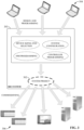
- FIG. 8 is a diagram illustrating an example architecture in which cloud-based IDE services 802 are used to develop and deploy industrial applications to a plant environment.
- the industrial environment includes one or more industrial controllers 118, HMI terminals 114, motor drives 710, servers 801 running higher level applications (e.g., ERP, MES, etc.), and other such industrial assets.
- These industrial assets are connected to a plant network 116 (e.g., a common industrial protocol network, an Ethernet/IP network, etc.) that facilitates data exchange between industrial devices on the plant floor.
- Plant network 116 may be a wired or a wireless network.
- the high-level servers 810 reside on a separate office network 108 that is connected to the plant network 116 (e.g., through a router 808 or other network infrastructure device).
- IDE system 202 resides on a cloud platform 806 and executes as a set of cloud-based IDE service 802 that are accessible to authorized remote client devices 504.
- Cloud platform 806 can be any infrastructure that allows shared computing services (such as IDE services 802) to be accessed and utilized by cloud-capable devices.
- Cloud platform 806 can be a public cloud accessible via the Internet by devices 504 having Internet connectivity and appropriate authorizations to utilize the IDE services 802.
- cloud platform 806 can be provided by a cloud provider as a platform-as-a-service (PaaS), and the IDE services 802 can reside and execute on the cloud platform 806 as a cloud-based service.
- PaaS platform-as-a-service
- cloud platform 806 can be a private cloud operated internally by the industrial enterprise (the owner of the plant facility).
- An example private cloud platform can comprise a set of servers hosting the IDE services 802 and residing on a corporate network protected by a firewall.
- Cloud-based implementations of IDE system 202 can facilitate collaborative development by multiple remote developers who are authorized to access the IDE services 802.
- the project 302 can be commissioned to the plant facility via a secure connection between the office network 108 or the plant network 116 and the cloud platform 806.
- the industrial IDE services 802 can translate system project 302 to one or more appropriate executable files - control program files 702, visualization applications 704, device configuration files 708, system configuration files 812 - and deploy these files to the appropriate devices in the plant facility to facilitate implementation of the automation project.
- FIG. 9 is an illustration of an example automation object 222 that has been integrated into the project data model 602 of a system project 302.
- a system project 302 can incorporate instances of automation objects 222 that serve as programmatic representations of industrial assets, processes, or other industrial entities.
- Assets that can be represented by a given automation object 222 can include device-level assets (e.g., motor drives, valves, pumps, etc.) as well as machine-level assets (stamping presses, tanks, tooling stations, etc.).
- An automation object 222 can represent an off-the-shelf industrial device or machine offered by device or equipment vendors, or may comprise custom automation objects 222 representing custom-built machines provided by an OEM or another type of machine builder.
- the project data model 602 can define hierarchical relationships between multiple automation objects 222 that are integrated as part of the system project 302. These hierarchical relationships can represent the physical and/or functional relationships between the represented assets.
- a process automation object 222 representing a batch process may be defined as a parent object to a number of child automation objects 222 representing devices and equipment that carry out the process, such as tanks, pumps, and valves.
- an automation object 222 representing a machine or production line can be defined as a parent object, under which are defined a number of child automation objects 222 representing the workstations or sub-machines within the machine or production line.
- These child automation objects 222 can themselves have a number of child automation objects 222 representing the device-level assets that make up these workstations or sub-machines.
- Each industrial object 222 can serve similar functions to those of data tags that serve as containers for input data received from, and output data sent to, its corresponding industrial asset (e.g., digital and analog data values received from the asset for processing by the system project 302, as well as digital and analog values generated by the system project 302 and sent to the asset).
- each industrial object 222 comprises a number of programmatic attributes relating to the industrial asset being represented, examples of which are discussed above in connection with FIG. 4 . These attributes can include, for example, control logic that can be executed as part of the system project 302 to monitor and control the represented assets.
- This associated control logic can be pre-developed to exchange input and output data with its associated industrial asset via defined input and output tags corresponding to the asset's physical inputs and outputs (that is, the asset's digital and analog I/O).
- the object's control logic can process inputs received from the asset and generate outputs directed to the asset based on results of this processing.
- control logic associated with respective different automation objects 222 defined by the project data model 602 as having a hierarchical relationship with one another can interact or cooperate based on these defined relationships. For example, based on a defined hierarchical relationship between a first automation object 222 representing a tank (defined as a parent object) and a second automation object 222 representing a valve associated with the tank (defined as a child of the first object), the system project 302 can link the two sets of control logic associated with the first and second automation objects 222, respectively, so that the control logic associated with the two automation objects 222 performs coordinated monitoring and control of the machine. Linking the two sets of control logic in this manner can comprise, for example, linking data tags of the child object 222 with corresponding data tags of the parent object 222 in accordance with the hierarchical relationship defined by the model 602.
- Industrial object 222 can also include associated HMI objects that can be used by a visualization system (e.g., an HMI application, a 2D or 3D augmented reality or virtual reality system, etc.) to render an animated graphical representation of the asset.
- HMI objects can include one or more HMI interface screens designed to render information about the asset (e.g., a reporting screen that renders statistical or operational data for the asset, a screen that renders an animated graphical representation of the asset, etc.), individual graphical objects representing the asset that can be imported into an industrial visualization application, or other such objects.
- the automation object 222 can also include analytic scripts designed to analyze data generated by the asset to produce insights into the asset's performance or health.
- Example analytics that can be performed by an automation object's analytic scripts can include, but are not limited to, assessments of the asset's current health and predicted future health (e.g., determinations of the asset's predicted time to failure), determinations of when the asset requires maintenance, or other such metrics.
- the analytics scripts can be designed to interface with known data items generated by the industrial asset (e.g., data tags that are specific to the asset) so that the data associated with these data items can be processed by the scripts.
- the automation object 222 can also define alarm information associated with the industrial asset.
- This alarm information can include definitions of the conditions that trigger the alarm (e.g., when a specified data item representing an operational metric of the asset falls outside a defined range of normal behavior, when a state of a specified digital tag satisfies an alarm condition, etc.) as well as an alarm message to be rendered in response to the alarm trigger.
- This alarm information can be referenced by a visualization system (e.g., an HMI application, an augmented reality or virtual realty system, etc.), which can render alarm messages for the industrial asset based on the alarm definitions defined by the automation object 222.
- automation object 222 can also define test properties as part of a global testing framework supported by the IDE system 202. These test properties can include object-specific test scripts designed to test and debug the automation object 222 and associated aspects of system project 302 that reference the object 222.
- the object's test properties can also include object-specific test scenario definitions that define one or more test scenarios that may beneficially be run against the automation object 222 and associated project elements that reference the object 222.
- the test scenario definitions can be pre-designed based on industrial expertise regarding the industrial asset or process represented by the automation object 222.
- the test properties associated with automation objects 222 can mitigate the need to write test scripts to test and debug the system project 302.
- FIG. 10 is a diagram illustrating testing of an example system project 302 by the IDE system's project testing component 210 using test scripts 1002 bundled with an automation object 222.
- Automation objects 222 can be provided with pre-bundled test scripts 1002 and/or definitions of test scenarios 1004 that are specific to the type of industrial asset represented by the automation object 222.
- the IDE system's project testing component 210 can execute test scripts 1002 associated with one or more selected automation objects 222 as appropriate to verify proper responses of the system project 302, thereby validating the project.
- test scripts 1002 can define simulated test inputs 1012 to be provided to the automation object 222 and/or associated project code in which the object 222 is used, as well as expected responses of the automation object 222 and its associated project code to the simulated inputs 1012.
- project testing component 210 can execute one or more test scripts 1002 associated with respective one or more automation objects 222 against system project 302. Execution of the test scripts 1002 can involve, for example, feeding simulated test inputs 1012 to control code or other elements of system project 302 according to a sequence defined by the test scripts 1002, setting values of digital or analog program variables defined by the system project 302 according to a defined sequence, initiating control routines of the system project 302 according to a defined sequence, testing animation objects or other visualization elements defined by the system project 302, verifying data linkages between control routines, verifying relationships between program elements and drawing elements, confirming that device configuration settings or parameter values are appropriate for a given industrial application being carried out by the system project 302, or otherwise interacting with system project 302 according to testing procedures defined by the test scripts 1002.
- project testing component 210 can execute the one or more test scripts 1002 in accordance with each defined test scenario 1004 in sequence in order to comprehensively validate proper operation of the system project 302 across all platforms (control programming, visualization configuration, drawings, device configurations, etc.).
- object 222a is an instance of an automation object 222 that has been selected and added to the system project 302 by the developer.
- the project generation component 206 may also automatically select and add automation objects 222 to the project 302 based on inferences about the automation system for which the project 302 is being developed (e.g., based on design goals or engineering drawings submitted to the system 202).
- a developer may, for example, create a custom shared library 502b that comprises many of the same automation objects 222 that are available in the common shared library 502a, but which modifies selected attributes of one or more of the objects 222 relative to the vendor-provided versions (e.g., via submission of automation object edits 1102 as discussed above in connection with FIG. 11 ).
- a developer may create a custom shared library 502b that expands the set of automation objects 222 that are available in the common shared library 502b by adding new custom objects 222 that represent custom or proprietary industrial assets that are in service at the customer's plant facility.
- Customer 2 has created a single custom shared library 502d, while Customer 1 has created two different custom shared libraries 502b and 502c.
- the first custom shared library 502b has been created as a modified version of the vendor-provided shared library 502a.
- the second custom shared library 502c has been created as a modified version of the first custom shared library 502b; e.g., by modifying attributes of one or more objects 222 stored in the first custom library 502b or by adding new custom objects 222 to the set of objects available in the first custom library 502b.
- custom shared libraries 502 can be created in this manner for a given customer entity, and each shared library 502 can be referenced by one or more system projects 302 that are either stored on the cloud platform on which the IDE system 202 executes or stored locally on client devices 504 that remotely access the IDE services.
- the system 202 allows developers to set the scope of each custom library 502, such that access to a custom shared library 502 can be regulated according to industrial enterprise, plant facility, user role, or individual user identities.
- a system project 302 references a shared library 502, as defined by the project's shared library mapping 1602, the IDE system 202 will deliver notifications to the project 302 to alert the project developer of edits, additions, or updates that have been submitted to the shared library 502.
- the user interface component 204 will render an edit notification on the project 302 when another user submits an edit to the content of the shared library 502, as discussed above in connection with FIG. 14 .
- These edits can comprise, for example, edits to one or more attributes of automation objects 222, or edits to code modules, stored in the shared library 502.
- the edit notification can display, within the IDE development environment rendered on the recipient's client device 504, information about the edit, including an identity of the automation object 222 that has been modified, a summary of which object attributes have been modified (including the new values of the attributes), an identification of the shared library in which the affected automation object resides, or other such information.
- the edit notification may also include design notes that were attached to the edit 1102 by the developer who submitted the edit 1102. These design notes can be used to convey the developer's reason for the edit, an explanation of design scenarios in which the edited object 222 should be used, or other such information.
- the collaboration management component 212 may also analyze the recipient's system project 302 in view of the object edit to determine possible impacts on the recipient's system project 302 - or impacts on operation of the automation system to be monitored and controlled by the project 302 - if the edit were to be propagated to instances of the object within the project 302.
- the edit notification can include a summary of these possible impacts for review by the user. This analysis may determine, for example, whether implementation of the edit will negatively impact, or improve, a key performance indicator of the system project 302 (e.g., product throughput, machine downtime, device lifecycle, energy consumption, etc.).
- the recipient can elect to either allow the corresponding object updates 1402 to be propagated to instances of the affected object within the recipient's own system project 302, or to decline implementation of the updates 1402 within their project 302, as discussed above in connection with FIG. 14 .
- the system 202 can allow the recipient to partially or selectively implement the object updates 1402 by opting to propagate the updates 1402 only to a selected subset of instances of the affected object within the recipient's project 302. In this way, the IDE system 202 supports instantiation of multiple different versions of a given automation object 222 within a system project 302.
- the user interface component 204 can also deliver notifications to projects 302 that reference a shared library 502 when new objects or code modules are added to the library 502 by other developers. These notifications can include information about the newly added object 222, including but not limited to an industrial asset represented by the new object 222, key attributes associated with the object 222, design scenarios in which the new object 222 is intended to be used, or other such information.
- the user interface component 204 can render the library update notifications described above in a browsable format. For example, if updates are available for one or more of the shared libraries 302 referenced by a developer's system project 302, the IDE development interface may display an icon indicating that the user's project 302 is not synchronize with one or more of the shared libraries 502. Selection of this icon can render a list of the shared libraries 502 that are referenced by the project 302 and which have updates that have not been synchronized to the developer's project 302. The user interface component 204 can allow the user to browse the available updates via interaction with this list; e.g., by selecting a library from the list to render the updates that are available in that library 502.
- the user can then review these pending library updates 1402 and select which of the updates 1402 are to be synchronized to the user's own project 302.
- the user can further opt, for each object update, either to apply the update 1402 to all instances of the affected automation object 222 or to apply the update to a selected subset of instances within the project 302.
- the IDE system 202 affords the user a high degree of granularity with regard to synchronization of edits submitted to shared libraries 502.
- example shared library architecture illustrated in FIG. 16 depicts cross-sharing of libraries 502 by system projects 302 that are stored locally on client devices 504 for local development
- the shared library features described above are also applicable in scenarios in which the system projects 302 are stored on cloud storage for remote collaborative development.
- IDE system 202 can also allow developers to create personal library content derived from existing content of shared libraries 502. As described above with reference to FIG. 15 , developers can create a custom library as a modified version of a shared library 502. Although FIG. 15 depict the resulting new libraries as being sharable libraries that can be referenced by multiple authorized projects 302, the IDE system 202 can also allow a developer to create a personal custom library in this manner, such that the personal library can be referenced only by the developer's own system project 302.
- a custom library can be created by modifying attributes of one or more objects 222 stored in an existing shared library 502 or by adding new custom objects 222 to the set of objects available in the shared library, and saving the resulting modified library 502 as a new custom library (leaving the original shared library unmodified).
- the resulting custom library can be set to be a sharable library or can be saved as a personal library referenced only by the developer's own system project 302.
- FIG. 17a illustrates a first part of an example methodology for propagating edits to an automation object to instances of the object used in one or more system projects.
- industrial design data is received at an industrial IDE system from an instance of a development platform rendered on a client device by the industrial IDE system.
- the industrial design data can be submitted in the form of one or more of industrial controller programming (e.g., ladder logic, sequential function charts, scripted control code such as an industrial DSL, etc.), HMI screen development input, industrial device or equipment selections, engineering drawing input, etc.
- an industrial automation system project is generated based on the design data received at step 1702.
- at least one instance of an automation object selected from a library of available automation objects can be included in the project.
- the automation objects are building blocks for the industrial automation system project and represent various types of real-world industrial assets or processes, including but not limited to pumps, tanks, values, motors, motor drives (e.g., variable frequency drives), industrial robots, actuators (e.g., pneumatic or hydraulic actuators), or other such assets.
- the automation objects are associated with various attributes or properties as a function of their represented asset or process (e.g., control code, visualization objects or interfaces, test scripts, security features or protocols, etc.).
- the edit input may define a modification to one or more of the control code, visualization definitions, testing scripts, security protocols, or other attributes of the object.
- the edit may be received from another instance of the development platform with authorization to access the library of automation objects.
- the automation object library serves as a shared library that can be accessed by multiple system projects as a source of vendor-provided or user-defined automation objects. If object edit input is received (YES at step 1706), the methodology proceeds to step 1508, where the modifications are applied to the one or more attributes of the selected automation object in the library.
- Embodiments, systems, and components described herein, as well as control systems and automation environments in which various aspects set forth in the subject specification can be carried out can include computer or network components such as servers, clients, programmable logic controllers (PLCs), automation controllers, communications modules, mobile computers, on-board computers for mobile vehicles, wireless components, control components and so forth which are capable of interacting across a network.
- Computers and servers include one or more processors-electronic integrated circuits that perform logic operations employing electric signals-configured to execute instructions stored in media such as random access memory (RAM), read only memory (ROM), a hard drives, as well as removable memory devices, which can include memory sticks, memory cards, flash drives, external hard drives, and so on.
- the term PLC or automation controller as used herein can include functionality that can be shared across multiple components, systems, and/or networks.
- one or more PLCs or automation controllers can communicate and cooperate with various network devices across the network. This can include substantially any type of control, communications module, computer, Input/Output (I/O) device, sensor, actuator, and human machine interface (HMI) that communicate via the network, which includes control, automation, and/or public networks.
- the PLC or automation controller can also communicate to and control various other devices such as standard or safety-rated I/O modules including analog, digital, programmed/intelligent I/O modules, other programmable controllers, communications modules, sensors, actuators, output devices, and the like.
- the network can include public networks such as the internet, intranets, and automation networks such as control and information protocol (CIP) networks including DeviceNet, ControlNet, safety networks, and Ethernet/IP. Other networks include Ethernet, DH/DH+, Remote I/O, Fieldbus, Modbus, Profibus, CAN, wireless networks, serial protocols, and so forth.
- the network devices can include various possibilities (hardware and/or software components). These include components such as switches with virtual local area network (VLAN) capability, LANs, WANs, proxies, gateways, routers, firewalls, virtual private network (VPN) devices, servers, clients, computers, configuration tools, monitoring tools, and/or other devices.
- VLAN virtual local area network
- WANs wide area network
- proxies gateways
- routers virtual private network
- VPN virtual private network
- FIGs. 18 and 19 are intended to provide a brief, general description of a suitable environment in which the various aspects of the disclosed subject matter may be implemented. While the embodiments have been described above in the general context of computer-executable instructions that can run on one or more computers, those skilled in the art will recognize that the embodiments can be also implemented in combination with other program modules and/or as a combination of hardware and software.
- program modules include routines, programs, components, data structures, etc., that perform particular tasks or implement particular abstract data types.
- inventive methods can be practiced with other computer system configurations, including single-processor or multiprocessor computer systems, minicomputers, mainframe computers, Internet of Things (IoT) devices, distributed computing systems, as well as personal computers, hand-held computing devices, microprocessor-based or programmable consumer electronics, and the like, each of which can be operatively coupled to one or more associated devices.
- IoT Internet of Things
- the illustrated embodiments herein can be also practiced in distributed computing environments where certain tasks are performed by remote processing devices that are linked through a communications network.
- program modules can be located in both local and remote memory storage devices.
- Computer-readable storage media or machine-readable storage media can be any available storage media that can be accessed by the computer and includes both volatile and nonvolatile media, removable and non-removable media.
- Computer-readable storage media or machine-readable storage media can be implemented in connection with any method or technology for storage of information such as computer-readable or machine-readable instructions, program modules, structured data or unstructured data.
- Computer-readable storage media can include, but are not limited to, random access memory (RAM), read only memory (ROM), electrically erasable programmable read only memory (EEPROM), flash memory or other memory technology, compact disk read only memory (CD-ROM), digital versatile disk (DVD), Blu-ray disc (BD) or other optical disk storage, magnetic cassettes, magnetic tape, magnetic disk storage or other magnetic storage devices, solid state drives or other solid state storage devices, or other tangible and/or non-transitory media which can be used to store desired information.
- RAM random access memory
- ROM read only memory
- EEPROM electrically erasable programmable read only memory
- flash memory or other memory technology
- CD-ROM compact disk read only memory
- DVD digital versatile disk
- Blu-ray disc (BD) or other optical disk storage magnetic cassettes, magnetic tape, magnetic disk storage or other magnetic storage devices, solid state drives or other solid state storage devices, or other tangible and/or non-transitory media which can be used to store desired information.
- tangible or “non-transitory” herein as applied to storage, memory or computer-readable media, are to be understood to exclude only propagating transitory signals per se as modifiers and do not relinquish rights to all standard storage, memory or computer-readable media that are not only propagating transitory signals per se.
- Computer-readable storage media can be accessed by one or more local or remote computing devices, e.g., via access requests, queries or other data retrieval protocols, for a variety of operations with respect to the information stored by the medium.
- Communications media typically embody computer-readable instructions, data structures, program modules or other structured or unstructured data in a data signal such as a modulated data signal, e.g., a carrier wave or other transport mechanism, and includes any information delivery or transport media.
- modulated data signal or signals refers to a signal that has one or more of its characteristics set or changed in such a manner as to encode information in one or more signals.
- communication media include wired media, such as a wired network or direct-wired connection, and wireless media such as acoustic, RF, infrared and other wireless media.
- the example environment 1800 for implementing various embodiments of the aspects described herein includes a computer 1802, the computer 1802 including a processing unit 1804, a system memory 1806 and a system bus 1808.
- the system bus 1808 couples system components including, but not limited to, the system memory 1806 to the processing unit 1804.
- the processing unit 1804 can be any of various commercially available processors. Dual microprocessors and other multi-processor architectures can also be employed as the processing unit 1804.
- the system bus 1808 can be any of several types of bus structure that can further interconnect to a memory bus (with or without a memory controller), a peripheral bus, and a local bus using any of a variety of commercially available bus architectures.
- the system memory 1806 includes ROM 1810 and RAM 1812.
- a basic input/output system (BIOS) can be stored in a non-volatile memory such as ROM, erasable programmable read only memory (EPROM), EEPROM, which BIOS contains the basic routines that help to transfer information between elements within the computer 1802, such as during startup.
- the RAM 1812 can also include a highspeed RAM such as static RAM for caching data.
- the computer 1802 further includes an internal hard disk drive (HDD) 1814 (e.g., EIDE, SATA), one or more external storage devices 1816 (e.g., a magnetic floppy disk drive (FDD) 1816, a memory stick or flash drive reader, a memory card reader, etc.) and an optical disk drive 1820 (e.g., which can read or write from a CD-ROM disc, a DVD, a BD, etc.).
- HDD 1814 e.g., EIDE, SATA
- external storage devices 1816 e.g., a magnetic floppy disk drive (FDD) 1816, a memory stick or flash drive reader, a memory card reader, etc.
- an optical disk drive 1820 e.g., which can read or write from a CD-ROM disc, a DVD, a BD, etc.
- the internal HDD 1814 is illustrated as located within the computer 1802, the internal HDD 1814 can also be configured for external use in a suitable chassis (not shown).
- the HDD 1814, external storage device(s) 1816 and optical disk drive 1820 can be connected to the system bus 1808 by an HDD interface 1824, an external storage interface 1826 and an optical drive interface 1828, respectively.
- the interface 1824 for external drive implementations can include at least one or both of Universal Serial Bus (USB) and Institute of Electrical and Electronics Engineers (IEEE) 1394 interface technologies. Other external drive connection technologies are within contemplation of the embodiments described herein.
- the drives and their associated computer-readable storage media provide nonvolatile storage of data, data structures, computer-executable instructions, and so forth.
- the drives and storage media accommodate the storage of any data in a suitable digital format.
- computer-readable storage media refers to respective types of storage devices, it should be appreciated by those skilled in the art that other types of storage media which are readable by a computer, whether presently existing or developed in the future, could also be used in the example operating environment, and further, that any such storage media can contain computer-executable instructions for performing the methods described herein.
- a number of program modules can be stored in the drives and RAM 1812, including an operating system 1830, one or more application programs 1832, other program modules 1834 and program data 1836. All or portions of the operating system, applications, modules, and/or data can also be cached in the RAM 1812.
- the systems and methods described herein can be implemented utilizing various commercially available operating systems or combinations of operating systems.
- Computer 1802 can optionally comprise emulation technologies.
- a hypervisor (not shown) or other intermediary can emulate a hardware environment for operating system 1830, and the emulated hardware can optionally be different from the hardware illustrated in FIG. 18 .
- operating system 1830 can comprise one virtual machine (VM) of multiple VMs hosted at computer 1802.
- VM virtual machine
- operating system 1830 can provide runtime environments, such as the Java runtime environment or the .NET framework, for application programs 1832. Runtime environments are consistent execution environments that allow application programs 1832 to run on any operating system that includes the runtime environment.
- operating system 1830 can support containers, and application programs 1832 can be in the form of containers, which are lightweight, standalone, executable packages of software that include, e.g., code, runtime, system tools, system libraries and settings for an application.
- computer 1802 can be enable with a security module, such as a trusted processing module (TPM).
- TPM trusted processing module
- boot components hash next in time boot components, and wait for a match of results to secured values, before loading a next boot component.
- This process can take place at any layer in the code execution stack of computer 1802, e.g., applied at the application execution level or at the operating system (OS) kernel level, thereby enabling security at any level of code execution.
- OS operating system
- a user can enter commands and information into the computer 1802 through one or more wired/wireless input devices, e.g., a keyboard 1838, a touch screen 1840, and a pointing device, such as a mouse 1842.
- Other input devices can include a microphone, an infrared (IR) remote control, a radio frequency (RF) remote control, or other remote control, a joystick, a virtual reality controller and/or virtual reality headset, a game pad, a stylus pen, an image input device, e.g., camera(s), a gesture sensor input device, a vision movement sensor input device, an emotion or facial detection device, a biometric input device, e.g., fingerprint or iris scanner, or the like.
- IR infrared
- RF radio frequency
- input devices are often connected to the processing unit 1804 through an input device interface 1844 that can be coupled to the system bus 1808, but can be connected by other interfaces, such as a parallel port, an IEEE 1394 serial port, a game port, a USB port, an IR interface, a BLUETOOTH ® interface, etc.
- an input device interface 1844 can be coupled to the system bus 1808, but can be connected by other interfaces, such as a parallel port, an IEEE 1394 serial port, a game port, a USB port, an IR interface, a BLUETOOTH ® interface, etc.
- a monitor 1844 or other type of display device can be also connected to the system bus 1808 via an interface, such as a video adapter 1846.
- a computer typically includes other peripheral output devices (not shown), such as speakers, printers, etc.
- the computer 1802 can operate in a networked environment using logical connections via wired and/or wireless communications to one or more remote computers, such as a remote computer(s) 1848.
- the remote computer(s) 1848 can be a workstation, a server computer, a router, a personal computer, portable computer, microprocessor-based entertainment appliance, a peer device or other common network node, and typically includes many or all of the elements described relative to the computer 1802, although, for purposes of brevity, only a memory/storage device 1850 is illustrated.
- the logical connections depicted include wired/wireless connectivity to a local area network (LAN) 1852 and/or larger networks, e.g., a wide area network (WAN) 1854.
- LAN and WAN networking environments are commonplace in offices and companies, and facilitate enterprise-wide computer networks, such as intranets, all of which can connect to a global communications network, e.g., the Internet.
- the computer 1802 When used in a LAN networking environment, the computer 1802 can be connected to the local network 1852 through a wired and/or wireless communication network interface or adapter 1856.
- the adapter 1856 can facilitate wired or wireless communication to the LAN 1852, which can also include a wireless access point (AP) disposed thereon for communicating with the adapter 1856 in a wireless mode.
- AP wireless access point
- the computer 1802 can include a modem 1858 or can be connected to a communications server on the WAN 1854 via other means for establishing communications over the WAN 1854, such as by way of the Internet.
- the modem 1858 which can be internal or external and a wired or wireless device, can be connected to the system bus 1808 via the input device interface 1842.
- program modules depicted relative to the computer 1802 or portions thereof can be stored in the remote memory/storage device 1850. It will be appreciated that the network connections shown are example and other means of establishing a communications link between the computers can be used.
- the computer 1802 can access cloud storage systems or other network-based storage systems in addition to, or in place of, external storage devices 1816 as described above.
- a connection between the computer 1802 and a cloud storage system can be established over a LAN 1852 or WAN 1854 e.g., by the adapter 1856 or modem 1858, respectively.
- the external storage interface 1826 can, with the aid of the adapter 1856 and/or modem 1858, manage storage provided by the cloud storage system as it would other types of external storage.
- the external storage interface 1826 can be configured to provide access to cloud storage sources as if those sources were physically connected to the computer 1802.
- the computer 1802 can be operable to communicate with any wireless devices or entities operatively disposed in wireless communication, e.g., a printer, scanner, desktop and/or portable computer, portable data assistant, communications satellite, any piece of equipment or location associated with a wirelessly detectable tag (e.g., a kiosk, news stand, store shelf, etc.), and telephone.
- any wireless devices or entities operatively disposed in wireless communication e.g., a printer, scanner, desktop and/or portable computer, portable data assistant, communications satellite, any piece of equipment or location associated with a wirelessly detectable tag (e.g., a kiosk, news stand, store shelf, etc.), and telephone.
- This can include Wireless Fidelity (Wi-Fi) and BLUETOOTH ® wireless technologies.
- the communication can be a predefined structure as with a conventional network or simply an ad hoc communication between at least two devices.
- the sample computing environment 1900 includes a communication framework 1906 that can be employed to facilitate communications between the client(s) 1902 and the server(s) 1904.
- the client(s) 1902 are operably connected to one or more client data store(s) 1908 that can be employed to store information local to the client(s) 1902.
- the server(s) 1904 are operably connected to one or more server data store(s) 1910 that can be employed to store information local to the servers 1904.
- Computer readable media can include but are not limited to magnetic storage devices (e.g., hard disk, floppy disk, magnetic strips...), optical disks [e.g., compact disk (CD), digital versatile disk (DVD)...], smart cards, and flash memory devices (e.g., card, stick, key drive).
- magnetic storage devices e.g., hard disk, floppy disk, magnetic strips
- optical disks e.g., compact disk (CD), digital versatile disk (DVD)...
- smart cards e.g., card, stick, key drive
Landscapes
- Engineering & Computer Science (AREA)
- General Engineering & Computer Science (AREA)
- Physics & Mathematics (AREA)
- General Physics & Mathematics (AREA)
- Automation & Control Theory (AREA)
- Software Systems (AREA)
- Manufacturing & Machinery (AREA)
- Quality & Reliability (AREA)
- Theoretical Computer Science (AREA)
- Computer Security & Cryptography (AREA)
- Stored Programmes (AREA)
Claims (15)
- Système (202) conçu pour le développement d'applications industrielles, comprenant les éléments suivants :une mémoire (220, 1806, 1814, 1816, 1822) qui stocke des composants exécutables et des bibliothèques partagées (502) d'objets d'automatisation (222) représentant des actifs industriels respectifs (120, 402), les objets d'automatisation ayant des attributs programmatiques respectifs associés aux actifs industriels ; etun processeur (218,1804), couplé de manière opérationnelle à la mémoire, qui exécute les composants exécutables, les composants exécutables comprenant les éléments suivants :un composant d'interface utilisateur (204) configuré pour présenter des interfaces d'environnement de développement intégré (IDE) et pour recevoir, par interaction avec les interfaces IDE, des données de conception (512) qui définissent les aspects d'un projet d'automatisation industrielle ; etun composant de génération de projet (206) configuré pour générer des données de projet de système sur la base des données de conception, les données de projet de système comprenant des instances d'un ou de plusieurs objets d'automatisation stockés dans une ou plusieurs bibliothèques partagées auxquelles le projet de système (302) est associé,dans lequelles données du projet de système définissent un projet de système comprenant au moins un programme de commande industrielle exécutable (702), une application de visualisation industrielle (704) ou des données de configuration d'un dispositif industriel (708), etle composant de génération de projet est configuré pour, en réponse à la réception d'une modification d'un objet d'automatisation dans une bibliothèque des bibliothèques partagées :modifier (1708) l'objet automatisé dans la bibliothèque des bibliothèques partagées en fonction de la modification ;déterminer (1710) si une instance de l'objet d'automatisation qui a été modifiée est incluse dans les données de projet du système,faire en sorte que le composant d'interface utilisateur rende (1712), par l'intermédiaire d'une ou plusieurs des interfaces IDE, une notification indiquant que l'objet d'automatisation a été modifié dans la bibliothèque, eten réponse à la réception (1714), après interaction avec l'une des interfaces IDE, d'une demande de synchronisation de la modification, modifier (1716) l'instance de l'objet d'automatisation dans le projet de système conformément à la modification.
- Système selon la revendication 1, dans lequel la notification comprend au moins une identité de l'objet d'automatisation sur lequel porte la modification, un attribut de l'objet d'automatisation qui est modifié par la modification, ou une identité de la bibliothèque dans laquelle réside l'objet d'automatisation.
- Système selon les revendications 1 ou 2, dans lequel la notification comprend une icône graphique superposée à une représentation graphique de l'instance de l'objet d'automatisation dans le projet de système.
- Système selon l'une des revendications 1 à 3, dans lequel les données du projet de système comprennent une pluralité d'instances de l'objet d'automatisation incluant l'instance de l'objet d'automatisation, et dans lequel le composant de génération de projet est configuré pour, conformément à une demande de l'utilisateur reçue via une interaction avec une ou plusieurs interfaces IDE, synchroniser la modification sur un premier sous-ensemble sélectionné par l'utilisateur de la pluralité d'instances de l'objet d'automatisation inférieur à un ensemble total d'instances de l'objet d'automatisation inclus dans le projet de système, et laisser un deuxième sous-ensemble restant de la pluralité d'instances de l'objet d'automatisation non modifié.
- Système selon l'une des revendications 1 à 4, dans lequel le composant de génération de projet est en outre configuré pour, en réponse à la réception d'une instruction via l'interaction avec l'une des interfaces IDE, créer une bibliothèque personnalisée d'objets d'automatisation en tant que version modifiée de l'une des bibliothèques partagées ; et/ou
dans lequel le composant de génération de projet est configuré pour, conformément à l'instruction, définir la bibliothèque personnalisée comme l'une des bibliothèques partagées accessibles aux autres projets du système ou comme une bibliothèque personnelle accessible exclusivement au projet du système. - Système selon la revendication 5, dans lequel le composant de génération de projet est configuré pour rendre la bibliothèque personnalisée accessible exclusivement à d'autres projets de système associés à une même entreprise industrielle que celle du projet de système.
- Système selon l'une des revendications 1 à 6, dans lequel le projet de système est mis en correspondance avec plusieurs bibliothèques des bibliothèques partagées.
- Système selon l'une des revendications 1 à 7, dans lequel l'édition modifie un attribut de l'objet d'automatisation, l'attribut comprenant au moins l'un des codes de commande pour la surveillance et le commande d'un bien industriel représenté par l'objet d'automatisation, un objet de visualisation qui définit une visualisation graphique du bien industriel, une définition d'alarme pour le bien industriel, une caractéristique de sécurité du bien industriel, un protocole de sécurité du bien industriel, un script de test configuré pour valider le fonctionnement de l'objet d'automatisation au sein du projet de système, ou un script analytique configuré pour effectuer une analyse sur les données générées par le bien industriel.
- Système selon l'une des revendications 1 à 8, dans lequel les objets d'automatisation représentent, en tant qu'actifs industriels, au moins l'un des éléments suivants : un processus industriel, un dispositif de commande, un programme de commande, une étiquette dans le programme de commande, une machine, un moteur, une commande de moteur, un dispositif de télémétrie, un réservoir, une vanne, une pompe, un dispositif de sécurité industriel, un robot industriel ou un actionneur.
- Procédé mis en œuvre par ordinateur pour développer des applications industrielles, comprenant les opérations suivantes :le rendu, à l'aide d'un système (202) comprenant un processeur (218, 1804), des interfaces d'environnement de développement intégré (IDE) sur un dispositif client ;la réception (1702), par le système après interaction avec les interfaces IDE, des données de conception (512) qui définissent les aspects d'un projet de commande et de surveillance industriels ;la génération (1704), à l'aide du système, des données de projet de système fondées sur l'entrée de conception, les données de projet de système comprenant des instances d'un ou plusieurs objets d'automatisation (222) stockés dans une ou plusieurs bibliothèques partagées (512) d'objets d'automatisation, la génération comprenant la génération d'au moins un programme de commande industrielle exécutable (702), une application de visualisation industrielle (704) ou des données de configuration de dispositif industriel (708) ; et en réponse à la réception (1706) d'une modification d'un objet d'automatisation dans une bibliothèque des bibliothèques partagées :modifier (1708) l'objet d'automatisation dans la bibliothèque des bibliothèques partagées conformément à la modification ;déterminer (1710), à l'aide du système, si une instance de l'objet d'automatisation qui a été modifiée est incluse dans les données de projet du système,rendre (1712), à l'aide du système par l'intermédiaire d'une ou plusieurs interfaces IDE, une notification indiquant que l'objet d'automatisation a été édité dans la bibliothèque, eten réponse à la réception (1714), après interaction avec l'une des interfaces IDE, d'une demande de synchronisation de la modification, modifier (1716), à l'aide du système, l'instance de l'objet d'automatisation conformément à la modification.
- Procédé selon la revendication 10, dans lequel le rendu de la notification comprend le rendu d'au moins un des éléments suivants : l'identité de l'objet d'automatisation auquel la modification est destinée, un attribut de l'objet d'automatisation qui est modifié par la modification, ou l'identité de la bibliothèque dans laquelle réside l'objet d'automatisation ; ou
dans lequel le rendu de la notification comprend le rendu d'une icône graphique sur ou à proximité d'une représentation graphique de l'instance de l'objet d'automatisation. - Procédé selon les revendications 10 ou 11 comprend en outre, conformément aux demandes reçues après interaction avec une ou plusieurs des interfaces IDE, la synchronisation, par le système, de la modification d'un premier sous-ensemble sélectionné d'instances de l'objet d'automatisation inférieur à un ensemble total d'instances de l'objet d'automatisation inclus dans les données de projet du système.
- Procédé selon les revendications 10 à 12, comprenant en outre, en réponse à la réception d'une instruction via l'interaction avec l'une des interfaces IDE, la création, par le système, d'une bibliothèque personnalisée d'objets d'automatisation en tant que version modifiée de l'une des bibliothèques partagées ; ou
dans lequel la création consiste à définir, conformément à l'instruction, la bibliothèque personnalisée comme une bibliothèque partagée accessible à d'autres projets du système ou comme une bibliothèque personnelle accessible exclusivement au projet du système. - Support non transitoire lisible par ordinateur (220, 1806, 1814, 1816, 1822) sur lequel sont stockées des instructions qui, en réponse à l'exécution, amènent un système (202) comprenant un processeur (218, 1804) à effectuer des opérations, les opérations comprenant :le rendu des interfaces de l'environnement de développement intégré (IDE) sur un dispositif client ;la réception (1702), du dispositif client via l'interaction avec les interfaces IDE, des données de conception (512) qui définissent les aspects de conception de commande d'un projet d'automatisation industrielle ;la génération (1704) des données de projet de système sur la base de l'entrée de conception, dans lequel.la génération comprend la génération d'au moins un programme de commande industriel exécutable (702), d'une application de visualisation industrielle (704) ou de données de configuration d'un dispositif industriel (708), etles données de projet du système comprennent des instances d'objets d'automatisation (222) sélectionnés dans une ou plusieurs bibliothèques partagées (512) d'objets d'automatisation, les objets d'automatisation représentant des actifs industriels respectifs (120, 402) et ayant des attributs programmatiques respectifs relatifs aux actifs industriels ; eten réponse à la réception d'une modification d'un objet d'automatisation dans une bibliothèque des bibliothèques partagées :modifier (1708) l'objet d'automatisation dans la bibliothèque des bibliothèques partagées conformément à la modification :déterminer (1710) si une instance de l'objet d'automatisation qui a été modifiée est incluse dans les données de projet du système,rendre (1712), par l'intermédiaire d'une ou plusieurs interfaces IDE, une notification indiquant que l'objet d'automatisation a été modifié dans la bibliothèque, eten réponse à la réception (1714), après interaction avec l'une des interfaces IDE, d'une demande de synchronisation de la modification, modifier (1716), par le système, l'instance de l'objet d'automatisation conformément à la modification.
- Support non transitoire lisible par ordinateur de la revendication 14, dans lequel le rendu de la notification comprend le rendu d'au moins un des éléments suivants : l'identité de l'objet d'automatisation auquel la modification est destinée, un attribut de l'objet d'automatisation modifié par la modification ou l'identité de la bibliothèque dans laquelle réside l'objet d'automatisation.
Applications Claiming Priority (1)
| Application Number | Priority Date | Filing Date | Title |
|---|---|---|---|
| US17/406,498 US11899432B2 (en) | 2021-08-19 | 2021-08-19 | Industrial automation project library cross sharing |
Publications (2)
| Publication Number | Publication Date |
|---|---|
| EP4137937A1 EP4137937A1 (fr) | 2023-02-22 |
| EP4137937B1 true EP4137937B1 (fr) | 2025-04-02 |
Family
ID=82850507
Family Applications (1)
| Application Number | Title | Priority Date | Filing Date |
|---|---|---|---|
| EP22189177.3A Active EP4137937B1 (fr) | 2021-08-19 | 2022-08-08 | Partage croisé de bibliothèque de projets d'automatisation industrielle |
Country Status (3)
| Country | Link |
|---|---|
| US (1) | US11899432B2 (fr) |
| EP (1) | EP4137937B1 (fr) |
| CN (1) | CN115877797A (fr) |
Families Citing this family (6)
| Publication number | Priority date | Publication date | Assignee | Title |
|---|---|---|---|---|
| US20240273398A1 (en) * | 2023-02-13 | 2024-08-15 | Honeywell International Inc. | Apparatus, method, and computer program product for configuration, association, registration, training, and monitoring of machine learning models for operational systems |
| WO2024186709A1 (fr) * | 2023-03-09 | 2024-09-12 | Istari Digital, Inc. | Épissage de modèle sécurisé et évolutif de modèles d'ingénierie numérique pour des fils numériques définis par code logiciel |
| CN116167728B (zh) * | 2023-04-26 | 2023-09-15 | 中国建筑西南设计研究院有限公司 | Bim项目信息联动实现方法和装置 |
| US20240385598A1 (en) * | 2023-05-15 | 2024-11-21 | Sap Se | Asset collaboration for multiple systems |
| CN117215542B (zh) * | 2023-11-07 | 2024-05-14 | 上海华创自动化工程股份有限公司 | 一种自定义数据处理系统及方法 |
| US20250291555A1 (en) * | 2024-03-18 | 2025-09-18 | Rockwell Automation Technologies, Inc. | Integrated design environment generative ai industrial smart code creation |
Family Cites Families (46)
| Publication number | Priority date | Publication date | Assignee | Title |
|---|---|---|---|---|
| US6088693A (en) | 1996-12-06 | 2000-07-11 | International Business Machines Corporation | Data management system for file and database management |
| US6170081B1 (en) | 1998-09-17 | 2001-01-02 | Unisys Coporation | Method and system for interfacing to a variety of software development tools |
| US6947798B2 (en) * | 1999-09-24 | 2005-09-20 | Rockwell Software Inc. | System and method for developing software programs by way of multiple applications and users |
| US9565275B2 (en) * | 2012-02-09 | 2017-02-07 | Rockwell Automation Technologies, Inc. | Transformation of industrial data into useful cloud information |
| US7117052B2 (en) * | 2003-02-18 | 2006-10-03 | Fisher-Rosemount Systems, Inc. | Version control for objects in a process plant configuration system |
| US7693585B2 (en) * | 2004-09-30 | 2010-04-06 | Rockwell Automation Technologies, Inc. | Enabling object oriented capabilities in automation systems |
| US7966286B2 (en) | 2005-02-14 | 2011-06-21 | Microsoft Corporation | Hierarchical management of object schema and behavior |
| US7809683B2 (en) * | 2005-05-13 | 2010-10-05 | Rockwell Automation Technologies, Inc. | Library that includes modifiable industrial automation objects |
| US7548789B2 (en) | 2005-09-29 | 2009-06-16 | Rockwell Automation Technologies, Inc. | Editing lifecycle and deployment of objects in an industrial automation environment |
| US20080125877A1 (en) | 2006-09-12 | 2008-05-29 | Fisher-Rosemount Systems, Inc. | Process data collection system configuration for process plant diagnostics development |
| US8041435B2 (en) * | 2008-09-30 | 2011-10-18 | Rockwell Automation Technologies, Inc. | Modular object dynamic hosting |
| JP4588726B2 (ja) | 2007-02-08 | 2010-12-01 | クリーン・テクノロジー株式会社 | 排ガス処理装置 |
| US7930639B2 (en) | 2007-09-26 | 2011-04-19 | Rockwell Automation Technologies, Inc. | Contextualization for historians in industrial systems |
| US8121882B2 (en) * | 2008-03-04 | 2012-02-21 | The Boeing Company | Standard process and resource reference and instance |
| US10943692B1 (en) | 2008-05-07 | 2021-03-09 | Lawrence A. Lynn | System and method for generating quaternary images of biologic force propagation and recovery |
| US20090293005A1 (en) | 2008-05-20 | 2009-11-26 | Electronic Data Systems Corporation | System and method for user interface design generator for data management applications |
| US8473854B2 (en) | 2008-08-19 | 2013-06-25 | Rockwell Automation Technologies, Inc. | Visualization profiles and templates for auto-configuration of industrial automation systems |
| CN101788791B (zh) | 2008-09-30 | 2014-07-30 | Ics三重自动化软件有限公司 | 用于工业自动化的应用构建器 |
| US8352905B2 (en) | 2008-09-30 | 2013-01-08 | Rockwell Automation Technologies, Inc. | Application builder for industrial automation |
| US20100082133A1 (en) | 2008-09-30 | 2010-04-01 | Ics Triplex Isagraf Inc. | Application builder for industrial automation |
| US8677320B2 (en) * | 2011-04-06 | 2014-03-18 | Mosaic, Inc. | Software testing supporting high reuse of test data |
| US9239573B2 (en) | 2012-04-16 | 2016-01-19 | Rockwell Automation Technologies, Inc. | Mapping between hierarchies in an industrial automation system |
| WO2014058900A1 (fr) * | 2012-10-08 | 2014-04-17 | Fisher-Rosemount Systems, Inc. | Classes réutilisables de manière dynamique |
| US8887134B2 (en) | 2012-11-06 | 2014-11-11 | Rockwell Automation Technologies, Inc. | Customized object design for industrial automation application |
| EP2772841B1 (fr) | 2013-02-27 | 2018-10-17 | Siemens Aktiengesellschaft | Procédé et éditeur de programme pour la réalisation et le traitement d'un programme destiné à un système d'automatisation industriel |
| US9489832B2 (en) | 2014-04-04 | 2016-11-08 | Rockwell Automation Technologies, Inc. | Industrial-enabled mobile device |
| US10372107B2 (en) * | 2014-10-15 | 2019-08-06 | Rockwell Automation Technologies, Inc. | Custom properties in an application environment |
| US20160132037A1 (en) * | 2014-11-11 | 2016-05-12 | Yokogawa Electric Corporation | Process control systems and systems and methods for configuration thereof |
| US11243505B2 (en) | 2015-03-16 | 2022-02-08 | Rockwell Automation Technologies, Inc. | Cloud-based analytics for industrial automation |
| US10156841B2 (en) | 2015-12-31 | 2018-12-18 | General Electric Company | Identity management and device enrollment in a cloud service |
| US11113303B2 (en) | 2016-05-09 | 2021-09-07 | Sap Se | Ownership transfer of database artifacts between files |
| US10387392B2 (en) | 2016-05-17 | 2019-08-20 | Rockwell Automation Technologies, Inc. | Method to automate historian configuration using controller based tag meta attribute |
| US10275265B1 (en) | 2017-09-21 | 2019-04-30 | Inductive Automation, LLC | Graphical user interface for editing components in graphical user interfaces for industrial control systems |
| US11144042B2 (en) * | 2018-07-09 | 2021-10-12 | Rockwell Automation Technologies, Inc. | Industrial automation information contextualization method and system |
| US11119463B2 (en) | 2018-09-27 | 2021-09-14 | Rockwell Automation Technologies, Inc. | Automation objects for integrated design environments |
| US11403541B2 (en) | 2019-02-14 | 2022-08-02 | Rockwell Automation Technologies, Inc. | AI extensions and intelligent model validation for an industrial digital twin |
| US11150893B2 (en) * | 2019-03-08 | 2021-10-19 | International Business Machines Corporation | Collaborative software development tool for resolving potential code-change conflicts in real time |
| US11048483B2 (en) | 2019-09-24 | 2021-06-29 | Rockwell Automation Technologies, Inc. | Industrial programming development with an extensible integrated development environment (IDE) platform |
| US10942710B1 (en) | 2019-09-24 | 2021-03-09 | Rockwell Automation Technologies, Inc. | Industrial automation domain-specific language programming paradigm |
| US11080176B2 (en) | 2019-09-26 | 2021-08-03 | Rockwell Automation Technologies, Inc. | Testing framework for automation objects |
| US11733687B2 (en) * | 2019-09-26 | 2023-08-22 | Rockwell Automation Technologies, Inc. | Collaboration tools |
| US11163536B2 (en) * | 2019-09-26 | 2021-11-02 | Rockwell Automation Technologies, Inc. | Maintenance and commissioning |
| US11574219B2 (en) | 2019-09-27 | 2023-02-07 | Rockwell Automation Technologies, Inc. | System and method for industrial automation rules engine |
| US11294360B2 (en) | 2020-09-09 | 2022-04-05 | Rockwell Automation Technologies, Inc. | Industrial automation project code development guidance and analysis |
| US11429351B2 (en) | 2021-01-21 | 2022-08-30 | Intuit Inc. | Methods and systems for building custom automation workflows to integrate multiple applications |
| US11314493B1 (en) | 2021-02-19 | 2022-04-26 | Rockwell Automation Technologies, Inc. | Industrial automation smart object inheritance |
-
2021
- 2021-08-19 US US17/406,498 patent/US11899432B2/en active Active
-
2022
- 2022-08-08 EP EP22189177.3A patent/EP4137937B1/fr active Active
- 2022-08-12 CN CN202210968246.2A patent/CN115877797A/zh active Pending
Non-Patent Citations (3)
| Title |
|---|
| ANONYMOUS: "Libraries | IntelliJ IDEA", 6 July 2021 (2021-07-06), pages 1 - 11, XP093127337, Retrieved from the Internet <URL:https://www.jetbrains.com/help/idea/2021.1/library.html> [retrieved on 20240205] * |
| ANONYMOUS: "Projects | IntelliJ IDEA", 11 June 2021 (2021-06-11), pages 1 - 6, XP093127341, Retrieved from the Internet <URL:https://www.jetbrains.com/help/idea/2021.1/creating-and-managing-projects.html> [retrieved on 20240205] * |
| ANONYMOUS: "Version control - Wikipedia", 28 July 2021 (2021-07-28), pages 1 - 11, XP093127171, Retrieved from the Internet <URL:https://en.wikipedia.org/w/index.php?title=Version_control&oldid=1035968812> [retrieved on 20240205] * |
Also Published As
| Publication number | Publication date |
|---|---|
| EP4137937A1 (fr) | 2023-02-22 |
| US11899432B2 (en) | 2024-02-13 |
| CN115877797A (zh) | 2023-03-31 |
| US20230058094A1 (en) | 2023-02-23 |
Similar Documents
| Publication | Publication Date | Title |
|---|---|---|
| US11947943B2 (en) | Industrial automation smart object inheritance | |
| US11481313B2 (en) | Testing framework for automation objects | |
| US12189378B2 (en) | System model smart object configuration | |
| EP3798758B1 (fr) | Système, procédé et médium pour la génération des données d' un projet de système | |
| EP4137937B1 (fr) | Partage croisé de bibliothèque de projets d'automatisation industrielle | |
| EP4047427B1 (fr) | Synchronisation de code de commande d'automatisation industrielle multi-développeurs | |
| EP4057086B1 (fr) | Création de rupture et d'exemplaire unique d'héritage d'objet intelligent d'automatisation industrielle | |
| EP4134815B1 (fr) | Propagation de la collecte de données parent/enfant pour les objets intelligents de l'automatisation industrielle | |
| EP4155903A1 (fr) | Télémesure de conception de projet d'automatisation industrielle | |
| US20240272624A1 (en) | Notifications from an industrial automation development environment |
Legal Events
| Date | Code | Title | Description |
|---|---|---|---|
| PUAI | Public reference made under article 153(3) epc to a published international application that has entered the european phase |
Free format text: ORIGINAL CODE: 0009012 |
|
| STAA | Information on the status of an ep patent application or granted ep patent |
Free format text: STATUS: THE APPLICATION HAS BEEN PUBLISHED |
|
| AK | Designated contracting states |
Kind code of ref document: A1 Designated state(s): AL AT BE BG CH CY CZ DE DK EE ES FI FR GB GR HR HU IE IS IT LI LT LU LV MC MK MT NL NO PL PT RO RS SE SI SK SM TR |
|
| STAA | Information on the status of an ep patent application or granted ep patent |
Free format text: STATUS: REQUEST FOR EXAMINATION WAS MADE |
|
| 17P | Request for examination filed |
Effective date: 20230821 |
|
| RBV | Designated contracting states (corrected) |
Designated state(s): AL AT BE BG CH CY CZ DE DK EE ES FI FR GB GR HR HU IE IS IT LI LT LU LV MC MK MT NL NO PL PT RO RS SE SI SK SM TR |
|
| STAA | Information on the status of an ep patent application or granted ep patent |
Free format text: STATUS: EXAMINATION IS IN PROGRESS |
|
| 17Q | First examination report despatched |
Effective date: 20240214 |
|
| REG | Reference to a national code |
Ref legal event code: R079 Ipc: G05B0019042000 Ref country code: DE Ref legal event code: R079 Ref document number: 602022012491 Country of ref document: DE Free format text: PREVIOUS MAIN CLASS: G06F0008340000 Ipc: G05B0019042000 |
|
| GRAP | Despatch of communication of intention to grant a patent |
Free format text: ORIGINAL CODE: EPIDOSNIGR1 |
|
| STAA | Information on the status of an ep patent application or granted ep patent |
Free format text: STATUS: GRANT OF PATENT IS INTENDED |
|
| RIC1 | Information provided on ipc code assigned before grant |
Ipc: G05B 19/4093 20060101ALI20241104BHEP Ipc: G06F 8/71 20180101ALI20241104BHEP Ipc: G06F 9/54 20060101ALI20241104BHEP Ipc: G05B 19/05 20060101ALI20241104BHEP Ipc: G06F 8/34 20180101ALI20241104BHEP Ipc: G05B 19/042 20060101AFI20241104BHEP |
|
| INTG | Intention to grant announced |
Effective date: 20241115 |
|
| GRAS | Grant fee paid |
Free format text: ORIGINAL CODE: EPIDOSNIGR3 |
|
| GRAA | (expected) grant |
Free format text: ORIGINAL CODE: 0009210 |
|
| STAA | Information on the status of an ep patent application or granted ep patent |
Free format text: STATUS: THE PATENT HAS BEEN GRANTED |
|
| AK | Designated contracting states |
Kind code of ref document: B1 Designated state(s): AL AT BE BG CH CY CZ DE DK EE ES FI FR GB GR HR HU IE IS IT LI LT LU LV MC MK MT NL NO PL PT RO RS SE SI SK SM TR |
|
| REG | Reference to a national code |
Ref country code: GB Ref legal event code: FG4D |
|
| REG | Reference to a national code |
Ref country code: CH Ref legal event code: EP |
|
| REG | Reference to a national code |
Ref country code: IE Ref legal event code: FG4D |
|
| REG | Reference to a national code |
Ref country code: DE Ref legal event code: R096 Ref document number: 602022012491 Country of ref document: DE |
|
| REG | Reference to a national code |
Ref country code: NL Ref legal event code: MP Effective date: 20250402 |
|
| PG25 | Lapsed in a contracting state [announced via postgrant information from national office to epo] |
Ref country code: NL Free format text: LAPSE BECAUSE OF FAILURE TO SUBMIT A TRANSLATION OF THE DESCRIPTION OR TO PAY THE FEE WITHIN THE PRESCRIBED TIME-LIMIT Effective date: 20250402 |
|
| REG | Reference to a national code |
Ref country code: AT Ref legal event code: MK05 Ref document number: 1781863 Country of ref document: AT Kind code of ref document: T Effective date: 20250402 |
|
| PG25 | Lapsed in a contracting state [announced via postgrant information from national office to epo] |
Ref country code: FI Free format text: LAPSE BECAUSE OF FAILURE TO SUBMIT A TRANSLATION OF THE DESCRIPTION OR TO PAY THE FEE WITHIN THE PRESCRIBED TIME-LIMIT Effective date: 20250402 Ref country code: ES Free format text: LAPSE BECAUSE OF FAILURE TO SUBMIT A TRANSLATION OF THE DESCRIPTION OR TO PAY THE FEE WITHIN THE PRESCRIBED TIME-LIMIT Effective date: 20250402 Ref country code: PT Free format text: LAPSE BECAUSE OF FAILURE TO SUBMIT A TRANSLATION OF THE DESCRIPTION OR TO PAY THE FEE WITHIN THE PRESCRIBED TIME-LIMIT Effective date: 20250804 |
|
| PGFP | Annual fee paid to national office [announced via postgrant information from national office to epo] |
Ref country code: DE Payment date: 20250724 Year of fee payment: 4 |
|
| REG | Reference to a national code |
Ref country code: LT Ref legal event code: MG9D |
|
| PG25 | Lapsed in a contracting state [announced via postgrant information from national office to epo] |
Ref country code: NO Free format text: LAPSE BECAUSE OF FAILURE TO SUBMIT A TRANSLATION OF THE DESCRIPTION OR TO PAY THE FEE WITHIN THE PRESCRIBED TIME-LIMIT Effective date: 20250702 Ref country code: GR Free format text: LAPSE BECAUSE OF FAILURE TO SUBMIT A TRANSLATION OF THE DESCRIPTION OR TO PAY THE FEE WITHIN THE PRESCRIBED TIME-LIMIT Effective date: 20250703 |
|
| PG25 | Lapsed in a contracting state [announced via postgrant information from national office to epo] |
Ref country code: PL Free format text: LAPSE BECAUSE OF FAILURE TO SUBMIT A TRANSLATION OF THE DESCRIPTION OR TO PAY THE FEE WITHIN THE PRESCRIBED TIME-LIMIT Effective date: 20250402 |
|
| PG25 | Lapsed in a contracting state [announced via postgrant information from national office to epo] |
Ref country code: BG Free format text: LAPSE BECAUSE OF FAILURE TO SUBMIT A TRANSLATION OF THE DESCRIPTION OR TO PAY THE FEE WITHIN THE PRESCRIBED TIME-LIMIT Effective date: 20250402 |
|
| PG25 | Lapsed in a contracting state [announced via postgrant information from national office to epo] |
Ref country code: HR Free format text: LAPSE BECAUSE OF FAILURE TO SUBMIT A TRANSLATION OF THE DESCRIPTION OR TO PAY THE FEE WITHIN THE PRESCRIBED TIME-LIMIT Effective date: 20250402 |
|
| PG25 | Lapsed in a contracting state [announced via postgrant information from national office to epo] |
Ref country code: AT Free format text: LAPSE BECAUSE OF FAILURE TO SUBMIT A TRANSLATION OF THE DESCRIPTION OR TO PAY THE FEE WITHIN THE PRESCRIBED TIME-LIMIT Effective date: 20250402 |
|
| PGFP | Annual fee paid to national office [announced via postgrant information from national office to epo] |
Ref country code: FR Payment date: 20250725 Year of fee payment: 4 |
|
| PG25 | Lapsed in a contracting state [announced via postgrant information from national office to epo] |
Ref country code: RS Free format text: LAPSE BECAUSE OF FAILURE TO SUBMIT A TRANSLATION OF THE DESCRIPTION OR TO PAY THE FEE WITHIN THE PRESCRIBED TIME-LIMIT Effective date: 20250702 |
|
| PG25 | Lapsed in a contracting state [announced via postgrant information from national office to epo] |
Ref country code: IS Free format text: LAPSE BECAUSE OF FAILURE TO SUBMIT A TRANSLATION OF THE DESCRIPTION OR TO PAY THE FEE WITHIN THE PRESCRIBED TIME-LIMIT Effective date: 20250802 |
|
| PG25 | Lapsed in a contracting state [announced via postgrant information from national office to epo] |
Ref country code: LV Free format text: LAPSE BECAUSE OF FAILURE TO SUBMIT A TRANSLATION OF THE DESCRIPTION OR TO PAY THE FEE WITHIN THE PRESCRIBED TIME-LIMIT Effective date: 20250402 |
|
| REG | Reference to a national code |
Ref country code: DE Ref legal event code: R097 Ref document number: 602022012491 Country of ref document: DE |
|
| PG25 | Lapsed in a contracting state [announced via postgrant information from national office to epo] |
Ref country code: SM Free format text: LAPSE BECAUSE OF FAILURE TO SUBMIT A TRANSLATION OF THE DESCRIPTION OR TO PAY THE FEE WITHIN THE PRESCRIBED TIME-LIMIT Effective date: 20250402 Ref country code: DK Free format text: LAPSE BECAUSE OF FAILURE TO SUBMIT A TRANSLATION OF THE DESCRIPTION OR TO PAY THE FEE WITHIN THE PRESCRIBED TIME-LIMIT Effective date: 20250402 |
|
| PG25 | Lapsed in a contracting state [announced via postgrant information from national office to epo] |
Ref country code: CZ Free format text: LAPSE BECAUSE OF FAILURE TO SUBMIT A TRANSLATION OF THE DESCRIPTION OR TO PAY THE FEE WITHIN THE PRESCRIBED TIME-LIMIT Effective date: 20250402 |
|
| PG25 | Lapsed in a contracting state [announced via postgrant information from national office to epo] |
Ref country code: EE Free format text: LAPSE BECAUSE OF FAILURE TO SUBMIT A TRANSLATION OF THE DESCRIPTION OR TO PAY THE FEE WITHIN THE PRESCRIBED TIME-LIMIT Effective date: 20250402 |
|
| PG25 | Lapsed in a contracting state [announced via postgrant information from national office to epo] |
Ref country code: SK Free format text: LAPSE BECAUSE OF FAILURE TO SUBMIT A TRANSLATION OF THE DESCRIPTION OR TO PAY THE FEE WITHIN THE PRESCRIBED TIME-LIMIT Effective date: 20250402 |
|
| PG25 | Lapsed in a contracting state [announced via postgrant information from national office to epo] |
Ref country code: IT Free format text: LAPSE BECAUSE OF FAILURE TO SUBMIT A TRANSLATION OF THE DESCRIPTION OR TO PAY THE FEE WITHIN THE PRESCRIBED TIME-LIMIT Effective date: 20250402 |
|
| PLBE | No opposition filed within time limit |
Free format text: ORIGINAL CODE: 0009261 |
|
| STAA | Information on the status of an ep patent application or granted ep patent |
Free format text: STATUS: NO OPPOSITION FILED WITHIN TIME LIMIT |
|
| PG25 | Lapsed in a contracting state [announced via postgrant information from national office to epo] |
Ref country code: RO Free format text: LAPSE BECAUSE OF FAILURE TO SUBMIT A TRANSLATION OF THE DESCRIPTION OR TO PAY THE FEE WITHIN THE PRESCRIBED TIME-LIMIT Effective date: 20250402 |
|
| REG | Reference to a national code |
Ref country code: CH Ref legal event code: L10 Free format text: ST27 STATUS EVENT CODE: U-0-0-L10-L00 (AS PROVIDED BY THE NATIONAL OFFICE) Effective date: 20260211 |
|
| 26N | No opposition filed |
Effective date: 20260105 |
|
| REG | Reference to a national code |
Ref country code: CH Ref legal event code: H13 Free format text: ST27 STATUS EVENT CODE: U-0-0-H10-H13 (AS PROVIDED BY THE NATIONAL OFFICE) Effective date: 20260324 |
|
| PG25 | Lapsed in a contracting state [announced via postgrant information from national office to epo] |
Ref country code: MC Free format text: LAPSE BECAUSE OF FAILURE TO SUBMIT A TRANSLATION OF THE DESCRIPTION OR TO PAY THE FEE WITHIN THE PRESCRIBED TIME-LIMIT Effective date: 20250402 |
|
| PG25 | Lapsed in a contracting state [announced via postgrant information from national office to epo] |
Ref country code: LU Free format text: LAPSE BECAUSE OF NON-PAYMENT OF DUE FEES Effective date: 20250808 |
|
| PG25 | Lapsed in a contracting state [announced via postgrant information from national office to epo] |
Ref country code: CH Free format text: LAPSE BECAUSE OF NON-PAYMENT OF DUE FEES Effective date: 20250831 |