EP4138110B1 - Schutzschalter und stromverteilungskasten - Google Patents
Schutzschalter und stromverteilungskasten Download PDFInfo
- Publication number
- EP4138110B1 EP4138110B1 EP20934567.7A EP20934567A EP4138110B1 EP 4138110 B1 EP4138110 B1 EP 4138110B1 EP 20934567 A EP20934567 A EP 20934567A EP 4138110 B1 EP4138110 B1 EP 4138110B1
- Authority
- EP
- European Patent Office
- Prior art keywords
- circuit breaker
- circuit
- signal
- fixed contact
- moving contact
- Prior art date
- Legal status (The legal status is an assumption and is not a legal conclusion. Google has not performed a legal analysis and makes no representation as to the accuracy of the status listed.)
- Active
Links
Images


Classifications
-
- H—ELECTRICITY
- H01—ELECTRIC ELEMENTS
- H01H—ELECTRIC SWITCHES; RELAYS; SELECTORS; EMERGENCY PROTECTIVE DEVICES
- H01H71/00—Details of the protective switches or relays covered by groups H01H73/00 - H01H83/00
- H01H71/10—Operating or release mechanisms
- H01H71/50—Manual reset mechanisms which may be also used for manual release
- H01H71/58—Manual reset mechanisms which may be also used for manual release actuated by push-button, pull-knob, or slide
-
- H—ELECTRICITY
- H01—ELECTRIC ELEMENTS
- H01H—ELECTRIC SWITCHES; RELAYS; SELECTORS; EMERGENCY PROTECTIVE DEVICES
- H01H71/00—Details of the protective switches or relays covered by groups H01H73/00 - H01H83/00
- H01H71/10—Operating or release mechanisms
-
- H—ELECTRICITY
- H01—ELECTRIC ELEMENTS
- H01H—ELECTRIC SWITCHES; RELAYS; SELECTORS; EMERGENCY PROTECTIVE DEVICES
- H01H71/00—Details of the protective switches or relays covered by groups H01H73/00 - H01H83/00
- H01H71/02—Housings; Casings; Bases; Mountings
-
- H—ELECTRICITY
- H02—GENERATION; CONVERSION OR DISTRIBUTION OF ELECTRIC POWER
- H02G—INSTALLATION OF ELECTRIC CABLES OR LINES, OR OF COMBINED OPTICAL AND ELECTRIC CABLES OR LINES
- H02G3/00—Installations of electric cables or lines or protective tubing therefor in or on buildings, equivalent structures or vehicles
- H02G3/02—Details
- H02G3/08—Distribution boxes; Connection or junction boxes
-
- H—ELECTRICITY
- H01—ELECTRIC ELEMENTS
- H01H—ELECTRIC SWITCHES; RELAYS; SELECTORS; EMERGENCY PROTECTIVE DEVICES
- H01H3/00—Mechanisms for operating contacts
- H01H3/32—Driving mechanisms, i.e. for transmitting driving force to the contacts
- H01H3/46—Driving mechanisms, i.e. for transmitting driving force to the contacts using rod or lever linkage, e.g. toggle
-
- H—ELECTRICITY
- H01—ELECTRIC ELEMENTS
- H01H—ELECTRIC SWITCHES; RELAYS; SELECTORS; EMERGENCY PROTECTIVE DEVICES
- H01H50/00—Details of electromagnetic relays
- H01H50/02—Bases; Casings; Covers
- H01H50/04—Mounting complete relay or separate parts of relay on a base or inside a case
- H01H50/041—Details concerning assembly of relays
- H01H50/045—Details particular to contactors
-
- H—ELECTRICITY
- H01—ELECTRIC ELEMENTS
- H01H—ELECTRIC SWITCHES; RELAYS; SELECTORS; EMERGENCY PROTECTIVE DEVICES
- H01H71/00—Details of the protective switches or relays covered by groups H01H73/00 - H01H83/00
- H01H71/10—Operating or release mechanisms
- H01H71/12—Automatic release mechanisms with or without manual release
- H01H71/14—Electrothermal mechanisms
- H01H71/16—Electrothermal mechanisms with bimetal element
-
- H—ELECTRICITY
- H01—ELECTRIC ELEMENTS
- H01H—ELECTRIC SWITCHES; RELAYS; SELECTORS; EMERGENCY PROTECTIVE DEVICES
- H01H71/00—Details of the protective switches or relays covered by groups H01H73/00 - H01H83/00
- H01H71/10—Operating or release mechanisms
- H01H71/12—Automatic release mechanisms with or without manual release
- H01H71/24—Electromagnetic mechanisms
- H01H71/2472—Electromagnetic mechanisms with rotatable armatures
-
- H—ELECTRICITY
- H01—ELECTRIC ELEMENTS
- H01H—ELECTRIC SWITCHES; RELAYS; SELECTORS; EMERGENCY PROTECTIVE DEVICES
- H01H73/00—Protective overload circuit-breaking switches in which excess current opens the contacts by automatic release of mechanical energy stored by previous operation of a hand reset mechanism
- H01H73/02—Details
- H01H73/06—Housings; Casings; Bases; Mountings
- H01H73/08—Plug-in housings
Definitions
- This application relates to the field of communications device technologies, and in particular, to a circuit breaker and a power distribution box.
- a circuit breaker In a power supply and distribution system, a circuit breaker usually needs to be used to distribute electrical energy. As a key component in the power supply and distribution system, the circuit breaker can play a role in controlling a connection/disconnection of a circuit, and further has a specific protection function.
- a mechanical switch may be disposed in the circuit breaker, and a worker may operate the mechanical switch to switch the circuit breaker between a closed state and an open state, to make the circuit connected or disconnected.
- the circuit breaker can also be automatically switched to the open state to switch off a current in the circuit, thereby implementing the protection function of the circuit breaker.
- CN 109686625 A describes a circuit breaker including a circuit breaker casing, a button mechanism, an operating mechanism, a movable contact and a static contact.
- the operating mechanism includes a support member, a trip fastener, a lock fastener and a trip lever.
- the trip lever includes a trip lever connecting end and a trip lever driving end.
- this application provides a circuit breaker.
- the circuit breaker includes a housing, a current signal collection mechanism, an operating mechanism, a contactor mechanism, cable inlet ports, cable outlet ports, and a control apparatus.
- the current signal collection mechanism, the operating mechanism, and the contactor mechanism are disposed in the housing to implement an integration design of the circuit breaker.
- the current signal collection mechanism includes a first fixed contact and a second fixed contact, and the first fixed contact is electrically connected to the second fixed contact.
- the cable inlet ports of the circuit breaker are connected to a power supply line and include a first electrode cable inlet port and a second electrode cable inlet port.
- the operating mechanism has a rotating part and a first moving contact, the first moving contact is electrically connected to the first electrode cable inlet port, and the rotating part is capable of driving the first moving contact to rotate, to make a circuit between the first moving contact and the first fixed contact connected or disconnected.
- the cable outlet ports of the circuit breaker are connected to a power receiving line and include a first electrode cable outlet port and a second electrode cable outlet port, the first electrode cable outlet port is electrically connected to a second moving contact, and the second electrode cable outlet port is electrically connected to the second electrode cable inlet port.
- the control apparatus may be configured to control the contactor mechanism to drive the second moving contact to move, to make a circuit between the second moving contact and the second fixed contact connected or disconnected. It can be understood that, to enable the contactor mechanism to drive the second moving contact to move, the contactor mechanism and the second moving contact may be connected through a push rod, without being limited thereto.
- the control apparatus controls the contactor mechanism to drive the second moving contact to move, to implement remote control on on/off state switching between the power receiving line and the power supply line.
- the circuit breaker is applied to a radio base station disposed at a remote location, or is applied to a scenario in which periodic power-on or power-off is needed or opening or closing is performed according to system instructions.
- a worker can implement switching between a closed state and an open state of the circuit breaker through remote control by the control apparatus on the contactor mechanism, without a need to close or open the circuit breaker on site. This effectively reduces work intensity of the worker and reduces maintenance costs.
- the circuit breaker when used for electrical devices (for example, 4G base stations or 5G gNBs in a remote area) that have a low demand or have no demand in a specific time period, the circuit breaker can be switched between the closed state and the open state in time, and this is conducive to energy conservation.
- electrical devices for example, 4G base stations or 5G gNBs in a remote area
- the circuit breaker further includes a signal port, and a signal terminal is disposed in the signal port.
- the control apparatus may be but is not limited to a signal circuit board.
- the signal circuit board is inserted into the signal port, and the signal terminal is connected to the signal circuit board by using a signal. It can be understood that, when the control apparatus controls the contactor mechanism, an electrical connection between the signal circuit board and the contactor mechanism may be implemented by, without being limited to, connecting the contactor mechanism to the signal terminal in the signal port.
- a limiting structure may be further disposed in the signal port, and a notch is further disposed at an end of the signal circuit board. In this way, the limiting structure may be inserted into the notch, to limit locations of the signal circuit board and the signal port, so that the signal connection between the signal terminal and the signal circuit board is reliable.
- control apparatus may be further configured to: detect current intensity at the first fixed contact; and when the detected current intensity falls within a preset current intensity threshold range, determine that the circuit between the first fixed contact and the first moving contact is connected; or when the detected current intensity exceeds a preset current intensity threshold range, determine that the circuit between the first fixed contact and the first moving contact is disconnected.
- control apparatus may be further configured to: detect current intensity at the second fixed contact; and when the detected current intensity falls within a preset current intensity threshold range, determine that the circuit between the second fixed contact and the second moving contact is connected; or when the detected current intensity exceeds a preset current intensity threshold range, determine that the circuit between the second fixed contact and the second moving contact is disconnected.
- the control apparatus may detect the current intensity at the first fixed contact and the second fixed contact, to determine circuit statuses of corresponding locations based on the current intensity at the two fixed contacts, thereby providing a basis for remote fault detection of the circuit breaker. This is conducive to reducing maintenance costs of the circuit breaker.
- the circuit breaker according to the first aspect further includes a short-circuit protection mechanism, and the short-circuit protection mechanism is disposed on one side of the operating mechanism.
- the short-circuit protection mechanism includes an electromagnetic coil, an iron core, a shaft, an armature spring, and an armature, the electromagnetic coil is sleeved on the iron core, the armature spring is sleeved on the shaft, and the armature is fixedly connected to the armature spring.
- One end of the electromagnetic coil is electrically connected to the second moving contact through a conductor, and the other end of the electromagnetic coil is electrically connected to the first electrode cable outlet port.
- the electromagnetic coil when a current flowing through the electromagnetic coil exceeds a preset current threshold range, the electromagnetic coil generates a large magnetic field, and magnetic force generated by the magnetic field attracts the armature to rotate around the shaft. In the rotation process, the armature pushes the rotating part to rotate, so that the first moving contact moves in a direction away from the first fixed contact. In this way, a current path between the first electrode cable inlet port and the first electrode cable outlet port is cut off, thereby implementing a short-circuit protection function.
- the circuit breaker may further include an overload protection mechanism, and the overload protection mechanism is made of a material that can bend and deform when subjected to heat.
- the overload protection mechanism is made of a material that can bend and deform when subjected to heat.
- one end of the overload protection mechanism is rigidly connected to the first electrode cable inlet port. In this way, when heat generated in the power receiving line exceeds a preset heat threshold range, the overload protection mechanism deforms and drives the rotating part of the operating mechanism to rotate, so that the first moving contact moves in the direction away from the first fixed contact. In this way, the circuit between the first moving contact and the first fixed contact is disconnected, thereby implementing an overload protection function of the circuit breaker.
- a first sliding slot may be further disposed on the rotating part of the operating mechanism, and a first connecting rod is further disposed between the overload protection mechanism and the operating mechanism.
- One end of the first connecting rod is hinged to the overload protection mechanism, and the other end of the first connecting rod is capable of sliding along the first sliding slot.
- a connecting part is further disposed on an inner sidewall of the housing, a second sliding slot is disposed on the connecting part, and a hinge point between the first connecting rod and the overload protection mechanism is capable of sliding along the second sliding slot.
- the first connecting rod slides in the first sliding slot and pulls the rotating part to rotate, so that the first moving contact moves in the direction away from the first fixed contact, until the first moving contact is separated from the first fixed contact. In this way, the current path between the first electrode cable inlet port and the first electrode cable outlet port is cut off, thereby implementing the overload protection function.
- the circuit breaker further includes a button mechanism, and movement of the button mechanism can drive the rotating part of the operating mechanism to rotate, to make the circuit between the first fixed contact and the first moving contact connected or disconnected.
- the button mechanism includes a button, a rotating shaft, and a second connecting rod, one end of the second connecting rod is fastened to an edge of the rotating shaft, and the other end of the second connecting rod is fastened to an edge of the rotating part of the operating mechanism.
- rotation of the rotating shaft drives the second connecting rod to rotate, and the rotating part rotates with the second connecting rod, to make the circuit between the first fixed contact and the first moving contact connected.
- rotation of the rotating shaft drives the second connecting rod to rotate, and the rotating part rotates with the second connecting rod, to make the circuit between the first fixed contact and the first moving contact disconnected.
- control apparatus may control movement of the contactor mechanism to implement remote control on switching between a connected state and a disconnected state of the circuit of the circuit breaker.
- switching between the connected state and the disconnected state of the circuit of the circuit breaker may alternatively be manually performed by using the button mechanism. This is conducive to improving use convenience of the circuit breaker.
- the circuit breaker further includes an arc extinguishing mechanism
- the first fixed contact and the second fixed contact of the current collection mechanism may be electrically connected to the arc extinguishing mechanism through a copper bar
- the arc extinguishing mechanism is electrically connected to the signal terminal in the signal port of the circuit breaker.
- the operating mechanism and the contactor mechanism can share one arc extinguishing system, so that the arc extinguishing mechanism can extinguish electric arcs generated between the first moving contact and the first fixed contact and between the second moving contact and the second fixed contact. This is conducive to improving safety of using the circuit breaker.
- this application further provides a power distribution box.
- the power distribution box may include a box body and one or more circuit breakers in the first aspect that are inserted into the box body.
- the plurality of circuit breakers are disposed in parallel, and each circuit breaker is connected to a power supply end of a power supply and distribution system.
- the circuit breaker may divide one line of electricity entering the power distribution box into a plurality of lines of electricity, and each circuit breaker may be connected to one electrical device or may be connected to a plurality of electrical devices.
- the circuit breaker divides one line of electricity entering the power distribution box into a plurality of lines of electricity, which are used to respectively supply power to different electrical devices. In this way, even if a fault occurs in one circuit, electrical devices in other circuits can still continue to work, thereby implementing a circuit protection function.
- the circuit breaker provided in embodiments of this application can be widely applied to various power supply and distribution systems.
- the circuit breaker can be applied to a power supply and distribution system for household electricity, and is configured to switch on, bear, and switch off a current between a power supply grid and a household circuit.
- the power supply and distribution system is provided with four household circuits: a first household circuit, a second household circuit, a third household circuit, and a fourth household circuit.
- the household circuits are correspondingly provided with circuit breakers: a first circuit breaker, a second circuit breaker, a third circuit breaker, and a fourth circuit breaker, respectively.
- a circuit breaker When a circuit between a power supply grid or a power supply source and a household circuit needs to be connected, a circuit breaker may be switched to a closed state.
- a circuit breaker When a circuit between a power supply grid and a household circuit needs to be disconnected, a circuit breaker may be switched to an open state. In this way, a connected/disconnected state of the household circuit is controlled by controlling the closed state and the open state of the circuit breaker.
- a worker can switch the first circuit breaker to the closed state, so that the first household can normally use electricity.
- a second household is in arrears with an electricity fee or is in an abnormal state, the worker can switch the second circuit breaker to the open state, so that the user cannot use electricity.
- the circuit breaker can also be applied to a power supply and distribution system of an enterprise electrical device or a public electrical device, and is configured to switch on, bear, and switch off a current between a power supply grid and the enterprise electrical device or the public electrical device.
- an electrical device for example a 4G base station or a 5G gNB
- the worker can switch the circuit breaker to the closed state, so that the power supply grid can supply electrical energy needed for normal work to the electrical device.
- the worker can switch the circuit breaker to the open state, to facilitate operations such as the overhaul and maintenance of the electrical device.
- a device at a remote location such as a radio base station
- a scenario in which periodic power-on or power-off is needed or opening or closing is performed according to system instructions for example, a scenario in which a smart meter remotely performs power-off for a user who is in arrears with an electricity fee
- the worker needs to close or open the circuit breaker on site in these scenarios, and consequently maintenance costs are high.
- electrical devices for example, 4G base stations or 5G gNBs in a remote area
- an embodiment of this application provides a circuit breaker that can remotely control a closed state and an open state of the circuit breaker.
- the circuit breaker provided in this embodiment of this application, with reference to specific embodiments and accompanying drawings, the following describes in detail the circuit breaker provided in this application.
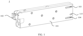
- FIG. 1 is a schematic diagram of an overall structure of a circuit breaker 1 according to an embodiment of this application.
- the circuit breaker 1 provided in this embodiment of this application may include a housing 101 and a button mechanism 102 disposed on the housing 101.
- the button mechanism 102 may be used as a switch of the circuit breaker 1, to manually switch the circuit breaker 1 between a closed state and an open state.
- the circuit breaker 1 further includes cable inlet ports disposed in the housing 101, and the cable inlet ports are configured to connect to a power supply line. There are two cable inlet ports: a first electrode cable inlet port 103 and a second electrode cable inlet port 104.
- the first electrode cable inlet port 103 is connected to a first electrode of a power supply and distribution system through a copper bar 105A
- the second electrode cable inlet port 104 is connected to a second electrode of the power supply and distribution system through a copper bar 105B
- the first electrode cable inlet port 103 and the second electrode cable inlet port 104 may be used as power supply line ports of an electrical device, so that the two cable inlet ports are connected to the power supply line.
- the circuit breaker 1 in this embodiment of this application further includes cable outlet ports.
- the first electrode cable outlet port 106 is used as a power receiving line port for connecting the circuit breaker 1 to the electrical device
- the second electrode cable outlet port 107 is used as another power receiving line port for connecting the circuit breaker 1 to the electrical device, so that the two cable outlet ports are connected to a power receiving line.
- the first electrode cable inlet port 103 may be electrically connected to the first electrode cable outlet port 106
- the second electrode cable inlet port 104 may be electrically connected to the second electrode cable outlet port 107.
- the first electrode cable outlet port 106 and the second electrode cable outlet port 107 may be disposed on a same side of the housing 101 as the button mechanism 102, to facilitate use of the circuit breaker 1.
- an on/off system may be disposed in the circuit breaker 1.
- a power supply on/off state of the electrical device can be controlled by controlling a connection/disconnection between the first electrode cable inlet port 103 and the first electrode cable outlet port 106 or by controlling a connection/disconnection between the second electrode cable inlet port 104 and the second electrode cable outlet port 107.
- a manner of connecting the second electrode cable inlet port 104 to the second electrode cable outlet port 107 may be but is not limited to a connection implemented through a copper bar 105C.
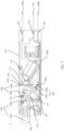
- the on/off system may include an operating mechanism 108 and a current collection mechanism 109.
- the operating mechanism 108 and the current collection mechanism 109 are disposed in the housing 101 of the circuit breaker 1.
- the operating mechanism 108 is rotatably connected to the button mechanism 102.
- the operating mechanism 108 includes a rotating part 1081 and a first moving contact 1082 disposed on the rotating part 1081.
- the first moving contact 1082 is electrically connected to the first electrode cable inlet port 103.
- the button mechanism 102 includes a button 1021 and a rotating shaft 1022.
- a first connecting rod 110 is disposed between the rotating shaft 1022 and the rotating part 1081 of the operating mechanism 108.
- One end of the first connecting rod 110 is fastened to the rotating shaft 1022, for example, fastened to an edge location of the rotating shaft 1022, so that the first connecting rod 110 is driven to rotate in a rotation process of the rotating shaft 1022.
- the other end of the first connecting rod 110 is fastened to the rotating part 1081, and may be specifically fastened to an edge location of the rotating part 1081, so that the first connecting rod 110 can drive the rotating part 1081 to rotate.
- the current collection mechanism 109 is provided with a first fixed contact 1091.
- the first fixed contact 1091 is disposed in a rotation direction of the rotating part 1081 and may be in contact with the first moving contact 1082, so that the current collection mechanism 109 can collect an electrical signal of the first electrode cable inlet port 103.
- a current collection mechanism 109 with high precision may be selected for specific disposing of the current collection mechanism 109.
- the on/off system may further include a second moving contact 1061 disposed between the first electrode cable outlet port 106 and the current collection mechanism 109.
- the current collection mechanism 109 is further provided with a second fixed contact 1092.
- the second fixed contact 1092 is electrically connected to the first fixed contact 1091.
- the second fixed contact 1092 may be in contact with the second moving contact 1061 to implement an electrical connection between the first electrode cable outlet port 106 and the current collection mechanism 109.
- the circuit breaker 1 may make the second fixed contact 1092 and the second moving contact 1061 in a contact state.
- the button 1021 of the button mechanism 102 when the button 1021 of the button mechanism 102 is pressed, the button 1021 moves towards an interior of the housing 101 of the circuit breaker 1, to push the rotating shaft 1022 to rotate.
- the first connecting rod 110 rotates with rotation of the rotating shaft 1022, to push the first moving contact 1082 on the rotating part 1081 of the operating mechanism 108 to rotate in a direction towards the first fixed contact 1091 of the current collection mechanism 109, until the first moving contact 1082 comes into contact with the first fixed contact 1091.
- a circuit between the first electrode cable outlet port 106 and the first electrode cable inlet port 103 is in a connected state.
- the circuit breaker 1 when the circuit breaker 1 is in a state shown in FIG.
- a rotation direction of the rotating shaft 1022 and a location at which the first connecting rod 110 is disposed between the rotating shaft 1022 and the rotating part 1081 may be further adjusted, so that when the button 1021 is pressed, the first moving contact 1082 rotates in the direction towards the first fixed contact 1091; and when the button 1021 is pulled out of the housing 101 of the circuit breaker 1, the first moving contact 1082 rotates in a direction away from the first fixed contact 1091.
- a second connecting rod 1023 may be disposed between the button 1021 and the rotating shaft 1022, one end of the second connecting rod 1023 is fastened to the button, and the other end of the second connecting rod 1023 is fastened to an edge location of the rotating shaft 1022.
- a specific location of the second connecting rod 1023 on the rotating shaft 1022 may be arranged based on a requirement on the rotation direction of the rotating shaft 1022.
- the second connecting rod 1023 is fixedly connected to a low location of the rotating shaft 1022. In this way, when the button 1021 of the button mechanism 102 is pressed, the rotating shaft 1022 may be controlled to rotate counterclockwise. In this case, the first connecting rod 110 rotates clockwise to drive the rotating part 1081 to rotate clockwise.
- a short circuit fault may occur in the power receiving line. If the power supply line still supplies electrical energy to the power receiving line after the fault occurs, a more serious accident may be caused, and consequently a major safety hazard exists.
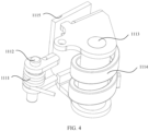
- a short-circuit protection mechanism 111 is disposed in the circuit breaker 1. The short-circuit protection mechanism 111 is disposed on one side of the operating mechanism 108. For specific disposing of the short-circuit protection mechanism 111, with reference to FIG.
- the short-circuit protection mechanism 111 includes an electromagnetic coil 1114, an iron core 1113, a shaft 1112, an armature spring 1111, and an armature 1115.
- the electromagnetic coil 1114 is sleeved on the iron core 1113
- the armature spring 1111 is sleeved on the shaft 1112
- the armature 1115 is fixedly connected to the armature spring 1111.
- one end of the electromagnetic coil 1114 is electrically connected to the second moving contact 1061 through a conductor (for example, a metal wire or a metal sheet), and the other end of the electromagnetic coil 1114 is electrically connected to the first electrode cable outlet port 106.
- the current flowing through the electromagnetic coil 1114 is excessively large.
- the electromagnetic coil 1114 generates a large magnetic field, to generate electromagnetic force that attracts the armature to rotate around the shaft.
- the armature 1115 pushes the rotating part 1081 of the operating mechanism 108 to rotate, so that the first moving contact 1082 moves in the direction away from the first fixed contact 1091, until the first moving contact 1082 is separated from the first fixed contact 1091. In this way, the current path between the first electrode cable inlet port 103 and the first electrode cable outlet port 106 is cut off, thereby implementing a short-circuit protection function.
- an overload protection mechanism 112 may be further disposed in the circuit breaker 1.
- the overload protection mechanism 112 may be disposed between the operating mechanism 108 and the first electrode cable inlet port 103. One end of the overload protection mechanism 112 may be electrically connected to the first electrode cable inlet port 103, and the other end of the overload protection mechanism 112 may be electrically connected to the first moving contact 1082.
- the overload protection mechanism 112 is made of a material that can bend and deform when subjected to heat.
- the overload protection mechanism 112 may be made of a shape memory alloy.
- the shape memory alloy is a material including more than two metal elements with a shape memory effect through thermoelastic martensitic phase transformation and their inverse transformation.
- the mechanical part made of the shape memory alloy can be embodied as follows: After plastic deformation occurs in the mechanical part within a specific temperature range, the mechanical part can be restored to its original shape within another temperature range.
- the overload protection mechanism 112 may be made of a bimetallic strip.
- a bimetallic strip is a composite material including two or more metals or other materials with suitable properties.
- the bimetallic strip is also referred to as a thermal bimetal strip. Due to different coefficients of thermal expansion of various layers, when a temperature changes, deformation of an active layer is greater than that of a passive layer, so that the entire bimetallic strip bends towards the passive layer.
- a third connecting rod 113 may be further disposed between the overload protection mechanism 112 and the operating mechanism 108, and a first sliding slot 1083 is further disposed on the rotating part 1081 of the operating mechanism 108.
- One end of the third connecting rod 113 is hinged to the overload protection mechanism 112, and the other end of the third connecting rod 113 is capable of sliding in the first sliding slot 1083.
- a connecting part 114 is further disposed on an inner sidewall of the housing 101 of the circuit breaker 1, the connecting part 114 is disposed on one side that is of the first moving contact 1082 and that is away from the first fixed contact 1091, and a second sliding slot 1141 is disposed on the connecting part 114.
- a hinge point at which the third connecting rod 113 is hinged to the overload protection mechanism 112 may slide along the second sliding slot 1141, and the overload protection mechanism 112 is rigidly connected to the first electrode cable inlet port 103. It can be understood that in this embodiment of this application, to prevent the third connecting rod 113 from falling out of the first sliding slot 1083 in a process in which the third connecting rod 113 slides along the first sliding slot 1083, a shape of one end that is of the third connecting rod 113 and that fits in with the first sliding slot 1083 may be arranged in a hook shape or the like.
- the third connecting rod 113 and the overload protection mechanism 112 may be disposed on two sides of the connecting part 114 without being limited thereto, and the hinged connection between the third connecting rod 113 and the overload protection mechanism 112 is implemented by using a hinge pin disposed through the second sliding slot 1141.
- the overload protection mechanism 112 deforms, so that the hinge point at which the third connecting rod 113 is hinged to the overload protection mechanism 112 slides along the second sliding slot 1141, to drive the third connecting rod 113 to move in a direction away from the operating mechanism 108.
- the third connecting rod 113 slides in the first sliding slot 1083 and pulls the rotating part 1081 to rotate, so that the first moving contact 1082 moves in the direction away from the first fixed contact 1091, until the first moving contact 1082 is separated from the first fixed contact 1091.
- the current path between the first electrode cable inlet port 103 and the first electrode cable outlet port 106 is cut off, thereby implementing an overload protection function.
- the foregoing disposing manner of the overload protection mechanism 112 is merely an example for description provided in this embodiment of this application. In other possible embodiments of this application, an overload protection mechanism 112 in another form may be alternatively used, and a working principle thereof is similar to that described above. Details are not described herein.
- the circuit breaker 1 further has a signal port 115 and a control apparatus.
- the signal port 115 may be disposed at one end of the housing 101 of the circuit breaker 1, and the control apparatus may be but is not limited to a signal circuit board 116, for example, may be a printed circuit board (printed circuit board, PCB).
- the signal circuit board 116 may be inserted into the signal port 115.
- a signal terminal 1151 is disposed in the signal port 115 (referring to FIG. 6 ).
- the signal terminal 1151 is connected to the signal circuit board 116 by using a signal.
- a notch 1161 is disposed at an end of the signal circuit board 116.
- a limiting structure 1152 may be disposed in the signal port 115.
- the limiting structure 1152 may be disposed as a protruding structure or a columnar structure, without being limited thereto.
- the limiting structure 1152 may be correspondingly inserted into the notch 1161 of the signal circuit board 116, to limit the signal terminal 1151 in the signal port 115 when the signal circuit board 116 is inserted into the signal port 115, so that the signal circuit board 116 is inserted into the signal terminal 1151 in place. This improves reliability of the connection between the signal terminal 1151 and the signal circuit board 116, and implements stable transmission of an electrical signal between the signal terminal 1151 and the signal circuit board 116.
- the limiting structure 1152 may be disposed at any location of the signal port 115.
- FIG. 6 there is one limiting structure 1152, and the limiting structure 1152 is disposed at a middle location of the signal port 115.
- FIG. 8 there are two limiting structures 1152, and the two limiting structures 1152 are disposed at two ends of the signal port 115.
- limiting structures 1152 there are two limiting structures 1152, the two limiting structures 1152 are biased at one end of the signal port 115, and a signal terminal 1151 is disposed between the two limiting structures 1152.
- a signal terminal 1151 is disposed between any two adjacent limiting structures 1152.
- the circuit breaker 1 in this embodiment of this application may further include a contactor mechanism 117.
- the signal circuit board 116 is electrically connected to the contactor mechanism 117 through the signal terminal, the contactor mechanism 117 is connected to the second moving contact 1061 through a push rod 118, the signal circuit board 116 can control an action of the contactor mechanism 117, and the push rod 118 moves with the contactor mechanism 117, to drive the second moving contact 1061 to move in a direction close to or away from the second fixed contact 1092.
- the circuit breaker 1 is in the state shown in FIG. 3 .
- Both the circuit between the first electrode cable outlet port 106 and the first electrode cable inlet port 103 and a circuit between the second electrode cable outlet port 107 and the second electrode cable inlet port 104 are in a connected state.
- the signal circuit board 116 may send a first action signal to the contactor mechanism 117.
- the contactor mechanism 117 drives the push rod 118 to move in a direction away from the current collection mechanism 109, so that the second moving contact 1061 is disconnected from the second fixed contact 1092 and a state shown in FIG. 11 is presented.
- the current path between the first electrode cable outlet port 106 and the first electrode cable inlet port 103 is cut off.
- the signal circuit board 116 may send a second action signal to the contactor mechanism 117.
- the contactor mechanism 117 drives the push rod 118 to move in a direction close to the current collection mechanism 109, so that the second moving contact 1061 is connected to the second fixed contact 1092 and the state shown in FIG. 3 is presented.
- the contactor mechanism 117 and the signal circuit board 116 are disposed in the circuit breaker 1 in this embodiment of this application, to implement remote control on on/off state switching between the power receiving line and the power supply line.
- the circuit breaker 1 is applied to a radio base station disposed at a remote location, or is applied to a scenario in which periodic power-on or power-off is needed or opening or closing is performed according to system instructions, for example, a scenario in which a smart meter remotely performs power-off for a user who is in arrears with an electricity fee.
- a worker can implement switching between the closed state and the open state of the circuit breaker 1 through remote control by the signal circuit board 116 on the contactor mechanism 117, without a need to close or open the circuit breaker 1 on site.
- circuit breaker 1 when used for electrical devices (for example, 4G base stations or 5G gNBs in a remote area) that have a low demand or have no demand in a specific time period, the circuit breaker 1 can be switched between the closed state and the open state in time, and this is conducive to energy conservation.
- electrical devices for example, 4G base stations or 5G gNBs in a remote area
- the signal circuit board 116 is further electrically connected to the first fixed contact 1091 and the second fixed contact 1092 of the current collection mechanism 109, to detect an on/off state of the circuit breaker 1 by detecting current intensity of the first fixed contact 1091 and the second fixed contact 1092.
- the current intensity at the first fixed contact 1091 detected by the signal circuit board 116 falls within a current intensity threshold range that is in a circuit connected state and that is preset for the circuit breaker 1
- the current intensity at the second fixed contact 1092 detected by the signal circuit board 116 exceeds a current intensity threshold that is in the circuit connected state and that is preset for the circuit breaker 1.
- the signal circuit board 116 only needs to control the contactor mechanism 117.
- the signal circuit board 116 detects that the first moving contact 1082 is disconnected from the first fixed contact 1091 and the second moving contact 1061 is also disconnected from the second fixed contact 1092. In this case, if the power receiving line needs to be connected to the power supply line, the worker needs to press the button 1021 of the circuit breaker 1 on site; and then the signal circuit board 116 controls the contactor mechanism 117, so that the second moving contact 1061 is connected to the second fixed contact 1092. Certainly, alternatively, the signal circuit board 116 may first control the contactor mechanism 117, so that the second moving contact 1061 is connected to the second fixed contact 1092; and then the button 1021 of the circuit breaker 1 is pressed.
- remote fault detection may be performed by the signal circuit board 116 on the circuit breaker 1. This can effectively reduce difficulty in troubleshooting a fault of the circuit breaker 1, and reduce work intensity of the worker and maintenance costs. For an electrical device disposed at a remote location, advantages of the circuit breaker 1 in this embodiment of this application are more significant.
- an arc extinguishing mechanism 119 may be further disposed in the circuit breaker 1.
- the arc extinguishing mechanism 119 can effectively extinguish electric arcs generated between the first moving contact 1082 and the first fixed contact 1091 and between the second moving contact 1061 and the second fixed contact 1092. This improves safety of using the circuit breaker 1.
- the arc extinguishing mechanism 119 may be disposed at any location provided that the arc extinguishing mechanism 119 is disposed close to the first moving contact 1082, the first fixed contact 1091, the second moving contact 1061, and the second fixed contact 1092, to achieve a desirable arc extinguishing effect.
- the arc extinguishing mechanism 119 may be provided between the operating mechanism 108 and the contactor mechanism 117.
- the first fixed contact 1091 and the second fixed contact 1092 of the current collection mechanism 109 may be electrically connected to the arc extinguishing mechanism 119 through a copper bar 105D, and the arc extinguishing mechanism 119 is electrically connected to the signal terminal in the signal port 115 of the circuit breaker 1.
- the operating mechanism 108 and the contactor mechanism 117 can share one arc extinguishing system, thereby improving the safety of using the circuit breaker 1.
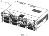
- an embodiment of this application further provides a power distribution box.
- the power distribution box is configured to implement circuit deployment and distribution.
- the power distribution box can be applied to a power supply and distribution system of a wireless high-power 5G (fifth generation mobile communications technology, 5G for short) gNB, and can also be applied to a power supply and distribution system of a household circuit.
- An application field of the power distribution box is not limited in this embodiment, and the power distribution box can be applied to line connections in any field.
- the power distribution box 2 in this embodiment of this application may include a box body 201 and one or more foregoing circuit breakers 1 inserted into the box body 201.
- the plurality of circuit breakers 1 are disposed in parallel, and each circuit breaker 1 is connected to a power supply end of a power supply and distribution system.
- the power supply end may be a mains supply, a generator, a battery, or the like.
- the circuit breaker 1 may divide one line of electricity entering the power distribution box 2 into a plurality of lines of electricity, and each circuit breaker 1 may be connected to one electrical device or may be connected to a plurality of electrical devices.
- each circuit breaker 1 may be connected to one electrical device or may be connected to a plurality of electrical devices.
- one circuit breaker 1 may be connected to an air conditioner
- another circuit breaker 1 may be connected to a refrigerator
- another circuit breaker 1 may be connected to a lighting device.
- the circuit breaker 1 divides one line of electricity entering the power distribution box into a plurality of lines of electricity, which are used to respectively supply power to different electrical devices. In this way, even if a fault occurs in one circuit, electrical devices in other circuits can still continue to work, thereby implementing a circuit protection function.
- a working state of the circuit breaker 1 can be remotely monitored, and closing/opening of the circuit breaker 1 can be remotely controlled, thereby effectively reducing maintenance costs of the circuit breaker 1.
Landscapes
- Engineering & Computer Science (AREA)
- Architecture (AREA)
- Civil Engineering (AREA)
- Structural Engineering (AREA)
- Breakers (AREA)
- Distribution Board (AREA)
Claims (11)
- Schutzschalter (1), der ein Gehäuse (101), einen Stromsignalerfassungsmechanismus (109), einen Betriebsmechanismus (108), einen Schützmechanismus (117), Kabeleingangsanschlüsse (103, 104), Kabelausgangsanschlüsse (106, 107) und eine Steuervorrichtung (116) umfasst, wobei der Stromsignalerfassungsmechanismus (109), der Betriebsmechanismus (108) und der Schützmechanismus (117) in dem Gehäuse (101) angeordnet sind;der Stromsignalerfassungsmechanismus (109) einen ersten festen Kontakt (1091) und einen zweiten festen Kontakt (1092) umfasst und der erste feste Kontakt (1091) mit dem zweiten festen Kontakt (1092) elektrisch verbunden ist;die Kabeleingangsanschlüsse (103, 104) mit einer Stromversorgungsleitung verbindbar sind und einen ersten Elektrodenkabeleingangsanschluss (103) und einen zweiten Elektrodenkabeleingangsanschluss (104) umfassen,der Betriebsmechanismus (108) einen sich drehenden Teil (1081) und einen ersten Bewegungskontakt (1082) aufweist, der erste Bewegungskontakt (1082) mit dem ersten Elektrodenkabeleingangsanschluss (103) elektrisch verbunden ist und der sich drehende Teil (1081) in der Lage ist, den ersten Bewegungskontakt (1082) anzusteuern, sodass er sich dreht, um eine Schaltung zwischen dem ersten Bewegungskontakt (1082) und dem ersten festen Kontakt (1091) verbunden oder getrennt zu machen;die Kabelausgangsanschlüsse (106, 107) mit einer Stromaufnahmeleitung verbindbar sind und einen ersten Elektrodenkabelausgangsanschluss (106) und einen zweiten Elektrodenkabelausgangsanschluss (107) umfassen, wobei der erste Elektrodenkabelausgangsanschluss (106) mit einem zweiten Bewegungskontakt (1061) elektrisch verbunden ist und der zweite Elektrodenkabelausgangsanschluss (107) mit dem zweiten Elektrodenkabeleingangsanschluss (104) elektrisch verbunden ist; unddie Steuervorrichtung (116) zum Steuern des Schützmechanismus (117) zum Ansteuern des zweiten Bewegungskontakts (1061), sodass er sich bewegt, um eine Schaltung zwischen dem zweiten Bewegungskontakt (1061) und dem zweiten festen Kontakt (1092) verbunden oder getrennt zu machen, ausgelegt ist;wobei der Schutzschalter (1) ferner einen Kurzschlussschutzmechanismus (111) umfasst, der Kurzschlussschutzmechanismus (111) an einer Seite des Betriebsmechanismus (108) angeordnet ist, der Kurzschlussschutzmechanismus (111) eine elektromagnetische Spule (1114), einen Eisenkern (1113), eine Welle (1112), eine Ankerfeder (1111) und einen Anker (1115) umfasst, die elektromagnetische Spule (1114) auf den Eisenkern (1113) geschoben ist, die Ankerfeder (1111) auf die Welle (1112) geschoben ist und der Anker (1115) mit der Ankerfeder (1111) fest verbunden ist und ein Ende der elektromagnetischen Spule (1114) mit dem zweiten Bewegungskontakt (1061) durch einen Leiter elektrisch verbunden ist und das andere Ende der elektromagnetischen Spule (1114) mit dem ersten Elektrodenkabelausgangsanschluss (106) elektrisch verbunden ist; undwenn ein Strom, der durch die elektromagnetische Spule (1114) fließt, einen voreingestellten Stromschwellenbereich überschreitet, elektromagnetische Kraft, die durch die elektromagnetische Spule (1114) erzeugt wird, den Anker (1115) anzieht, sodass er sich um die Welle (1112) dreht, und der Anker (1115) den sich drehenden Teil (1081) drückt, sodass er sich dreht, sodass die Schaltung zwischen dem ersten Bewegungskontakt (1082) und dem ersten festen Kontakt (1091) getrennt wird.
- Schutzschalter (1) nach Anspruch 1, wobei der Schutzschalter (1) ferner einen Signalanschluss (115) umfasst und eine Signalklemme (1151) in dem Signalanschluss (115) angeordnet ist und
die Steuervorrichtung (116) eine Signalleiterplatte ist, die Signalleiterplatte (116) in den Signalanschluss (115) eingeführt ist und die Signalklemme (1151) mit der Signalleiterplatte (116) durch Verwenden eines Signals verbunden ist. - Schutzschalter (1) nach Anspruch 2, wobei eine Grenzstruktur (1152) in dem Signalanschluss (115) angeordnet ist, eine Kerbe (1161) an einem Ende der Signalleiterplatte (116) angeordnet ist und die Grenzstruktur (1152) in die Kerbe (1161) eingeführt ist.
- Schutzschalter (1) nach einem der Ansprüche 1 bis 3, wobei der Schutzschalter (1) ferner einen Überlastschutzmechanismus (112) umfasst und der Überlastschutzmechanismus (112) aus einem Material besteht, das bieg- und verformbar ist, wenn es Wärme ausgesetzt ist; und ein Ende des Überlastschutzmechanismus (112) mit dem ersten Elektrodenkabeleingangsanschluss (103) starr verbunden ist; und
wenn Wärme, die in der Stromaufnahmeleitung erzeugt wird, einen voreingestellten Wärmeschwellenbereich überschreitet, sich der Überlastschutzmechanismus (112) verformt und den sich drehenden Teil (1081) des Betriebsmechanismus (108) ansteuert, sodass er sich dreht, sodass die Schaltung zwischen dem ersten Bewegungskontakt (1082) und dem ersten festen Kontakt (1091) getrennt wird. - Schutzschalter (1) nach Anspruch 4, wobei ein erster Gleitschlitz (1083) an dem sich drehenden Teil (1081) des Betriebsmechanismus (108) angeordnet ist und eine dritte Verbindungsstange (113) zwischen dem Überlastschutzmechanismus (112) und dem Betriebsmechanismus (108) angeordnet ist und ein Ende der dritten Verbindungsstange (113) an den Überlastschutzmechanismus (112) angelenkt ist und das andere Ende der dritten Verbindungsstange (113) in der Lage ist, entlang des ersten Gleitschlitzes (1083) zu gleiten.
- Schutzschalter (1) nach Anspruch 5, wobei ein Verbindungsteil (114) an einer inneren Seitenwand des Gehäuses (101) angeordnet ist, ein zweiter Gleitschlitz (1141) an dem Verbindungsteil (114) angeordnet ist und ein Gelenkpunkt zwischen der dritten Verbindungsstange (113) und dem Überlastschutzmechanismus (112) in der Lage ist, entlang des zweiten Gleitschlitzes (1141) zu gleiten.
- Schutzschalter (1) nach einem der Ansprüche 1 bis 6, wobei der Schutzschalter (1) ferner einen Tastenmechanismus (102) umfasst und eine Bewegung des Tastenmechanismus in der Lage ist, den sich drehenden Teil (1081) des Betriebsmechanismus (108) anzusteuern, sodass er sich dreht, um die Schaltung zwischen dem ersten festen Kontakt (1091) und dem ersten Bewegungskontakt (1082) verbunden oder getrennt zu machen;wobei der Tastenmechanismus eine Taste (1021), eine sich drehende Welle (1022) und eine erste Verbindungsstange (110) umfasst, ein Ende der ersten Verbindungsstange (110) an einer Kante der sich drehenden Welle (1022) befestigt ist und das andere Ende der ersten Verbindungsstange (110) an einer Kante des sich drehenden Teils (1081) des Betriebsmechanismus (108) befestigt ist; undwenn sich die Taste (1021) in Richtung einer Innenseite des Gehäuses (101) bewegt, eine Drehung der sich drehenden Welle (1022) die erste Verbindungsstange (110) ansteuert, sodass sie sich dreht, und der sich drehende Teil (1081) sich mit der ersten Verbindungsstange (110) dreht, um die Schaltung zwischen dem ersten festen Kontakt (1091) und dem ersten Bewegungskontakt (1082) verbunden zu machen; oder wenn sich die Taste (1021) in Richtung einer Außenseite des Gehäuses (101) bewegt, eine Drehung der sich drehenden Welle (1022) die erste Verbindungsstange (110) ansteuert, sodass sie sich dreht, und der sich drehende Teil (1081) sich mit der ersten Verbindungsstange (110) dreht, um die Schaltung zwischen dem ersten festen Kontakt (1091) und dem ersten Bewegungskontakt (1082) getrennt zu machen.
- Schutzschalter (1) nach einem der Ansprüche 1 bis 7, wobei der Schützmechanismus (117) mit dem zweiten Bewegungskontakt (1061) durch eine Schubstange (118) verbunden ist.
- Schutzschalter (1) nach einem der Ansprüche 1 bis 8, wobei der Schutzschalter (1) ferner einen Lichtbogenlöschmechanismus (119) umfasst und der erste feste Kontakt (1091) und der zweite feste Kontakt (1092) des Stromsignalerfassungsmechanismus (109) mit dem Lichtbogenlöschmechanismus (119) elektrisch verbunden sind und wenn der Schutzschalter (1) ferner den Signalanschluss (115) umfasst und die Signalklemme (1151) in dem Signalanschluss (115) angeordnet ist, der Lichtbogenlöschmechanismus (119) mit der Signalklemme (1151) elektrisch verbunden ist.
- Stromverteilungskasten (2), der in einem Stromversorgungs- und -verteilungssystem verwendet wird und einen Gehäusekörper (201) und den Schutzschalter (1) nach einem der Ansprüche 1 bis 9 umfasst, wobei der Schutzschalter (1) in den Gehäusekörper (201) eingeführt ist und der Schutzschalter (1) mit einem Stromversorgungsende des Stromversorgungs- und -verteilungssystems elektrisch verbunden ist.
- Stromverteilungskasten (2) nach Anspruch 10, wobei eine Vielzahl von Schutzschaltern (1) vorhanden ist und die Vielzahl von Schutzschaltern (1) parallel angeordnet sind und jeder Schutzschalter (1) mit einem elektrischen Gerät elektrisch verbunden ist oder jeder Schutzschalter (1) mit einer Vielzahl von elektrischen Geräten elektrisch verbunden ist.
Applications Claiming Priority (1)
| Application Number | Priority Date | Filing Date | Title |
|---|---|---|---|
| PCT/CN2020/089267 WO2021223242A1 (zh) | 2020-05-08 | 2020-05-08 | 一种断路器及配电盒 |
Publications (3)
| Publication Number | Publication Date |
|---|---|
| EP4138110A1 EP4138110A1 (de) | 2023-02-22 |
| EP4138110A4 EP4138110A4 (de) | 2023-05-24 |
| EP4138110B1 true EP4138110B1 (de) | 2024-07-31 |
Family
ID=78468622
Family Applications (1)
| Application Number | Title | Priority Date | Filing Date |
|---|---|---|---|
| EP20934567.7A Active EP4138110B1 (de) | 2020-05-08 | 2020-05-08 | Schutzschalter und stromverteilungskasten |
Country Status (4)
| Country | Link |
|---|---|
| US (1) | US12308191B2 (de) |
| EP (1) | EP4138110B1 (de) |
| CN (1) | CN113924632A (de) |
| WO (1) | WO2021223242A1 (de) |
Families Citing this family (5)
| Publication number | Priority date | Publication date | Assignee | Title |
|---|---|---|---|---|
| CN112952564B (zh) * | 2019-12-25 | 2022-04-22 | 华为数字能源技术有限公司 | 配电模块及通信电源系统 |
| CN114698295B (zh) * | 2022-03-16 | 2023-10-03 | 国网山东省电力公司惠民县供电公司 | 一种电力仿真信号转换装置 |
| CN117524799B (zh) * | 2023-11-11 | 2024-07-19 | 悦动智能电器有限公司 | 一种内置式断路器及电能表 |
| CN118116777B (zh) * | 2024-03-05 | 2024-09-03 | 浙江东亚电子有限公司 | 一种紧凑型高密度智能断路器 |
| CN121171841A (zh) * | 2024-06-19 | 2025-12-19 | 上海正泰智能科技有限公司 | 断路器 |
Family Cites Families (14)
| Publication number | Priority date | Publication date | Assignee | Title |
|---|---|---|---|---|
| GB2246909B (en) * | 1990-07-16 | 1995-02-22 | Terasaki Denki Sangyo Kk | Circuit breaker including forced contact parting mechanism capable of self-retaining under short circuit condition |
| JPH08124474A (ja) * | 1994-10-26 | 1996-05-17 | Matsushita Electric Works Ltd | 回路遮断器 |
| DE69627973T2 (de) * | 1995-12-20 | 2003-11-27 | Legrand Snc, Limoges | Hilfsschalter für Ausschalter und entsprechender Ausschalter |
| CN100477055C (zh) * | 2005-09-19 | 2009-04-08 | 上海电器科学研究所(集团)有限公司 | 选择性保护开关 |
| CN104701111B (zh) * | 2015-03-19 | 2017-03-22 | 河北宝凯电气股份有限公司 | 一种可快速分断的小型断路器 |
| CN205016477U (zh) | 2015-07-16 | 2016-02-03 | 上海良信电器股份有限公司 | 一种插入式小型断路器壳体安装结构 |
| CN206774470U (zh) | 2017-04-24 | 2017-12-19 | 深圳曼顿科技有限公司 | 带数据检测功能的新型低压断路器 |
| CN106971923B (zh) * | 2017-04-28 | 2018-09-18 | 首瑞(天津)电气设备有限公司 | 一种受信息控制的断路器 |
| KR20190028171A (ko) * | 2017-09-08 | 2019-03-18 | (주)토즈테크 | 저항성 누설전류검출모듈을 갖는 분전함 |
| KR102082688B1 (ko) * | 2017-09-08 | 2020-04-23 | (주)토즈테크 | 부스바 일체형 계량기를 갖는 분전함 |
| CN108321047B (zh) | 2018-02-02 | 2024-07-05 | 深圳曼顿科技有限公司 | 具有零序互感器安装结构的小型断路器 |
| CN109686625B (zh) * | 2018-12-28 | 2024-05-07 | 浙江正泰电器股份有限公司 | 小型断路器 |
| CN110137048A (zh) * | 2019-05-30 | 2019-08-16 | 天津市中力神盾电子科技有限公司 | 一种智能断路器 |
| US11728112B2 (en) * | 2020-11-30 | 2023-08-15 | Xiamen Hongfa Electrical Safety & Controls Co., Ltd. | Double-pole circuit breaker and distribution box |
-
2020
- 2020-05-08 EP EP20934567.7A patent/EP4138110B1/de active Active
- 2020-05-08 WO PCT/CN2020/089267 patent/WO2021223242A1/zh not_active Ceased
- 2020-05-08 CN CN202080029502.0A patent/CN113924632A/zh active Pending
-
2022
- 2022-11-04 US US17/981,215 patent/US12308191B2/en active Active
Also Published As
| Publication number | Publication date |
|---|---|
| WO2021223242A1 (zh) | 2021-11-11 |
| US12308191B2 (en) | 2025-05-20 |
| CN113924632A (zh) | 2022-01-11 |
| EP4138110A1 (de) | 2023-02-22 |
| EP4138110A4 (de) | 2023-05-24 |
| US20230054526A1 (en) | 2023-02-23 |
Similar Documents
| Publication | Publication Date | Title |
|---|---|---|
| EP4138110B1 (de) | Schutzschalter und stromverteilungskasten | |
| CA2342484C (en) | Method and apparatus for supplying power to a load circuit from alternate electric power sources | |
| CN113035661B (zh) | 漏电断路器 | |
| JPS61121231A (ja) | 遮断器 | |
| CN106710980B (zh) | 一种微型断路器 | |
| CN212783318U (zh) | 断路器 | |
| CN113889377A (zh) | 断路器 | |
| CN209859890U (zh) | 断路器的跳闸机构 | |
| CN210120060U (zh) | 具有无线通信的电能表外置断路器结构 | |
| CN209249406U (zh) | 一种重合闸剩余电流保护断路器 | |
| US20220352713A1 (en) | Reverse power connection preventing circuit, power distribution apparatus, and power supply and distribution system | |
| CN104078288B (zh) | 一种电磁操作机构 | |
| EP2080209B1 (de) | Kontaktarm und armaturenplatte für ein beleuchtungssteuerungsmodul | |
| KR101168257B1 (ko) | 전자석 엑츄레이터를 탑재한 전자식 배선용 차단기 | |
| CN211405921U (zh) | 一种电厂电动机控制装置 | |
| CN112735924A (zh) | 一种智能断路器 | |
| CN109243929B (zh) | 一种带有可调型过载报警不脱扣功能的塑壳断路器 | |
| CN203553078U (zh) | 数模化电子式微型断路器 | |
| CN218677003U (zh) | 断路器、供电装置及配电设备 | |
| CN113257639A (zh) | 一种断路器和配电盒 | |
| CN111430196A (zh) | 一种复合型开关 | |
| KR100521502B1 (ko) | 래치형 자동복귀 전자식 누전차단기 | |
| CN221327630U (zh) | 一种具有热电磁保护功能的塑壳断路器 | |
| CN222966034U (zh) | 一种电磁锁定的塑壳断路器 | |
| CN112701013A (zh) | 一种开关装置 |
Legal Events
| Date | Code | Title | Description |
|---|---|---|---|
| STAA | Information on the status of an ep patent application or granted ep patent |
Free format text: STATUS: THE INTERNATIONAL PUBLICATION HAS BEEN MADE |
|
| PUAI | Public reference made under article 153(3) epc to a published international application that has entered the european phase |
Free format text: ORIGINAL CODE: 0009012 |
|
| STAA | Information on the status of an ep patent application or granted ep patent |
Free format text: STATUS: REQUEST FOR EXAMINATION WAS MADE |
|
| 17P | Request for examination filed |
Effective date: 20221118 |
|
| AK | Designated contracting states |
Kind code of ref document: A1 Designated state(s): AL AT BE BG CH CY CZ DE DK EE ES FI FR GB GR HR HU IE IS IT LI LT LU LV MC MK MT NL NO PL PT RO RS SE SI SK SM TR |
|
| A4 | Supplementary search report drawn up and despatched |
Effective date: 20230424 |
|
| RIC1 | Information provided on ipc code assigned before grant |
Ipc: H01H 71/12 20060101AFI20230418BHEP |
|
| DAV | Request for validation of the european patent (deleted) | ||
| DAX | Request for extension of the european patent (deleted) | ||
| GRAP | Despatch of communication of intention to grant a patent |
Free format text: ORIGINAL CODE: EPIDOSNIGR1 |
|
| STAA | Information on the status of an ep patent application or granted ep patent |
Free format text: STATUS: GRANT OF PATENT IS INTENDED |
|
| INTG | Intention to grant announced |
Effective date: 20240328 |
|
| GRAS | Grant fee paid |
Free format text: ORIGINAL CODE: EPIDOSNIGR3 |
|
| GRAA | (expected) grant |
Free format text: ORIGINAL CODE: 0009210 |
|
| STAA | Information on the status of an ep patent application or granted ep patent |
Free format text: STATUS: THE PATENT HAS BEEN GRANTED |
|
| AK | Designated contracting states |
Kind code of ref document: B1 Designated state(s): AL AT BE BG CH CY CZ DE DK EE ES FI FR GB GR HR HU IE IS IT LI LT LU LV MC MK MT NL NO PL PT RO RS SE SI SK SM TR |
|
| P01 | Opt-out of the competence of the unified patent court (upc) registered |
Free format text: CASE NUMBER: APP_37036/2024 Effective date: 20240620 |
|
| REG | Reference to a national code |
Ref country code: CH Ref legal event code: EP Ref country code: GB Ref legal event code: FG4D |
|
| REG | Reference to a national code |
Ref country code: DE Ref legal event code: R096 Ref document number: 602020035108 Country of ref document: DE |
|
| REG | Reference to a national code |
Ref country code: IE Ref legal event code: FG4D |
|
| REG | Reference to a national code |
Ref country code: LT Ref legal event code: MG9D |
|
| REG | Reference to a national code |
Ref country code: NL Ref legal event code: MP Effective date: 20240731 |
|
| PG25 | Lapsed in a contracting state [announced via postgrant information from national office to epo] |
Ref country code: PT Free format text: LAPSE BECAUSE OF FAILURE TO SUBMIT A TRANSLATION OF THE DESCRIPTION OR TO PAY THE FEE WITHIN THE PRESCRIBED TIME-LIMIT Effective date: 20241202 |
|
| REG | Reference to a national code |
Ref country code: AT Ref legal event code: MK05 Ref document number: 1709302 Country of ref document: AT Kind code of ref document: T Effective date: 20240731 |
|
| PG25 | Lapsed in a contracting state [announced via postgrant information from national office to epo] |
Ref country code: PT Free format text: LAPSE BECAUSE OF FAILURE TO SUBMIT A TRANSLATION OF THE DESCRIPTION OR TO PAY THE FEE WITHIN THE PRESCRIBED TIME-LIMIT Effective date: 20241202 |
|
| PG25 | Lapsed in a contracting state [announced via postgrant information from national office to epo] |
Ref country code: NO Free format text: LAPSE BECAUSE OF FAILURE TO SUBMIT A TRANSLATION OF THE DESCRIPTION OR TO PAY THE FEE WITHIN THE PRESCRIBED TIME-LIMIT Effective date: 20241031 |
|
| PG25 | Lapsed in a contracting state [announced via postgrant information from national office to epo] |
Ref country code: FI Free format text: LAPSE BECAUSE OF FAILURE TO SUBMIT A TRANSLATION OF THE DESCRIPTION OR TO PAY THE FEE WITHIN THE PRESCRIBED TIME-LIMIT Effective date: 20240731 Ref country code: NL Free format text: LAPSE BECAUSE OF FAILURE TO SUBMIT A TRANSLATION OF THE DESCRIPTION OR TO PAY THE FEE WITHIN THE PRESCRIBED TIME-LIMIT Effective date: 20240731 Ref country code: PL Free format text: LAPSE BECAUSE OF FAILURE TO SUBMIT A TRANSLATION OF THE DESCRIPTION OR TO PAY THE FEE WITHIN THE PRESCRIBED TIME-LIMIT Effective date: 20240731 Ref country code: GR Free format text: LAPSE BECAUSE OF FAILURE TO SUBMIT A TRANSLATION OF THE DESCRIPTION OR TO PAY THE FEE WITHIN THE PRESCRIBED TIME-LIMIT Effective date: 20241101 |
|
| PG25 | Lapsed in a contracting state [announced via postgrant information from national office to epo] |
Ref country code: BG Free format text: LAPSE BECAUSE OF FAILURE TO SUBMIT A TRANSLATION OF THE DESCRIPTION OR TO PAY THE FEE WITHIN THE PRESCRIBED TIME-LIMIT Effective date: 20240731 |
|
| PG25 | Lapsed in a contracting state [announced via postgrant information from national office to epo] |
Ref country code: LV Free format text: LAPSE BECAUSE OF FAILURE TO SUBMIT A TRANSLATION OF THE DESCRIPTION OR TO PAY THE FEE WITHIN THE PRESCRIBED TIME-LIMIT Effective date: 20240731 |
|
| PG25 | Lapsed in a contracting state [announced via postgrant information from national office to epo] |
Ref country code: IS Free format text: LAPSE BECAUSE OF FAILURE TO SUBMIT A TRANSLATION OF THE DESCRIPTION OR TO PAY THE FEE WITHIN THE PRESCRIBED TIME-LIMIT Effective date: 20241130 Ref country code: AT Free format text: LAPSE BECAUSE OF FAILURE TO SUBMIT A TRANSLATION OF THE DESCRIPTION OR TO PAY THE FEE WITHIN THE PRESCRIBED TIME-LIMIT Effective date: 20240731 |
|
| PG25 | Lapsed in a contracting state [announced via postgrant information from national office to epo] |
Ref country code: HR Free format text: LAPSE BECAUSE OF FAILURE TO SUBMIT A TRANSLATION OF THE DESCRIPTION OR TO PAY THE FEE WITHIN THE PRESCRIBED TIME-LIMIT Effective date: 20240731 |
|
| PG25 | Lapsed in a contracting state [announced via postgrant information from national office to epo] |
Ref country code: ES Free format text: LAPSE BECAUSE OF FAILURE TO SUBMIT A TRANSLATION OF THE DESCRIPTION OR TO PAY THE FEE WITHIN THE PRESCRIBED TIME-LIMIT Effective date: 20240731 Ref country code: RS Free format text: LAPSE BECAUSE OF FAILURE TO SUBMIT A TRANSLATION OF THE DESCRIPTION OR TO PAY THE FEE WITHIN THE PRESCRIBED TIME-LIMIT Effective date: 20241031 |
|
| PG25 | Lapsed in a contracting state [announced via postgrant information from national office to epo] |
Ref country code: RS Free format text: LAPSE BECAUSE OF FAILURE TO SUBMIT A TRANSLATION OF THE DESCRIPTION OR TO PAY THE FEE WITHIN THE PRESCRIBED TIME-LIMIT Effective date: 20241031 Ref country code: PL Free format text: LAPSE BECAUSE OF FAILURE TO SUBMIT A TRANSLATION OF THE DESCRIPTION OR TO PAY THE FEE WITHIN THE PRESCRIBED TIME-LIMIT Effective date: 20240731 Ref country code: NO Free format text: LAPSE BECAUSE OF FAILURE TO SUBMIT A TRANSLATION OF THE DESCRIPTION OR TO PAY THE FEE WITHIN THE PRESCRIBED TIME-LIMIT Effective date: 20241031 Ref country code: NL Free format text: LAPSE BECAUSE OF FAILURE TO SUBMIT A TRANSLATION OF THE DESCRIPTION OR TO PAY THE FEE WITHIN THE PRESCRIBED TIME-LIMIT Effective date: 20240731 Ref country code: LV Free format text: LAPSE BECAUSE OF FAILURE TO SUBMIT A TRANSLATION OF THE DESCRIPTION OR TO PAY THE FEE WITHIN THE PRESCRIBED TIME-LIMIT Effective date: 20240731 Ref country code: IS Free format text: LAPSE BECAUSE OF FAILURE TO SUBMIT A TRANSLATION OF THE DESCRIPTION OR TO PAY THE FEE WITHIN THE PRESCRIBED TIME-LIMIT Effective date: 20241130 Ref country code: HR Free format text: LAPSE BECAUSE OF FAILURE TO SUBMIT A TRANSLATION OF THE DESCRIPTION OR TO PAY THE FEE WITHIN THE PRESCRIBED TIME-LIMIT Effective date: 20240731 Ref country code: GR Free format text: LAPSE BECAUSE OF FAILURE TO SUBMIT A TRANSLATION OF THE DESCRIPTION OR TO PAY THE FEE WITHIN THE PRESCRIBED TIME-LIMIT Effective date: 20241101 Ref country code: FI Free format text: LAPSE BECAUSE OF FAILURE TO SUBMIT A TRANSLATION OF THE DESCRIPTION OR TO PAY THE FEE WITHIN THE PRESCRIBED TIME-LIMIT Effective date: 20240731 Ref country code: ES Free format text: LAPSE BECAUSE OF FAILURE TO SUBMIT A TRANSLATION OF THE DESCRIPTION OR TO PAY THE FEE WITHIN THE PRESCRIBED TIME-LIMIT Effective date: 20240731 Ref country code: BG Free format text: LAPSE BECAUSE OF FAILURE TO SUBMIT A TRANSLATION OF THE DESCRIPTION OR TO PAY THE FEE WITHIN THE PRESCRIBED TIME-LIMIT Effective date: 20240731 Ref country code: AT Free format text: LAPSE BECAUSE OF FAILURE TO SUBMIT A TRANSLATION OF THE DESCRIPTION OR TO PAY THE FEE WITHIN THE PRESCRIBED TIME-LIMIT Effective date: 20240731 |
|
| PG25 | Lapsed in a contracting state [announced via postgrant information from national office to epo] |
Ref country code: DK Free format text: LAPSE BECAUSE OF FAILURE TO SUBMIT A TRANSLATION OF THE DESCRIPTION OR TO PAY THE FEE WITHIN THE PRESCRIBED TIME-LIMIT Effective date: 20240731 Ref country code: SM Free format text: LAPSE BECAUSE OF FAILURE TO SUBMIT A TRANSLATION OF THE DESCRIPTION OR TO PAY THE FEE WITHIN THE PRESCRIBED TIME-LIMIT Effective date: 20240731 Ref country code: RO Free format text: LAPSE BECAUSE OF FAILURE TO SUBMIT A TRANSLATION OF THE DESCRIPTION OR TO PAY THE FEE WITHIN THE PRESCRIBED TIME-LIMIT Effective date: 20240731 |
|
| PG25 | Lapsed in a contracting state [announced via postgrant information from national office to epo] |
Ref country code: EE Free format text: LAPSE BECAUSE OF FAILURE TO SUBMIT A TRANSLATION OF THE DESCRIPTION OR TO PAY THE FEE WITHIN THE PRESCRIBED TIME-LIMIT Effective date: 20240731 |
|
| PG25 | Lapsed in a contracting state [announced via postgrant information from national office to epo] |
Ref country code: CZ Free format text: LAPSE BECAUSE OF FAILURE TO SUBMIT A TRANSLATION OF THE DESCRIPTION OR TO PAY THE FEE WITHIN THE PRESCRIBED TIME-LIMIT Effective date: 20240731 |
|
| PG25 | Lapsed in a contracting state [announced via postgrant information from national office to epo] |
Ref country code: SK Free format text: LAPSE BECAUSE OF FAILURE TO SUBMIT A TRANSLATION OF THE DESCRIPTION OR TO PAY THE FEE WITHIN THE PRESCRIBED TIME-LIMIT Effective date: 20240731 Ref country code: IT Free format text: LAPSE BECAUSE OF FAILURE TO SUBMIT A TRANSLATION OF THE DESCRIPTION OR TO PAY THE FEE WITHIN THE PRESCRIBED TIME-LIMIT Effective date: 20240731 |
|
| REG | Reference to a national code |
Ref country code: DE Ref legal event code: R097 Ref document number: 602020035108 Country of ref document: DE |
|
| PLBE | No opposition filed within time limit |
Free format text: ORIGINAL CODE: 0009261 |
|
| STAA | Information on the status of an ep patent application or granted ep patent |
Free format text: STATUS: NO OPPOSITION FILED WITHIN TIME LIMIT |
|
| 26N | No opposition filed |
Effective date: 20250501 |
|
| PGFP | Annual fee paid to national office [announced via postgrant information from national office to epo] |
Ref country code: DE Payment date: 20250402 Year of fee payment: 6 |
|
| PG25 | Lapsed in a contracting state [announced via postgrant information from national office to epo] |
Ref country code: SE Free format text: LAPSE BECAUSE OF FAILURE TO SUBMIT A TRANSLATION OF THE DESCRIPTION OR TO PAY THE FEE WITHIN THE PRESCRIBED TIME-LIMIT Effective date: 20240731 |
|
| REG | Reference to a national code |
Ref country code: CH Ref legal event code: H13 Free format text: ST27 STATUS EVENT CODE: U-0-0-H10-H13 (AS PROVIDED BY THE NATIONAL OFFICE) Effective date: 20251223 |
|
| PG25 | Lapsed in a contracting state [announced via postgrant information from national office to epo] |
Ref country code: LU Free format text: LAPSE BECAUSE OF NON-PAYMENT OF DUE FEES Effective date: 20250508 |
|
| PG25 | Lapsed in a contracting state [announced via postgrant information from national office to epo] |
Ref country code: CH Free format text: LAPSE BECAUSE OF NON-PAYMENT OF DUE FEES Effective date: 20250531 |
|
| GBPC | Gb: european patent ceased through non-payment of renewal fee |
Effective date: 20250508 |
|
| REG | Reference to a national code |
Ref country code: BE Ref legal event code: MM Effective date: 20250531 |
|
| PG25 | Lapsed in a contracting state [announced via postgrant information from national office to epo] |
Ref country code: MC Free format text: LAPSE BECAUSE OF FAILURE TO SUBMIT A TRANSLATION OF THE DESCRIPTION OR TO PAY THE FEE WITHIN THE PRESCRIBED TIME-LIMIT Effective date: 20240731 |
|
| PG25 | Lapsed in a contracting state [announced via postgrant information from national office to epo] |
Ref country code: GB Free format text: LAPSE BECAUSE OF NON-PAYMENT OF DUE FEES Effective date: 20250508 |
|
| PG25 | Lapsed in a contracting state [announced via postgrant information from national office to epo] |
Ref country code: IE Free format text: LAPSE BECAUSE OF NON-PAYMENT OF DUE FEES Effective date: 20250508 |
|
| PG25 | Lapsed in a contracting state [announced via postgrant information from national office to epo] |
Ref country code: BE Free format text: LAPSE BECAUSE OF NON-PAYMENT OF DUE FEES Effective date: 20250531 |
|
| PG25 | Lapsed in a contracting state [announced via postgrant information from national office to epo] |
Ref country code: FR Free format text: LAPSE BECAUSE OF NON-PAYMENT OF DUE FEES Effective date: 20250531 |