EP4138210A1 - Module d'antenne de toit comprenant un refroidissement spécifique d'un dispositif de commande sur un toit de véhicule, agencement, véhicule à moteur et procédé - Google Patents
Module d'antenne de toit comprenant un refroidissement spécifique d'un dispositif de commande sur un toit de véhicule, agencement, véhicule à moteur et procédé Download PDFInfo
- Publication number
- EP4138210A1 EP4138210A1 EP21192436.0A EP21192436A EP4138210A1 EP 4138210 A1 EP4138210 A1 EP 4138210A1 EP 21192436 A EP21192436 A EP 21192436A EP 4138210 A1 EP4138210 A1 EP 4138210A1
- Authority
- EP
- European Patent Office
- Prior art keywords
- housing
- roof
- flow channel
- antenna module
- control device
- Prior art date
- Legal status (The legal status is an assumption and is not a legal conclusion. Google has not performed a legal analysis and makes no representation as to the accuracy of the status listed.)
- Granted
Links
Images



Classifications
-
- H—ELECTRICITY
- H01—ELECTRIC ELEMENTS
- H01Q—ANTENNAS, i.e. RADIO AERIALS
- H01Q1/00—Details of, or arrangements associated with, antennas
- H01Q1/02—Arrangements for de-icing; Arrangements for drying-out ; Arrangements for cooling; Arrangements for preventing corrosion
-
- H—ELECTRICITY
- H01—ELECTRIC ELEMENTS
- H01Q—ANTENNAS, i.e. RADIO AERIALS
- H01Q1/00—Details of, or arrangements associated with, antennas
- H01Q1/27—Adaptation for use in or on movable bodies
- H01Q1/32—Adaptation for use in or on road or rail vehicles
- H01Q1/325—Adaptation for use in or on road or rail vehicles characterised by the location of the antenna on the vehicle
- H01Q1/3275—Adaptation for use in or on road or rail vehicles characterised by the location of the antenna on the vehicle mounted on a horizontal surface of the vehicle, e.g. on roof, hood, trunk
-
- H—ELECTRICITY
- H01—ELECTRIC ELEMENTS
- H01Q—ANTENNAS, i.e. RADIO AERIALS
- H01Q1/00—Details of, or arrangements associated with, antennas
- H01Q1/42—Housings not intimately mechanically associated with radiating elements, e.g. radome
Definitions
- An aspect of the invention relates to a roof antenna module to be mounted on a vehicle roof of a motor vehicle.
- the roof antenna module comprises an antenna unit.
- a further aspect of the invention relates to an arrangement comprising such a roof antenna module and a vehicle roof.
- a yet further aspect of the invention relates to a motor vehicle.
- an aspect of the invention relates to a method for cooling an interface region between an outer roof of a vehicle roof and a control device of a roof antenna module.
- a roof antenna module is fixed to a vehicle roof.
- An antenna unit in this connection is located external to the vehicle. It is positioned above the vehicle roof.
- Such antenna units comprise a finlike housing, which is projecting from the vehicle roof upward. From the US 2020/0185806 A1 such a roof antenna module is known.
- roof antenna modules on the vehicle roof commonly are also exposed to the environmental conditions, they may also be heated correspondingly in the case of solar irradiation. Moreover, also waste heat may occur during operation of such roof antenna module, which locally equally leads to undesired heating.
- An aspect of the invention relates to a roof antenna module to be mounted on a vehicle roof of a motor vehicle.
- This roof antenna module comprises an antenna unit.
- the roof antenna module moreover comprises a control device.
- the control device comprises a housing.
- This housing may also be referred to as control device housing.
- the housing of this control device bounds a receptacle. Same is intentionally provided for receiving electronic components of the roof antenna module.
- Viewed in the vertical direction, the housing has a top side.
- the antenna unit is arranged on this top side of the housing.
- This top side of the housing is intentionally provided to face an internal side of the vehicle roof, in particular of an outer roof, in the assembled state of the roof antenna module with the vehicle roof.
- On this top side of this housing at least one flow channel for a cooling airflow is formed.
- This flow channel is separate from the receptacle.
- roof antenna module it is facilitated in a particularly advantageous way, to cool a specific interface region.
- a cooling airflow can be conducted precisely to this interface in a very specific manner. A particularly efficient cooling of this interface region is thereby facilitated.
- This cooling procedure is facilitated in a particularly advantageous way due to the fact that the flow channel is quasi completely separate from the receptacle. On the one hand, thus, the cooling airflow need not be conducted through the receptacle.
- this top side of the housing faces this outer roof of the vehicle roof in the assembled state of the roof antenna module with the vehicle roof.
- the internal side is then that of the outer roof of the vehicle roof.
- the internal side intentionally faces a passenger compartment of the motor vehicle.
- the flow channel has an opening on the top side of the housing facing away from the receptacle.
- the flow channel is configured to be open on this top side facing away from the receptacle. It may be envisaged in an embodiment that the flow channel is configured to be open across at least 50 percent, in particular at least 60 percent, in particular at least 70 percent, in particular at least 80 percent, in particular at least 90 percent of its length, with which it extends in the top side.
- the flow channel in this connection is quasi configured as a groove across this length, across which it extends in the top side of the housing.
- the flow channel is bounded on an internal side by a wall of the antenna unit.
- An internal side in this connection viewed in the width direction and thus in the horizontal direction, is quasi a lateral boundary. It extends in this regard in the height direction or substantially in the height direction.
- An internal side of a flow channel thus also extends from a bottom side of the flow channel, which bounds the flow channel from the bottom.
- the antenna unit therefore is mounted in such a way in the embodiment that it extends with this wall section, viewed in the height direction, into the housing of the control device.
- the flow channel is bounded on such an internal side by an inner bounding web.
- This inner bounding web is a wall that is separate from the wall of the antenna unit.
- the inner bounding web viewed in the horizontal plane, lies closer to the antenna unit than an outer bounding web, which laterally bounds the flow channel on the top side.
- the inner bounding web starting from the top side of the housing, extends upward in elevated manner.
- the flow channel on an external side is bounded by a bounding web.
- the outer bounding web in an embodiment is arranged on the top side of the housing. In an embodiment, starting from the top side of the housing, the bounding web extends upward in elevated manner.
- the top side of the housing viewed per se, can be configured to be of a simpler design.
- An integrated recess or groove, respectively, which then forms the flow channel and quasi represents a depression in the top side, is then not required. Rather, the top side of the housing, viewed per se, can then be of an even design.
- a flow channel formed and in particular integrated in the housing can be configured to be of a very simple design.
- a recess or depression is configured, which then represents or bounds, respectively, the flow channel.
- This flow channel in an embodiment can then be integrally formed as a single piece with the housing. Thus, it is then generated to be integrally formed with the housing in a single joint manufacturing process.
- the antenna unit may be put upon the otherwise preferably smooth top side of the housing and mounted thereon.
- the external side in this connection is to be understood to the effect that, in comparison with an internal side, viewed in the horizontal direction it is spaced further apart from the antenna unit.
- This horizontal direction is in particular oriented to be perpendicular to the longitudinal axis of the flow channel.
- the inner web and/or the bounding web is configured as soft material.
- this soft material may be an elastomer.
- a bounding wall of the flow channel directly contacts the internal side of the vehicle roof.
- a preferably pressed-on or pushed-on position can be achieved.
- a corresponding pressing-on force can be generated.
- the inner and/or outer bounding web even in these conditions then substantially across its entire length remains arranged to be in contact with the internal side of the vehicle roof.
- the inner and/or the outer bounding web can end directly at the top side of the housing.
- a capping or a cover, respectively can be arranged on the housing.
- This capping may be made from a material that is different from that of the housing, in particular a housing upper part. For instance this capping may be made from a soft material.
- This capping may be fixed permanently to the housing upper part. It is then arranged directly on the top side of the housing.
- This capping may comprise a basic layer, on the top side of which the inner and/or the outer bounding web are arranged and extend from the basic layer upward.
- the capping may be formed as a single piece.
- continuous stripes may be formed, by which the path of the flow channel is defined.
- the flow channel in the flow channel section extending on the top side of the housing is bounded towards the bottom by the top side of the housing. Laterally the flow channel section is bounded by the thickness of the basic layer and possibly additionally by the inner and/or the outer bounding web.
- the flow channel viewed along its longitudinal axis, has an inlet formed on a bottom side of the housing.
- the cooling air is supplied from the bottom side of the housing and can be conducted towards the top side.
- substantial advantages arise with regard to the reservoir, from which the cooling air can be suctioned.
- the cooling channel extends across the entire height of the housing in such a way that a subsection of the flow channel extends from the bottom side of the housing up to the top side of the housing.
- This embodiment of the roof antenna module is also advantageous to the effect that a compact setup is facilitated and other components of the roof antenna module can be advantageously fixed to the control device.
- the flow channel has a first flow channel section.
- the first flow channel section extends in the housing from the inlet of the flow channel up to the top of the housing.
- the first flow channel section is closed in the circumferential direction around its longitudinal axis. In particular it is in this regard closed across its entire length in the circumferential direction.
- the first flow channel section in an embodiment is completely separated from the receptacle.
- the cooling air stream which is conducted via this first flow channel section, does not reach the receptacle. This cooling airflow thus is also conducted in the first flow channel section in the housing but completely external to the receptacle and running past it.
- the flow channel comprises a flow channel section. Same may be referred to as further or second flow channel section. This is merely to be seen with regard to the position along the longitudinal axis of the flow channel in the flow direction of the cooling airflow.
- This flow channel section is open on the top side of the housing, which faces away from the receptacle.
- This further flow channel section in an embodiment comprises a first subsection, which is arranged on a second side running past the antenna unit.
- This further flow channel section in an embodiment comprises a second subsection, which is arranged on a second side running past the antenna unit. This is to be understood in the horizontal direction of the roof antenna module.
- the two subsections are configured to be open towards the top across their entire length.
- the vehicle roof that is separate from the roof antenna module they may be covered directly from above by the internal side of the vehicle roof, in particular the internal side of the outer roof of the vehicle roof.
- subsections can also be formed again as subsections that are closed in the circumferential direction around their longitudinal axis.
- the further flow channel section which is open on the top side facing away from the receptacle, ends at an outlet of the first flow channel section.
- the first flow channel section with its outlet then ends directly at the inlet of the further flow channel section.
- This outlet of the first flow channel section is formed on the top side of the housing.
- the further flow channel section of the flow channel is only that region which extends on the top side of the housing of the control device.
- the roof antenna module comprises a fan.
- This fan comprises a fan housing. It also comprises a fan wheel.
- the fan is coupled to the flow channel for generating the air cooling flow. By the fan an efficient cooling is facilitated since the cooling airflow is correspondingly conveyed and thereby flows through the flow channel at a corresponding velocity.
- the fan may be an axial fan or a radial fan.
- the fan housing is a housing that is separate from the housing of the control device.
- the fan housing viewed in the height direction, may be arranged under the housing of the control device.
- a housing outlet of the fan housing in an embodiment is connected to an inlet of the flow channel, which is on a bottom side of the housing. Also thereby the compact setup of the roof antenna module is supported.
- a direct path of the cooling airflow from the fan housing to the inlet of the flow channel is thereby achieved. Very short paths of the entire cooling airflow are thereby facilitated.
- the housing of the control device consists of multiple parts.
- it comprises a housing upper part, in which the flow channel is arranged in part.
- the housing upper part is made from metal.
- it may be made of aluminium. Thereby it is very lightweight. Moreover, thereby an improved heat conduction is facilitated.
- the housing of the control device consists of multiple parts. In an embodiment it comprises a housing lower part.
- the housing lower part in an embodiment may be made from plastic. With regard to the designations of a housing upper part and a housing lower part this can be viewed in the height direction.
- the housing upper part in this connection is the top housing part and the housing lower part is the bottom housing part.
- the two housing parts may be directly connected with each other and then bound the receptacle.
- a further aspect of the invention relates to an arrangement with a roof antenna module according to the above-named aspect or an advantageous embodiment thereof.
- the arrangement moreover comprises a vehicle roof.
- the roof antenna module is arranged on the vehicle roof that is separate therefrom. It is mounted thereon. This means that the roof antenna module is also fixed to this vehicle roof and retained thereon.
- the vehicle roof comprises an outer roof. Same is in particular an external visible component of a motor vehicle.
- the vehicle roof in an embodiment comprises a headliner, which is arranged separate and spaced apart from the outer roof. Same is thus quasi arranged to be offset in the height direction downward from the outer roof.
- the headliner in an embodiment directly bounds the passenger compartment of a motor vehicle.
- the control device is arranged in a clearance between the outer roof and the headliner. The top side of this housing of the control device faces an internal side of the outer roof. By the internal side of the outer roof the flow channel in this section is closed towards the top.
- the top side directly contacts the internal side. If in another embodiment on the top side at least one inner and/or outer bounding web is formed that is configured to be elevated towards the top, in an embodiment only this bounding web with its top free rim edge contacts the internal side of the outer roof. The top side of the housing of the control device in this embodiment is then arranged spaced apart from the internal side of the outer roof.
- the headliner has an opening. Same can also be referred to as a hole or a through-hole. Through this opening the cooling flow from the passenger compartment flows into the clearance. In particular it may flow in this regard from the opening into the flow channel.
- the antenna unit In the mounted state of the roof antenna module on the vehicle roof the antenna unit extends on both sides of the outer roof reaching through the opening in the outer roof.
- a further aspect of the invention relates to a motor vehicle. Same in an embodiment comprises an arrangement according to the above-named aspect or an advantageous embodiment thereof.
- a further independent aspect of the invention relates to a method for cooling an interface region between an outer roof of a vehicle roof and a control device of a roof antenna module.
- the outer roof and the roof antenna module are integral parts of a motor vehicle, in particular according to the above-named aspect.
- the method includes the following steps:
- air is removed from the passenger compartment and used as cooling airflow in the arrangement.
- a fan which is integral part of the roof antenna module
- air is suctioned from the passenger compartment.
- this air then enters a fan housing and there is conveyed on the bottom side of the housing of the control device into an inlet of the flow channel.
- this air is then further conducted in the flow channel and reaches a top side of the housing, on which the flow channel equally extends with a corresponding section.
- the entire cooling airflow across its entire length extends separate from the receptacle. It is thus conducted completely external to the receptacle in the housing of the control device.
- a motor vehicle 1 in a schematic lateral view a motor vehicle 1 is shown. Same is here a passenger car. However, it may also be for instance a truck or lorry.
- the motor vehicle 1 comprises a car body 2. This car body 2 also bounds a passenger compartment 3 of the motor vehicle 1.
- the motor vehicle 1 comprises a vehicle roof 4.
- On the vehicle roof 4 a roof antenna module 5 of the motor vehicle 1 is arranged.
- the vehicle roof 4 and the roof antenna module 5 form an arrangement 6.
- the roof antenna module 5 intentionally is provided to be mounted on the vehicle roof 4.
- the roof antenna module 5 comprises an antenna unit 7.
- the roof antenna module 5 comprises a control device 8.
- the control device 8 comprises a housing 9. In the housing 9 a receptacle 10 ( Fig. 5 ) is formed. Same intentionally is envisaged for the electronic components of the control device 8 and thus also the roof antenna module 5 to be arranged therein.
- the antenna unit 7 is arranged in an embodiment on a top side 11 ( Fig. 3 ) of the housing 9.
- the top side 11 is intentionally envisaged to face an internal side 12 ( Fig. 2 ) of the vehicle roof 4, in particular an internal side of an outer roof 13 of the vehicle roof 4,
- the vehicle roof 4 comprises the outer roof 13. It moreover comprises a headliner 14.
- the headliner 14 is arranged separate from the outer roof 13. It bounds the passenger compartment 3.
- a clearance 15 is formed between the headliner 14 and the outer roof 13 .
- the roof antenna module 5 in part is arranged therein.
- the control device 8 is arranged therein.
- the antenna unit 7 in part extends into this clearance 15.
- Fig. 2 in a perspective view the arrangement 6 is shown.
- the antenna unit 7 comprises a finlike antenna housing 16. Viewed in the height direction, same is arranged to project upward beyond the outer roof 13.
- the housing 8 in an embodiment comprises a housing lower part 17. Moreover, it comprises a housing upper part 18 that is separate therefrom. By the housing lower part 17 and the housing upper part 18 the already mentioned receptacle 10 is bounded, in particular closed.
- the housing lower part 17 may preferably be made from plastic.
- the housing upper part 18 in an embodiment may be configured to be made from metal. It may for instance be made from aluminium.
- the housing lower part 17 comprises no additional heat sink for heat dissipation.
- the roof antenna module 5 also comprises a fan housing 19. Same is in particular a housing that is separate from the housing 9.
- the fan housing 19 in an embodiment is directly arranged on a bottom side 20 of the housing 9.
- the bottom side 20 faces away from the outer roof 13.
- a fan wheel 21 ( Fig. 4 ) is arranged in the fan housing 19.
- the fan housing 19 and the fan wheel 21 are integral parts of a fan of the roof antenna module 5. It is in this regard positioned external to the housing 9.
- a cover grid 22 is shown. By this cover grid 22 an opening 23 ( Fig. 1 ) in the headliner 14 is covered towards the passenger compartment 3. Nevertheless, the air from the passenger compartment 3 can pass through the cover grid 22 and can be sucked into the fan housing 19.
- the control device 8 is in particular a telematic control unit device of the motor vehicle 1.
- Fig. 3 in a perspective view an embodiment of a roof antenna module 5 is shown from the above.
- the housing 9 has a top side 24 auf. This top side 24 faces the outer roof 13. In an embodiment the top side 24 may directly contact the internal side 12.
- a flow channel 25 is configured in this top side 24 .
- the flow channel 25 in this regard extends with a first flow channel section 26 from the bottom side 20 to the top side 24.
- a further flow channel section 27 is configured in the top side 24.
- this further flow channel section 27 comprises a first subsection 29 and a second subsection 30 that is separate thereto. These two subsections 29 and 30 extend on sides of the antenna unit 7 that are opposite in the horizontal direction. They are joined in the flow direction before the antenna unit 7 and in this connection form the joint further flow channel section 27 in certain sections.
- This further flow channel section 27 ends at an outlet 32 of the first flow channel section 26. This outlet 32 is formed on this top side 24.
- An inlet of this further flow channel section 27 leads away from this outlet 32 and then splits before the antenna unit 7 into these two subsections 29 and 30. Therefore the first subsection 29 on a side of the antenna unit 7 bypasses same and the second subsection 30 bypasses the antenna unit 7 on the in this regard opposite side.
- the flow channel section 27 is bounded by a first bounding web 33.
- the first bounding web 33 extends from the top side 24 upward. It is in particular formed as a single piece with the housing upper part 18. At least this bounding web 33 may be made from a soft material.
- the bounding web 33 is an outer bounding web.
- the opposite subsection 29 is bounded by a bounding web 34.
- the bounding web 34 is an outer bounding web. Same, too, may be made of soft material. It equally extends upward in elevated manner beyond the top side 24.
- the flow channel section 27 in an embodiment may be equally bounded by bounding webs 35 and 36. These, too, project upward in elevated manner.
- These bounding webs 35 and 36 may be referred to as inner bounding webs. They lie closer to the antenna unit 7 in the horizontal direction than the outer bounding webs 33 and 34.
- the bounding webs 33 to 36 may be arranged directly on the top side 24.
- the roof antenna module 5 may additionally comprise a capping. Same is attached on the top side 24.
- This capping may be made from a soft material. It may comprise at least several bounding webs 33 to 36 in integrated manner.
- This capping comprises a basic layer.
- the basic layer may completely cover the top side 24 except for recessed stripes. By these stripes, which continuously extend throughout the thickness of the basic layer, the flow channel section 27 is predetermined. Laterally the flow channel section 27 is the bounded by the thickness of the basic layer. In particular it is additionally bounded by the height of the bounding webs 33 to 36. In this embodiment the top side 24 may be completely even.
- the bounding webs 33 to 36 may not be present. Then the top side 24 may directly contact the internal side 12. In this embodiment the flow channel section 27 is formed by groovelike recesses in the top side 24 itself.
- top side 24 is not integral part of the housing upper part 18, but a plate-like capping or cover, respectively, which is separate therefrom, is present, as this has already been set out in the above.
- This capping then comprises the corresponding through-holes or cutouts, respectively, which then form the subsections 29 and 30.
- this cover or this capping, respectively may then be configured as a whole to be made from soft material. It may then equally comprise the bounding webs 33 to 36 or not.
- the further flow channel section 27 and thus in particular the subsections 29 and 30 are formed on their respective inner side to be spaced apart from the antenna unit 7.
- the subsections 29 and 30 on their internal side, which in each case faces the antenna unit 7, are bounded by walls of the antenna unit 7 itself.
- the two subsections 29 and 30 may continue to extend separately or they may be joined again in this regard in another embodiment.
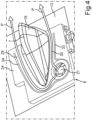
- Fig. 4 the view in Fig. 2 is shown in a top view.
- the components arranged below the outer roof 13 in the form of the control device 8 and the fan housing 19 are suggested.
- the housing 16 of the antenna unit 7 is already attached, which in Fig. 3 is taken off.
- FIG. 5 in a schematic sectional view an embodiment of an arrangement 6 is shown. Air P is suctioned from the passenger compartment 3 by the fan into the fan housing 19.
- the fan may be an axial fan. However, it may also be a radial fan.
- the fan housing 19 on the top side facing the control device 8 comprises an outlet 37. Same transitions directly into the inlet 38 of the flow channel 25. As can be discerned, the flow channel 25 on its entire length in the control device 8 is separate and thus decoupled from the receptacle 10. This means that no air conducted through the flow channel 25 is conducted through the receptacle 10.
- the first flow channel section 26, as already set out, extends from the bottom side 20 of the housing 9 up to the top side 24. There, the outlet 32 is then realized, at which the further flow channel section 27 ends.
Landscapes
- Engineering & Computer Science (AREA)
- Remote Sensing (AREA)
- Support Of Aerials (AREA)
- Fittings On The Vehicle Exterior For Carrying Loads, And Devices For Holding Or Mounting Articles (AREA)
Priority Applications (4)
| Application Number | Priority Date | Filing Date | Title |
|---|---|---|---|
| EP21192436.0A EP4138210B1 (fr) | 2021-08-20 | 2021-08-20 | Module d'antenne de toit comprenant un refroidissement spécifique d'un dispositif de commande sur un toit de véhicule, agencement, véhicule à moteur et procédé |
| US18/683,973 US12597693B2 (en) | 2021-08-20 | 2022-07-29 | Roof antenna module comprising a specific cooling of a control device on a vehicle roof, arrangement, motor vehicle, and method |
| CN202280054589.6A CN117795771A (zh) | 2021-08-20 | 2022-07-29 | 包括对车顶盖上的控制装置的特定冷却的车顶天线模块、布置、机动车辆和方法 |
| PCT/EP2022/071307 WO2023020806A1 (fr) | 2021-08-20 | 2022-07-29 | Module d'antenne de toit comprenant un refroidissement spécifique d'un dispositif de commande sur un toit de véhicule, agencement, véhicule à moteur et procédé |
Applications Claiming Priority (1)
| Application Number | Priority Date | Filing Date | Title |
|---|---|---|---|
| EP21192436.0A EP4138210B1 (fr) | 2021-08-20 | 2021-08-20 | Module d'antenne de toit comprenant un refroidissement spécifique d'un dispositif de commande sur un toit de véhicule, agencement, véhicule à moteur et procédé |
Publications (2)
| Publication Number | Publication Date |
|---|---|
| EP4138210A1 true EP4138210A1 (fr) | 2023-02-22 |
| EP4138210B1 EP4138210B1 (fr) | 2025-11-26 |
Family
ID=77431245
Family Applications (1)
| Application Number | Title | Priority Date | Filing Date |
|---|---|---|---|
| EP21192436.0A Active EP4138210B1 (fr) | 2021-08-20 | 2021-08-20 | Module d'antenne de toit comprenant un refroidissement spécifique d'un dispositif de commande sur un toit de véhicule, agencement, véhicule à moteur et procédé |
Country Status (4)
| Country | Link |
|---|---|
| US (1) | US12597693B2 (fr) |
| EP (1) | EP4138210B1 (fr) |
| CN (1) | CN117795771A (fr) |
| WO (1) | WO2023020806A1 (fr) |
Citations (4)
| Publication number | Priority date | Publication date | Assignee | Title |
|---|---|---|---|---|
| FR3060214A1 (fr) * | 2016-12-08 | 2018-06-15 | Valeo Comfort And Driving Assistance | Module d'antenne(s) pour vehicule automobile comprenant une feuille metallique |
| US20200185806A1 (en) | 2018-12-07 | 2020-06-11 | Intel Corporation | Cooling system for radio |
| JP2020195124A (ja) * | 2019-05-22 | 2020-12-03 | 株式会社デンソー | 電子装置 |
| US20200388910A1 (en) * | 2018-02-26 | 2020-12-10 | Denso Corporation | Vehicular antenna device |
Family Cites Families (1)
| Publication number | Priority date | Publication date | Assignee | Title |
|---|---|---|---|---|
| JP2021003954A (ja) * | 2019-06-25 | 2021-01-14 | 株式会社デンソー | 車載用電子装置 |
-
2021
- 2021-08-20 EP EP21192436.0A patent/EP4138210B1/fr active Active
-
2022
- 2022-07-29 WO PCT/EP2022/071307 patent/WO2023020806A1/fr not_active Ceased
- 2022-07-29 US US18/683,973 patent/US12597693B2/en active Active
- 2022-07-29 CN CN202280054589.6A patent/CN117795771A/zh active Pending
Patent Citations (4)
| Publication number | Priority date | Publication date | Assignee | Title |
|---|---|---|---|---|
| FR3060214A1 (fr) * | 2016-12-08 | 2018-06-15 | Valeo Comfort And Driving Assistance | Module d'antenne(s) pour vehicule automobile comprenant une feuille metallique |
| US20200388910A1 (en) * | 2018-02-26 | 2020-12-10 | Denso Corporation | Vehicular antenna device |
| US20200185806A1 (en) | 2018-12-07 | 2020-06-11 | Intel Corporation | Cooling system for radio |
| JP2020195124A (ja) * | 2019-05-22 | 2020-12-03 | 株式会社デンソー | 電子装置 |
Also Published As
| Publication number | Publication date |
|---|---|
| US12597693B2 (en) | 2026-04-07 |
| US20250141083A1 (en) | 2025-05-01 |
| EP4138210B1 (fr) | 2025-11-26 |
| WO2023020806A1 (fr) | 2023-02-23 |
| CN117795771A (zh) | 2024-03-29 |
Similar Documents
| Publication | Publication Date | Title |
|---|---|---|
| CN101815874B (zh) | 风扇马达单元 | |
| CN105473388B (zh) | 用于车辆的仪表板 | |
| US12090835B2 (en) | Arrangement of an air guiding element made of foam on a cooler element, and cooler element and air guiding element made of foam | |
| US20040094115A1 (en) | Assembly for cooling a control module and a battery | |
| EP4138210B1 (fr) | Module d'antenne de toit comprenant un refroidissement spécifique d'un dispositif de commande sur un toit de véhicule, agencement, véhicule à moteur et procédé | |
| US10995651B2 (en) | Exhaust system for a combustion engine of a motor vehicle and motor vehicle | |
| CN102862526A (zh) | 车辆的盖板装饰件的密封材料固定结构 | |
| CN114665647B (zh) | 驱动机组 | |
| US20040231898A1 (en) | Cooling system for an automotive drive unit | |
| CN112135742A (zh) | 车辆用空调装置 | |
| CZ20032761A3 (cs) | Kolejové poháněcí vozidlo s poháněcím ústrojím a hluk tlumicími prostředky | |
| US6406275B1 (en) | Cut for service motor with service ring | |
| US11338670B2 (en) | Transmission with power electronics module | |
| JP2006502905A (ja) | 自動車内の部品用空間 | |
| US20180278128A1 (en) | Heatsink and motor driving device | |
| JP2004245198A (ja) | 車載用電子制御装置 | |
| KR960011158A (ko) | 전동팬 | |
| CN113906838A (zh) | 用于制造包围控制器的壳体的方法 | |
| JP5911738B2 (ja) | カウルルーバー | |
| KR100403005B1 (ko) | 블로어 모터 조립구조 및 그 조립방법 | |
| JP7771604B2 (ja) | 車両前部構造 | |
| JP2020068225A (ja) | ダクトの排水構造 | |
| JP2009090745A (ja) | 車両のフロント構造 | |
| JP2003298255A (ja) | 電子制御機器 | |
| ATE439268T1 (de) | Luftführungsgehäuse für kraftfahrzeuge |
Legal Events
| Date | Code | Title | Description |
|---|---|---|---|
| PUAI | Public reference made under article 153(3) epc to a published international application that has entered the european phase |
Free format text: ORIGINAL CODE: 0009012 |
|
| STAA | Information on the status of an ep patent application or granted ep patent |
Free format text: STATUS: THE APPLICATION HAS BEEN PUBLISHED |
|
| AK | Designated contracting states |
Kind code of ref document: A1 Designated state(s): AL AT BE BG CH CY CZ DE DK EE ES FI FR GB GR HR HU IE IS IT LI LT LU LV MC MK MT NL NO PL PT RO RS SE SI SK SM TR |
|
| STAA | Information on the status of an ep patent application or granted ep patent |
Free format text: STATUS: REQUEST FOR EXAMINATION WAS MADE |
|
| 17P | Request for examination filed |
Effective date: 20230802 |
|
| RBV | Designated contracting states (corrected) |
Designated state(s): AL AT BE BG CH CY CZ DE DK EE ES FI FR GB GR HR HU IE IS IT LI LT LU LV MC MK MT NL NO PL PT RO RS SE SI SK SM TR |
|
| RAP3 | Party data changed (applicant data changed or rights of an application transferred) |
Owner name: VALEO COMFORT AND DRIVING ASSISTANCE |
|
| GRAP | Despatch of communication of intention to grant a patent |
Free format text: ORIGINAL CODE: EPIDOSNIGR1 |
|
| STAA | Information on the status of an ep patent application or granted ep patent |
Free format text: STATUS: GRANT OF PATENT IS INTENDED |
|
| INTG | Intention to grant announced |
Effective date: 20250911 |
|
| GRAS | Grant fee paid |
Free format text: ORIGINAL CODE: EPIDOSNIGR3 |
|
| GRAA | (expected) grant |
Free format text: ORIGINAL CODE: 0009210 |
|
| STAA | Information on the status of an ep patent application or granted ep patent |
Free format text: STATUS: THE PATENT HAS BEEN GRANTED |
|
| AK | Designated contracting states |
Kind code of ref document: B1 Designated state(s): AL AT BE BG CH CY CZ DE DK EE ES FI FR GB GR HR HU IE IS IT LI LT LU LV MC MK MT NL NO PL PT RO RS SE SI SK SM TR |
|
| REG | Reference to a national code |
Ref country code: CH Ref legal event code: F10 Free format text: ST27 STATUS EVENT CODE: U-0-0-F10-F00 (AS PROVIDED BY THE NATIONAL OFFICE) Effective date: 20251126 Ref country code: GB Ref legal event code: FG4D |
|
| REG | Reference to a national code |
Ref country code: DE Ref legal event code: R096 Ref document number: 602021042936 Country of ref document: DE |
|
| REG | Reference to a national code |
Ref country code: IE Ref legal event code: FG4D |
|
| REG | Reference to a national code |
Ref country code: NL Ref legal event code: MP Effective date: 20251126 |
|
| PG25 | Lapsed in a contracting state [announced via postgrant information from national office to epo] |
Ref country code: ES Free format text: LAPSE BECAUSE OF FAILURE TO SUBMIT A TRANSLATION OF THE DESCRIPTION OR TO PAY THE FEE WITHIN THE PRESCRIBED TIME-LIMIT Effective date: 20251126 |
|
| REG | Reference to a national code |
Ref country code: LT Ref legal event code: MG9D |
|
| PG25 | Lapsed in a contracting state [announced via postgrant information from national office to epo] |
Ref country code: NO Free format text: LAPSE BECAUSE OF FAILURE TO SUBMIT A TRANSLATION OF THE DESCRIPTION OR TO PAY THE FEE WITHIN THE PRESCRIBED TIME-LIMIT Effective date: 20260226 |
|
| PG25 | Lapsed in a contracting state [announced via postgrant information from national office to epo] |
Ref country code: HR Free format text: LAPSE BECAUSE OF FAILURE TO SUBMIT A TRANSLATION OF THE DESCRIPTION OR TO PAY THE FEE WITHIN THE PRESCRIBED TIME-LIMIT Effective date: 20251126 Ref country code: FI Free format text: LAPSE BECAUSE OF FAILURE TO SUBMIT A TRANSLATION OF THE DESCRIPTION OR TO PAY THE FEE WITHIN THE PRESCRIBED TIME-LIMIT Effective date: 20251126 Ref country code: AT Free format text: LAPSE BECAUSE OF FAILURE TO SUBMIT A TRANSLATION OF THE DESCRIPTION OR TO PAY THE FEE WITHIN THE PRESCRIBED TIME-LIMIT Effective date: 20251126 |
|
| REG | Reference to a national code |
Ref country code: AT Ref legal event code: MK05 Ref document number: 1862055 Country of ref document: AT Kind code of ref document: T Effective date: 20251126 |
|
| PG25 | Lapsed in a contracting state [announced via postgrant information from national office to epo] |
Ref country code: NL Free format text: LAPSE BECAUSE OF FAILURE TO SUBMIT A TRANSLATION OF THE DESCRIPTION OR TO PAY THE FEE WITHIN THE PRESCRIBED TIME-LIMIT Effective date: 20251126 |
|
| PG25 | Lapsed in a contracting state [announced via postgrant information from national office to epo] |
Ref country code: RS Free format text: LAPSE BECAUSE OF FAILURE TO SUBMIT A TRANSLATION OF THE DESCRIPTION OR TO PAY THE FEE WITHIN THE PRESCRIBED TIME-LIMIT Effective date: 20260226 |
|
| PG25 | Lapsed in a contracting state [announced via postgrant information from national office to epo] |
Ref country code: IS Free format text: LAPSE BECAUSE OF FAILURE TO SUBMIT A TRANSLATION OF THE DESCRIPTION OR TO PAY THE FEE WITHIN THE PRESCRIBED TIME-LIMIT Effective date: 20260326 |
|
| PG25 | Lapsed in a contracting state [announced via postgrant information from national office to epo] |
Ref country code: PT Free format text: LAPSE BECAUSE OF FAILURE TO SUBMIT A TRANSLATION OF THE DESCRIPTION OR TO PAY THE FEE WITHIN THE PRESCRIBED TIME-LIMIT Effective date: 20260326 |
|
| PG25 | Lapsed in a contracting state [announced via postgrant information from national office to epo] |
Ref country code: PL Free format text: LAPSE BECAUSE OF FAILURE TO SUBMIT A TRANSLATION OF THE DESCRIPTION OR TO PAY THE FEE WITHIN THE PRESCRIBED TIME-LIMIT Effective date: 20251126 |
|
| PG25 | Lapsed in a contracting state [announced via postgrant information from national office to epo] |
Ref country code: LV Free format text: LAPSE BECAUSE OF FAILURE TO SUBMIT A TRANSLATION OF THE DESCRIPTION OR TO PAY THE FEE WITHIN THE PRESCRIBED TIME-LIMIT Effective date: 20251126 |