EP4138212B1 - Unité d'antenne sans radôme - Google Patents
Unité d'antenne sans radôme Download PDFInfo
- Publication number
- EP4138212B1 EP4138212B1 EP22190591.2A EP22190591A EP4138212B1 EP 4138212 B1 EP4138212 B1 EP 4138212B1 EP 22190591 A EP22190591 A EP 22190591A EP 4138212 B1 EP4138212 B1 EP 4138212B1
- Authority
- EP
- European Patent Office
- Prior art keywords
- antenna
- cable
- antenna unit
- feed
- pressure vessel
- Prior art date
- Legal status (The legal status is an assumption and is not a legal conclusion. Google has not performed a legal analysis and makes no representation as to the accuracy of the status listed.)
- Active
Links
Images



Classifications
-
- H—ELECTRICITY
- H01—ELECTRIC ELEMENTS
- H01Q—ANTENNAS, i.e. RADIO AERIALS
- H01Q1/00—Details of, or arrangements associated with, antennas
- H01Q1/12—Supports; Mounting means
- H01Q1/22—Supports; Mounting means by structural association with other equipment or articles
- H01Q1/2208—Supports; Mounting means by structural association with other equipment or articles associated with components used in interrogation type services, i.e. in systems for information exchange between an interrogator/reader and a tag/transponder, e.g. in Radio Frequency Identification [RFID] systems
- H01Q1/2216—Supports; Mounting means by structural association with other equipment or articles associated with components used in interrogation type services, i.e. in systems for information exchange between an interrogator/reader and a tag/transponder, e.g. in Radio Frequency Identification [RFID] systems used in interrogator/reader equipment
-
- H—ELECTRICITY
- H01—ELECTRIC ELEMENTS
- H01Q—ANTENNAS, i.e. RADIO AERIALS
- H01Q21/00—Antenna arrays or systems
- H01Q21/06—Arrays of individually energised antenna units similarly polarised and spaced apart
- H01Q21/08—Arrays of individually energised antenna units similarly polarised and spaced apart the units being spaced along or adjacent to a rectilinear path
-
- H—ELECTRICITY
- H04—ELECTRIC COMMUNICATION TECHNIQUE
- H04Q—SELECTING
- H04Q9/00—Arrangements in telecontrol or telemetry systems for selectively calling a substation from a main station, in which substation desired apparatus is selected for applying a control signal thereto or for obtaining measured values therefrom
-
- H—ELECTRICITY
- H04—ELECTRIC COMMUNICATION TECHNIQUE
- H04Q—SELECTING
- H04Q2209/00—Arrangements in telecontrol or telemetry systems
- H04Q2209/40—Arrangements in telecontrol or telemetry systems using a wireless architecture
- H04Q2209/47—Arrangements in telecontrol or telemetry systems using a wireless architecture using RFID associated with sensors
Definitions
- the invention relates to antennas, mostly high-frequency antennas for the frequency range from 1 GHz to about 40 GHz, which both transmit and receive, as they are arranged in particular in pressure-tight rooms with a cable connection through the metallic wall of the pressure-tight room to the outside.
- a typical application is the pressure vessel of a freeze-drying system.
- the process temperature varies from approximately -70 °C to approximately +120 °C, and the process pressure varies from atmospheric pressure or even negative pressure to typically 3 bar above atmospheric pressure.
- an antenna of an antenna unit which usually includes an antenna at the level of each of the levels of the pressure vessel, sends out a request signal, which also supplies the temperature sensor, which does not have its own power supply, with the energy to not only measure the temperature, but also to send a response signal representing the measured temperature back to the antenna.
- a cable connection usually coaxial cables, leads from the antenna unit to the outside, which must be guided pressure-tight through the wall of the pressure vessel and connected outside the pressure vessel to an electronic query unit or the control unit of the freeze-drying system.
- the radome must be permeable to radio waves, so it must almost necessarily be made of plastic, while all other parts, especially the antenna base, are made of stainless steel due to existing hygiene regulations.
- freeze-drying plants want, if possible, that all additional fittings in the pressure vessel consist only of materials that are already present in the vessel and are therefore approved, especially from a hygienic point of view, since freeze-drying plants usually produce food or pharmaceuticals that are even more sensitive in terms of process conditions.
- the printed matter US 2021/047919 A1 discloses an antenna unit according to the preamble of claim 1. Furthermore, reference is made to the documents CN 211 350 926 U and US 2020/342186 A1 pointed out.
- the antenna unit - usually comprising several individual antennas - comprises, on the one hand, an antenna part, which also carries the several individual antennas, and a feed part, through which one or more cables, in particular high-frequency cables - which can each consist of several cable sections one behind the other - are fed in a protected manner to the antenna part and the antennas there.
- the antenna part is attached to the feed part by means of a flange block, and can be removed without destroying the connection, for example by loosening a screw connection, which should be possible in less than 1 to 2 minutes.
- a cable coupling be it a plug-in coupling or, in particular, a plug-in coupling, which additionally allows the release a union nut. This allows the cable sections of the feeder part to be very quickly detached from the cable sections of the antenna part.
- the feed section When installed in a pressure vessel, such as a freeze-drying system, the feed section can always remain permanently mounted, while the antenna section with the attached antennas can be easily detached and removed, either to replace a defective antenna or to improve access to components behind it in the pressure vessel.
- the antennas are usually high-frequency antennas, operating in the range of 1 GHz to 40 GHz, coaxial cables are used as cables and cable sections to prevent signal radiation through the cables themselves.
- tight means pressure-tight, i.e. gas-tight, especially in the case of pressure differences where the lowest pressure is in the negative pressure range of up to 1/10,000,00 bar, in particular 1/1,000,000 bar, and the highest pressure is in the positive pressure range of 5 bar overpressure and more.
- the pressure-tight separation between different rooms can be provided: On the one hand, the interior spaces of the feed part on the one hand and the antenna part on the other hand can be separated from each other in a pressure-tight manner by means of the closed flange block, which then of course requires a pressure-tight passage of the cable section there through the cable passage opening of the corresponding block part at least in one of the two block parts.
- the interior spaces of the feed part on the one hand and the antenna part on the other hand - regardless of whether they are pressure-tightly separated from each other when the flange block is closed or are pressure-connected to each other and form an interior space - are pressure-tightly sealed against the environment of the feed part on the one hand and/or the antenna part on the other hand.
- the interior of the feed part and/or the antenna part may still have a connection to the environment of the pressure chamber in such an assembled state.
- An SMA coupling is preferably used as the cable coupling, wherein the antenna-side coupling part of the cable coupling, in particular SMA coupling, is preferably not only fixed to the antenna part, in particular the antenna-side block part of the flange block, as is usual by screwing, but is also pressure-tightly glued or welded to it.
- the antenna part comprises a hollow, in particular tubular, support body, which is preferably made of metal, in particular stainless steel, wherein preferably the same material, in particular the same type of stainless steel, is used for the entire antenna unit as far as possible as for the pressure vessel itself.
- the corresponding cable sections are led from the flange block through the hollow support body to the usually several antennas that are tightly attached to the support body.
- a cable section coming from the flange block can also branch out in the support body and supply several antennas, which then activate the antennas with a time delay via an antenna multiplexer, which is usually included in the control system.
- the individual antennas are attached to, on, or above a respective opening in the wall of the support body, through which the cable reaches the back of the antenna, so that this opening is sealed pressure-tight by the antenna.
- the antenna is preferably made of the same material, preferably stainless steel, like the support body and can therefore be welded to the support body.
- the antenna unit and in particular its antenna part does not have a protective sheath in the form of a radome that surrounds the individual antennas in a pressure-tight manner and is connected in a pressure-tight manner to an antenna base or the antenna support body.
- the antenna part may have a protective device to protect the antennas present on the antenna part from damage in a purely mechanical manner, this does not provide a tight protective cover around the antenna part.
- the protective device can comprise only a grid or only protective rods running essentially parallel to the tubular support body and arranged around it outside the antennas, which do not pose a problem during the usually automatic cleaning of the interior of the pressure vessel, since they are accessible from all sides, usually drain freely downwards and cleaning fluid can drip freely downwards.
- a protective device such as a grid or protective rods is usually made of plastic, for example from PEEK or polyetheretherketone for reasons of mechanical strength.
- the individual antennas themselves usually consist of a - usually plate-shaped - radiator, i.e. the actual transmitter and receiver of the antenna, as well as a reflector plate arranged behind it at a distance against the direction of radiation, which is usually larger than the plate-shaped radiator and whose task is to reflect the electromagnetic waves of the response signal arriving in the area around the radiator in the direction of the radiator and thus to improve, in particular to amplify, its useful signal.
- both the reflector plate and a plate-shaped radiator can have a variety of openings.
- the antenna protection tube can form the reflector in whole or in part.
- both the reflector plate and the radiator and/or the spacer sleeve are made of the same material, in particular the same material as the pressure vessel.
- a coupling part of a cable coupling is attached to the rear side of the reflector plate facing away from the radiator, to which the cable section in the support body can be connected, e.g. plugged, before or after welding the reflector plate to the support body to seal the corresponding opening.
- the distance between the reflector plate and the radiator can be bridged by a cable section running between the reflector plate and the radiator - which is in particular firmly and permanently attached to the radiator, for example soldered or welded - or by this cable coupling being designed in such a way that it extends from the back of the reflector plate through it and to the back of the radiator, where the inner conductor of the coaxial cable couples the high-frequency oscillation into the radiator.
- Cable couplings are possible with a capacitive high-frequency coupling of the inner conductors on both sides via a link made of an electrical insulator, for example so-called glass bushings, in which the electrical insulator, for example a glass plate or glass sphere, is welded pressure-tight into the surrounding coupling housing, reaches to both sides of the inner conductor and contacts it, thereby passing the high frequency of the applied alternating current across the electrical insulator.
- an electrical insulator for example so-called glass bushings
- a cable coupling can consist of two coupling parts, each with a cable section attached, which are then coupled together by directly connecting the two coupling parts to each other.
- a cable coupling can also have three coupling parts, namely an additional middle piece - which is often designed as an adapter - on each side of which one of the two further coupling parts connected to a cable section is attached.
- a radially projecting coupling flange which serves for fixing, in particular screwing, to a component of the surroundings, whereby the entire coupling is then positioned.
- the radiator can also be detachably attached to the reflector plate, in particular screwed, in particular by means of spacers which are mounted at a distance, in particular offset, from the cable connection.
- the hollow support body is thus circumferentially closed by its walls and the openings therein, which are sealed pressure-tight by the antennas, at one end by a block part of the flange block, and at the opposite end by a substantially closed end wall.
- the hollow support body - in the lower region, in particular at the lowest point, of the hollow support body - in the case of an upright tubular support body which is tightly connected to the feed part at the upper end, in the lower end wall - there is an access opening which can, however, be closed in a pressure-tight manner, for example by being designed as a threaded opening into which a sealing plug can be tightly screwed.
- This access opening which is closed during normal operation, can be used for different purposes when open:
- a gassing device can be tightly connected to it, through which an inert gas such as helium can be introduced into the interior of the support body in order to detect in the area surrounding the support body by means of appropriate sensors whether this gas is present there, which could then only have gotten there through a leak in the support body.
- a leak test can also be carried out in other ways, for example by pressurising the interior of the support body via the access opening with gas at a predetermined holding pressure, which must not fall below a defined threshold value within a specified time.
- Condensation can also be drained through such an access opening.
- the flange block which tightly connects the two parts of the antenna unit, usually comprises two cap-shaped block parts that can be pressed tightly against each other, in particular screwed together pressure-tight, each with a through-opening for the cable(s).
- the free interior space created by the two block sections pressed against each other with their cap edges is large enough to accommodate a cable coupling, with one coupling part being attached to each of the cables inserted into the flange block through one of the through-holes.
- the feed section and antenna section are tightly separated from one another with regard to their interior spaces when the flange block is tightly closed, so that even when the antenna section is removed, the interior of the feed section is not opened, and preferably vice versa.
- the feed section with its open connectors can be hermetically sealed with a sealing cap.
- Welded in this case means that only a circumferential welding of the coupling part relative to the block part is required, not a welding all around.
- the two block parts consist of the same material, in particular the same material as the adjacent feed part and/or support part of the antenna part, in particular stainless steel, and preferably the same material as the pressure vessel.
- the feed part has a tubular feed body that is open on both sides and in which runs at least one cable that connects the control unit to the radiator of the antenna.
- one of the block parts of the flange block is attached, in particular welded, in a pressure-tight manner to one of the open ends of the feed body, namely the antenna-side end.
- the feed body At the opposite end of the feed body, away from the antenna, there is a wall feedthrough with which the feed body can extend through a corresponding recess in the wall of the pressure vessel and can be sealed against this wall.
- This wall feedthrough can be an integral part of the feed body, for example, by being an annular plate that is tightly welded to the outer circumference of the tubular feed body in order to be sealed and fixed to the wall of the pressure vessel around a change passage.
- the wall feedthrough is preferably made of the same material as the feed body to which it is attached.
- the supply part can be a shaped part such as a straight or curved, circumferentially pressure-tight pipe, or a circumferentially pressure-tight, flexible hose such as a stainless steel corrugated hose.
- a straight pipe would be preferable, but is not always feasible, since the desired position of the antenna part in the pressure vessel, for example, is usually not aligned with the opening in the wall for the feed part.
- the antenna part and/or the feed part can also comprise a dehumidification unit in order to, for example, remove condensation in its interior to remove or bind any moisture that has arisen, for example by means of a moisture-absorbing substance such as silica gel.
- a dehumidification unit in order to, for example, remove condensation in its interior to remove or bind any moisture that has arisen, for example by means of a moisture-absorbing substance such as silica gel.
- this antenna part can be moved, in particular pivoted, from its operating position to a parking position even when the antenna unit is fully assembled, preferably together with the feed part.
- the support body of the antenna part can be pivoted about its greatest extension direction, i.e. its longitudinal axis, relative to the feed part even in the fully assembled state of the antenna unit and can be fixed in any desired pivot position.
- a freeze-drying system usually comprises a temperature-controlled and pressure-controllable pressure vessel and an electronic control system arranged outside the pressure vessel, whereby an antenna unit can be arranged inside the pressure vessel in order to wirelessly query the temperature from a plurality of temperature sensors arranged therein, positioned in the product or its containers.
- the latter preferably comprises a holding device inside it, to which the antenna unit, preferably only its antenna part, can be fastened detachably and movably, but fixable in any possible position.
- the wall opening in the wall of the pressure vessel for the antenna unit can be designed - depending on the size and shape of the wall opening of the antenna unit - in such a way that the antenna unit, in particular its feed part, can be inserted through the wall opening from the inside or from the outside.
- the antenna is welded onto the opening.
- the antenna-side end of the cable can be connected to the antenna by detachable contact or detachably only by destroying the connection, in particular by soldering or welding.
- the supply part is inserted from the outside into the wall passage of the pressure vessel and fixed pressure-tight against the wall of the pressure vessel.
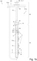
- the Figures 1a , b show that the antenna unit 1 consists of two elongated, bar-shaped parts, which follow one another in the axial direction, namely the antenna part 50, on which the antennas 2 are located, and the feed part 60.
- the purpose of the design is to make the antenna unit 1 itself sealed, including the passage of the cables through the passage 102 of the pressure vessel 100, in order to thereby access the sealed cover hood, usually referred to as a radome, attached to the inside of the wall of the pressure vessel - as in Figure 1b indicated by dashed lines - and to ensure better assembly and accessibility to antenna unit 1.
- connections between the hollow tubular feed body 61 of the feed part 60 and the hollow support body 51 of the antenna part 50 which is open at least on one side, must be designed to be tight, as must the fastening of the antennas 2 on the outside of the support body 51.
- the main direction of extension of the antenna unit 1 i.e. the direction in which it has its size of extension, is defined as the longitudinal direction 1' and is usually identical with the longitudinal direction 50' of the antenna part 50, since its supporting body 51 is usually straight, while the feed body 61 can also be bent one or more times, as in Figure 1a visible. Since the antenna unit 1 is often mounted suspended from an upper wall 101a of the pressure vessel 101, the longitudinal direction 1' is often identical to the vertical 10.
- the feed body 61 is usually first inserted into the passage 102 of the wall 101a of the pressure vessel 101, usually inserted into the passage 102 from the outside of the pressure vessel 101.
- the prefabricated antenna part 50 is then attached to it, i.e. the support body 51 with the antennas 2 attached thereto, including the cable sections 3.50 of the cables 3 that are already connected to the antennas and are located in the support body 51 and extend to the upper open end of the support body 51.
- the antenna part 50 comprises a hollow, tubular - in this case with a rectangular cross-section - support body 51 and the feed part 60 a hollow feed body 61, because the antennas 2 must each be connected with a cable 3 - as on the uppermost of the four antennas 2 in Figure 1b shown as an example - which, from bottom to top, runs first in the support body 51 and then in the feed body 61 and extends through a passage 102 in the wall 101a of a pressure vessel 101, so that the cable is connected outside the pressure vessel 1 with a Figure 4 indicated electronic interrogation system 1 * of the antenna unit 1 of the system to which the pressure vessel 101 belongs.
- Figure 1b further shows in the upper area of the feed body 61 on the outside thereof a dehumidification unit 90 with a dehumidification container 91 with a moisture-absorbing ingredient, which is in communication with the interior of the feed body 61 and absorbs moisture present there.
- the upper, open end of the hollow support body 51 is tightly connected to the lower, open end of the feed body 61 by means of a coupling block 70 which has two block parts 70a, b which can be pressed tightly against each other in the longitudinal direction 50'.
- the lower block part 70a is placed on the upper end face of the support body 51 and welded to it in a sealed manner all around, whereby this plate-shaped, lower block part 70a is usually shell-shaped with an upwardly open depression, but above all has passages running in the longitudinal direction 50', into each of which an intermediate piece 4c is screwed, preferably tightly, which has a coupling part both on the side of the feed body 61 and on the side of the support body 51, onto which a coupling part 4a, b can be screwed at the end of a cable section 3.50 or a cable section 3.60.
- the upper, annular block part 70b can be pressed from above against a radially outwardly projecting, annular flange 63 at the lower end of the feed part 61 and this onto a seal 64 which is located between this flange 63 and the lower block part 70a.
- the cable sections 3.50 leading from below from the support body 51 are electrically connected to the cable sections 3.60 leading from above from the feed body 61 via the cable couplings 4, usually an SMA coupling.
- the individual antennas 2 each consist of a reflector plate 21, which is fastened tightly to the support body 51, and a radiator 22, which may be plate-shaped and is located on the front side 21a of the reflector plate 21 facing away from the support body 51 and at a distance from it.
- the radiator 22 is screwed via, in this case, two screw connections 24 through spacer sleeves 25 arranged between the radiator 22 and the reflector plate 21, at a position at which the radiator 22 oscillating with the applied high frequency has a wave node.
- An angle piece 14c is screwed onto the coupling part 14a of the respective antenna 2, which projects from the rear of the coupling piece 15 and thus transversely to the longitudinal direction 50', to which a cable section 3.50 can be fastened via a coupling part 14b, which runs from there inside the support body 51 to its open end facing the feed body 61.
- Figure 2a further shows that the four cable couplings for connecting each 3.50 cable section to each 3.60 cable section are arranged in a square. Within the passage of the block section.
- Figure 2a further shows the purely mechanical protective device 8 around the antenna unit 1, which here consists of protective rods 9 extending in the axial direction 1' and distributed in a circle around the outside of the antenna unit 1 of which one runs next to the side edge of the reflector plates 21 running in the longitudinal direction 50' of the antenna part 50.
- the space inside such a pressure vessel 101 is usually very limited, as it contains a number of internal components that frequently require maintenance and repairs.
- the protective device 8 prevents damage to the antenna unit 1 by a technician or a moving part in the pressure vessel 101.
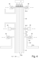
- the Figure 4 shows the fastening of the feed body 61 to the wall 101a of the pressure vessel 101 in such a way that the cable sections 3.60 located therein extend through the passage 102 in the wall 101a of the pressure vessel 101, wherein the passage 102 must be large enough to allow the flange 63 at the lower end of the feed body 61 to pass through when inserted from the outside.
- the feed body 61 has, at its end region facing away from the antenna, not only a flange 61b projecting radially outwards from its wall in a ring shape, but also a further flange 61a set back from it.
- the flanges 61a and 103 lie axially on one another and can be pressed together radially tightly, for example by a clamping device 80 pressed from the radial outside - if necessary with a seal arranged between them.
- clamping devices 80 consist of two hinged half-rings, each having a U-shaped cross-section, wherein the free ends of the half-rings can be pressed against each other by a clamping screw.
- the axial pressing of the flanges against each other is achieved by the conical flanks of the U-shaped cross-section and the similarly conical outer sides of the two flanges to be pressed against each other, facing away from the other flange, which thus become thinner radially outward.
- the flange 61b present at the end of the feed body 61 serves, for example, to be able to tightly attach a flange 65.1 of a tubular extension part 65, be it a straight sleeve or a T-piece as shown in the left half of the figure, through which the cable sections 3.60 can continue to run.
- the continuation part 65 can also be a cover plate closing the front opening of the feed part 61, to or in which the free ends of the cable sections 3.60 are fastened with corresponding plug parts or socket parts.
Landscapes
- Engineering & Computer Science (AREA)
- Computer Networks & Wireless Communication (AREA)
- Details Of Aerials (AREA)
Claims (21)
- Unité d'antenne (1) avec- une partie antenne (50) comprenant plusieurs antennes individuelles (2),- une partie d'alimentation (60) pour l'alimentation protégée d'au moins un câble (3) avec plusieurs sections de câble (3.50, 3.60) vers la partie antenne (50),caractérisée en ce que- la partie antenne (50) est fixée de manière amovible à la partie d'alimentation (60) au moyen d'un bloc à bride (70), mais étanche à la pression, donc étanche aux gaz, même au vide, à l'environnement autour des parties (50, 60, 70) de l'unité d'antenne (1)- la section de câble (3.60) de la partie d'alimentation (60) étant fixée de manière facilement amovible au moyen d'un raccord de câble (4), à la section de câble (3.50) de la partie antenne (50).
- Unité d'antenne selon la revendication 1,
caractérisée en ce que- le câble (3) est un câble coaxial
et/ou- le raccord de câble (4) est un raccord haute fréquence ou un raccord SMA,- dont la partie de raccord côté antenne (4a) est notamment soudée ou vissée dans la partie antenne (50). - Unité d'antenne selon l'une des revendications précédentes,
caractérisée en ce que
la partie antenne (50) comprend :- un corps de support creux (51), en particulier tubulaire, qui est en particulier en métal, de préférence en acier inoxydable,- au moins une antenne (2), qui est fixée au corps de support (51) et ferme ainsi de manière étanche à la pression un passage (5) dans la paroi (51a) du corps de support (51). - Unité d'antenne selon la revendication 3,
caractérisée en ce que
la partie de l'antenne (2) fixée au corps de support (51) est constituée du même matériau que le corps de support (51) et est soudée ou collée à celui-ci. - Unité d'antenne selon l'une des revendications précédentes,
caractérisée en ce que- la partie antenne (50) ne comporte pas de gaine de protection entourant étroitement ladite au moins une antenne (2),
ou- la partie antenne (50) comporte un dispositif de protection qui n'entoure pas étroitement l'antenne (2),- qui est constitué essentiellement, de préférence uniquement, de tiges de protection disposées autour de la partie antenne (50), par exemple en PEEK. - Unité d'antenne selon l'une des revendications précédentes,
caractérisée en ce que- l'antenne (2) comprend une plaque réflectrice (21) ainsi qu'un radiateur (22) disposé à distance devant celle-ci,- la plaque réflectrice (21) en particulier est fixée, en particulier soudée, au corps de support (51) de manière à fermer hermétiquement le passage (5). - Unité d'antenne selon les revendications 3 et 6 et, si on le souhaite, selon la revendication 4 ou 5,
caractérisée en ce que- au moins la plaque réflectrice (21) et/ou le radiateur (22) et/ou le corps de support (51) sont fabriqués du même matériau et en particulier du même matériau que le récipient sous pression (101), en particulier en acier inoxydable, en particulier du type 1.4.4.2004/AISI 31GL-FDA/GMP ou 1.4.4.2004/AINSI 316L,
et/ou- le radiateur (22) est fixé de manière amovible à la plaque réflectrice (21). - Unité d'antenne selon la revendication 6 et, si on le souhaite, selon la revendication 7,
caractérisée en ce que- une partie d'accouplement (14a) d'un coupleur de câble (14) est disposée dans un passage de la plaque réflectrice (21) ou à l'arrière (21b) de la plaque réflectrice (21) devant un passage (5), laquelle partie d'accouplement dépasse de l'arrière de la partie d'accouplement (13) vers l'intérieur du corps de support (51) et que- la partie d'accouplement (14a) est reliée électriquement au radiateur (22) par l'intermédiaire d'une partie d'accouplement (13) qui comprend notamment une broche d'accouplement (15), en particulier de manière permanente, c'est-à-dire de manière non détachable sans détruire la connexion, en particulier par brasage ou soudage. - Unité d'antenne selon la revendication 6 et, si on le souhaite, selon la revendication 7 ou 8,
caractérisée en ce que- une ouverture d'accès (7) est présente dans la partie inférieure, en particulier au point le plus bas, en particulier dans la paroi frontale inférieure du corps de support (51),- l'ouverture d'accès est conçue en particulier comme une ouverture filetée (7) pouvant être fermée de manière étanche,- qui est particulièrement adaptée au raccordement d'un dispositif de gazage, par exemple pour un test d'étanchéité. - Unité d'antenne selon l'une des revendications précédentes,
caractérisée en ce que- le bloc à bride (70) comporte deux parties de bloc (70a, b) pouvant être pressées l'une contre l'autre de manière étanche, en particulier vissées, en particulier en forme de capuchon avec au moins une ouverture de passage pour le câble (3) chacune,- l'espace intérieur libre du bloc à bride (70) est suffisamment grand pour accueillir au moins un raccord de câble (4), en particulier- au moins l'une des parties de raccord (4a, b, c), en particulier une partie intermédiaire de raccord (4c) est fixée dans l'une des parties de bloc (70a, b) , en particulier de manière étanche, en particulier par soudage ou vissage étanche,
et/ou- les deux parties de bloc (70a, b) sont constituées du même matériau, en particulier de métal, en particulier de l'acier inoxydable. - Unité d'antenne selon l'une des revendications précédentes,
caractérisée en ce que
la partie d'alimentation (60)- présente un corps d'alimentation (61) tubulaire ouvert des deux côtés, dans lequel passe ledit au moins un câble (3),- présente l'une des parties de bloc (70b) ou une bride (63), qui est fixée de manière étanche, en particulier soudée, à l'extrémité côté antenne du corps d'alimentation (61),- présente un passage mural (62) à l'extrémité du corps d'alimentation (61) opposée à l'antenne, qui fait partie intégrante du corps d'alimentation (61) ou qui est relié de manière étanche à la périphérie de celui-ci. - Unité d'antenne selon l'une des revendications précédentes,
caractérisée en ce que
la partie de bloc (70b) est constituée du même matériau que le corps d'alimentation (61). - Unité d'antenne selon l'une des revendications précédentes,
caractérisée en ce que
la partie d'alimentation (60) est- un tube rigide, droit ou courbé, ou- un tuyau flexible, étanche sur toute sa circonférence, en particulier un tuyau ondulé, en particulier en acier inoxydable. - Unité d'antenne selon l'une des revendications précédentes,
caractérisée en ce que- la partie antenne (50) et/ou la partie d'alimentation (60) comprend une unité de déshumidification (90),- en particulier une substance absorbant l'humidité telle que du gel de silice est disposée de manière remplaçable dans un récipient de déshumidification (91), qui est relié de manière étanche à l'intérieur de la partie (50, 60). - Unité d'antenne selon l'une des revendications précédentes,
caractérisée en ce que- la partie antenne (50) peut être pivotée et fixée autour de son axe principal (50') par rapport à la partie d'alimentation (60) lorsque l'unité d'antenne (1) est complètement assemblée,- en particulier au moyen d'un bloc à bride (70) ou d'un passage de câble (62) conçu comme un accouplement rotatif. - Installation de lyophilisation (100) avec- un récipient sous pression (101) pouvant être tempéré,- une commande électronique (100*) disposée à l'extérieur du récipient sous pression (101),- une unité d'antenne (1) avec- une partie antenne (50) disposée dans le récipient sous pression (101),- une partie d'alimentation (60), dont le corps d'alimentation (61) est équipé d'un passage de câble (62) allant de l'unité d'antenne (50) à la commande (100*) ou à l'unité d'interrogation électronique (1*) pour les antennes (2) à travers la paroi du récipient sous pression (101),caractérisé en ce que- l'unité d'antenne (1) est conçue selon l'une des revendications précédentes.
- Installation de lyophilisation selon la revendication 16,
caractérisée en ce que
un dispositif de maintien est prévu à l'intérieur du récipient sous pression (101) pour fixer, en particulier de manière amovible ou mobile, en particulier de manière supplémentaire, l'unité d'antenne (100), en particulier sa partie antenne (50), au récipient sous pression (101). - Procédé de fabrication d'une unité d'antenne (1) avec une partie antenne (50) et une partie d'alimentation (60) pour câble (3) vers la partie antenne (50) selon la revendication 3 et, si souhaité, selon l'une des revendications 4 à 15,
caractérisé en ce que
pour fabriquer la partie antenne (50)- le câble (3) est introduit dans le corps de support (51) de la partie antenne (50),- l'extrémité côté antenne (3a) du câble (3) sortant du passage (5) est reliée à l'antenne (2), en particulier à sa partie d'accouplement (13),- l'antenne (2) est fixée de manière étanche sur ou dans le passage (5) pour la fermer. - Procédé selon la revendication 18,
caractérisé en ce que- l'extrémité côté antenne du câble (3) est reliée à l'antenne (2) par un contact amovible ou seulement en détruisant la connexion, en particulier par brasage ou soudage,
et/ou- l'antenne (2), en particulier sa partie d'accouplement (13), est soudée sur ou dans le passage (5). - Procédé de montage d'une unité d'antenne (1) selon l'une des revendications 1 à 15, dans un récipient sous pression (101), en particulier une installation de lyophilisation (100) selon l'une des revendications 16 ou 17,
caractérisé en ce que- la partie d'alimentation (60) est fixée de manière étanche dans le passage de paroi du récipient sous pression (101) avec au moins une section de câble (3.60) à l'intérieur,- la partie antenne (50) est positionnée avant ou après avec au moins une section de câble (3.50) à l'intérieur dans une position de référence dans le récipient sous pression (101) et est fixée en particulier à un dispositif de maintien du récipient sous pression (1),- la partie d'alimentation (60) et la partie antenne (50) sont reliées entre elles par un bloc à bride (70) de manière étanche à la pression et au niveau de leurs sections de câble (3.50 et 3.60). - Procédé selon la revendication 20,
caractérisé en ce que
la partie d'alimentation (60) est insérée de l'extérieur dans le passage de paroi (102) de la paroi (101a) du récipient sous pression (101) et est fixée de manière étanche à la pression par rapport à la paroi (101a) du récipient sous pression (101).
Applications Claiming Priority (1)
| Application Number | Priority Date | Filing Date | Title |
|---|---|---|---|
| DE102021121430.0A DE102021121430A1 (de) | 2021-08-18 | 2021-08-18 | Radom-freie Antennen-Einheit |
Publications (3)
| Publication Number | Publication Date |
|---|---|
| EP4138212A1 EP4138212A1 (fr) | 2023-02-22 |
| EP4138212C0 EP4138212C0 (fr) | 2025-05-07 |
| EP4138212B1 true EP4138212B1 (fr) | 2025-05-07 |
Family
ID=82939685
Family Applications (1)
| Application Number | Title | Priority Date | Filing Date |
|---|---|---|---|
| EP22190591.2A Active EP4138212B1 (fr) | 2021-08-18 | 2022-08-16 | Unité d'antenne sans radôme |
Country Status (3)
| Country | Link |
|---|---|
| EP (1) | EP4138212B1 (fr) |
| DE (1) | DE102021121430A1 (fr) |
| ES (1) | ES3032489T3 (fr) |
Families Citing this family (1)
| Publication number | Priority date | Publication date | Assignee | Title |
|---|---|---|---|---|
| WO2025157968A1 (fr) | 2024-01-25 | 2025-07-31 | Iq-Mobil Gmbh | Commande ou régulation d'un lyophilisateur sur la base d'une détection d'une augmentation caractéristique de température en référence à au moins un flacon d'échantillon parmi une pluralité de flacons soumis à un processus de lyophilisation |
Family Cites Families (3)
| Publication number | Priority date | Publication date | Assignee | Title |
|---|---|---|---|---|
| US11288465B2 (en) * | 2018-01-11 | 2022-03-29 | Shell Oil Company | Wireless monitoring and profiling of reactor conditions using plurality of sensor-enabled RFID tags having known locations |
| GB201802054D0 (en) * | 2018-02-08 | 2018-03-28 | Welldata Subsurface Surveillance Systems Ltd | Downhole detection |
| CN211350926U (zh) * | 2019-12-27 | 2020-08-25 | 石家庄恒军通信技术有限公司 | 三频天线 |
-
2021
- 2021-08-18 DE DE102021121430.0A patent/DE102021121430A1/de active Pending
-
2022
- 2022-08-16 ES ES22190591T patent/ES3032489T3/es active Active
- 2022-08-16 EP EP22190591.2A patent/EP4138212B1/fr active Active
Also Published As
| Publication number | Publication date |
|---|---|
| EP4138212A1 (fr) | 2023-02-22 |
| ES3032489T3 (en) | 2025-07-21 |
| EP4138212C0 (fr) | 2025-05-07 |
| DE102021121430A1 (de) | 2023-02-23 |
Similar Documents
| Publication | Publication Date | Title |
|---|---|---|
| EP3168581B1 (fr) | Antenne a cornet et appareil de mesure de niveau de remplissage radar dote d'une antenne a cornet | |
| EP4138212B1 (fr) | Unité d'antenne sans radôme | |
| DE102006003742A1 (de) | Vorrichtung zur Ermittlung und Überwachung des Füllstandes eines Mediums in einem Behälter | |
| DE4038273A1 (de) | Vorrichtung zum ausloesen und/oder foerdern chemischer und/oder physikalischer prozesse | |
| EP2871450B1 (fr) | Antenne chauffée | |
| EP2752941A1 (fr) | Antenne parabolique ayant un sous-réflecteur intégré dans le radôme | |
| EP0459085A1 (fr) | Méthode d'assemblage pour vacuum-éléments d'isolation thermique | |
| WO2017089550A1 (fr) | Boîtier protégé contre les explosions pour moyens d'émission et de réception de rayonnement électromagnétique | |
| EP2561518A1 (fr) | Isolateur haute tension | |
| DE102010049788B4 (de) | Ausdrückvorrichtung | |
| DE102011112123B4 (de) | Druckentlastungsvorrichtung für ein Berstelement | |
| EP2359098B1 (fr) | Convertisseur de mesure de pression différentielle | |
| DE4405855A1 (de) | Antenneneinrichtung für ein Füllstandmeßgerät | |
| DE102008060654B4 (de) | Endlagerbehäter und Verfahren zur Einbringung eines Gegenstands in denselben | |
| EP4004498B1 (fr) | Dispositif de mesure pour déterminer une variable de procédé dans un récipient | |
| EP0758619A1 (fr) | Récipient pour le stockage de liquides | |
| EP3407080A1 (fr) | Tête d'échantillon nmr à joint hf détachable | |
| DE4312261A1 (de) | Sammelschienenkupplung | |
| DE102024107222A1 (de) | Schutzrohr, Temperatursensorvorrichtung mit einem Schutzrohr und doppelwandiges Rohr oder Behälter | |
| CH694688A5 (de) | Verfahren zum Transport von mindestens einer dampffoermigen Substanz durch die Wand einer Vakuumkammer in die Vakuumkammer sowie Vorrichtung zur Durchfuehrung des Verfahrens und deren Verwendu | |
| EP3748312B1 (fr) | Appareil de mesure à bride et récipient avec cet appareil de mesure | |
| EP2258972B1 (fr) | Elément avec bride et son procédé de fabrication | |
| EP4038352A1 (fr) | Adaptateur hygiénique pour instrument de terrain | |
| EP4170298A1 (fr) | Appareil de mesure radar, dispositif de mesure et lentille | |
| WO2012159826A1 (fr) | Procédé de réparation ou de vérification d'une installation, en particulier frigorifique, logée dans un contenant fermé de manière étanche à la pression et contenant permettant de mettre en œuvre le procédé |
Legal Events
| Date | Code | Title | Description |
|---|---|---|---|
| PUAI | Public reference made under article 153(3) epc to a published international application that has entered the european phase |
Free format text: ORIGINAL CODE: 0009012 |
|
| STAA | Information on the status of an ep patent application or granted ep patent |
Free format text: STATUS: THE APPLICATION HAS BEEN PUBLISHED |
|
| AK | Designated contracting states |
Kind code of ref document: A1 Designated state(s): AL AT BE BG CH CY CZ DE DK EE ES FI FR GB GR HR HU IE IS IT LI LT LU LV MC MK MT NL NO PL PT RO RS SE SI SK SM TR |
|
| P01 | Opt-out of the competence of the unified patent court (upc) registered |
Effective date: 20230519 |
|
| STAA | Information on the status of an ep patent application or granted ep patent |
Free format text: STATUS: REQUEST FOR EXAMINATION WAS MADE |
|
| 17P | Request for examination filed |
Effective date: 20230821 |
|
| RBV | Designated contracting states (corrected) |
Designated state(s): AL AT BE BG CH CY CZ DE DK EE ES FI FR GB GR HR HU IE IS IT LI LT LU LV MC MK MT NL NO PL PT RO RS SE SI SK SM TR |
|
| GRAP | Despatch of communication of intention to grant a patent |
Free format text: ORIGINAL CODE: EPIDOSNIGR1 |
|
| STAA | Information on the status of an ep patent application or granted ep patent |
Free format text: STATUS: GRANT OF PATENT IS INTENDED |
|
| RIC1 | Information provided on ipc code assigned before grant |
Ipc: H04Q 9/00 20060101ALN20241022BHEP Ipc: H01Q 21/08 20060101ALI20241022BHEP Ipc: H01Q 1/22 20060101AFI20241022BHEP |
|
| INTG | Intention to grant announced |
Effective date: 20241118 |
|
| GRAS | Grant fee paid |
Free format text: ORIGINAL CODE: EPIDOSNIGR3 |
|
| GRAA | (expected) grant |
Free format text: ORIGINAL CODE: 0009210 |
|
| STAA | Information on the status of an ep patent application or granted ep patent |
Free format text: STATUS: THE PATENT HAS BEEN GRANTED |
|
| RAP3 | Party data changed (applicant data changed or rights of an application transferred) |
Owner name: TEMPRIS GMBH |
|
| AK | Designated contracting states |
Kind code of ref document: B1 Designated state(s): AL AT BE BG CH CY CZ DE DK EE ES FI FR GB GR HR HU IE IS IT LI LT LU LV MC MK MT NL NO PL PT RO RS SE SI SK SM TR |
|
| REG | Reference to a national code |
Ref country code: GB Ref legal event code: FG4D Free format text: NOT ENGLISH |
|
| REG | Reference to a national code |
Ref country code: CH Ref legal event code: EP |
|
| REG | Reference to a national code |
Ref country code: DE Ref legal event code: R096 Ref document number: 502022003845 Country of ref document: DE |
|
| REG | Reference to a national code |
Ref country code: IE Ref legal event code: FG4D Free format text: LANGUAGE OF EP DOCUMENT: GERMAN |
|
| U01 | Request for unitary effect filed |
Effective date: 20250526 |
|
| U07 | Unitary effect registered |
Designated state(s): AT BE BG DE DK EE FI FR IT LT LU LV MT NL PT RO SE SI Effective date: 20250603 |
|
| P04 | Withdrawal of opt-out of the competence of the unified patent court (upc) registered |
Free format text: CASE NUMBER: APP_25708/2025 Effective date: 20250528 |
|
| REG | Reference to a national code |
Ref country code: ES Ref legal event code: FG2A Ref document number: 3032489 Country of ref document: ES Kind code of ref document: T3 Effective date: 20250721 |
|
| U20 | Renewal fee for the european patent with unitary effect paid |
Year of fee payment: 4 Effective date: 20250728 |
|
| PGFP | Annual fee paid to national office [announced via postgrant information from national office to epo] |
Ref country code: ES Payment date: 20250926 Year of fee payment: 4 |
|
| PG25 | Lapsed in a contracting state [announced via postgrant information from national office to epo] |
Ref country code: GR Free format text: LAPSE BECAUSE OF FAILURE TO SUBMIT A TRANSLATION OF THE DESCRIPTION OR TO PAY THE FEE WITHIN THE PRESCRIBED TIME-LIMIT Effective date: 20250808 Ref country code: NO Free format text: LAPSE BECAUSE OF FAILURE TO SUBMIT A TRANSLATION OF THE DESCRIPTION OR TO PAY THE FEE WITHIN THE PRESCRIBED TIME-LIMIT Effective date: 20250807 |
|
| PG25 | Lapsed in a contracting state [announced via postgrant information from national office to epo] |
Ref country code: PL Free format text: LAPSE BECAUSE OF FAILURE TO SUBMIT A TRANSLATION OF THE DESCRIPTION OR TO PAY THE FEE WITHIN THE PRESCRIBED TIME-LIMIT Effective date: 20250507 |
|
| PG25 | Lapsed in a contracting state [announced via postgrant information from national office to epo] |
Ref country code: HR Free format text: LAPSE BECAUSE OF FAILURE TO SUBMIT A TRANSLATION OF THE DESCRIPTION OR TO PAY THE FEE WITHIN THE PRESCRIBED TIME-LIMIT Effective date: 20250507 |
|
| PG25 | Lapsed in a contracting state [announced via postgrant information from national office to epo] |
Ref country code: RS Free format text: LAPSE BECAUSE OF FAILURE TO SUBMIT A TRANSLATION OF THE DESCRIPTION OR TO PAY THE FEE WITHIN THE PRESCRIBED TIME-LIMIT Effective date: 20250807 |
|
| PG25 | Lapsed in a contracting state [announced via postgrant information from national office to epo] |
Ref country code: IS Free format text: LAPSE BECAUSE OF FAILURE TO SUBMIT A TRANSLATION OF THE DESCRIPTION OR TO PAY THE FEE WITHIN THE PRESCRIBED TIME-LIMIT Effective date: 20250907 |
|
| PG25 | Lapsed in a contracting state [announced via postgrant information from national office to epo] |
Ref country code: SM Free format text: LAPSE BECAUSE OF FAILURE TO SUBMIT A TRANSLATION OF THE DESCRIPTION OR TO PAY THE FEE WITHIN THE PRESCRIBED TIME-LIMIT Effective date: 20250507 |
|
| PG25 | Lapsed in a contracting state [announced via postgrant information from national office to epo] |
Ref country code: CZ Free format text: LAPSE BECAUSE OF FAILURE TO SUBMIT A TRANSLATION OF THE DESCRIPTION OR TO PAY THE FEE WITHIN THE PRESCRIBED TIME-LIMIT Effective date: 20250507 |
|
| PG25 | Lapsed in a contracting state [announced via postgrant information from national office to epo] |
Ref country code: SK Free format text: LAPSE BECAUSE OF FAILURE TO SUBMIT A TRANSLATION OF THE DESCRIPTION OR TO PAY THE FEE WITHIN THE PRESCRIBED TIME-LIMIT Effective date: 20250507 |
|
| PLBE | No opposition filed within time limit |
Free format text: ORIGINAL CODE: 0009261 |
|
| STAA | Information on the status of an ep patent application or granted ep patent |
Free format text: STATUS: NO OPPOSITION FILED WITHIN TIME LIMIT |
|
| REG | Reference to a national code |
Ref country code: CH Ref legal event code: L10 Free format text: ST27 STATUS EVENT CODE: U-0-0-L10-L00 (AS PROVIDED BY THE NATIONAL OFFICE) Effective date: 20260318 |
|
| REG | Reference to a national code |
Ref country code: CH Ref legal event code: H13 Free format text: ST27 STATUS EVENT CODE: U-0-0-H10-H13 (AS PROVIDED BY THE NATIONAL OFFICE) Effective date: 20260324 |
|
| PG25 | Lapsed in a contracting state [announced via postgrant information from national office to epo] |
Ref country code: MC Free format text: LAPSE BECAUSE OF FAILURE TO SUBMIT A TRANSLATION OF THE DESCRIPTION OR TO PAY THE FEE WITHIN THE PRESCRIBED TIME-LIMIT Effective date: 20250507 |
|
| 26N | No opposition filed |
Effective date: 20260210 |
|
| PG25 | Lapsed in a contracting state [announced via postgrant information from national office to epo] |
Ref country code: CH Free format text: LAPSE BECAUSE OF NON-PAYMENT OF DUE FEES Effective date: 20250831 |