EP4138214A1 - Dispositif portable - Google Patents
Dispositif portable Download PDFInfo
- Publication number
- EP4138214A1 EP4138214A1 EP21817560.2A EP21817560A EP4138214A1 EP 4138214 A1 EP4138214 A1 EP 4138214A1 EP 21817560 A EP21817560 A EP 21817560A EP 4138214 A1 EP4138214 A1 EP 4138214A1
- Authority
- EP
- European Patent Office
- Prior art keywords
- metal
- wearable device
- metal frame
- antenna
- bezel
- Prior art date
- Legal status (The legal status is an assumption and is not a legal conclusion. Google has not performed a legal analysis and makes no representation as to the accuracy of the status listed.)
- Granted
Links
Images



Classifications
-
- H—ELECTRICITY
- H01—ELECTRIC ELEMENTS
- H01Q—ANTENNAS, i.e. RADIO AERIALS
- H01Q1/00—Details of, or arrangements associated with, antennas
- H01Q1/27—Adaptation for use in or on movable bodies
- H01Q1/273—Adaptation for carrying or wearing by persons or animals
-
- G—PHYSICS
- G04—HOROLOGY
- G04G—ELECTRONIC TIME-PIECES
- G04G17/00—Structural details; Housings
- G04G17/02—Component assemblies
- G04G17/04—Mounting of electronic components
-
- G—PHYSICS
- G04—HOROLOGY
- G04R—RADIO-CONTROLLED TIME-PIECES
- G04R60/00—Constructional details
- G04R60/06—Antennas attached to or integrated in clock or watch bodies
- G04R60/10—Antennas attached to or integrated in clock or watch bodies inside cases
- G04R60/12—Antennas attached to or integrated in clock or watch bodies inside cases inside metal cases
-
- H—ELECTRICITY
- H01—ELECTRIC ELEMENTS
- H01Q—ANTENNAS, i.e. RADIO AERIALS
- H01Q1/00—Details of, or arrangements associated with, antennas
- H01Q1/48—Earthing means; Earth screens; Counterpoises
-
- H—ELECTRICITY
- H01—ELECTRIC ELEMENTS
- H01Q—ANTENNAS, i.e. RADIO AERIALS
- H01Q1/00—Details of, or arrangements associated with, antennas
- H01Q1/52—Means for reducing coupling between antennas; Means for reducing coupling between an antenna and another structure
-
- H—ELECTRICITY
- H01—ELECTRIC ELEMENTS
- H01Q—ANTENNAS, i.e. RADIO AERIALS
- H01Q13/00—Waveguide horns or mouths; Slot antennas; Leaky-waveguide antennas; Equivalent structures causing radiation along the transmission path of a guided wave
- H01Q13/10—Resonant slot antennas
-
- H—ELECTRICITY
- H01—ELECTRIC ELEMENTS
- H01Q—ANTENNAS, i.e. RADIO AERIALS
- H01Q21/00—Antenna arrays or systems
- H01Q21/28—Combinations of substantially independent non-interacting antenna units or systems
-
- H—ELECTRICITY
- H01—ELECTRIC ELEMENTS
- H01Q—ANTENNAS, i.e. RADIO AERIALS
- H01Q5/00—Arrangements for simultaneous operation of antennas on two or more different wavebands, e.g. dual-band or multi-band arrangements
- H01Q5/30—Arrangements for providing operation on different wavebands
- H01Q5/307—Individual or coupled radiating elements, each element being fed in an unspecified way
Definitions
- the present disclosure relates to the field of electronics technologies, and in particular to a wearable device.
- smart wearable devices are becoming more and more popular among users due to diverse functions thereof.
- the smart watches in addition to the basic timekeeping function, the smart watches generally integrate numerous functions such as motion assistance, trajectory positioning, connection with smart terminals, and phone calls. All these functions may be implemented by means of built-in antennas of the watches. Therefore, how to improve the antenna performance of the wearable devices has always been one of the most important research directions.
- Implementations of the present disclosure provide a wearable device.
- an implementation of the present disclosure provides a wearable device, comprising:
- each of the metal frame and the metal bezel has an annular shape
- the first direction is a circumferential direction of the metal frame
- the distance between two adjacent connectors along the first direction is a corresponding arc length between the two adjacent connectors.
- the plurality of connectors are arranged uniformly along the first direction.
- an insulating filler structure is filled between the metal frame and the metal bezel.
- the one or more antennas of the wearable device comprise at least one of: a Bluetooth antenna, a satellite positioning antenna, a WiFi antenna, an LTE antenna, or a 5G antenna.
- an assembly step is provided on a side edge of the metal frame close to the metal bezel, a lug protruding toward the metal frame is formed on an edge of the metal bezel, and the metal bezel is provided on the assembly step of the metal frame through the lug.
- the connector is a metal spring piece, one end of the metal spring piece is fixed to the metal frame, and the other end of the metal spring piece abuts elastically against an inner wall of the lug of the metal bezel.
- the metal frame is provided with an assembly hole, and the one end of the metal spring piece is fixed in the assembly hole.
- the one end of the metal spring piece is welded to the metal frame.
- the connector is a snap integrally formed on the assembly step, and a protrusion that abuts against an inner wall of the lug is formed on a side of the snap facing the lug of the metal bezel.
- the wearable device is a smart watch or a smart wristband.
- the wearable device comprises the metal frame and the metal bezel.
- the metal frame is disposed around the side of the device, and the gap between the metal frame and the mainboard of the wearable device forms the antenna of the wearable device, while the metal bezel is disposed around the front edge of the device, and the metal bezel and the metal frame are electrically connected to each other through the plurality of connectors, such that the bezel may be electrically connected to the frame at predetermined positions to improve the consistency of the antenna, and the performance of the antenna may not be affected even if some additional electrical contact points are created between the frame and the bezel at uncertain positions during use of the wearable device.
- the distance between any two adjacent connectors along the first direction is less than 1/4 of the wavelength corresponding to the maximum operating frequency of the one or more antennas. Since the length of the gap for generating electromagnetic wave resonance is required to be at least 1/4 of the resonant wavelength, if the distance between any two adjacent connectors is less than 1/4 of the wavelength corresponding to the maximum operating frequency of the antennas, clutter interference can be effectively avoided and the radiation performance of the antenna can be greatly improved.
- a wearable device is applicable to any type of device suitable for implementation, for example, a wrist-worn device such as a smart watch or a smart wristband; a head-mounted device such as smart glasses or smart earphones; and a wearable device such as smart clothing; etc.
- the wearable device is exemplified hereinafter as a smart watch.
- the following implementations are also applicable to other types of wearable devices, which are not limited in the present disclosure.
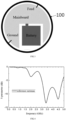
- FIGS. 1 and 2 illustrate a structure of a smart watch in the related art.
- an exterior portion of the smart watch includes a metal frame 100 and a metal bezel 200.
- the metal frame 100 is an annular metal middle frame, which is disposed around a side of the watch.
- the metal frame 100 not only serves as a case structure of the watch, but also forms a slot antenna structure with a mainboard of the watch.
- a smart watch with a metal middle frame
- its antenna structure is generally formed by using a gap between the metal frame 100 and the mainboard of the watch.
- the metal middle frame is provided with a grounding point and connected to a feeding module on the mainboard, such that a corresponding antenna structure is formed.
- the metal bezel 200 mainly plays two roles in the smart watch.
- a screen 300 may be fixedly assembled with the metal frame 100 by means of a step, while a portion of the step supporting an edge of the screen 300 cannot be used as a display area and appears as a "black edge” in the appearance of the watch.
- the "black edge” is undoubtedly unacceptable to users, and manufacturers are committed to removing the "black edge”.
- the metal bezel 200 at the position of the "black edge”
- the "black edge” may be covered by a metal exterior, which greatly improves the texture of the appearance and enhances the user experience.
- the metal bezel 200 as an annular outer ring of the watch, is provided with a variety of functions thereon, such as, for example, adding a time scale as an indicator scale of the watch; adding various ruler-type scales as additional functions of the watch; and providing various decorative structures and patterns as the appearance of the watch.
- the metal bezel 200 On the basis of the roles of the metal bezel, more and more smart watches are provided with the metal bezel 200 on the front, and the metal bezel 200 is fixedly connected with the metal frame 100 by filling an adhesive between the metal bezel 200 and the metal frame 100.
- the inventors of this application found that such smart watches with the metal bezel 200 have poor antenna consistency and performance.
- the gap is electrically isolated by filling the gap with a dielectric material such as an adhesive, during the actual use of the watch, for example, when a portion of the metal bezel 200 is squeezed, the metal bezel 200 contacts with the metal frame 100 electrically at a single point or multiple points in unfixed positions.
- the electrical contact at a single point and the electrical contact at multiple points with a large spacing damage the original antenna performance, thereby affecting the function of the whole watch system.
- the antenna structure in this example is referred to as "reference antenna”.
- An antenna with a relatively broad band is selected as the reference antenna with a structure shown in FIG. 3 . That is, this antenna structure is implemented by the gap between the metal frame 100 and the mainboard in the watch. Those skilled in the art may understand this antenna structure and its operating principle, which will not be repeated herein.
- FIG. 4 illustrates a graph of a return loss (an S-parameter) of the reference antenna without providing the metal bezel 200.
- FIG. 5 illustrates a graph of a return loss of the reference antenna with the rotation of the electrical contact point P1 between the metal bezel 200 and the metal frame 100.
- the return loss of the reference antenna varies greatly with the position of the electrical contact point P1, and a lot of clutter may appear at multiple positions throughout the whole range of the frequency band, and the position of the clutter may change with the position of the electrical contact point P1. It can be clearly known from the test results that the consistency and performance of the antenna cannot be guaranteed due to the uncertainty of the electrical contact point, which undoubtedly greatly affects the function of the antenna system of the watch.
- implementations of the present disclosure provide a wearable device.
- the main technical solution of the present disclosure is that the metal frame 100 and the metal bezel 200 are electrically connected to each other through a plurality of connectors, such that the bezel is electrically connected to the frame at predetermined positions, and the number and positions of electrical connection points are optimized to improve the consistency and performance of the antenna. Even if some additional electrical contact points are created between the frame and the bezel at uncertain positions during use, the performance of the antenna is not affected.
- the wearable device is still exemplified by the smart watch shown in FIG. 1 .
- the smart watch includes an annular metal frame 100 and an annular metal bezel 200.
- the metal frame 100 is disposed around a side of the watch and serves as an antenna radiator, and a gap between the metal frame 100 and a mainboard of the wearable device forms an antenna of the wearable device.
- the metal bezel 200 is disposed around a front edge of the watch, and the metal bezel 200 is electrically connected to the metal frame 100 through a plurality of connectors.
- a distance between any adjacent two of the plurality of connectors along a first direction is less than 1/4 of a wavelength corresponding to a maximum operating frequency of one or more antennas, the first direction being a direction around the metal frame 100, i.e., the first direction being a peripheral direction of the metal frame 100.
- the connectors serve to enable the metal bezel 200 and the metal frame 100 to be electrically connected at positions where the connectors are provided.
- the connector may be a metal sheet provided in the gap between the metal bezel 200 and the metal frame 100.
- the watch often includes a plurality of antennas with different electromagnetic wave operating frequencies, such as Bluetooth antenna and satellite positioning antenna, and the term "the wavelength corresponding to the maximum operating frequency” refers to a wavelength of the antenna having the maximum operating frequency among these antennas. This will be described in detail below, and will not be discussed herein.
- first direction is the peripheral direction of the metal frame 100.
- first direction is a circumferential direction of the metal frame 100
- distance along the first direction refers to an arc length of a surface of the metal frame 100 where the connectors are provided.
- frames with other shapes such as rectangle, diamond, triangle, or other irregular shapes, which can be understood by those skilled in the art.
- the metal bezel 200 and the metal frame 100 are electrically connected to each other through the plurality of connectors provided between the metal bezel 200 and the metal frame 100, such that the metal bezel 200 is electrically connected to the metal frame 100 at predetermined positions to ensure the consistency of the antenna, and the performance of the antenna is not affected even if some additional electrical contact points are created between the metal frame 100 and the metal bezel 200 at uncertain positions during use.
- the distance between any two adjacent connectors along the first direction is less than 1/4 of the wavelength corresponding to the maximum operating frequency of the one or more antennas.
- the length of the gap for generating electromagnetic wave resonance is required to be at least 1/4 of the resonant wavelength, if the distance between any two adjacent connectors is less than 1/4 of the wavelength corresponding to the maximum operating frequency of the antennas, clutter interference can be effectively avoided and the radiation performance of the antenna can be greatly improved.
- the design of the wearable device according to the present disclosure mainly includes two parts: first, the number and position distribution of electrical connection points (i.e., the connectors); and second, a specific structure for realizing the electrical connection. These two parts will be described in detail below in conjunction with a specific implementation.
- the basic requirement for the slot antenna to produce the operating resonance is that the length of the gap is at least 1/4 of the resonant wavelength, such as a 1/4 wavelength slot antenna with one end open, and a 1/2 wavelength slot antenna, which can be understood by those skilled in the art and will not repeated herein.
- C refers to light speed.
- the arc length of the gap formed between two adjacent connectors should be guaranteed to be less than 1/4 of the wavelength corresponding to the maximum operating frequency of the antennas.
- the maximum arc length among the arc lengths of the gaps formed between two adjacent connectors should be guaranteed to be less than 1/4 of the wavelength corresponding to the maximum operating frequency of the antennas.
- the arc length of each of the gaps should be guaranteed to be less than 1/4 of the wavelength corresponding to the maximum operating frequency of the antennas.
- the plurality of connectors are uniformly distributed along the first direction.
- the number of the connectors may be determined based on a diameter or circumference of the watch.
- the smart watch in the implementation of FIG. 1 is still taken as an example, the number of the connectors is set to four, and the four connectors are uniformly distributed along the circumferential direction.
- FIG. 7 illustrates a graph of a return loss of the antenna in this example.
- the four connectors are rotated clockwise by different angles of 0°, 30°, and 60° to obtain the graph as shown in FIG. 7 .
- the smart watch generally includes a Bluetooth antenna, a WiFi antenna, and a satellite positioning antenna.
- a central operating frequency of the Bluetooth antenna and WiFi antenna is 2.4GHz
- the central operating frequency of the satellite positioning antenna (GPS antenna) for general civil use is 1.575GHz.
- the Bluetooth antenna having the maximum operating frequency its wavelength in the air is about 125mm, and 1/4 of the wavelength is about 30mm.
- the arc length between two adjacent connectors is about 40mm. That is, the distance between two adjacent connectors is 40mm, which is greater than 1/4 of the wavelength corresponding to the maximum operating frequency, i.e., 30mm. Therefore, clutter may still be produced for the Bluetooth and WiFi antennas with the frequency of 2.4GHz.
- the arc length between two adjacent connectors needs to be less than 1/4 of the wavelength corresponding to the maximum operating frequency. For instance, in the above example, as long as the arc length between two adjacent connectors is less than 30mm, it is guaranteed that the antenna has better consistency and performance in the range of the frequency lower than 2.4GHz. That is, at least six connectors are arranged around the circumference of the metal frame 100. In the case that the six connectors are uniformly arranged, the arc length between two adjacent connectors is about 26mm, which can fully meet the requirements.
- the clutter only appears in the range of frequency greater than 3.2GHz, while the antenna has better consistency and performance in the range of frequency lower than 3.2GHz.
- good performance in the range of frequency below 3.2GHz is sufficient to meet the design requirements of the 2.4GHz Bluetooth antenna.
- the metal frame 100 and the metal bezel 200 are electrically connected by means of the connectors in this implementation.
- the distance between two adjacent connectors has already met the design requirements. Therefore, even if the metal bezel 200 is squeezed and the metal bezel 200 is electrically connected with the metal frame 100 at more electrical connection points, which is equivalent to increasing the number of the electrical connection points on the basis of this implementation, the performance of the antenna is not affected and the above effects described in this implementation can still be achieved based on the above principle.
- the primary technical solution of the implementations of the present disclosure is to set the distance between any two adjacent connectors along the first direction to be less than 1/4 of the wavelength corresponding to the maximum operating frequency of one or more antennas.
- the wearable device may further include a 4G LTE antenna with an operating frequency ranging from 0.7GHz to 2.69GHz, a WiFi 5.8GHz antenna, a 5G n77 antenna with an operating frequency ranging from 3.3GHz to 4.2GHz, etc.
- the distance between any two adjacent connectors is made less than 1/4 of the wavelength corresponding to the maximum operating frequency by increasing the number of the connectors, and the type and operating frequency of the antenna are not limited. This can be understood by those skilled in the art, and will not be repeated in the present disclosure.
- the smart watch shown in FIG. 1 is still taken as an example.
- the metal frame 100 is fastened to the metal bezel 200 by an assembly boss.
- an annular assembly step is provided around the metal frame 100, and a lug is formed around an edge of the metal bezel 200, so as to achieve the assembly of the metal bezel 200 and the metal frame 100 via the fit between the lug and the assembly step.
- An assembly gap between the metal bezel 200 and the metal frame 100 needs to be filled with an insulating adhesive to form a filler structure.
- the filler structure may insulate the metal bezel 200 from the metal frame 100 on the one hand, and may bond and fix the metal bezel 200 to the metal frame 100 on the other hand.
- the connector in the implementations of the present disclosure may be provided in the gap where the metal bezel 200 abuts against the metal frame 100, and an electrical connection point is formed through the connector to electrically connect the metal bezel 200 and the metal frame 100.
- the connectors 500 include six metal spring pieces uniformly disposed on the metal frame 100.
- six assembly holes are provided in the metal frame 100, and each of the metal spring pieces is mounted in a respective assembly hole.
- One end of the metal spring piece is fixed in the assembly hole, and the other end of the metal spring piece abuts elastically against an inner wall of the lug of the metal bezel 200.
- This electrical connection method is applicable to the metal frame 100 made of material such as titanium alloy or aluminum alloy which is difficult to weld.
- the connectors 500 also include six metal spring pieces uniformly disposed on the metal frame 100.
- FIGS. 10A and 10B differ from FIGS. 9A and 9B in that, one end of the metal spring piece is fixedly connected to the metal frame 100 by welding, and the other end of the metal spring piece abuts elastically against the inner wall of the lug of the metal bezel 200.
- This electrical connection method is applicable to the metal frame 100 made of material such as stainless steel which is easy to weld.
- the metal spring piece exerts an elastic force on the metal bezel 200 in a radially outward direction of the watch, such that the metal spring piece may also exert a radially outward force after the metal bezel 200 is assembled with the metal frame 100, making the metal bezel 200 assembled more firmly, while making the electrical connection between the metal bezel 200 and the metal frame 100 more stable.
- FIGS. 11A and 11B the structure of the connectors is shown in FIGS. 11A and 11B .
- the connectors are snaps 510 integrally formed on the assembly step of the metal frame 100, and six snaps 510 are uniformly distributed around the circumference of the metal frame 100.
- a protrusion 520 is formed on a side wall of the snap 510 facing the lug of the metal bezel 200, such that the protrusion 520 abuts against the inner wall of the lug of the metal bezel 200 after the metal bezel 200 is assembled with the metal frame 100 to achieve the electrical connection between the metal bezel 200 and the metal frame 100.
- This electrical connection method is applicable to the metal frame 100 made of any metal material.
- the structure and setting of the connectors may be in any other form suitable for implementation, which can be understood by those skilled in the art and will not be enumerated in the present disclosure.
- the wearable device is described by taking the smart watch as an example, the wearable device in the present disclosure is not limited to the smart watch, but may be any other wearable device suitable for implementation, which is not limited in the present disclosure.
- the metal bezel 200 and the metal frame 100 are electrically connected to each other through the plurality of connectors provided between the metal bezel 200 and the metal frame 100, such that the metal bezel 200 is electrically connected to the metal frame 100 at predetermined positions to ensure the consistency of the antenna, and the performance of the antenna is not affected even if some additional electrical contact points may be created between the metal frame 100 and the metal bezel 200 at uncertain positions during use.
- the distance between any two adjacent connectors along the first direction is less than 1/4 of the wavelength corresponding to the maximum operating frequency of the one or more antennas.
- the length of the gap for generating electromagnetic wave resonance is required to be at least 1/4 of the resonant wavelength, if the distance between any two adjacent connectors is less than 1/4 of the wavelength corresponding to the maximum operating frequency of the antennas, clutter interference can be effectively avoided and the radiation performance of the antenna can be greatly improved.
Landscapes
- Physics & Mathematics (AREA)
- General Physics & Mathematics (AREA)
- Electric Clocks (AREA)
- Support Of Aerials (AREA)
Applications Claiming Priority (3)
| Application Number | Priority Date | Filing Date | Title |
|---|---|---|---|
| CN202010506277.7A CN111613872B (zh) | 2020-06-05 | 2020-06-05 | 可穿戴设备 |
| CN202021019018.3U CN212412191U (zh) | 2020-06-05 | 2020-06-05 | 可穿戴设备 |
| PCT/CN2021/098164 WO2021244612A1 (fr) | 2020-06-05 | 2021-06-03 | Dispositif portable |
Publications (3)
| Publication Number | Publication Date |
|---|---|
| EP4138214A1 true EP4138214A1 (fr) | 2023-02-22 |
| EP4138214A4 EP4138214A4 (fr) | 2023-10-18 |
| EP4138214B1 EP4138214B1 (fr) | 2025-10-01 |
Family
ID=78830128
Family Applications (1)
| Application Number | Title | Priority Date | Filing Date |
|---|---|---|---|
| EP21817560.2A Active EP4138214B1 (fr) | 2020-06-05 | 2021-06-03 | Dispositif portable |
Country Status (4)
| Country | Link |
|---|---|
| US (1) | US11764460B2 (fr) |
| EP (1) | EP4138214B1 (fr) |
| ES (1) | ES3048609T3 (fr) |
| WO (1) | WO2021244612A1 (fr) |
Families Citing this family (3)
| Publication number | Priority date | Publication date | Assignee | Title |
|---|---|---|---|---|
| CN115693138B (zh) * | 2021-07-28 | 2026-08-11 | 华为技术有限公司 | 穿戴式电子设备机芯、外壳及穿戴式电子设备 |
| USD1038119S1 (en) * | 2022-06-01 | 2024-08-06 | Zepp, Inc. | Watch |
| CN116014423A (zh) * | 2023-02-09 | 2023-04-25 | 歌尔股份有限公司 | 一种天线及可穿戴设备 |
Family Cites Families (19)
| Publication number | Priority date | Publication date | Assignee | Title |
|---|---|---|---|---|
| US7079079B2 (en) * | 2004-06-30 | 2006-07-18 | Skycross, Inc. | Low profile compact multi-band meanderline loaded antenna |
| JP5712814B2 (ja) * | 2010-11-12 | 2015-05-07 | セイコーエプソン株式会社 | アンテナ内蔵式電子時計 |
| GB2570905B (en) * | 2018-02-08 | 2021-10-20 | Suunto Oy | Slot mode antennas |
| US10693218B2 (en) * | 2014-07-01 | 2020-06-23 | Microsoft Technology Licensing, Llc | Structural tank integrated into an electronic device case |
| KR102177285B1 (ko) * | 2014-09-01 | 2020-11-10 | 삼성전자주식회사 | 안테나 장치 및 그것을 포함하는 전자 장치 |
| US10126780B2 (en) * | 2015-01-29 | 2018-11-13 | Huawei Technologies Co., Ltd. | Slot antenna for a wearable device |
| CN106486737A (zh) * | 2015-09-02 | 2017-03-08 | 中兴通讯股份有限公司 | 一种手表天线和手表 |
| KR20170089668A (ko) * | 2016-01-27 | 2017-08-04 | 엘지전자 주식회사 | 안테나를 구비하는 와치 타입의 이동 단말기 |
| CN105789844A (zh) * | 2016-04-12 | 2016-07-20 | 深圳市中易腾达科技股份有限公司 | 一种一体化金属边框天线 |
| CN105785757B (zh) * | 2016-04-28 | 2018-05-01 | 歌尔股份有限公司 | 手表天线装置及电子手表 |
| KR102584972B1 (ko) * | 2016-08-29 | 2023-10-05 | 삼성전자주식회사 | 다중 대역 안테나를 포함하는 웨어러블 전자 장치 |
| KR102567892B1 (ko) * | 2016-09-05 | 2023-08-17 | 삼성전자주식회사 | 안테나를 포함하는 전자 장치 |
| KR102591805B1 (ko) * | 2016-11-04 | 2023-10-23 | 삼성전자주식회사 | 웨어러블 전자 장치의 안테나 |
| TWI623149B (zh) * | 2016-11-10 | 2018-05-01 | 和碩聯合科技股份有限公司 | 穿戴式電子裝置及其天線系統 |
| US10276934B2 (en) * | 2017-03-02 | 2019-04-30 | Wistron Neweb Corporation | Antenna structure |
| TWI798344B (zh) * | 2018-02-08 | 2023-04-11 | 芬蘭商順妥公司 | 槽孔模式天線 |
| CN209860131U (zh) * | 2018-12-29 | 2019-12-27 | Oppo广东移动通信有限公司 | 电子设备 |
| CN111613872B (zh) * | 2020-06-05 | 2025-06-24 | 安徽华米健康科技有限公司 | 可穿戴设备 |
| CN212412191U (zh) * | 2020-06-05 | 2021-01-26 | 安徽华米信息科技有限公司 | 可穿戴设备 |
-
2021
- 2021-06-03 EP EP21817560.2A patent/EP4138214B1/fr active Active
- 2021-06-03 ES ES21817560T patent/ES3048609T3/es active Active
- 2021-06-03 WO PCT/CN2021/098164 patent/WO2021244612A1/fr not_active Ceased
-
2022
- 2022-11-18 US US17/990,461 patent/US11764460B2/en active Active
Also Published As
| Publication number | Publication date |
|---|---|
| EP4138214A4 (fr) | 2023-10-18 |
| US11764460B2 (en) | 2023-09-19 |
| WO2021244612A1 (fr) | 2021-12-09 |
| EP4138214B1 (fr) | 2025-10-01 |
| ES3048609T3 (en) | 2025-12-11 |
| US20230082798A1 (en) | 2023-03-16 |
Similar Documents
| Publication | Publication Date | Title |
|---|---|---|
| US11764460B2 (en) | Wearable devices | |
| US20230231311A1 (en) | Circularly Polarized Antennas And Wearable Devices | |
| JP6005321B2 (ja) | 多目的アンテナ | |
| CN111916898B (zh) | 圆极化天线结构及智能穿戴设备 | |
| US20260051652A1 (en) | Circularly Polarized Antenna Structures And Wearable Devices | |
| CN111613872B (zh) | 可穿戴设备 | |
| CN115411498B (zh) | 穿戴设备 | |
| US12482927B2 (en) | Circularly polarized antenna structures and wearable devices | |
| CN111628283A (zh) | 天线结构及可穿戴设备 | |
| CN212412191U (zh) | 可穿戴设备 | |
| CN212783791U (zh) | 圆极化天线结构及智能穿戴设备 | |
| CN116780193A (zh) | 一种可穿戴设备 | |
| TW201727998A (zh) | 穿戴式裝置 | |
| CN111916887A (zh) | 可穿戴设备及其天线加工方法 | |
| CN104536288A (zh) | 一种采用新型天线的卫星授时手表 | |
| CN111463552A (zh) | 一种手表 | |
| CN211088496U (zh) | 一种智能手表 | |
| CN212257676U (zh) | 天线结构及可穿戴设备 | |
| CN113258252B (zh) | 天线结构和通信设备 | |
| CN215645010U (zh) | 一种天线结构及电子设备 | |
| CN110364809B (zh) | 穿戴式电子设备 | |
| CN215070375U (zh) | 天线结构和通信设备 | |
| CN106532229B (zh) | 一种全金属手表天线 | |
| TWM550916U (zh) | 電子裝置及其天線模組 | |
| CN216529327U (zh) | 一种用于智能手表的超宽频通信天线及智能手表 |
Legal Events
| Date | Code | Title | Description |
|---|---|---|---|
| STAA | Information on the status of an ep patent application or granted ep patent |
Free format text: STATUS: THE INTERNATIONAL PUBLICATION HAS BEEN MADE |
|
| PUAI | Public reference made under article 153(3) epc to a published international application that has entered the european phase |
Free format text: ORIGINAL CODE: 0009012 |
|
| STAA | Information on the status of an ep patent application or granted ep patent |
Free format text: STATUS: REQUEST FOR EXAMINATION WAS MADE |
|
| 17P | Request for examination filed |
Effective date: 20221117 |
|
| AK | Designated contracting states |
Kind code of ref document: A1 Designated state(s): AL AT BE BG CH CY CZ DE DK EE ES FI FR GB GR HR HU IE IS IT LI LT LU LV MC MK MT NL NO PL PT RO RS SE SI SK SM TR |
|
| DAV | Request for validation of the european patent (deleted) | ||
| DAX | Request for extension of the european patent (deleted) | ||
| A4 | Supplementary search report drawn up and despatched |
Effective date: 20230914 |
|
| RIC1 | Information provided on ipc code assigned before grant |
Ipc: H01Q 21/28 20060101ALI20230908BHEP Ipc: H01Q 5/307 20150101ALI20230908BHEP Ipc: H01Q 1/52 20060101ALI20230908BHEP Ipc: H01Q 13/10 20060101ALI20230908BHEP Ipc: H01Q 1/27 20060101AFI20230908BHEP |
|
| RAP1 | Party data changed (applicant data changed or rights of an application transferred) |
Owner name: ANHUI HUAMI HEALTH TECHNOLOGY CO., LTD. |
|
| GRAP | Despatch of communication of intention to grant a patent |
Free format text: ORIGINAL CODE: EPIDOSNIGR1 |
|
| STAA | Information on the status of an ep patent application or granted ep patent |
Free format text: STATUS: GRANT OF PATENT IS INTENDED |
|
| INTG | Intention to grant announced |
Effective date: 20250624 |
|
| GRAS | Grant fee paid |
Free format text: ORIGINAL CODE: EPIDOSNIGR3 |
|
| GRAA | (expected) grant |
Free format text: ORIGINAL CODE: 0009210 |
|
| STAA | Information on the status of an ep patent application or granted ep patent |
Free format text: STATUS: THE PATENT HAS BEEN GRANTED |
|
| AK | Designated contracting states |
Kind code of ref document: B1 Designated state(s): AL AT BE BG CH CY CZ DE DK EE ES FI FR GB GR HR HU IE IS IT LI LT LU LV MC MK MT NL NO PL PT RO RS SE SI SK SM TR |
|
| P01 | Opt-out of the competence of the unified patent court (upc) registered |
Free format text: CASE NUMBER: UPC_APP_3938_4138214/2025 Effective date: 20250821 |
|
| REG | Reference to a national code |
Ref country code: GB Ref legal event code: FG4D Ref country code: CH Ref legal event code: F10 Free format text: ST27 STATUS EVENT CODE: U-0-0-F10-F00 (AS PROVIDED BY THE NATIONAL OFFICE) Effective date: 20251001 |
|
| REG | Reference to a national code |
Ref country code: IE Ref legal event code: FG4D |
|
| REG | Reference to a national code |
Ref country code: DE Ref legal event code: R096 Ref document number: 602021039686 Country of ref document: DE |
|
| REG | Reference to a national code |
Ref country code: ES Ref legal event code: FG2A Ref document number: 3048609 Country of ref document: ES Kind code of ref document: T3 Effective date: 20251211 |
|
| REG | Reference to a national code |
Ref country code: NL Ref legal event code: MP Effective date: 20251001 |
|
| REG | Reference to a national code |
Ref country code: AT Ref legal event code: MK05 Ref document number: 1843530 Country of ref document: AT Kind code of ref document: T Effective date: 20251001 |
|
| PG25 | Lapsed in a contracting state [announced via postgrant information from national office to epo] |
Ref country code: NL Free format text: LAPSE BECAUSE OF FAILURE TO SUBMIT A TRANSLATION OF THE DESCRIPTION OR TO PAY THE FEE WITHIN THE PRESCRIBED TIME-LIMIT Effective date: 20251001 |
|
| REG | Reference to a national code |
Ref country code: LT Ref legal event code: MG9D |
|
| PG25 | Lapsed in a contracting state [announced via postgrant information from national office to epo] |
Ref country code: NO Free format text: LAPSE BECAUSE OF FAILURE TO SUBMIT A TRANSLATION OF THE DESCRIPTION OR TO PAY THE FEE WITHIN THE PRESCRIBED TIME-LIMIT Effective date: 20260101 |
|
| PG25 | Lapsed in a contracting state [announced via postgrant information from national office to epo] |
Ref country code: AT Free format text: LAPSE BECAUSE OF FAILURE TO SUBMIT A TRANSLATION OF THE DESCRIPTION OR TO PAY THE FEE WITHIN THE PRESCRIBED TIME-LIMIT Effective date: 20251001 Ref country code: HR Free format text: LAPSE BECAUSE OF FAILURE TO SUBMIT A TRANSLATION OF THE DESCRIPTION OR TO PAY THE FEE WITHIN THE PRESCRIBED TIME-LIMIT Effective date: 20251001 Ref country code: FI Free format text: LAPSE BECAUSE OF FAILURE TO SUBMIT A TRANSLATION OF THE DESCRIPTION OR TO PAY THE FEE WITHIN THE PRESCRIBED TIME-LIMIT Effective date: 20251001 |
|
| PG25 | Lapsed in a contracting state [announced via postgrant information from national office to epo] |
Ref country code: RS Free format text: LAPSE BECAUSE OF FAILURE TO SUBMIT A TRANSLATION OF THE DESCRIPTION OR TO PAY THE FEE WITHIN THE PRESCRIBED TIME-LIMIT Effective date: 20260101 |
|
| PG25 | Lapsed in a contracting state [announced via postgrant information from national office to epo] |
Ref country code: IS Free format text: LAPSE BECAUSE OF FAILURE TO SUBMIT A TRANSLATION OF THE DESCRIPTION OR TO PAY THE FEE WITHIN THE PRESCRIBED TIME-LIMIT Effective date: 20260201 |
|
| PG25 | Lapsed in a contracting state [announced via postgrant information from national office to epo] |
Ref country code: PT Free format text: LAPSE BECAUSE OF FAILURE TO SUBMIT A TRANSLATION OF THE DESCRIPTION OR TO PAY THE FEE WITHIN THE PRESCRIBED TIME-LIMIT Effective date: 20260202 Ref country code: CZ Free format text: LAPSE BECAUSE OF FAILURE TO SUBMIT A TRANSLATION OF THE DESCRIPTION OR TO PAY THE FEE WITHIN THE PRESCRIBED TIME-LIMIT Effective date: 20251001 |
|
| PG25 | Lapsed in a contracting state [announced via postgrant information from national office to epo] |
Ref country code: PL Free format text: LAPSE BECAUSE OF FAILURE TO SUBMIT A TRANSLATION OF THE DESCRIPTION OR TO PAY THE FEE WITHIN THE PRESCRIBED TIME-LIMIT Effective date: 20251001 |
|
| PG25 | Lapsed in a contracting state [announced via postgrant information from national office to epo] |
Ref country code: LV Free format text: LAPSE BECAUSE OF FAILURE TO SUBMIT A TRANSLATION OF THE DESCRIPTION OR TO PAY THE FEE WITHIN THE PRESCRIBED TIME-LIMIT Effective date: 20251001 |
|
| PG25 | Lapsed in a contracting state [announced via postgrant information from national office to epo] |
Ref country code: BG Free format text: LAPSE BECAUSE OF FAILURE TO SUBMIT A TRANSLATION OF THE DESCRIPTION OR TO PAY THE FEE WITHIN THE PRESCRIBED TIME-LIMIT Effective date: 20251001 |
|
| PG25 | Lapsed in a contracting state [announced via postgrant information from national office to epo] |
Ref country code: LT Free format text: LAPSE BECAUSE OF FAILURE TO SUBMIT A TRANSLATION OF THE DESCRIPTION OR TO PAY THE FEE WITHIN THE PRESCRIBED TIME-LIMIT Effective date: 20251001 |
|
| REG | Reference to a national code |
Ref country code: DE Ref legal event code: R097 Ref document number: 602021039686 Country of ref document: DE |
|
| PG25 | Lapsed in a contracting state [announced via postgrant information from national office to epo] |
Ref country code: SM Free format text: LAPSE BECAUSE OF FAILURE TO SUBMIT A TRANSLATION OF THE DESCRIPTION OR TO PAY THE FEE WITHIN THE PRESCRIBED TIME-LIMIT Effective date: 20251001 |
|
| PG25 | Lapsed in a contracting state [announced via postgrant information from national office to epo] |
Ref country code: DK Free format text: LAPSE BECAUSE OF FAILURE TO SUBMIT A TRANSLATION OF THE DESCRIPTION OR TO PAY THE FEE WITHIN THE PRESCRIBED TIME-LIMIT Effective date: 20251001 |
|
| PGFP | Annual fee paid to national office [announced via postgrant information from national office to epo] |
Ref country code: GB Payment date: 20260626 Year of fee payment: 6 |
|
| PGFP | Annual fee paid to national office [announced via postgrant information from national office to epo] |
Ref country code: IT Payment date: 20260623 Year of fee payment: 6 |
|
| PGFP | Annual fee paid to national office [announced via postgrant information from national office to epo] |
Ref country code: DE Payment date: 20260622 Year of fee payment: 6 |
|
| PG25 | Lapsed in a contracting state [announced via postgrant information from national office to epo] |
Ref country code: EE Free format text: LAPSE BECAUSE OF FAILURE TO SUBMIT A TRANSLATION OF THE DESCRIPTION OR TO PAY THE FEE WITHIN THE PRESCRIBED TIME-LIMIT Effective date: 20251001 |
|
| PG25 | Lapsed in a contracting state [announced via postgrant information from national office to epo] |
Ref country code: SK Free format text: LAPSE BECAUSE OF FAILURE TO SUBMIT A TRANSLATION OF THE DESCRIPTION OR TO PAY THE FEE WITHIN THE PRESCRIBED TIME-LIMIT Effective date: 20251001 |
|
| PG25 | Lapsed in a contracting state [announced via postgrant information from national office to epo] |
Ref country code: SE Free format text: LAPSE BECAUSE OF FAILURE TO SUBMIT A TRANSLATION OF THE DESCRIPTION OR TO PAY THE FEE WITHIN THE PRESCRIBED TIME-LIMIT Effective date: 20251001 |
|
| PLBE | No opposition filed within time limit |
Free format text: ORIGINAL CODE: 0009261 |
|
| STAA | Information on the status of an ep patent application or granted ep patent |
Free format text: STATUS: NO OPPOSITION FILED WITHIN TIME LIMIT |
|
| REG | Reference to a national code |
Ref country code: CH Ref legal event code: L10 Free format text: ST27 STATUS EVENT CODE: U-0-0-L10-L00 (AS PROVIDED BY THE NATIONAL OFFICE) Effective date: 20260812 |