EP4138227A1 - Connecteur rf avec suppression d'arc - Google Patents
Connecteur rf avec suppression d'arc Download PDFInfo
- Publication number
- EP4138227A1 EP4138227A1 EP22189062.7A EP22189062A EP4138227A1 EP 4138227 A1 EP4138227 A1 EP 4138227A1 EP 22189062 A EP22189062 A EP 22189062A EP 4138227 A1 EP4138227 A1 EP 4138227A1
- Authority
- EP
- European Patent Office
- Prior art keywords
- contact
- conductor
- main
- center
- main body
- Prior art date
- Legal status (The legal status is an assumption and is not a legal conclusion. Google has not performed a legal analysis and makes no representation as to the accuracy of the status listed.)
- Pending
Links
Images


Classifications
-
- H—ELECTRICITY
- H01—ELECTRIC ELEMENTS
- H01R—ELECTRICALLY-CONDUCTIVE CONNECTIONS; STRUCTURAL ASSOCIATIONS OF A PLURALITY OF MUTUALLY-INSULATED ELECTRICAL CONNECTING ELEMENTS; COUPLING DEVICES; CURRENT COLLECTORS
- H01R13/00—Details of coupling devices of the kinds covered by groups H01R12/70 or H01R24/00 - H01R33/00
- H01R13/46—Bases; Cases
- H01R13/53—Bases or cases for heavy duty; Bases or cases for high voltage with means for preventing corona or arcing
-
- H—ELECTRICITY
- H01—ELECTRIC ELEMENTS
- H01R—ELECTRICALLY-CONDUCTIVE CONNECTIONS; STRUCTURAL ASSOCIATIONS OF A PLURALITY OF MUTUALLY-INSULATED ELECTRICAL CONNECTING ELEMENTS; COUPLING DEVICES; CURRENT COLLECTORS
- H01R24/00—Two-part coupling devices, or either of their cooperating parts, characterised by their overall structure
- H01R24/38—Two-part coupling devices, or either of their cooperating parts, characterised by their overall structure having concentrically or coaxially arranged contacts
- H01R24/40—Two-part coupling devices, or either of their cooperating parts, characterised by their overall structure having concentrically or coaxially arranged contacts specially adapted for high frequency
-
- H—ELECTRICITY
- H01—ELECTRIC ELEMENTS
- H01R—ELECTRICALLY-CONDUCTIVE CONNECTIONS; STRUCTURAL ASSOCIATIONS OF A PLURALITY OF MUTUALLY-INSULATED ELECTRICAL CONNECTING ELEMENTS; COUPLING DEVICES; CURRENT COLLECTORS
- H01R13/00—Details of coupling devices of the kinds covered by groups H01R12/70 or H01R24/00 - H01R33/00
- H01R13/02—Contact members
- H01R13/22—Contacts for co-operating by abutting
- H01R13/24—Contacts for co-operating by abutting resilient; resiliently-mounted
- H01R13/2407—Contacts for co-operating by abutting resilient; resiliently-mounted characterized by the resilient means
- H01R13/2421—Contacts for co-operating by abutting resilient; resiliently-mounted characterized by the resilient means using coil springs
-
- H—ELECTRICITY
- H01—ELECTRIC ELEMENTS
- H01R—ELECTRICALLY-CONDUCTIVE CONNECTIONS; STRUCTURAL ASSOCIATIONS OF A PLURALITY OF MUTUALLY-INSULATED ELECTRICAL CONNECTING ELEMENTS; COUPLING DEVICES; CURRENT COLLECTORS
- H01R2103/00—Two poles
Definitions
- the invention relates to a coaxial RF connector system which can be connected or disconnected under high power load.
- a coaxial RF connector system is disclosed in EP 3 300 535 A1 .
- This connector system can couple comparatively high RF power up to a few Kilowatts.
- the power must be switched off. If these connectors are connected or disconnected under load, arcing may occur which may lead to a severe damage of the connectors.
- a center connector contact without shield or ground contact may incur a safety risk, as an ungrounded section of the conductor system may be at a high voltage. This may be harmful for persons operating the connectors.
- the problem to be solved by the invention is to provide an RF connector system which is capable of transferring high power RF signals in the range of several Kilowatts and in a broad frequency range between 1 Megahertz and multiple GHZ, but not limited to that range.
- This coaxial connector system should be connectable and/or disconnectable when an RF signal is applied on one side, which may be either the male or the female connector. This connection/disconnection must be electrically safe and must not damage any of the connectors.
- a coaxial connector system may include a main body and a load connector.
- the main body may have a cylindrical bore, the main body may further hold a cylindrical main center conductor.
- This coaxial system may have a specific characteristic impedance, e.g., 50 Ohm.
- the main center conductor has at one end a main contact area, which is configured to provide a contact with a center conductor of the load connector. This main contact area may be within the cylindrical bore of the main body and recessed for a recess distance from a first end end of the cylindrical bore of the main body, which may be opposing to the main center conductor.
- the recess distance may be such, that a contact can only be established when the inner conductor protrudes into the cylindrical bore of the main body for a minimum protrusion length which may be 200%, 100%, 50% or 10% of the diameter of the cylindrical main center conductor. This may form an arcing space between the main contact area and the first end of the cylindrical bore of the main body. As such, the arcing area is located deeply in the cylindrical bore of the main body.
- the contact sleeve may have an inner length which is larger than the recess distance. Such a recess results in a larger air gap.
- the main body and/or the contact sleeve may act as circular waveguides which may have a high attenuation for electromagnetic waves coming from the center conductor. This increases attenuation in a disconnected state. Further, this offers an improved protection against touching the center conductor.
- an insulating tube may be held within the cylindrical bore of the main body.
- the insulating tube may further hold the cylindrical main center conductor.
- the insulating tube may include any suitable insulating or dielectric material, e.g., PTFE or any other suitable material. It may be beneficial to use high temperature-resistant materials, like polyimide or others, as these may better withstand high temperatures which may occur during arcing.
- the insulating tube may fit exactly between the main center conductor and the main body, such that there is no or only a marginal air gap. Specifically, an air gap between the cylindrical bore of the main body and the insulating tube may be less than 50% or 10% or 5% or 2% or 1% of the diameter of the cylindrical main center conductor. Alternatively, the air gap may be less than 1mm or 0.2mm or 0.1mm. This may avoid partial discharges under high voltages.
- the main contact area is recessed for a recess distance from a first end of the tube and within the tube.
- the outer conductor may include an outer conductor connector which may further include at least one contact spring.
- the a) outer conductor connector or b) a contact area between the outer conductor connector and either the main body or a contact sleeve may be axially distant from the main contact area. This may result in a larger air gap compared to standard connectors, without such an axial spacing.
- the load connector may also include a coaxial conductor system with an outer conductor and an inner conductor, which may also be spaced by a spacing tube.
- the inner conductor has a center contact pin or is attached to a center contact pin which is configured to enter into contact with the main center conductor.
- the center contact pin is configured to protrude into the insulating tube, until it reaches the recessed end of the main center conductor and establishes a contact therewith at the main contact area.
- the main contact area of the main center conductor and/or the center contact pin may include a suitable contact material which further may withstand high temperatures and/or arcing. This may be a silver alloy including nickel and/or cadmium, or any other heat-resistant material, like tungsten.
- the center contact pin may be loaded by a spring to ensure a proper contact force between the contact pin and the main center conductor. Further, there may be a limit stop to prevent a too far extension of the contact pin. For connecting the load connector, this is simply plugged into the main body such that the center contact pin protrudes into the insulating tube and enters into contact with the main center conductor.
- the center contact pin may have a spring in an axial direction, such that it contacts the center conductor in an axial direction. This allows to form the center contact pin cylindrically, which may reduce or even eliminate any air gap to the insulating tube, such that partial discharges are minimized, and the lifetime is significantly increased.
- the outer conductor of the load connector may have contact springs or spring elements to provide a good contact to the main body or a contact sleeve, which may be part of an outer flange which further may be attached to the main body.
- the main body may include a contact sleeve, which is configured to establish an electrical contact to the outer conductor of the load connector (by means of the outer conductor connector) and which may improve security.
- the outer conductors When connecting the load connector to the main body, the outer conductors may be connected first and when disconnecting, the outer conductors are connected last.
- the length of the contact sleeve is configured such, that the outer conductor of the load connector is in contact with the contact sleeve as long as the center contact pin reaches at least partially into the insulating tube.
- the contact sleeve may be configured to contact the outer conductor of the load connector and it may have a length such that when the load connector is being connected to the main body, the outer conductor is contacted before the main center conductor establishes a contact.
- arcing may occur when the center contact pin is removed from the main center conductor.
- the arc generates hot ionized gases which are kept within the insulating tube.
- the recess distance of the insulating tube must be long enough to provide a sufficient space for hot gases.
- the insulating tube may extend with its first end over the main body, such that no arc can establish from the hot gases of the interior of the tube to its outside and to the main body. To reduce arcing, it may be desired to cool down the hot gases as much as possible.
- the cylindrical main center conductor may be a solid body of metal providing a high thermal conductivity and a high thermal capacitance.
- the center contact pin may also include a solid piece of metal.
- the main center conductor has a certain minimum length which enables it to dissipate heat through the insulating tube to the main body.
- the insulating tube which may include an electrically insulating or dielectric material, is with a high probability therefore thermal insulating, it is difficult to transfer heat from the main center conductor to the main body. Accordingly, a long main center conductor may be used.
- the main center conductor is connected to a source connector inner conductor which is coaxial to a source connector outer conductor.
- the source connector outer conductor may form a circular waveguide and exceeds the length of the source connector inner conductor preferably of at least one half or one wavelength of a signal transmitted.
- a pneumatic actuator is provided.
- the center contact pin may be replaced by a pneumatic piston operated center contact pin. It may include a pneumatic piston section and a contact pin section which may be a single (monolithic) part or separated parts, e.g., having a contact section and a piston rod section.
- the pneumatic piston operated center contact pin may be held in an essentially coaxial tube forming the center conductor.
- An outer conductor may be coaxially surrounding the center conductor. The outer conductor may be slidable in a contact sleeve or fixedly mounted to the main body.
- At least one piston is part of or mounted to the center contact pin and seals against the interior of center conductor.
- the pistons can move along a common center axis of the center contact pin and the center conductor.
- the pistons may be operated by gas pressure provided through first and second gas ducts.
- the gas ducts may include dielectric insulating material and may further hold the center conductor within the outer conductor.
- one piston may be sufficient, two pistons are shown which provide a better support of the contact pin.
- the gas may be any type of gas. Air and nitrogen are well suited. A gas like argon may be used, as this may also help to quench or extinguish any arc at the electrical contact.
- the center conductor may be moved to a close position by providing gas pressure through the second gas ducts, filling first chambers, and pressing the pistons to a first side.
- the center conductor may be moved to an opposing side by providing gas pressure through the first gas ducts, filling second chambers, and pressing the pistons to the opposing side.
- the at least one locking lever may snap into a recess or groove in the pneumatic piston operated center contact pin, when the contact pin is in a closed position (first side). It may also lock into a second recess or groove in the pneumatic piston operated center contact pin, when the contact pin is in an open position (opposing side).
- the at least one locking lever may include a spring or other elastic element to hold the locking lever in a position engaged with the contact pin.
- There may be at least one release pin which may press on the at least one locking lever to release the locking lever and therefore to allow the contact pin to move.
- the release pin may be operated manually through a flexible outer conductor by pressing on the outer conductor.
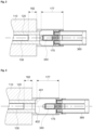
- a connector system 100 is shown. It includes a main body 110 with a coaxial conductor structure and an arcing space. It is contacted by a source connector 200 and a removable load connector 300, which may be disconnected while power is provided at the source connector and/or power is provided at the load connector.
- the connector system includes a main body 110 holding an insulating tube 120.
- the main body 110 may include an electrically conductive material, like a metal which may be copper, brass, or aluminum. It may further be coated or galvanized by a highly conductive material e.g., silver, gold, or an alloy including one of these.
- the insulating tube may include a dielectric material which is suitable for radio frequencies. This may for example be PTFE.
- the insulating tube includes a heat resistant dielectric material like polyimide which can withstand higher temperatures which are generated by arcs during connecting and/or disconnecting of the connector system.
- Within the insulating tube 120 is a main center conductor 130.
- the main center conductor 130 may include a solid cylinder of a material or metal, which may provide a comparatively high thermal capacity to absorb heat which is developed by arcs. It may further have a certain minimum length to provide a larger outer surface area which allows to dissipate heat through the insulating tube 120 to the main body 110 which may be of a thermally conductive material.
- the main center conductor 130 may be held in place by a dielectric support 134.
- the main center conductor has a main contact area 132 at one end.
- This main contact area 132 may include or may be coated with a specific heat-resistant and/or arc-resistant material. Such a material may e.g., be tungsten or a silver alloy further including e.g., nickel and/or cadmium.
- the main contact area may be a planar surface, or it may be a surface with a large radius of 10 cm or more.
- the main contact area 132 is recessed within the insulating tube 120 at a distance 182 to form an arcing space 180 within the insulating tube 120. Within this arcing space, arcs may develop when opening or closing the electrical contact when RF-power is applied to the connector system.
- This arcing space 180 is within the insulating tube such that no arc may develop from a center conductor to an outer conductor due to hot ionized gases.
- the main contact area 132 is contacted by a center contact pin 340 which may be part of the load connector 340.
- This pin 340 may have a pin body 342 which may be held by a guide sleeve 346 and further has a center contact area 344 at its tip, which is configured to contact the main contact area 132.
- a spring 348 may be provided which may press the center contact pin 340 against the main center conductor 130.
- the center contact pin 340 may also include a heat-resistant and/or arc-resistant material.
- the center contact pin 340 may have a depth stop or limit stop 349, such that it may only extend a few millimeters from the guide sleeve 346, which may be sufficient for providing an electrical contact when properly inserted into the insulating tube.
- the depth stop may prevent a long arc when disconnecting the connectors due to a long extension of the center contact pin.
- the center contact pin may have a cylindrical shape or outer contour, such that any air gap to the insulating tube may be reduced or eliminated, such that partial discharges are minimized, and the lifetime is significantly increased.
- the load connector 300 may include a center conductor 350, which may contact the center contact pin 340. It may further include an outer conductor 360 spaced from the center conductor 350 by a spacing tube 364.
- the outer conductor 360 may have an outer conductor connector 362 which may include a plurality of contact springs to contact a contact sleeve 175.
- the outer conductor may include a spacer 366 which may be a ring of an insulating material, e.g., a plastic material which may easily slide along the contact sleeve 175.
- the contact sleeve 175 may be one part with the main body 110 or it may be attached to the main body 110, e.g., by an outer flange 170.
- the outer flange 170 may be screwed to the main body by screws 190.
- the contact sleeve 175 may be configured to contact the outer conductor 360 of the load connector 300 when the center contact pin 340 protrudes at least partially into the insulating tube 120. Further, the contact sleeve 175 may have an inner length 177 which is larger than the recess distance 182.
- a source connector 200 may include an inner conductor 210 and an outer conductor 220. There may be an inner connector contact 230.
- the outer conductor 220 may be extended in its length as shown or longer. In the case, the source connector 200 is disconnected and power is fed from the load connector 300 (in reverse direction), this may be radiated by a normal RF connector as source connector. Such radiation og high power may be harmful to persons handling the device.
- the extended length outer conductor acts as a circular waveguide, in which TEM waves coming from the load connector cannot propagate and therefore blocks or at least significantly reduces reverse RF power from the load connector.
- the source connector outer conductor (220) may exceed in its lenght the source connector inner conductor (210) preferably of at least one half or one wavelength of a signal transmitted. This solution may also be used alone, without the connector system 100, but significantly reduces the safety of the connector system 100, when combined with it.
- the inner length 177 of the contact sleeve 175 may be larger than the recess distance 182.
- the inner length 177 is the length, which may be used to establish a contact between the outer conductor 360 and the contact sleeve 175. This relationship of lengths may ensure, that the outer conductor 360 is in contact with the contact sleeve 175 before it enters the insulating tube 120.
- FIG. 3 shows arcing paths.
- the shortest arcing path 401 in disconnected or OFF state is from the main center conductor along the insulating tube 120 to the main body or a part thereof outside the insulating tube 120.
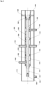
- Figure 4 shows an embodiment having a pneumatic actuator in a side cut view.
- the center contact pin 340 of figure 1 is replaced by a pneumatic piston operated center contact pin 520.
- It may include a pneumatic piston section and a contact pin section which may be a single (monolithic) part or separated parts, e.g., having a contact section 520 and a piston rod section 526.
- the contact pin section may further have a contact element 528, which may include a contact material with low resistive contact properties and/or arc proofness.
- the pneumatic piston operated center contact pin 520 may be held in an essentially coaxial tube forming the center conductor 530.
- An outer conductor 510 is coaxially surrounding the center conductor 530.
- the outer conductor may be slidable in a contact sleeve 175 or fixedly mounted to the main body.
- At least one piston 522, 524 is part of or mounted to the center contact pin 520 and seals against the interior of center conductor 530.
- the pistons can move along a common center axis 580 of the center contact pin 520 and the center conductor 530.
- the pistons are operated by gas pressure provided through first and second gas ducts 542, 543, 544, 545.
- the gas ducts may include dielectric insulating material and may further hold the center conductor 530 within the outer conductor 510.
- the gas may be any type of gas. Air and nitrogen are well suited.
- An inert gas like argon may be used, as this may also help to quench or extinguish any arc at the electrical contact. Such an inert gas may also be provided by an inert gas duct 590.
- the center conductor 530 may be moved to left side in figure 4 by providing gas pressure through the second gas ducts 544, 545, filling first chambers 552, 554 and pressing the pistons 522, 524 to the left.
- the center conductor 530 may be moved to right side in figure 4 by providing gas pressure through the first gas ducts 542, 543, filling second chambers 553, 555 and pressing the pistons 522, 524 to the right.
- the at least one locking lever 562 may snap into a recess or groove in the pneumatic piston operated center contact pin 520, when the contact pin is in a closed position (left side). It may also lock into a second recess or groove in the pneumatic piston operated center contact pin 520, when the contact pin is in an open position (right side).
- the at least one locking lever may include a spring or other elastic element to hold the locking lever in a position engaged with the contact pin.
- the release pin may be operated manually through a flexible outer conductor 510 by pressing on the outer conductor 510.
- Figure 5 shows the previous embodiment in a front view.
Landscapes
- Coupling Device And Connection With Printed Circuit (AREA)
Applications Claiming Priority (1)
| Application Number | Priority Date | Filing Date | Title |
|---|---|---|---|
| EP21191786.9A EP4138226A1 (fr) | 2021-08-17 | 2021-08-17 | Connecteur rf avec suppression d'arc |
Publications (1)
| Publication Number | Publication Date |
|---|---|
| EP4138227A1 true EP4138227A1 (fr) | 2023-02-22 |
Family
ID=77398400
Family Applications (2)
| Application Number | Title | Priority Date | Filing Date |
|---|---|---|---|
| EP21191786.9A Withdrawn EP4138226A1 (fr) | 2021-08-17 | 2021-08-17 | Connecteur rf avec suppression d'arc |
| EP22189062.7A Pending EP4138227A1 (fr) | 2021-08-17 | 2022-08-05 | Connecteur rf avec suppression d'arc |
Family Applications Before (1)
| Application Number | Title | Priority Date | Filing Date |
|---|---|---|---|
| EP21191786.9A Withdrawn EP4138226A1 (fr) | 2021-08-17 | 2021-08-17 | Connecteur rf avec suppression d'arc |
Country Status (2)
| Country | Link |
|---|---|
| EP (2) | EP4138226A1 (fr) |
| CN (1) | CN115911989A (fr) |
Citations (8)
| Publication number | Priority date | Publication date | Assignee | Title |
|---|---|---|---|---|
| DE497612C (de) * | 1930-05-13 | Aeg | Steckvorrichtung mit konzentrisch angeordneten Kontakten | |
| US6139344A (en) * | 1999-03-31 | 2000-10-31 | Wang; Tsan-Chi | Coaxial cable connector with signal path switching arrangement |
| DE10139844C1 (de) * | 2001-08-14 | 2003-04-17 | Fraunhofer Ges Forschung | Elektrischer Steckverbinder mit einem Stecker und einen Gegenstecker |
| US7021964B1 (en) * | 2005-02-08 | 2006-04-04 | Croan Quinn F | RJ “F”, modular connector for coaxial cables |
| US8771012B2 (en) * | 2010-05-20 | 2014-07-08 | Thales | Antenna interface having a socket with two coaxial cables and a mating plug with two piston contactors supported by a flexible membrane |
| EP3300535A1 (fr) | 2016-08-04 | 2018-04-04 | Spinner GmbH | Connecteur rf à faible intermodulation passive |
| CN207782024U (zh) * | 2017-12-22 | 2018-08-28 | 贵州航天电器股份有限公司 | 一种能实现自动脱落的气电混装连接器 |
| EP3474389A1 (fr) * | 2017-10-18 | 2019-04-24 | Vestel Elektronik Sanayi ve Ticaret A.S. | Connecteur femelle pour relier différents connecteurs coaxiaux mâles |
-
2021
- 2021-08-17 EP EP21191786.9A patent/EP4138226A1/fr not_active Withdrawn
-
2022
- 2022-08-05 EP EP22189062.7A patent/EP4138227A1/fr active Pending
- 2022-08-17 CN CN202210986482.7A patent/CN115911989A/zh active Pending
Patent Citations (8)
| Publication number | Priority date | Publication date | Assignee | Title |
|---|---|---|---|---|
| DE497612C (de) * | 1930-05-13 | Aeg | Steckvorrichtung mit konzentrisch angeordneten Kontakten | |
| US6139344A (en) * | 1999-03-31 | 2000-10-31 | Wang; Tsan-Chi | Coaxial cable connector with signal path switching arrangement |
| DE10139844C1 (de) * | 2001-08-14 | 2003-04-17 | Fraunhofer Ges Forschung | Elektrischer Steckverbinder mit einem Stecker und einen Gegenstecker |
| US7021964B1 (en) * | 2005-02-08 | 2006-04-04 | Croan Quinn F | RJ “F”, modular connector for coaxial cables |
| US8771012B2 (en) * | 2010-05-20 | 2014-07-08 | Thales | Antenna interface having a socket with two coaxial cables and a mating plug with two piston contactors supported by a flexible membrane |
| EP3300535A1 (fr) | 2016-08-04 | 2018-04-04 | Spinner GmbH | Connecteur rf à faible intermodulation passive |
| EP3474389A1 (fr) * | 2017-10-18 | 2019-04-24 | Vestel Elektronik Sanayi ve Ticaret A.S. | Connecteur femelle pour relier différents connecteurs coaxiaux mâles |
| CN207782024U (zh) * | 2017-12-22 | 2018-08-28 | 贵州航天电器股份有限公司 | 一种能实现自动脱落的气电混装连接器 |
Also Published As
| Publication number | Publication date |
|---|---|
| CN115911989A (zh) | 2023-04-04 |
| EP4138226A1 (fr) | 2023-02-22 |
Similar Documents
| Publication | Publication Date | Title |
|---|---|---|
| CA2798696C (fr) | Connecteur coaxial a haute frequence | |
| CN103238196B (zh) | 电接触装置 | |
| US5981893A (en) | Electrical switching device | |
| WO1991004122A1 (fr) | Connecteur a debranchement rapide pour appareil a jet de plasma | |
| CN105244231A (zh) | 单刀三掷n型高频率大功率射频同轴继电器 | |
| US9531140B2 (en) | Coaxial protective device | |
| EP1018193B1 (fr) | Connecteur pourvu d'une came solidaire servant a actionner un commutateur | |
| CA1145800A (fr) | Disjoncteur a gaz comprime avec rechauffeur | |
| EP4138227A1 (fr) | Connecteur rf avec suppression d'arc | |
| CN112563793A (zh) | 一种大功率射频同轴连接器 | |
| CN104008921B (zh) | 大功率射频同轴继电器开关 | |
| US6570116B2 (en) | Current carrying assembly for a circuit breaker | |
| US11348748B2 (en) | Switch device | |
| US2472274A (en) | High-frequency coaxial cable switch | |
| CN101233593A (zh) | 电开关装置以及运行电开关装置的方法 | |
| CN101116163B (zh) | 用于气体绝缘高压断路器的开关室 | |
| US5245625A (en) | High-frequency-excited laser for high output powers, particularly a CO.sub.2 | |
| JP7571286B2 (ja) | 真空開閉器 | |
| CN118975044B (zh) | 非接触式高功率射频连接器 | |
| EP4109667A1 (fr) | Connecteur haute puissance rf sans contact | |
| GB2263590A (en) | Connector with impedance-matched switch | |
| CN212810510U (zh) | 一种非接触式短路负载 | |
| EP3930124A1 (fr) | Agencement de dissipation de chaleur pour appareils de commutation | |
| RU202991U1 (ru) | Коаксиальный переключатель большой мощности | |
| US5247267A (en) | Utilizing thermal conductors to increase operating power of coaxial microwave devices |
Legal Events
| Date | Code | Title | Description |
|---|---|---|---|
| PUAI | Public reference made under article 153(3) epc to a published international application that has entered the european phase |
Free format text: ORIGINAL CODE: 0009012 |
|
| STAA | Information on the status of an ep patent application or granted ep patent |
Free format text: STATUS: THE APPLICATION HAS BEEN PUBLISHED |
|
| AK | Designated contracting states |
Kind code of ref document: A1 Designated state(s): AL AT BE BG CH CY CZ DE DK EE ES FI FR GB GR HR HU IE IS IT LI LT LU LV MC MK MT NL NO PL PT RO RS SE SI SK SM TR |
|
| STAA | Information on the status of an ep patent application or granted ep patent |
Free format text: STATUS: REQUEST FOR EXAMINATION WAS MADE |
|
| 17P | Request for examination filed |
Effective date: 20230817 |
|
| RBV | Designated contracting states (corrected) |
Designated state(s): AL AT BE BG CH CY CZ DE DK EE ES FI FR GB GR HR HU IE IS IT LI LT LU LV MC MK MT NL NO PL PT RO RS SE SI SK SM TR |
|
| STAA | Information on the status of an ep patent application or granted ep patent |
Free format text: STATUS: EXAMINATION IS IN PROGRESS |
|
| 17Q | First examination report despatched |
Effective date: 20250228 |