EP4138228A1 - Schnellmontagesteckverbinder - Google Patents
Schnellmontagesteckverbinder Download PDFInfo
- Publication number
- EP4138228A1 EP4138228A1 EP22190510.2A EP22190510A EP4138228A1 EP 4138228 A1 EP4138228 A1 EP 4138228A1 EP 22190510 A EP22190510 A EP 22190510A EP 4138228 A1 EP4138228 A1 EP 4138228A1
- Authority
- EP
- European Patent Office
- Prior art keywords
- legs
- operable
- contact carrier
- section
- flexible
- Prior art date
- Legal status (The legal status is an assumption and is not a legal conclusion. Google has not performed a legal analysis and makes no representation as to the accuracy of the status listed.)
- Pending
Links
Images



Classifications
-
- H—ELECTRICITY
- H01—ELECTRIC ELEMENTS
- H01R—ELECTRICALLY-CONDUCTIVE CONNECTIONS; STRUCTURAL ASSOCIATIONS OF A PLURALITY OF MUTUALLY-INSULATED ELECTRICAL CONNECTING ELEMENTS; COUPLING DEVICES; CURRENT COLLECTORS
- H01R13/00—Details of coupling devices of the kinds covered by groups H01R12/70 or H01R24/00 - H01R33/00
- H01R13/58—Means for relieving strain on wire connection, e.g. cord grip, for avoiding loosening of connections between wires and terminals within a coupling device terminating a cable
- H01R13/582—Means for relieving strain on wire connection, e.g. cord grip, for avoiding loosening of connections between wires and terminals within a coupling device terminating a cable the cable being clamped between assembled parts of the housing
- H01R13/5829—Means for relieving strain on wire connection, e.g. cord grip, for avoiding loosening of connections between wires and terminals within a coupling device terminating a cable the cable being clamped between assembled parts of the housing the clamping part being flexibly or hingedly connected to the housing
-
- H—ELECTRICITY
- H01—ELECTRIC ELEMENTS
- H01R—ELECTRICALLY-CONDUCTIVE CONNECTIONS; STRUCTURAL ASSOCIATIONS OF A PLURALITY OF MUTUALLY-INSULATED ELECTRICAL CONNECTING ELEMENTS; COUPLING DEVICES; CURRENT COLLECTORS
- H01R13/00—Details of coupling devices of the kinds covered by groups H01R12/70 or H01R24/00 - H01R33/00
- H01R13/62—Means for facilitating engagement or disengagement of coupling parts or for holding them in engagement
- H01R13/639—Additional means for holding or locking coupling parts together, after engagement, e.g. separate keylock, retainer strap
-
- H—ELECTRICITY
- H01—ELECTRIC ELEMENTS
- H01R—ELECTRICALLY-CONDUCTIVE CONNECTIONS; STRUCTURAL ASSOCIATIONS OF A PLURALITY OF MUTUALLY-INSULATED ELECTRICAL CONNECTING ELEMENTS; COUPLING DEVICES; CURRENT COLLECTORS
- H01R13/00—Details of coupling devices of the kinds covered by groups H01R12/70 or H01R24/00 - H01R33/00
- H01R13/46—Bases; Cases
- H01R13/502—Bases; Cases composed of different pieces
- H01R13/506—Bases; Cases composed of different pieces assembled by snap action of the parts
-
- H—ELECTRICITY
- H01—ELECTRIC ELEMENTS
- H01R—ELECTRICALLY-CONDUCTIVE CONNECTIONS; STRUCTURAL ASSOCIATIONS OF A PLURALITY OF MUTUALLY-INSULATED ELECTRICAL CONNECTING ELEMENTS; COUPLING DEVICES; CURRENT COLLECTORS
- H01R13/00—Details of coupling devices of the kinds covered by groups H01R12/70 or H01R24/00 - H01R33/00
- H01R13/46—Bases; Cases
- H01R13/52—Dustproof, splashproof, drip-proof, waterproof, or flameproof cases
- H01R13/5205—Sealing means between cable and housing, e.g. grommet
-
- H—ELECTRICITY
- H01—ELECTRIC ELEMENTS
- H01R—ELECTRICALLY-CONDUCTIVE CONNECTIONS; STRUCTURAL ASSOCIATIONS OF A PLURALITY OF MUTUALLY-INSULATED ELECTRICAL CONNECTING ELEMENTS; COUPLING DEVICES; CURRENT COLLECTORS
- H01R13/00—Details of coupling devices of the kinds covered by groups H01R12/70 or H01R24/00 - H01R33/00
- H01R13/62—Means for facilitating engagement or disengagement of coupling parts or for holding them in engagement
- H01R13/629—Additional means for facilitating engagement or disengagement of coupling parts, e.g. aligning or guiding means, levers, gas pressure electrical locking indicators, manufacturing tolerances
-
- H—ELECTRICITY
- H01—ELECTRIC ELEMENTS
- H01R—ELECTRICALLY-CONDUCTIVE CONNECTIONS; STRUCTURAL ASSOCIATIONS OF A PLURALITY OF MUTUALLY-INSULATED ELECTRICAL CONNECTING ELEMENTS; COUPLING DEVICES; CURRENT COLLECTORS
- H01R2201/00—Connectors or connections adapted for particular applications
- H01R2201/26—Connectors or connections adapted for particular applications for vehicles
Definitions
- the disclosure relates generally to the field of plug connectors and, more particularly, to a quick-assembly plug connector.
- Electronic braking systems conforming to ISO/DIN 7638, electrical connection of equipment and running gear conforming to ISO 12098, and electrical connection of electronically monitored charging systems conforming to ISO 25981, are all requirements on vehicles weighing over a certain weight limit (e.g., 3.5 tons).
- these systems include connectors used for the electrical connection between a truck and a trailer/semitrailer, both for 24V and 12V electrical systems.
- the connectors are available in 5, 7, or 15 pole versions, and may be equipped with stainless steel locking lever and rollers to prevent accidental disconnection.
- current connectors are overly complex, leading to increased part costs and assembly time.
- an assembly may include a body, and a contact carrier within the body, the contact carrier including a main body including a plurality of openings each operable to receive a contact, and a plurality of legs extending from the main body, each of the plurality of legs coupled with the body.
- a plug connector may include a body including a first end, a second end, and an interior cavity.
- the plug connector may further include a contact carrier within the interior cavity of the body, the contact carrier including a main body including a plurality of openings each operable to receive a contact, and a plurality of legs extending from the main body, each of the plurality of legs coupled with the body.
- a plug connector may include a body having a first end, a second end, and an interior cavity, and a contact carrier within the interior cavity of the body.
- the contact carrier may include a main body including a plurality of openings each operable to receive a contact, and a plurality of legs extending from the main body.
- Each of the plurality of legs may be coupled with the body, wherein the plurality of legs are configurable between an open position wherein a central support of the plurality of legs is disengaged from a cable connected with the contact, and a closed position wherein the central support of the plurality of legs is engaged with the cable.
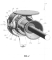
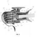
- FIGs. 1-3 illustrate a plug connector (hereinafter "connector") 100 according to embodiments of the present disclosure.
- the connector 100 may include a body 102 and a contact carrier 104 within an internal cavity 103 of the body 102.
- the contact carrier 104 may include a main body 108 including a plurality of openings 110 each operable to receive an electrical contact 112.
- the contacts 112 may be connected to a cable 114 by a series of connections (e.g., wires or leads) 116 ( FIG. 3 ).
- the connections 116 may be fixed to the contacts 112 by contact screws or by crimping.
- the body 102 may include a first section 118 at a distal end 123 and a second section 120 at a proximal end 125.
- the first section 118 may define a first portion of the internal cavity 103, wherein the first portion is operable to receive the main body 108 of the contact carrier 104 and the contacts 112.
- the second section 120 of the body 102 may extend from the first section 118, the second section 120 defining a second portion of the internal cavity 103.
- the second section 120 may take on a bell or trumpet-shape configuration.
- the body 102 may be made from one or more non-conductive materials.
- the second section 120 may include a gasket 122 within the second portion of the internal cavity 103.
- the gasket 122 is operable to surround and protect the cable 114.
- the gasket 122 may include a first portion 126 adjacent to, or in abutment with, a central support 128 of the contact carrier 104.
- the gasket 122 may include a second portion 130 connected with the first portion 126, wherein the second portion 130 may extend within the internal cavity 103 of the second section 120 of the body 102.
- the first portion 126 of the gasket 122 may form a seal against an interior surface 134 of the body 102 adjacent the central support 128, and the second portion 130 of the gasket 122 may form a seal against a second interior surface 136 of the second section 120 of the body 102.
- the gasket 122 may further include a recess operable to engage a ridge or flange 132 along the interior surface 134 of the body 102 to maintain positioning of the gasket 122 within the body 102.
- the connector 100 may include a locking device 138 coupled to the body 102.
- the locking device 138 may include one or more rollers 140 adjacent the first section 118 of the body 102, wherein the rollers 140 may be pushed through an opening of a first arm 141.
- Each roller 140 may have a central area with a reduced diameter to accommodate the first arm 141.
- the first arm 141 and the opening through the first arm 141 may be bent or stretched to receive the roller 140.
- the rollers 140 ensure mechanical engagement between the locking device 138 and a socket (not shown).
- the present embodiments include just two rollers and a single locking device, which simplifies assembly and reduces overall cost.
- a second arm 142 of the locking device 138 may include an opening 143 operable to receive a snap-fit joint 144 along an exterior 145 of the body 102.
- the snap-fit joint 144 may include one or more flexible arms or tabs 147 operable to engage a flange 146 surrounding the opening 143 to maintain a connection between the second arm 142 and the body 102.
- the connector 100 may include a sealing ring 149 mounted around the first section 118 of the body 102 to create a seal between the body 102 and a second coupled connector body (not shown).
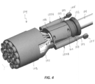
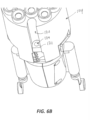
- the contact carrier 104 may include first and second legs 150A, 150B extending from the main body 108.
- Each of the first and second legs 150A, 150B may be include a base 152 connected to, or integrally formed with, the main body 108, and a free end 153 opposite the base 152.
- the free end 153 may include a depressible tab or button 155, which extends through an opening 154 ( FIG. 1 ) of the second section 120 of the body 102.
- the buttons 155 may permit the contact carrier 104 to be conveniently released from the body 102.
- the free ends 153 may include a sealing ring 157 operable to prevent moisture from entering the internal cavity 103 via the opening 154 of the body 102.
- the contact carrier 104 may include the central support 128 surrounding the cable 114.
- the central support 128 may include a first component 158 coupled with a second component 160.
- the first and second components 158, 160 may define a central cavity operable to receive and lock the cable 114 therein.
- the first and second components 158, 160 may be located between the base 152 and the free ends 153 of the first and second legs 150A-150B, respectively.
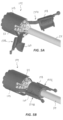
- the first and second components 158, 160 may move between an open position ( FIG. 5A ), in which the first and second components 158, 160 are disengaged from one another and rotated/bent away from the cable 114, and a closed position ( FIG. 5B ), in which the first and second components 158, 160 are brought towards one another and coupled together, e.g., by one or more fasteners.
- This configuration allows easier and quicker assembly/disassembly between the contact carrier 104 and the contacts 112.
- the body 102 may include a snap-fit joint or device 164 within the internal cavity 103 of the first section 118 of the body 102.
- the snap-fit device 164 may be a circular snap-fit joint including a plurality of flexible arms or tabs 166 separated from one another by one or more gaps.
- the flexible tabs 166 may extend from a base 168 extending into the internal cavity 103 from the interior 134 of the body 102.
- the contact carrier 104 may include a channel 170 and a retaining wall 172 extending across the channel 170.
- the retaining wall 172 may include an opening 174 operable to receive the flexible tabs 166 of the snap-fit device 164. With the snap-fit device 164 engaged with the retaining wall 172, mechanical retention of the contact carrier 104 within the body 102 is improved.
- each of the expressions “at least one of A, B and C”, “at least one of A, B, or C”, “one or more of A, B, and C", “one or more of A, B, or C" and "A, B, and/or C” means A alone, B alone, C alone, A and B together, A and C together, B and C together, or A, B and C together.
- All directional references e.g., proximal, distal, upper, lower, upward, downward, left, right, lateral, longitudinal, front, back, top, bottom, above, below, vertical, horizontal, radial, axial, clockwise, and counterclockwise
- Connection references e.g., attached, coupled, connected, and joined
- connection references are to be construed broadly and may include intermediate members between a collection of elements and relative movement between elements unless otherwise indicated. As such, connection references do not necessarily infer that two elements are directly connected and in fixed relation to each other.
- identification references e.g., primary, secondary, first, second, third, fourth, etc. are not intended to connote importance or priority, but are used to distinguish one feature from another.
- the drawings are for purposes of illustration only and the dimensions, positions, order and relative sizes reflected in the drawings attached hereto may vary.
- the terms “substantial” or “substantially,” as well as the terms “approximate” or “approximately,” can be used interchangeably in some embodiments, and can be described using any relative measures acceptable by one of ordinary skill in the art. For example, these terms can serve as a comparison to a reference parameter, to indicate a deviation capable of providing the intended function. Although non-limiting, the deviation from the reference parameter can be, for example, in an amount of less than 1%, less than 3%, less than 5%, less than 10%, less than 15%, less than 20%, and so on.
Landscapes
- Connector Housings Or Holding Contact Members (AREA)
Applications Claiming Priority (1)
| Application Number | Priority Date | Filing Date | Title |
|---|---|---|---|
| US17/404,196 US11677186B2 (en) | 2021-08-17 | 2021-08-17 | Quick assembly plug connector |
Publications (1)
| Publication Number | Publication Date |
|---|---|
| EP4138228A1 true EP4138228A1 (de) | 2023-02-22 |
Family
ID=82940035
Family Applications (1)
| Application Number | Title | Priority Date | Filing Date |
|---|---|---|---|
| EP22190510.2A Pending EP4138228A1 (de) | 2021-08-17 | 2022-08-16 | Schnellmontagesteckverbinder |
Country Status (3)
| Country | Link |
|---|---|
| US (1) | US11677186B2 (de) |
| EP (1) | EP4138228A1 (de) |
| CN (1) | CN115939827A (de) |
Citations (5)
| Publication number | Priority date | Publication date | Assignee | Title |
|---|---|---|---|---|
| US4713023A (en) * | 1987-01-30 | 1987-12-15 | Molex Incorporated | Electrical connector and method of assembly |
| US20140305700A1 (en) * | 2011-06-21 | 2014-10-16 | Adc Telecommunications, Inc. | Connector with slideable retention feature and patch cord having the same |
| US10109961B1 (en) * | 2017-10-12 | 2018-10-23 | Chia-Hua Lin | Plug structure |
| CN109643867A (zh) * | 2016-07-15 | 2019-04-16 | 赫斯曼汽车有限公司 | 用于内燃机的爆震传感器的耐高温的插接连接器 |
| US20210242623A1 (en) * | 2020-02-05 | 2021-08-05 | Panduit Corp. | Modular communications plug |
Family Cites Families (7)
| Publication number | Priority date | Publication date | Assignee | Title |
|---|---|---|---|---|
| US4062616A (en) * | 1976-08-19 | 1977-12-13 | Amp Incorporated | Flat flexible cable connector assembly including insulation piercing contacts |
| US5895291A (en) * | 1995-11-02 | 1999-04-20 | The Whitaker Corporation | Shielded cable connector assembly |
| US6932641B1 (en) * | 2004-02-20 | 2005-08-23 | Sheng Hsin Liao | Plug structure |
| US20090215306A1 (en) * | 2006-05-26 | 2009-08-27 | Centerpin Technology, Inc. | Electrical connector with compression gores |
| DE102007009947B4 (de) * | 2007-03-01 | 2016-11-24 | Techpointe S.A. | Steckerelement |
| US8545257B2 (en) * | 2011-09-20 | 2013-10-01 | Jason Pedruzzi | Integrated banding connector |
| JP6757611B2 (ja) * | 2016-07-20 | 2020-09-23 | ヒロセ電機株式会社 | 端子支持体を有する電気コネクタ |
-
2021
- 2021-08-17 US US17/404,196 patent/US11677186B2/en active Active
-
2022
- 2022-08-16 CN CN202210980001.1A patent/CN115939827A/zh active Pending
- 2022-08-16 EP EP22190510.2A patent/EP4138228A1/de active Pending
Patent Citations (5)
| Publication number | Priority date | Publication date | Assignee | Title |
|---|---|---|---|---|
| US4713023A (en) * | 1987-01-30 | 1987-12-15 | Molex Incorporated | Electrical connector and method of assembly |
| US20140305700A1 (en) * | 2011-06-21 | 2014-10-16 | Adc Telecommunications, Inc. | Connector with slideable retention feature and patch cord having the same |
| CN109643867A (zh) * | 2016-07-15 | 2019-04-16 | 赫斯曼汽车有限公司 | 用于内燃机的爆震传感器的耐高温的插接连接器 |
| US10109961B1 (en) * | 2017-10-12 | 2018-10-23 | Chia-Hua Lin | Plug structure |
| US20210242623A1 (en) * | 2020-02-05 | 2021-08-05 | Panduit Corp. | Modular communications plug |
Also Published As
| Publication number | Publication date |
|---|---|
| CN115939827A (zh) | 2023-04-07 |
| US11677186B2 (en) | 2023-06-13 |
| US20230056598A1 (en) | 2023-02-23 |
Similar Documents
| Publication | Publication Date | Title |
|---|---|---|
| US8376778B2 (en) | Connector with resilient retainer for contact | |
| US5989052A (en) | Electrical outlet safety cover and cord connector | |
| US7950944B1 (en) | Electrical connector having a locking collar | |
| EP3148012A1 (de) | Verbinder | |
| US7731536B2 (en) | Shielded connector | |
| US9385516B2 (en) | Connector | |
| US8747157B2 (en) | Connector | |
| US7731543B2 (en) | Shielded connector | |
| EP2081259B1 (de) | Steckverbinder | |
| US9673563B2 (en) | Connector | |
| US9153894B2 (en) | Terminal position assurance with dual primary lock reinforcement and independent secondary lock | |
| US9680247B1 (en) | Round terminal with low profile cap | |
| CN107453158B (zh) | 一种线束连接器及一种线缆连接方法 | |
| US20120064751A1 (en) | Electrical Connector Assembly | |
| US9887486B2 (en) | Connector | |
| US9595784B2 (en) | Connector | |
| EP2390963B1 (de) | Verbinder, Verbindereinheit und Verfahren zur Herstellung eines Verbinders | |
| US2700144A (en) | Electrical socket assembly | |
| US20200176916A1 (en) | Power connector device including improved terminal | |
| EP4138228A1 (de) | Schnellmontagesteckverbinder | |
| JP6314908B2 (ja) | ゴム栓付きカバーユニット及びコネクタ | |
| CN114389109B (zh) | 一种可转动的插头配合结构 | |
| US9698517B2 (en) | Connector with a wire cover having an opening for arranging wires pulled out from a housing of the connector | |
| EP0074159B1 (de) | Schutzhaube für eine schnellösbare elektrische Verbindung | |
| US11710921B2 (en) | Connector with metal spring |
Legal Events
| Date | Code | Title | Description |
|---|---|---|---|
| PUAI | Public reference made under article 153(3) epc to a published international application that has entered the european phase |
Free format text: ORIGINAL CODE: 0009012 |
|
| STAA | Information on the status of an ep patent application or granted ep patent |
Free format text: STATUS: THE APPLICATION HAS BEEN PUBLISHED |
|
| AK | Designated contracting states |
Kind code of ref document: A1 Designated state(s): AL AT BE BG CH CY CZ DE DK EE ES FI FR GB GR HR HU IE IS IT LI LT LU LV MC MK MT NL NO PL PT RO RS SE SI SK SM TR |
|
| STAA | Information on the status of an ep patent application or granted ep patent |
Free format text: STATUS: REQUEST FOR EXAMINATION WAS MADE |
|
| 17P | Request for examination filed |
Effective date: 20230818 |
|
| RBV | Designated contracting states (corrected) |
Designated state(s): AL AT BE BG CH CY CZ DE DK EE ES FI FR GB GR HR HU IE IS IT LI LT LU LV MC MK MT NL NO PL PT RO RS SE SI SK SM TR |
|
| STAA | Information on the status of an ep patent application or granted ep patent |
Free format text: STATUS: EXAMINATION IS IN PROGRESS |
|
| 17Q | First examination report despatched |
Effective date: 20250114 |
|
| GRAP | Despatch of communication of intention to grant a patent |
Free format text: ORIGINAL CODE: EPIDOSNIGR1 |
|
| STAA | Information on the status of an ep patent application or granted ep patent |
Free format text: STATUS: GRANT OF PATENT IS INTENDED |
|
| INTG | Intention to grant announced |
Effective date: 20260316 |