EP4138384A2 - Appareil d'imagerie, procédé d'imagerie et support de stockage - Google Patents
Appareil d'imagerie, procédé d'imagerie et support de stockage Download PDFInfo
- Publication number
- EP4138384A2 EP4138384A2 EP22185849.1A EP22185849A EP4138384A2 EP 4138384 A2 EP4138384 A2 EP 4138384A2 EP 22185849 A EP22185849 A EP 22185849A EP 4138384 A2 EP4138384 A2 EP 4138384A2
- Authority
- EP
- European Patent Office
- Prior art keywords
- images
- imaging
- imaging apparatus
- exposure
- image
- Prior art date
- Legal status (The legal status is an assumption and is not a legal conclusion. Google has not performed a legal analysis and makes no representation as to the accuracy of the status listed.)
- Pending
Links
- 238000003384 imaging method Methods 0.000 title claims abstract description 108
- 238000000034 method Methods 0.000 claims description 9
- 230000035945 sensitivity Effects 0.000 claims description 4
- 230000009466 transformation Effects 0.000 description 13
- 238000010586 diagram Methods 0.000 description 10
- 230000006870 function Effects 0.000 description 8
- 230000003287 optical effect Effects 0.000 description 8
- 230000009467 reduction Effects 0.000 description 8
- 230000014509 gene expression Effects 0.000 description 6
- 238000004364 calculation method Methods 0.000 description 5
- 230000008859 change Effects 0.000 description 5
- 230000001186 cumulative effect Effects 0.000 description 5
- 238000004040 coloring Methods 0.000 description 4
- 238000006243 chemical reaction Methods 0.000 description 2
- 238000005401 electroluminescence Methods 0.000 description 2
- 239000011159 matrix material Substances 0.000 description 2
- 238000005375 photometry Methods 0.000 description 2
- PXFBZOLANLWPMH-UHFFFAOYSA-N 16-Epiaffinine Natural products C1C(C2=CC=CC=C2N2)=C2C(=O)CC2C(=CC)CN(C)C1C2CO PXFBZOLANLWPMH-UHFFFAOYSA-N 0.000 description 1
- 239000003086 colorant Substances 0.000 description 1
- 230000000295 complement effect Effects 0.000 description 1
- 230000006835 compression Effects 0.000 description 1
- 238000007906 compression Methods 0.000 description 1
- 238000001514 detection method Methods 0.000 description 1
- 238000003708 edge detection Methods 0.000 description 1
- 238000001914 filtration Methods 0.000 description 1
- 238000009499 grossing Methods 0.000 description 1
- 239000004973 liquid crystal related substance Substances 0.000 description 1
- 230000007246 mechanism Effects 0.000 description 1
- 229910044991 metal oxide Inorganic materials 0.000 description 1
- 150000004706 metal oxides Chemical class 0.000 description 1
- 230000008520 organization Effects 0.000 description 1
- 230000004044 response Effects 0.000 description 1
- 239000004065 semiconductor Substances 0.000 description 1
Images





Classifications
-
- H—ELECTRICITY
- H04—ELECTRIC COMMUNICATION TECHNIQUE
- H04N—PICTORIAL COMMUNICATION, e.g. TELEVISION
- H04N23/00—Cameras or camera modules comprising electronic image sensors; Control thereof
- H04N23/60—Control of cameras or camera modules
- H04N23/67—Focus control based on electronic image sensor signals
- H04N23/676—Bracketing for image capture at varying focusing conditions
-
- H—ELECTRICITY
- H04—ELECTRIC COMMUNICATION TECHNIQUE
- H04N—PICTORIAL COMMUNICATION, e.g. TELEVISION
- H04N23/00—Cameras or camera modules comprising electronic image sensors; Control thereof
- H04N23/70—Circuitry for compensating brightness variation in the scene
- H04N23/72—Combination of two or more compensation controls
-
- H—ELECTRICITY
- H04—ELECTRIC COMMUNICATION TECHNIQUE
- H04N—PICTORIAL COMMUNICATION, e.g. TELEVISION
- H04N23/00—Cameras or camera modules comprising electronic image sensors; Control thereof
- H04N23/70—Circuitry for compensating brightness variation in the scene
- H04N23/71—Circuitry for evaluating the brightness variation
-
- H—ELECTRICITY
- H04—ELECTRIC COMMUNICATION TECHNIQUE
- H04N—PICTORIAL COMMUNICATION, e.g. TELEVISION
- H04N23/00—Cameras or camera modules comprising electronic image sensors; Control thereof
- H04N23/70—Circuitry for compensating brightness variation in the scene
- H04N23/73—Circuitry for compensating brightness variation in the scene by influencing the exposure time
-
- H—ELECTRICITY
- H04—ELECTRIC COMMUNICATION TECHNIQUE
- H04N—PICTORIAL COMMUNICATION, e.g. TELEVISION
- H04N23/00—Cameras or camera modules comprising electronic image sensors; Control thereof
- H04N23/70—Circuitry for compensating brightness variation in the scene
- H04N23/74—Circuitry for compensating brightness variation in the scene by influencing the scene brightness using illuminating means
-
- H—ELECTRICITY
- H04—ELECTRIC COMMUNICATION TECHNIQUE
- H04N—PICTORIAL COMMUNICATION, e.g. TELEVISION
- H04N23/00—Cameras or camera modules comprising electronic image sensors; Control thereof
- H04N23/70—Circuitry for compensating brightness variation in the scene
- H04N23/743—Bracketing, i.e. taking a series of images with varying exposure conditions
-
- H—ELECTRICITY
- H04—ELECTRIC COMMUNICATION TECHNIQUE
- H04N—PICTORIAL COMMUNICATION, e.g. TELEVISION
- H04N23/00—Cameras or camera modules comprising electronic image sensors; Control thereof
- H04N23/70—Circuitry for compensating brightness variation in the scene
- H04N23/75—Circuitry for compensating brightness variation in the scene by influencing optical camera components
-
- H—ELECTRICITY
- H04—ELECTRIC COMMUNICATION TECHNIQUE
- H04N—PICTORIAL COMMUNICATION, e.g. TELEVISION
- H04N23/00—Cameras or camera modules comprising electronic image sensors; Control thereof
- H04N23/70—Circuitry for compensating brightness variation in the scene
- H04N23/76—Circuitry for compensating brightness variation in the scene by influencing the image signals
-
- H—ELECTRICITY
- H04—ELECTRIC COMMUNICATION TECHNIQUE
- H04N—PICTORIAL COMMUNICATION, e.g. TELEVISION
- H04N23/00—Cameras or camera modules comprising electronic image sensors; Control thereof
- H04N23/80—Camera processing pipelines; Components thereof
-
- H—ELECTRICITY
- H04—ELECTRIC COMMUNICATION TECHNIQUE
- H04N—PICTORIAL COMMUNICATION, e.g. TELEVISION
- H04N23/00—Cameras or camera modules comprising electronic image sensors; Control thereof
- H04N23/56—Cameras or camera modules comprising electronic image sensors; Control thereof provided with illuminating means
Definitions
- the present invention relates to an imaging apparatus that can perform omnifocal imaging with which the images at a plurality of in-focus positions are captured.
- Omnifocal imaging refers to capturing a plurality of images different in in-focus position at all object distances focusable by an imaging apparatus ( Japanese Patent Application Laid-Open Publication No. H10-290389 ).
- a technique of extracting focused areas from among the images acquired in the omnifocal imaging and combining the images at the focused areas into one image that focuses on the entire imaging area with a depth of field deeper than the depth of field of the original images is called focus stacking.
- omnifocal imaging entails changes in brightness among acquired images due to various factors.
- Japanese Patent Application Laid-Open Publication No. 2020-107956 discusses that changes in brightness of images occur with variation in effective F-number in omnifocal imaging.
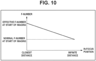
- Fig. 10 illustrates an example of a relationship between in-focus positions and variations in effective F-number in omnifocal imaging.
- Fig. 11 illustrates an example of a relationship between in-focus positions and variations in luminance value in omnifocal imaging. As illustrated in Fig. 10 and Fig. 11 , in omnifocal imaging, the brightness is varied among the images.
- the brightness is varied in omnifocal imaging using a flashlight and in omnifocal imaging using a high-speed shutter.
- Combination of images with differences in brightness can result in a combined image with uneven brightness on it.
- it is suitable to correct variations in brightness of the images to be combined after the images are acquired to get desired brightness.
- a combined image of a scene of which the brightness is corrected to be darker can have a colored high-luminance portion or lack the saturation of luminance on the image.
- Fig. 12 is a diagram illustrating a gamma curve when an RAW image is converted into a YUV image.
- the luminance values of the RAW image along the horizontal axis that exceed a RAW luminance value 1201 are converted into a YUV luminance value 1202, which is the upper limit value.
- the upper limit value of luminance of the YUV image goes down to a YUV luminance value 1204, which makes it impossible to reach the saturation of the luminance value of the YUV image.
- the ratio of the number of red pixels or blue pixels to that of green pixels of the RAW image is varied, which colors the high-luminance portion.
- an omnifocal image of a scene of which the brightness is corrected to be darker can suffer some coloring or differences in the brightness even if variations in brightness are corrected to get a brightness level.
- an imaging apparatus as specified in claims 1 to 17.
- an imaging method as specified in claim 18.
- a computer-readable storage medium as specified in claim 19.
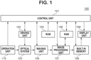
- Fig. 1 is a block diagram illustrating a configuration of a digital camera as an image processing apparatus according to a first embodiment.
- a digital camera 100 can capture a plurality of still images while changing the focus position.
- a control unit 101 is a signal processor such as a central processing unit (CPU) and a microprocessor unit (MPU).
- the control unit 101 controls units of the digital camera 100 while reading programs previously stored in a read only memory (ROM) 105 described below.
- ROM read only memory
- the control unit 101 issues commands to start and end imaging to an imaging unit 104 described below.
- the control unit 101 issues an image processing command to an image processing unit 107 described below based on a program stored in the ROM 105. Commands from a user are input to the digital camera 100 through an operation unit 110 described below, and go to individual units of the digital camera 100 through the control unit 101.
- a driving unit 102 includes a motor, and mechanically operates an optical system 103 described below under the control of the control unit 101.
- the driving unit 102 moves the position of a focus lens included in the optical system 103 to adjust the focal length of the optical system 103 under the control of the control unit 101.
- the optical system 103 includes a zoom lens, the focus lens, and a diaphragm.
- the diaphragm is a mechanism adjusting the quantity of light that passes through the diaphragm.
- the focus position can be changed by changing positions of lenses.
- the imaging unit 104 includes a photoelectric conversion device that performs photoelectric conversion to convert an incident light signal into an electric signal.
- a charge coupled device (CCD) sensor or a complementary metal-oxide semiconductor (CMOS) sensor is applicable to the imaging unit 104.
- the imaging unit 104 supports a moving image mode, and can capture a plurality of temporarily continuous images as frames of a moving image.
- the ROM 105 is a read-only nonvolatile memory as a recording medium, and stores parameters for operation of the individual blocks provided in the digital camera 100, in addition to operation programs for the individual blocks.
- the RAM 106 is a rewritable nonvolatile memory, and is used as an area that temporarily stores data output in the operation of the individual blocks provided in the digital camera 100.
- the image processing unit 107 performs various types of image processing such as white balance adjustment, color interpolation, and filtering on an image output from the imaging unit 104 or data on an image signal recorded in a built-in memory 109 described below.
- image processing unit 107 performs compression processing on data on an image signal captured by the imaging unit 104 in compliance with standards such as Joint Photographic Experts Group (JPEG).
- JPEG Joint Photographic Experts Group
- the image processing unit 107 includes an integrated circuit (application specific integrated circuits (ASIC)) integrally including circuits each performing specific processing.
- the control unit 101 may also carry out a part or all of the functions of the image processing unit 107 by performing processing based on a program read out from the ROM 105. If the control unit 101 performs all of the functions of the image processing unit 107, the image processing unit 107 as hardware is not used.
- ASIC application specific integrated circuits
- a display unit 108 is a liquid crystal display, an organic electroluminescence (EL) display, or another type of display to display an image temporarily stored in the RAM 106, an image stored in the built-in memory 109 described below, and a setting screen of the digital camera 100 by way of example.
- EL organic electroluminescence
- the built-in memory 109 stores images captured by the imaging unit 104, the images processed by the image processing unit 107, information on focus position at imaging, and other types of data.
- a memory card may be used.
- the operation unit 110 includes buttons, switches, keys, and a mode dial provided on the digital camera 100, and a touch panel also used as the display unit 108. Commands from the user go to the control unit 101 through the operation unit 110.
- Fig. 2 is a flowchart illustrating the generation of a combined image according to the present embodiment.
- step S201 the imaging unit 104 captures a plurality of images different in in-focus position.
- the imaging unit 104 performs imaging by changing the in-focus position from the close distance side to the infinite distance side.
- step S202 the control unit 101 and the image processing unit 107 correct the brightness of the plurality of images captured by the imaging unit 104 in step S201.
- step S203 the control unit 101 and the image processing unit 107 align the plurality of images corrected in brightness in step S202.
- step S204 the control unit 101 and the image processing unit 107 combine the images aligned in step S203, thereby generating a combined image.
- the control unit 101 and the image processing unit 107 combine the images aligned in step S203, thereby generating a combined image.
- Fig. 3 is a flowchart illustrating the imaging in step S201 according to the present embodiment.
- step S301 the control unit 101 sets the in-focus position.
- the user designates a focus position through the touch panel also used as the display unit 108, and designates a plurality of in-focus positions with equal intervals in front of and behind the in-focus position corresponding to the designated focus position in the optical axis direction.
- the control unit 101 determines the order of imaging at the set in-focus positions in order of distance.
- step S302 the control unit 101 determines the exposure condition of the imaging.
- the control unit 101 determines the shutter speed, the F-number, and the International Organization for Standardization (ISO) sensitivity.
- the user may manually set the exposure condition, or the control unit 101 may automatically set the exposure condition by causing the imaging unit 104 to perform photometry of the object.
- ISO International Organization for Standardization
- step S303 the control unit 101 calculates the quantity of exposure that corresponds to a darker condition (amount of reduction of exposure) than the exposure condition (predetermined value of exposure) determined in step S301.
- the amount of reduction of exposure is determined based on the performance of the lenses attached in the optical system 103. As the amount of variation in the effective F-number with the change of the in-focus position depends on the lens performance, the amount of variation in the effective F-number as the in-focus position is moved from the closest distance side to the infinite distance side may be handled as the amount of reduction of exposure by way of example. Further, when a flashlight is used, it is suitable that the amount of reduction of exposure is determined in consideration of the characteristic of the flashlight including uneven light emission. When a high-speed shutter is used, it is suitable that the amount of reduction of exposure is determined in consideration of the characteristic of the shutter including uneven exposure. Further, as the amount of reduction of exposure, the shutter speed, the F-number, or the ISO sensitivity may be used.
- step S304 the control unit 101 moves focus to an in-focus position that has not undergone imaging among the in-focus positions set in step S301, based on the order of imaging determined in step S301.
- step S305 the imaging unit 104 performs imaging with an exposure reduced by the amount of reduction of exposure determined in step S303 from the exposure determined in step S302.
- step S306 the control unit 101 determines whether the imaging has been performed at all of the in-focus positions set in step S301. If the imaging has been performed at all of the in-focus positions (YES in step S306), the processing in the flowchart ends. If any in-focus position at which the imaging is to be made is left (NO in step S306), the processing returns to step S304.
- control unit 101 does not change any imaging setting including the exposure other than the in-focus position while the imaging unit 104 captures a plurality of images.
- a mere change in in-focus position will cause the brightness of the image to be changed as described above.
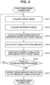
- Fig. 4 is a flowchart illustrating the brightness correction in step S202 according to the present embodiment.
- step S401 the control unit 101 acquires a brightness correction target image from among the images captured by the imaging unit 104 in step S201.
- the brightness correction target image is an image captured earliest in the order of imaging of the images that are not yet targeted for the brightness correction, other than the image captured first.
- step S402 the control unit 101 acquires a brightness correction reference image from among the images captured by the imaging unit 104 in step S201.
- the brightness correction reference image is an image captured before the target image is captured.
- the control unit 101 calculates a brightness ratio of the reference image to the target image.
- the brightness ratio is determined through comparison of the integral value of green pixels of the RAW image of the reference image with the integral value of green pixels of the RAW image of the target image; however, the comparison may be performed using the YUV images or the RGB images, or based on the amount of photometric at the imaging.
- step S404 the control unit 101 calculates the amount of cumulative gain obtained by cumulating the brightness ratios determined in step S403.
- the amount of cumulative gain is determined by multiplying the amount of gain determined before the current reference image and the current target image by the ratio determined in current step S403, in order to bring the brightness of the target image close to the exposure determined in step S302.
- step S405 the control unit 101 associates the amount of cumulative gain determined in step S404 with the target image. It is suitable that the combination of the amount of cumulative gain and the target image is stored in an array form in the RAM 106.
- step S406 the control unit 101 determines whether all of the images have been processed. If all of the images have been processed (YES in step S406), the processing proceeds to step S407. Otherwise (NO in step S406), the processing returns to step S401.
- step S407 the image processing unit 107 performs the brightness correction by the amount of cumulative gain associated in step S405 uniform over an image plane, on all of the images other than the image captured first.
- Brightness correction may be performed on RAW images after sensor output, may be performed when the RAW image is converted into the YUV image, or may be performed on RGB images.
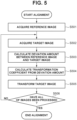
- Fig. 5 is a flowchart illustrating the alignment in step S203 according to the present embodiment.
- step S501 the control unit 101 acquires an alignment reference image from among the images captured by the imaging unit 104 in step S201.
- the alignment reference image is an image captured earliest in the order of imaging.
- the alignment reference image may be an image with the narrowest angle of field of the captured images because the angle of field is slightly varied among the images captured while the in-focus position is changed.
- step S502 the control unit 101 acquires an alignment processing target image.
- the target image is an image yet to be subjected to the alignment processing of the images other than the reference image acquired in step S501. If the image earliest in the order of imaging is used as the reference image, the control unit 101 sequentially acquires the target image in the order of imaging.
- step S503 the control unit 101 calculates the amount of positional deviation between the reference image and the target image.
- An example of a calculation method is as follows. The control unit 101 first sets a plurality of blocks in the reference image. It is suitable that the set blocks have a common size. Next, the control unit 101 sets search ranges on the target image at the positions the same as those of the blocks on the reference image, the search ranges of which each are wider than the corresponding block of the blocks of the reference image. Finally, the control unit 101 calculates a corresponding point at which the sum of absolute difference (SAD) of luminance from that of the corresponding block of the reference image is minimum, for each of the search ranges of the target image.
- SAD sum of absolute difference
- the control unit 101 calculates positional deviation in step S503 in a vector based on the center of each of the blocks of the reference image and the above-described corresponding point. To calculate the above-described correction point, the control unit 101 may use the sum of squared difference (SSD) or a normalized cross correlation (NCC), besides the SAD.
- SSD squared difference
- NCC normalized cross correlation
- step S504 the control unit 101 calculates a transformation coefficient based on the amount of positional deviation between the reference image and the target image.
- the control unit 101 uses a projective transformation coefficient as the transformation coefficient by way of example.
- the transformation coefficient is not limited to the projective transformation coefficient.
- An affine transformation coefficient or a simplified transformation coefficient including horizontal/vertical shift alone may be used.
- step S505 the image processing unit 107 performs transformation on the target image using he transformation coefficient calculated in step S504.
- control unit 101 can perform the transformation using an expression (1).
- (x', y') represents coordinates after the transformation
- (x, y) represents coordinates before the transformation
- a matrix A represents the transformation coefficient calculated by the control unit 101 in step S404.
- step S506 the control unit 101 determines whether the alignment has been performed on all of the images other than the reference image. If the alignment has been performed on all of the images other than the reference image (YES in step S506), the processing of the flowchart illustrated in Fig. 5 ends. If any image to be subjected to the alignment is left (NO in step S506), the processing returns to step S502.
- the amount of parallax generated by positional difference of the optical system 103 can be determined through the calculation of the amount of positional deviation in step S503.
- the alignment can be made by similar processing.
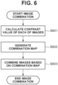
- Fig. 6 is a flowchart illustrating the image combination in step S204 according to the present embodiment.
- step S601 the image processing unit 107 calculates the contrast value of each of the images subjected to the alignment (including reference image).
- the image processing unit 107 first calculates a luminance Y by using the following expression (2) from color signals Sr, Sg, and Sb of each pixel.
- Y 0.299 Sr + 0.587 Sg + 0.114 Sb
- a contrast value I is calculated by applying a Sobel filter to a 3 ⁇ 3 pixel matrix L of the luminance Y as represented by the following expressions (3) to (5).
- I h ⁇ 1 0 1 ⁇ 2 0 2 ⁇ 1 0 1 ⁇ L
- I v ⁇ 1 ⁇ 2 ⁇ 1 0 0 0 1 2 1 ⁇ L
- I I h 2 + I v 2
- an edge detection filter such as a Laplacian filter, or a band pass filter that allows a predetermined frequency band to pass through may also be used.
- step S602 the image processing unit 107 generates a combination map.
- the image processing unit 107 compares the contrast values of the pixels at the same position among the images, and calculates the combination ratio corresponding to the contrast values.
- a combination map Am(x, y) is generated by using a contrast value Cm(x, y) calculated in step S601, where m represents an m-th image among a plurality of images different in in-focus position, x represents the horizontal coordinate of the image, and y represents the vertical coordinate of the image.
- step S602 in addition, to get smooth boundary, combination ratios are adjusted as appropriately. As a result, the combination ratio of the combination map in one image does not vary between two values of 0% and 100%, but continuously varies.
- step S603 the image processing unit 107 generates an omnifocal image O(x, y) by combining the captured images based on the combination maps calculated in step S602.
- Im(x, y) denote each of the captured original images, and the omnifocal image is generated based on the following expression (7).
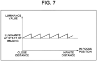
- Fig. 7 is a diagram illustrating luminance variations when the diaphragm is driven under a condition where the luminance value is varied with the change of the in-focus position.
- a system is considered that narrows the aperture of the lens in response to a detection of a specific luminance shift to keep the luminance at a level at the start of imaging as illustrated in Fig. 7 .
- the system illustrated in Fig. 7 that corrects the luminance of the captured images to keep the luminance at a level at the start of imaging causes the image darker, which will color high-luminance portions of the image or prevent the luminance from reaching the saturation point.
- Fig. 8 is a diagram illustrating luminance variation when the diaphragm is driven in the first embodiment.
- designating the magnitude of an exposure level difference when the diaphragm is driven in Fig. 8 makes it possible to perform imaging not to exceed the predetermined exposure as illustrated in Fig. 8 .
- Imaging performed as illustrated in Fig. 8 will enable the luminance to be corrected to be brighter in the image processing in step S407 of Fig. 4 , generating a combined image with a reduced coloring and exposure level difference.
- a second embodiment of the present invention will be described with reference to drawings.
- the exposure determination method in capturing images is changed based on whether to combine the images. The details will be described.
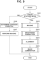
- Fig. 9 is a flowchart illustrating generation of a combined image according to the present embodiment.
- the digital camera 100 supports a plurality of imaging modes, and one of the imaging modes is a focus stacking mode.
- step S901 the control unit 101 determines whether the imaging mode of the digital camera 100 is set to the focus stacking mode. If the imaging mode is the focus stacking mode (YES in step S901), the processing proceeds to step S902, and subsequent processing is the same as the processing described in the first embodiment. If the imaging mode is not the focus stacking mode (NO in step S901), the processing proceeds to step S906.
- step S906 the control unit 101 determines the imaging exposure condition.
- the control unit 101 determines the shutter speed, the F-number, and the ISO sensitivity.
- the user may manually set the exposure condition, or the control unit 101 may automatically set the exposure condition by causing the imaging unit 104 to perform photometry of an object.
- step S907 the imaging unit 104 performs imaging under the exposure condition determined in step S906. In step S907, even if the imaging unit 104 captures a plurality of images, the exposure condition used in capturing of the images and determined in step S906 is maintained.
- images are captured at an exposure darker than a predetermined exposure, and the image processing corrects images to be brighter, which makes it possible to generate a combined image with a reduced coloring and exposure level difference.
- imaging can be performed without changing the exposure.
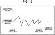
- Fig. 13 is a diagram illustrating variations in luminance due to uneven emission or uneven exposure while a plurality of images is being captured. If the images illustrated in Fig. 13 is combined in some way, uneven brightness appears on a combined image as in the first embodiment. To counteract such uneven brightness, a method of performing imaging with the exposure less than the predetermined value as described in the first embodiment is effective.
- the configuration is not limited to the digital camera.
- a mobile device including an imaging device, or a network camera that can capture images may be used.
- the embodiments of the present invention can be implemented by feeding a program for carrying out one or more of the functions of the above-described embodiments to a system or an apparatus through a network or a storage medium, and by causing one or more processors in a computer of the system or the apparatus to read out and run the program. Further, the embodiments of the present invention can be implemented by a circuit (e.g., ASIC) for carrying out one or more of the functions.
- a circuit e.g., ASIC
- the configurations of the embodiments allow the generation of an excellent combined image with a reduced coloring and brightness level difference.
- Embodiment(s) of the present invention can also be realized by a computer of a system or apparatus that reads out and executes computer executable instructions (e.g., one or more programs) recorded on a storage medium (which may also be referred to more fully as a 'non-transitory computer-readable storage medium') to perform the functions of one or more of the above-described embodiment(s) and/or that includes one or more circuits (e.g., application specific integrated circuit (ASIC)) for performing the functions of one or more of the above-described embodiment(s), and by a method performed by the computer of the system or apparatus by, for example, reading out and executing the computer executable instructions from the storage medium to perform the functions of one or more of the above-described embodiment(s) and/or controlling the one or more circuits to perform the functions of one or more of the above-described embodiment(s).
- computer executable instructions e.g., one or more programs
- a storage medium which may also be referred to more fully as
- the computer may comprise one or more processors (e.g., central processing unit (CPU), micro processing unit (MPU)) and may include a network of separate computers or separate processors to read out and execute the computer executable instructions.
- the computer executable instructions may be provided to the computer, for example, from a network or the storage medium.
- the storage medium may include, for example, one or more of a hard disk, a random-access memory (RAM), a read only memory (ROM), a storage of distributed computing systems, an optical disk (such as a compact disc (CD), digital versatile disc (DVD), or Blu-ray Disc (BD) TM ), a flash memory device, a memory card, and the like.
Landscapes
- Engineering & Computer Science (AREA)
- Multimedia (AREA)
- Signal Processing (AREA)
- Studio Devices (AREA)
- Exposure Control For Cameras (AREA)
- Focusing (AREA)
Applications Claiming Priority (2)
| Application Number | Priority Date | Filing Date | Title |
|---|---|---|---|
| JP2021132311 | 2021-08-16 | ||
| JP2022080615A JP2023026997A (ja) | 2021-08-16 | 2022-05-17 | 撮像装置、撮像方法、プログラムおよび記録媒体 |
Publications (2)
| Publication Number | Publication Date |
|---|---|
| EP4138384A2 true EP4138384A2 (fr) | 2023-02-22 |
| EP4138384A3 EP4138384A3 (fr) | 2023-04-19 |
Family
ID=82846294
Family Applications (1)
| Application Number | Title | Priority Date | Filing Date |
|---|---|---|---|
| EP22185849.1A Pending EP4138384A3 (fr) | 2021-08-16 | 2022-07-19 | Appareil d'imagerie, procédé d'imagerie et support de stockage |
Country Status (3)
| Country | Link |
|---|---|
| US (1) | US11843867B2 (fr) |
| EP (1) | EP4138384A3 (fr) |
| CN (1) | CN115914830A (fr) |
Citations (2)
| Publication number | Priority date | Publication date | Assignee | Title |
|---|---|---|---|---|
| JPH10290389A (ja) | 1997-04-16 | 1998-10-27 | Toyota Motor Corp | マルチフォーカス画像作成方法及び画像作成装置 |
| JP2020107956A (ja) | 2018-12-26 | 2020-07-09 | キヤノン株式会社 | 撮像装置、撮像方法およびプログラム |
Family Cites Families (14)
| Publication number | Priority date | Publication date | Assignee | Title |
|---|---|---|---|---|
| JP3378518B2 (ja) * | 1998-12-03 | 2003-02-17 | 日本電信電話株式会社 | 眼底画像輝度補正方法、その装置及びそのプログラムを記録した記録媒体 |
| JP2004194075A (ja) * | 2002-12-12 | 2004-07-08 | Sony Corp | 撮影システム |
| JP3804617B2 (ja) * | 2003-02-14 | 2006-08-02 | コニカミノルタフォトイメージング株式会社 | 画像処理装置及び方法 |
| JP4524717B2 (ja) * | 2008-06-13 | 2010-08-18 | 富士フイルム株式会社 | 画像処理装置、撮像装置、画像処理方法及びプログラム |
| JP2010271507A (ja) * | 2009-05-21 | 2010-12-02 | Casio Computer Co Ltd | 撮像装置、露出調整方法及びプログラム |
| JP2013153330A (ja) * | 2012-01-25 | 2013-08-08 | Xacti Corp | 電子機器及び撮影制御方法 |
| KR101900097B1 (ko) * | 2012-07-30 | 2018-09-20 | 삼성전자주식회사 | 이미지 캡처 방법 및 이미지 캡처 장치 |
| EP2869023B1 (fr) * | 2013-10-30 | 2018-06-13 | Canon Kabushiki Kaisha | Appareil et procédé de traitement d'images et programme d'ordinateur correspondant |
| US9648249B2 (en) * | 2013-11-20 | 2017-05-09 | Canon Kabushiki Kaisha | Image capturing apparatus, method of controlling the same, and storage medium |
| US10425577B2 (en) * | 2016-08-02 | 2019-09-24 | Panasonic Intellectual Property Management Co., Ltd. | Image processing apparatus and imaging apparatus |
| JP6906947B2 (ja) * | 2016-12-22 | 2021-07-21 | キヤノン株式会社 | 画像処理装置、撮像装置、画像処理方法およびコンピュータのプログラム |
| JP6828069B2 (ja) * | 2019-02-18 | 2021-02-10 | キヤノン株式会社 | 撮像装置、撮像方法およびプログラム |
| JP7422555B2 (ja) * | 2019-04-22 | 2024-01-26 | キヤノン株式会社 | 撮像装置及びその制御方法、プログラム、記憶媒体 |
| JP7409604B2 (ja) * | 2019-12-18 | 2024-01-09 | キヤノン株式会社 | 画像処理装置、撮像装置、画像処理方法、プログラムおよび記録媒体 |
-
2022
- 2022-07-19 EP EP22185849.1A patent/EP4138384A3/fr active Pending
- 2022-07-21 CN CN202210864168.1A patent/CN115914830A/zh active Pending
- 2022-08-03 US US17/817,310 patent/US11843867B2/en active Active
Patent Citations (2)
| Publication number | Priority date | Publication date | Assignee | Title |
|---|---|---|---|---|
| JPH10290389A (ja) | 1997-04-16 | 1998-10-27 | Toyota Motor Corp | マルチフォーカス画像作成方法及び画像作成装置 |
| JP2020107956A (ja) | 2018-12-26 | 2020-07-09 | キヤノン株式会社 | 撮像装置、撮像方法およびプログラム |
Also Published As
| Publication number | Publication date |
|---|---|
| US11843867B2 (en) | 2023-12-12 |
| CN115914830A (zh) | 2023-04-04 |
| US20230048045A1 (en) | 2023-02-16 |
| EP4138384A3 (fr) | 2023-04-19 |
Similar Documents
| Publication | Publication Date | Title |
|---|---|---|
| US10630920B2 (en) | Image processing apparatus | |
| US20130002936A1 (en) | Image pickup apparatus, image processing apparatus, and storage medium storing image processing program | |
| US20110019989A1 (en) | Imaging device and imaging method | |
| JP2009212853A (ja) | ホワイトバランス制御装置およびその制御方法並びに撮像装置 | |
| US10511779B1 (en) | Image capturing apparatus, method of controlling same, and storage medium | |
| EP4002830B1 (fr) | Appareil de capture d'images, procédé de capture d'images et support de stockage | |
| US8570407B2 (en) | Imaging apparatus, image processing program, image processing apparatus, and image processing method | |
| US11375110B2 (en) | Image processing apparatus, image pickup apparatus, image processing method, and non-transitory computer-readable storage medium | |
| US11206350B2 (en) | Image processing apparatus, image pickup apparatus, image processing method, and storage medium | |
| US11044396B2 (en) | Image processing apparatus for calculating a composite ratio of each area based on a contrast value of images, control method of image processing apparatus, and computer-readable storage medium | |
| US12100122B2 (en) | Image processing apparatus for combining a plurality of images, imaging apparatus, imaging method, and recording medium | |
| EP4138384A2 (fr) | Appareil d'imagerie, procédé d'imagerie et support de stockage | |
| US20230066494A1 (en) | Apparatus to perform alignment to images, image processing method to perform alignment to images, and computer readable non-transitory memory to perform alignment to images | |
| US7046289B2 (en) | Automatic focusing device, camera, and automatic focusing method | |
| JP2017182668A (ja) | データ処理装置、撮像装置、及びデータ処理方法 | |
| JP7815301B2 (ja) | 撮像装置及びその制御方法とプログラム | |
| JP2023026997A (ja) | 撮像装置、撮像方法、プログラムおよび記録媒体 | |
| US20240163568A1 (en) | Image capturing apparatus that generates images that can be depth-combined, method of controlling same, and storage medium | |
| JP2010026801A (ja) | 画像処理装置、画像処理プログラム、および画像処理方法 | |
| JP6601062B2 (ja) | 撮像制御装置、撮像制御方法及びプログラム | |
| JP4819737B2 (ja) | 撮像装置及び制御方法 | |
| JP2023026997A5 (fr) | ||
| JP2014139738A (ja) | 画像処理装置、撮像装置及び画像処理方法 |
Legal Events
| Date | Code | Title | Description |
|---|---|---|---|
| PUAI | Public reference made under article 153(3) epc to a published international application that has entered the european phase |
Free format text: ORIGINAL CODE: 0009012 |
|
| STAA | Information on the status of an ep patent application or granted ep patent |
Free format text: STATUS: THE APPLICATION HAS BEEN PUBLISHED |
|
| AK | Designated contracting states |
Kind code of ref document: A2 Designated state(s): AL AT BE BG CH CY CZ DE DK EE ES FI FR GB GR HR HU IE IS IT LI LT LU LV MC MK MT NL NO PL PT RO RS SE SI SK SM TR |
|
| PUAL | Search report despatched |
Free format text: ORIGINAL CODE: 0009013 |
|
| AK | Designated contracting states |
Kind code of ref document: A3 Designated state(s): AL AT BE BG CH CY CZ DE DK EE ES FI FR GB GR HR HU IE IS IT LI LT LU LV MC MK MT NL NO PL PT RO RS SE SI SK SM TR |
|
| STAA | Information on the status of an ep patent application or granted ep patent |
Free format text: STATUS: REQUEST FOR EXAMINATION WAS MADE |
|
| 17P | Request for examination filed |
Effective date: 20231019 |
|
| RBV | Designated contracting states (corrected) |
Designated state(s): AL AT BE BG CH CY CZ DE DK EE ES FI FR GB GR HR HU IE IS IT LI LT LU LV MC MK MT NL NO PL PT RO RS SE SI SK SM TR |
|
| STAA | Information on the status of an ep patent application or granted ep patent |
Free format text: STATUS: EXAMINATION IS IN PROGRESS |
|
| 17Q | First examination report despatched |
Effective date: 20250402 |