EP4138548B1 - Une structure à flottabilité variable pour l'aquaculture - Google Patents
Une structure à flottabilité variable pour l'aquaculture Download PDFInfo
- Publication number
- EP4138548B1 EP4138548B1 EP21721423.8A EP21721423A EP4138548B1 EP 4138548 B1 EP4138548 B1 EP 4138548B1 EP 21721423 A EP21721423 A EP 21721423A EP 4138548 B1 EP4138548 B1 EP 4138548B1
- Authority
- EP
- European Patent Office
- Prior art keywords
- tube
- fluid
- buoyancy
- variable buoyancy
- aquaculture
- Prior art date
- Legal status (The legal status is an assumption and is not a legal conclusion. Google has not performed a legal analysis and makes no representation as to the accuracy of the status listed.)
- Active
Links
Images


Classifications
-
- A—HUMAN NECESSITIES
- A01—AGRICULTURE; FORESTRY; ANIMAL HUSBANDRY; HUNTING; TRAPPING; FISHING
- A01K—ANIMAL HUSBANDRY; AVICULTURE; APICULTURE; PISCICULTURE; FISHING; REARING OR BREEDING ANIMALS, NOT OTHERWISE PROVIDED FOR; NEW BREEDS OF ANIMALS
- A01K61/00—Culture of aquatic animals
- A01K61/60—Floating cultivation devices, e.g. rafts or floating fish-farms
-
- Y—GENERAL TAGGING OF NEW TECHNOLOGICAL DEVELOPMENTS; GENERAL TAGGING OF CROSS-SECTIONAL TECHNOLOGIES SPANNING OVER SEVERAL SECTIONS OF THE IPC; TECHNICAL SUBJECTS COVERED BY FORMER USPC CROSS-REFERENCE ART COLLECTIONS [XRACs] AND DIGESTS
- Y02—TECHNOLOGIES OR APPLICATIONS FOR MITIGATION OR ADAPTATION AGAINST CLIMATE CHANGE
- Y02A—TECHNOLOGIES FOR ADAPTATION TO CLIMATE CHANGE
- Y02A40/00—Adaptation technologies in agriculture, forestry, livestock or agroalimentary production
- Y02A40/80—Adaptation technologies in agriculture, forestry, livestock or agroalimentary production in fisheries management
- Y02A40/81—Aquaculture, e.g. of fish
Definitions
- the present application relates to marine structures, especially for aquaculture operations and in particular sinker tubes, beams or struts for use in aquaculture structures such as cages or pens for housing fish as well as supporting structures for the culture of shellfish, seaweed or any other marine life.
- aquaculture structures such as cages or pens for housing fish as well as supporting structures for the culture of shellfish, seaweed or any other marine life.
- seaweeds any references to fish or shellfish should therefore be interpreted in light of fish or shellfish being an example rather than a limitation of the type of marine life that may be farmed.
- Tensile structures use structural elements that carry only tension and no compression or bending.
- Common tensile structural elements include thin shell membranes and cables.
- Examples of membrane structures include sheets of polymer-based materials (for example rubber, pvc or polyurethane).
- Cables or "tendons" such as ropes, chain, wire cables are 1-dimensional tensile structures that principally resist extension along their axis but resist only limited compression or bending about a transverse axis. Cables, especially ropes based on filament strands can be twisted, knotted, or woven together at regular intervals to form open-meshed nets or fabric sheets.
- Nets are strong membrane structures that can withstand large loads in their plane, while being permeable to fluids and objects smaller than the net's mesh size.
- Fine-meshed fabric sheets can also be coated in rubber or have flexible polymers extruded along their length in order to produce strong, fabric-reinforced membranes that are impermeable to fluids.
- tensile structures are typically very light relative to the volumes they can enclose and the loads they can resist under certain conditions, while they can also be collapsed, folded or rolled for transport and storage. They are also resilient to dynamic environmental loads as they are typically flexible and can be configured to shed excess loads through dynamic flexibility. For these reasons, tensile structures are particularly popular for temporary structures subject to dynamic environmental loads. Examples of uses would include tents and for building structures at remote locations where the logistics for delivery of heavy building materials is costly (for example rope bridges in mountainous locations). As such, they are also very well adapted to marine applications for mooring systems and also of particular interest in fisheries where they can be used for trawl nets that can be winched and stowed onto net drums.
- tensile structures A limitation of tensile structures is that they obtain their strength and structural form by being pre-tensioned and cannot form stable structures alone.
- Rigid plastic pipe structures are commonly employed as floating collars or sinker rings for aquaculture pens or cages. As these are not tensile structures, they are not generally collapsible/inflatable and once they are configured for use, they remain in this configuration throughout their operating lifetime. Alternatives include steel collar structures, though plastic retains a certain degree of structural flexibility that reduces loads under dynamic environmental conditions, in particular wave loads.
- Sinker rings are essentially a means of increasing resistance to loading on the nets that form the aquaculture pens and cages. Sinker rings are required to provide negatively buoyant tensioning forces that pull the nets downwards from the floating collar or floating ring which generally rests on the surface of the sea, thus giving the pen or cage a more defined volumetric structure in the water.
- the concept of sinker rings has evolved from attaching individual weights to a submerged collar, as it has been discovered that the structure of a ring provides the necessary weight to maintain the pen in the desired configuration and also resists bending moments impacted by the subsea environment more efficiently than individual weights. As the prior art sinker rings are large in size and difficult to manoeuvre into position, lifting machinery is often needed to install and handle sinker rings.
- Nets also need to be periodically replaced whilst keeping the stock within the containment area contained, which results in further handling issues with the prior art sinker rings.
- Some operators revert to individual weights due to handling difficulties of sinker rings. Frequently, divers are required to inspect or to aid net replacement operations where there is not a way to raise weights to the surface easily.
- the tension is provided by anchors at each end of the headrope which are in turn connected to the headrope by mooring lines. Where suspended biomass growth is significant, the required pre-tension can become significant.
- mussel longlines are currently suspended from headropes that are up to 200m long and anchor blocks of up to 4 tonnes in weight are required to keep such headropes in tension.
- the mooring lines at either end of a headline are also typically short relative to the water depth.
- the "scope" of an anchor line is the ratio of the line length to the water depth and this ratio typically does not exceed 3 for mussel lines.
- Light ropes are typically used rather than chain and because of the pre-tension from the longline, the mooring line is taught, such that the anchor is typically loaded with a vertical component, limiting anchor choice to types that can resist such loads (e.g. gravity anchor, screw-in anchor, suction anchor).
- US 1 336 356 A discloses a fish trap comprising a variable buoyancy beam of the related art.
- the first fluid has a density less dense than the density of the water in which the beam is to be positioned.
- the first fluid stores energy when it is compressed and has a low specific gravity and the second fluid is incompressible with a higher specific gravity so that the stored energy of the compressed first fluid can be used to expel the second incompressible fluid from the tube without the need for another source of energy.
- the first fluid is air and the second fluid is water, it will be appreciated that the air may be compressed air.
- the negatively buoyant constituent may be positioned to be in intimate contact with a wall of the tube.
- the negatively buoyant constituent comprises a high-density ballasting material, for example a metal.
- the high density ballasting material may be integrated into the wall of the tube.
- the metal extends across the wall from an interior of the tube to an exterior of the tube.
- the metal is attached to, and extends about, the exterior of the tube.
- variable buoyancy beams may be connected at their ends to form a truss structure.
- the tube wall (16) is suitably formed by an impermeable membrane.
- the impermeable membrane may be selected such that it only resists substantial loads that put the membrane in positive tensile stress along its plane.
- suitable membranes are sheets of polymer-based materials (for example rubber, PVC or polyurethane) that may also be used as a matrix material for reinforcing fibres such as nylon, polyester, aramid or steel fibres. Textiles like canvas, GORE-TEX TM could also be utilised to form a suitable membrane material. Fine-meshed fabric sheets can also be coated in rubber or have flexible polymers extruded along their length in order to produce strong, fabric-reinforced membranes that are impermeable to fluids.
- the length of the beam (100) will depend on the desired application, being at least 5 times its cross-sectional diameter. In many applications, the length of the beam will be at least 10 times its cross-sectional diameter.
- typical head rope (306) lengths can be 200 m or more in prior art and where a head beam (302) might be applied as depicted in Figure 16a the cross-sectional diameter will be in a range of 100 mm to 400 mm. If formed from a single head beam, the length of such a head beam (302) would be of the order of 1000 times its diameter, though practical solutions may be formed by connecting a number of head beam (302) elements to make up the required structure.
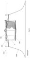
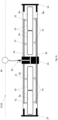
- Figure 6a shows a beam (100) configured to be a generally straight beam (100) with sealed end fittings (24) that facilitate connections to moorings, aquaculture structures or other beam elements.
- End connections can be incorporated into the end fitting (24).
- the end connections may include a flanged joint to facilitate bolt fasteners or the inclusion of pad-eyes to receive conventional attachments such as shackles or other cable termination options.
- the end fitting will provide a grooved or barbed outer cylindrical surface of a diameter similar to the inner diameter of the wall (16) of the tube (2), commonly referred to as a "hose tail", in the art. With such an approach the tube (2) fits tightly over the "hose tail” forming a sealed interface between the tube (2) and the end fitting (24).
- the end fitting can also comprise adjustable clamps in order to apply pressure to the outside of the wall (16) of the tube to increase the contact force at the sealed interface, commonly being threaded "hose clips" in the art or segmented clamps with threaded screw features to apply a distributed contact load at the interface.
- the sealed end fittings (24) can also be configured to optionally provide termination points for an encapsulating net structure (20), such that the net structure is pre-tensioned to a desirable degree upon inflation of the tube (2).
- the end fittings (24) can also be configured to provide threaded cable tensioners to adjust the level of pre-tension in individual cable elements (22) of the encapsulating net structure (20), similar to a "turnbuckle” or “bottle screw", which would be familiar to those skilled in the art.
- Figure 7 shows a beam (100) configured to be a generally straight beam (100) where the membrane wall (16) is extended to form a generally continuous hemispherical or torispherical shell to seal the ends of the tube (2).
- an encapsulating net structure (20) is shown to extend around the ends of the tube such that it can be longitudinally pre-tensioned by the pressurised tube (2) and can also be used to facilitate end-to-end connections of multiple beams using state of the art cable connectors.
- Cable elements (22) can be pre-tensioned by including features known in the art such as "turnbuckles” or webbing tensioners with ratchets and clamps which would be familiar to those skilled in the art.
- variable buoyancy beam (100) can be configured to connect to one another in order to create a variable buoyancy truss structure (404) as shown in Figure 9 .
- a truss may have application for marine structures generally and not necessarily restricted to aquatic structures.
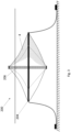
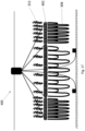
- FIG. 11 shows a centrally supported toroidal beam structure (402), formed from 6 straight variable buoyancy beams (100) that are also supported by spoke elements (tendons, struts or beams) that connect the toroidal structure to a supporting hub structure.
- spoke elements tendons, struts or beams
- Separate beams (100) may be advantageous should manufacturing constraints limit the length of the individual beams (100).
- Separate but connected beams (100) with independently controlled buoyancy may allow control of the buoyancy distribution and floating attitude of the overall structure. This may be advantageous for operational reasons.
- Separate beams (100) advantageously also provide additional redundancy functions as the failure of one beam element does not necessarily result in the failure of the entire structure (200, 202, 204, 206, 300, 302, 400, 402, 404).
- Two or more beams, each floating with a waterplane-area may be braced side by side in order to provide hydrostatic roll stability and potentially to support an access deck walkway structure or any other structure that requires such stability, for example for a float ring (202). Otherwise any floating or submerged beams may be braced side by side to provide desirable bending or buoyancy properties in aggregate.
- Two or more fluids (8a, 8b) are used to pressurise the tube (2).
- the two or more fluids (8a, 8b) must be of different densities and the ratio of those fluids (8a, 8b) in the tube (2) must be controllable.
- At least one of those fluids (8a, 8b) must have a density equal to or lower than that of the ambient water in which the variable buoyancy beam (100) will be submerged.
- the first fluid (8a) is compressible and the second fluid (8b) is incompressible.
- the fluids (8a, 8b) are separated from each other using at least one internal bladder (10). The use of internal bladders (10) ensures that fluids can be controlled separately and remain un-mixed for ballast control.
- the bladders are formed by a membrane of suitably low flexural rigidity and such that the pressure differential between the first fluid and the second fluid is small.
- Internal bladders (10) or other cell membranes may be advantageously used to control the movement of the varying density fluids (8a, 8b) within the tube (2) so that general internal ballast distribution is maintained.
- the internal bladders (10) can be secured within a positional envelope within the tube (2) using ropes or other means to improve ballast stability under dynamic loading.
- the bladder (10) is formed by a suitably flexible impermeable membrane that may either fully enclose a volume of the first fluid or fully enclose a volume of the second fluid or alternatively may be attached to the wall (16) of the tube (2) in such a way as to separate volumes of the two fluids (8a, 8b) enclosed by the tube wall (16) and the bladder (10) membrane.
- the bladder (10) is configured such that the ratio of the volume of the first fluid (8a) to the second fluid (8b) within the tube (2) may be varied.
- the membrane material of the bladder (10) is flexible, such that the stresses induced in the bladder (10) wall are small over the required range of volume changes and such that the difference in pressures on either side of the bladder (10) wall at a given location over the required range of volumetric variation do not exceed 2 bar, preferably not exceeding 0.5 bar.
- the membrane material of the bladder is preferably of a flexural rigidity not exceeding 1 Nm for tubes of 500 mm diameter or smaller, where the flexural rigidity is affected by the membrane thickness and materials properties, notably the Young's modulus and Poisson's ratio.
- the bladder (10) membrane will have sufficient surface area to take up the required volume change or optionally be of a suitably low in-plane stiffness to stretch to the required volumes, while inducing only a limited pressure differential between the first fluid (8a) and the second fluid (8b).
- Suitable bladder membrane materials include but are not limited to natural or synthetic rubber sheeting such as Butyl, latex or silicone rubber, PVC, Polyurethene or Polyethelene sheet materials and rubber-coated fabric membranes using polyester, nylon or aramid fibres or other impermeable fabric materials such as those under the brand names of Dacron or Gore-Tex.
- the wall thickness of the bladder membrane will not exceed 2% of the beam diameter (in a range of up to 1 mm for 50 mm diameter beams and up to 30 mm for 1.5 m diameter beams, for example).
- the at least one bladder (10) may comprise a plurality of internal bladders distributed at a variety of locations within the tube. Where there is a plurality of bladders, the bladders may be discretely formed, or they may be co-formed together. Optionally, such plurality of internal bladders being formed by a flexible closed cell foam structure.
- a fluid may be a liquid or gas.
- suitable fluids are air and saltwater. It will be understood however that the other fluids can be used to effect a variation in the pressure of the tube (2) and a change of buoyancy of the overall beam within the present context.
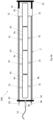
- a variable buoyancy beam is provided with a plurality of internal bladders (10).
- the individual internal bladders (10) are inflated from a single common inflation manifold (33) with check valves (31) at the inlet to each bladder (10).
- air is a low-density compressible fluid
- water is a substantially incompressible fluid of a density equal or similar to the ambient fluid in which the beam (100) is immersed.
- air is the first fluid (8a) and seawater is the second fluid (8b)
- the buoyancy of the beam (100) can be reduced by adding water to the interior of the tube (2) in a manner such that the fixed mass of air (8a) is compressed to a reduced volume with a correspondingly reduced buoyancy.
- this can be used advantageously to simultaneously increase beam stiffness and to reduce the freeboard of the beam in order to attenuate wave-induced response of the structure, such as a mussel longline (300).
- the beam (100) also includes a negatively buoyant constituent (6)
- water can be added to reduce the volume of air to the point at which no longer provides sufficient buoyancy to keep the beam (100) afloat.
- a negatively buoyant constituent (6) By continuing to add water to a beam (100) with a negatively buoyant constituent (6) the volume of air can be reduced to the point at which it is strongly negatively buoyant.
- a negatively buoyant beam (100) can be deployed advantageously to aquaculture structures that may require a negatively buoyant pre-tensioning force, such as for a sinker ring (204) as depicted in Figure 22 and Figure 23 .
- the fixed mass of air (8a) may be pressurised to approximately 10 bar thus resulting in a substantial reduction of volume of the fixed mass of air (8a).
- the increased pressure in the tube (2) also affects the desired stiffness and buckling strength of the beam (100) in its reduced buoyancy, pressurised condition.
- valves (30,35) can be opened such that the energy stored in compressed air (8a) pressure pushes water (8b) out of the interior of the tube (2) and such that the buoyancy is increased in a controlled way as the air (8a) expands to displace the emitted water (8b). It will be appreciated that such an operation will also need to consider the effects of ambient pressure at the installed depth. Tube inflation pressures up to the order of 10 bar over the ambient are anticipated, which may be at depths in the range of 5m to 50m (0.5 to 5 bar ambient pressures).
- the normal usage of a sinker ring (504) to maintain downward pressure on the netting of the aquaculture pen structure is provided by the one or more variable buoyancy beams (100) while the normal usage of a floater ring (502) to maintain positive buoyancy and overall heave stability of the aquaculture pen structure is also provided by the one or more variable buoyancy beams (100) in accordance with the present teaching.
- the sinker ring (204) may comprise a variable buoyancy beam (100) that includes also a negatively buoyant constituent (6) differs from conventional sinker rings (504) in that it is configured to adopt either a positive buoyancy mode (to float to the surface to aid operations) or a negative buoyancy mode (to act as a net tensioning feature). It is possible to switch between positive buoyancy or negative buoyancy once or multiple times with relative ease as required.
- the high-density ballast material (14) is not placed in the water in isolation, but is part of the one or more variable buoyancy beams (100) forming the sinker ring (204) - the negative buoyancy of the high-density ballast material (14) works against the positive buoyancy of at least one of the fluids (8a, 8b) in the tube (2).
- the gradual reduction of buoyancy due to the variation of the ratio of fluids (8a, 8b) will result in the effect of the high-density ballast material (14) becoming increasingly dominant until a threshold is reach wherein the sinker ring (204) is neutrally buoyant.
- the high-density ballast material (14) can be installed inside the enclosed volume of the tube (2) or integrated with the collapsible membrane wall (16) of the tube (2), potentially as a reinforcing structural material, or it can be suspended outside but integral to the tube (2), potentially forming a part of the encapsulating net structure (20)
- the vertical spar (206) comprising one or more variable buoyancy beams (100) differs from a conventional vertical spar structures used to support aquaculture nets in that the one or more variable buoyancy beams (100) can be inflated in order to apply tension to the net (4) and also collapsed and folded to support operations by selectively adding or removing either the first fluid (8a) or second fluid (8b) from the hollow tube (2) such that the pre-tension in the membrane wall (16) is selectively varied to provide the desired mechanical properties of the variable buoyancy beam (100).
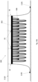
- the floats (304) may be replaced by a variable buoyancy beam (100) of the type described generally herein arranged in a vertical orientation. In this vertical orientation, the beam may be attached at one end to the head rope (306).
- Such beams (100) advantageously being configured to have a variable buoyancy that can passively compensate for the growth of biomass on drop ropes (308) and optionally being configured to be flexible in bending in order to attenuate wave loads being transmitted to the head rope (306) by the beam (100).
- FIG 16a illustrates a general layout of a mussel culture system (300) in accordance with the present teaching.
- the mussel culture system (300) comprises a head beam (302) formed by one or more variable buoyancy beams (100), which comprise a hollow tube (2) formed with a membrane wall (16), configured to retain at least a first fluid (8a) and second fluid (8b).
- the membrane wall is impermeable.
- the membrane wall (16) is suitably selected so that when fluid is removed from the beam (100), the beam (100) may collapse upon itself.
- the beam is preferably foldable when collapsed.
- the one or more variable buoyancy beams (100) of the centrally-supported polygonal ring (402) are encapsulated in a rope net (20) and optionally includes a negatively buoyant constituent (6).
- the one or more beams (100) have a variable buoyancy and, by changing the buoyancy of the one or more beams (100), it is possible to control the freeboard or residual buoyancy of the centrally-supported polygonal ring (402) as well as compensate for any changes in the gravity loads applied to the ring (402) by any attached mussel culture drop ropes (308) or attached seaweed biomass (312).
- centrally-supported polygonal ring (402) which can be stabilised about a hub structure by the elastic properties of the centrally supported polygonal toroid (402) such that its level of submergence can be configured or varied depending on the buoyancy of the of the one or more variable buoyancy beams (100), including through the application of a pressure-activated or float-activated valve (35) as described above to release water when submergence exceeds a threshold in response to biomass weight increases.
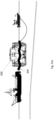
- Figure 18a shows a mussel and seaweed culture system (300) based on a centrally supported polygonal ring (402) attached to a floating hub structure, whereby the ring (402) is de-ballasted to the surface for operational purposes such as inspection, harvest or maintenance.
- Figure 18b shows a mussel and seaweed culture system (300) based on a centrally supported polygonal ring (402) attached to a floating hub structure such that the ring (402) is collapsed and in a buoyant condition as part of installation and/or demobilisation operations.
- the sinker ring (204) differs from conventional sinker rings (504) in that it is configured to adopt either a positive buoyancy mode (to float to the surface to aid operations) or a negative buoyancy mode (to act as a net tensioning feature). It is possible to switch between positive buoyancy or negative buoyancy once or multiple times with relative ease.
- the internal volume of the tube (2) is preferably filled with a first fluid (8a) and a second fluid (8b) of different densities.
- the buoyancy in any one instance is related to the extent by which the tube (2) is filled with at least a first fluid (8a) or a second fluid (8b) or a combination of both fluids.
- the internal volume of the tube (2) can be operatively pressurised and depressurised through controlled movement of at least one of the first fluid (8a) or the second fluid (8b) between the exterior and the interior of the tube (2).
- the ratio of the first fluid (8a) to the second fluid (8b) is carefully controlled.
- a bladder is employed to separate the two fluids.
- the tube (2) may be filled completely with either the first fluid (8a) or the second fluid (8b) or a combination thereof.
- a fluid may be a liquid or gas. Examples of suitable fluids are air and saltwater. It will be understood that other fluids can also be used to affect a variation in the pressure of the tube (2) and a change of buoyancy of the overall sinker tube.
- a pump will be provided in fluid communication with one or more points around the tube (2) to deliver seawater at elevated pressures and/or to extract seawater from the internal volume of the tube to reduce the pressure on the tube.
- a shut-off valve and/or check valve can be included for each connection.
- the beam (tube) may be (2) at least partially collapsible.
- a collapsible tube (2) is advantageous as it means that the whole sinker ring is partially collapsible and can be more easily stored and moved on site or within harbours.
- the tube (2) of the collapsible sinker ring (204) may be inflated (or filled by any other means) to pressurise the collapsible sinker ring (204) such that it forms a substantially rigid support member.
- the tube wall may be a rubber coated fabric or other membrane material such as for example PVC plastic sheeting or impermeable textiles (canvas, gortex etc). Such a construction means that the tube wall does not provide a large resistance to bending when the tube is unpressurised.
- air is a low-density compressible fluid
- sea water is a substantially incompressible fluid of a density equal to the ambient fluid in which the sinker ring (204) is immersed. Since air is the first fluid (8a) and seawater is the second fluid (8b), where the mass of air within the tube (2) is fixed, the buoyancy of the sinker ring (204) can be made negative by adding seawater to the interior of the tube (2) in a manner such that the fixed mass of air (8a) is compressed to a volume with a corresponding density which no longer provides sufficient buoyancy to keep the sinker ring (204) afloat.
- the negative buoyancy of the high-density ballast material (14) works against the positive buoyancy of at least one of the fluids (8a, 8b) in the tube (2).
- the gradual removal of at the fluids (8a, 8b) which provides positive buoyancy will result in the effect of the high-density ballast material (14) becoming increasingly dominant until a threshold is reach wherein the sinker ring (204) is neutrally buoyant. Further removal of the fluid (8a, 8b) which is provides positive buoyancy beyond this point will cause the sinker ring (204) to become increasingly negatively buoyant.
- FIG 6a illustrates an elevation and cross-sectional views of an exemplary variable buoyancy beam (100) according to one aspect of this application.
- the variable buoyancy beam comprises a hollow tube (2) formed with an impermeable wall (16), optionally being a foldable and collapsible membrane wall.
- the variable buoyancy beam is configured to retain air as a first fluid (8a) in a single internal bladder (10) and seawater as a second fluid (8b) wherein the air is compressible and has a density less dense than the density of the seawater in which the beam (100) is to operate.
- the variable buoyancy beam in Figure 6a is suitably sealed with flanged end fittings (24).
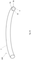
- Figure 10a illustrates a perspective view of the variable buoyancy beam (100) where the beam is curved into a ring.
- the beam constitutes a negatively buoyant constituent (6) in the form of continuously distributed high-density ballasting materials (14), examples of this type of continuously distributed high-density ballasting materials include dense elongate members as per Figure 14a or steel ropes as per Figure 14b such that it forms a sinker ring (204);
- Figure 10b illustrates a perspective view of a sinker ring (204) showing an alternative negatively buoyant constituent (6) in the form of intermittently spaced high-density ballasting materials (14) in a rigid tube of variable buoyancy;
- Figure 11 illustrates a perspective view of a centrally-supported polygonal toroid (402) formed from a plurality, in the example shown six, variable buoyancy beams (100) of the type illustrated in Figure 7 .
- Radial tendons connect the toroidal polygon to a central hub structure, the tendons comprising rope, chain, wire or elastomeric tendon materials.
- Figure 14a illustrates an alternative ballasting option for a variable buoyancy beam (100).
- the tube (2) itself is manufactured from high density ballast material (14) or wires or strands of high-density ballast material (14) could be embedded in the tube (2).
- the flexibility of wire strands and wire rope options for high density ballast material (14) ensures that the collapsibility of the variable buoyancy beam (100) is not hindered by the additional material.
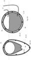
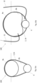
- Figure 15c illustrates a cross section of the variable buoyancy beam (100) in a rigid and neutrally buoyant configuration when the tube (2) is filled with a minority volume of a low-density fluid (8a) at high pressure and a majority volume of high-density fluid (8b) at high pressure.
- Figure 15d illustrates a cross section of the variable buoyance beam (100) in a rigid and negatively buoyant configuration when the tube (2) is filled with a further minority of low-density fluid (8a) at high pressure and a further majority of high-density fluid (8b) at high pressure.
- Figure 15e illustrates a cross section of the variable buoyance beam (100) in a rigid and negatively buoyant configuration when the tube (2) is filled with an almost full majority of high density fluid (8b) at high pressure and almost negligible minority of low density fluid at high pressure (8a).
- Figure 16b illustrates a submerged layout of a shellfish, suitably mussel, culture system (300) with a head beam (302) in a fully submerged position, formed by one or more variable buoyancy beams (100), similar to that illustrated in Figure 6c .
- the beam (100) has a variable buoyancy and, by changing the buoyancy of the beam (100), it is possible to control the buoyancy of the head beam (302) as well as compensate for any changes in the gravity loads applied to the beam (302) by the attached mussel culture drop ropes (308).
- variable buoyancy may, as explained above, be controlled passively by float-actuated valves (35), which are configured to release the seawater (8b) from the connected beam (100), when the submergence exceeds a threshold set by the attached float (36).
- variable buoyancy beam (100) of the head beam (302) is encapsulated in a rope net (20), such that the net provides attachment points for the dropper ropes (308).
- FIG 17 illustrates a general layout of a shellfish, suitably mussels, and seaweed culture system (300) in a normal operating position.
- the mussel culture system (300) comprises a centrally-supported polygonal ring (402) similar to that illustrated in Figure 11 , attached to a floating hub structure.
- the centrally-supported polygonal ring is formed by one or more variable buoyancy beams (100), onto which shellfish drop ropes (308) and seaweed biomass (312) are attached.
- Figure 18a shows the mussel and seaweed culture system (300) illustrated in Figure 17 , wherein the ring (402) is de-ballasted to the surface for operational purposes such as to facilitate inspection, harvest or maintenance.
- Figure 18b shows the mussel and seaweed culture system (300) illustrated in Figure 17 . wherein the ring (402) is in a collapsed, buoyant condition to facilitate installation and/or demobilisation operations.
- FIGS 19 , 20 , 21 and 22 illustrate a typical deployment sequence for a collapsible sinker ring (204) comprising one or more variable buoyancy beams (100) as will now be explained.
- the sinker ring (204) comprising one or more variable buoyancy beams (100) are provided in a collapsed buoyant state and the negative buoyancy constituent (6) is already incorporated into the collapsible tube (2).
- a fluid has been added to the interior of the collapsible tube (2) such that the tube (2) has become partially rigid.
- the fluid which has been added is of a density relative to seawater and of a quantity such that is does not blance the negative buoyancy of the negative buoyancy constituent (6), thus the sinker ring (204) has also become negatively buoyant.
- the one or more variable buoyancy tubes (100) comprising the sinker ring (204) have been filled with at least one fluid such that the sinker ring (204) is now in its fully inflated rigid condition.
- the sinker ring (204) is negatively buoyant, however it has not yet reached its optimum level of negative buoyancy wherein the sinker ring (204) is tensioning the nets (4) which are attached to both the floating collar (502) and the sinker ring (204).
- the fluid ratio has been further adjusted such that the combination of fluid within the tube (2) and the negative buoyancy constituent (6) are providing a level of negative buoyancy to the one or more variable buoyancy beams (100) which is sufficient to sink the sinker ring (204) into the water wherein the sinker ring (204) is held in place at a depth from the surface of the water which is defined by the structure of the net (4) of the aquaculture pen (200), or more particularly the length of net (4) available (or other structural features which are attached to the floating collar (502)) to span between the floating collar (502) and the sinker ring (204).
- Figure 23a illustrates an exemplary first step in another exemplary deployment sequence wherein a sinker ring (204) comprises a centrally-supported polygonal toroid (402), formed from one or more variable buoyancy beams (100) and a negative buoyancy constituent (6) and is attached to a floating hub structure to form a net pen system (200) for the culture of fish.
- Figure 23a shows an initially buoyant and collapsed configuration within the aquaculture net pen (200). Such a configuration can be usefully adopted during a transit of the net pen (200) to its installation location. On arrival at its installation location, the pen may then be deployed.
- Figure 23b illustrates an exemplary second step in the deployment sequence wherein the aquaculture pen structure (200) is first connected to an offshore mooring (1100).
- Figure 23c shows how, having been tethered to the offshore mooring, the pen may be coupled at multiple points to the seabed (1105).
- the submerged sinker ring can be stabilised about the hub structure by the elastic properties of the centrally supported polygonal toroid (402), as described in WO2020212613-A1 , such that its level of submergence can be configured or varied depending on the buoyancy of the one or more variable buoyancy beams (100), and Figure 23f illustrates a final point in the deployment sequence wherein the one or more variable buoyancy beams (100) are de-ballasted to a point wherein the sinker ring is located at a lower region of the aquaculture net pen (200) and thus applies negative buoyancy tensioning forces to the aquaculture net pen (200).
Landscapes
- Life Sciences & Earth Sciences (AREA)
- Environmental Sciences (AREA)
- Marine Sciences & Fisheries (AREA)
- Zoology (AREA)
- Animal Husbandry (AREA)
- Biodiversity & Conservation Biology (AREA)
- Farming Of Fish And Shellfish (AREA)
Claims (14)
- Une poutre à flottabilité variable (100), convenant pour être utilisée en aquaculture, la poutre (100) comprenant :un tube (2) allongé creux comprenant une paroi externe (16), le tube étant configuré pour retenir un premier fluide compressible (8a) d'une première densité et un deuxième fluide incompressible (8b) d'une deuxième densité ;au moins une poche interne (10) formée d'une membrane imperméable souple, fournie au sein du tube (2) allongé creux pour séparer le premier fluide (8a) du deuxième fluide (8b) où il est possible de faire varier de façon opérationnelle la flottabilité de la poutre (100) par variation sélective d'un rapport du premier fluide (8a) au deuxième fluide (8b) au sein du tube (2), caractérisée en ce que la paroi externe (16) du tube (2) allongé creux est imperméable.
- Une poutre à flottabilité variable (100) selon la revendication 1, encapsulée en outre dans une structure formant filet de renforcement (20), comprenant un réseau d'un ou de plusieurs éléments formant câbles (22) et les éléments formant câbles (22) étant sélectionnés parmi un ou plusieurs éléments parmi de la corde, des chaînes, du fil, des courroies de maillage, et du tissu maillé, où de façon appropriée la structure formant filet de renforcement (20) fournit des points d'attache à la poutre pour suspendre des structures d'aquaculture (4, 306, 308, 312) dans un environnement aquatique, la charge de points d'attache étant répartie sur le tube (2) par la structure formant filet de renforcement (20).
- Une poutre à flottabilité variable (100) selon n'importe quelle revendication précédente, dans laquelle l'au moins une poche comprend une pluralité de poches internes (10) réparties au niveau d'emplacements le long du tube (2), dans laquelle les poches de la pluralité de poches sont assujetties longitudinalement au sein du tube (2) afin de maintenir leur position longitudinale générale au sein du tube pour une stabilité globale de ballast.
- La poutre à flottabilité variable (100) selon n'importe laquelle des revendications 1 à 3 dans laquelle le premier fluide (8a) est contenu au sein d'une structure en mousse à alvéoles fermées (26) dans le tube (2), la structure en mousse à alvéoles fermées étant souple.
- Une poutre à flottabilité variable (100) selon la revendication 2, où la paroi de tube (16) est formée à partir d'une membrane souple, le tube (2) ayant un état plié et un état déployé, de telle sorte que lors de l'utilisation il est possible de faire varier de façon opérationnelle une résistance de la poutre (100) par l'introduction d'au moins un fluide parmi le premier fluide (8a) ou le deuxième fluide (8b) afin de fournir une pré-contrainte dans la paroi en membrane (16) en forçant le tube vers l'état déployé de sorte que le tube (2) résiste à un gauchissement ou un flambage dus à des charges externes appliquées sur la poutre à flottabilité variable (100), où de façon appropriée le filet d'encapsulation (20) et ses éléments formant câbles (22) sont pré-tendus par des forces de contact appliquées par la paroi en membrane (16) du tube (2) dans son état déployé et où des éléments formant câbles (22) avec une composante longitudinale le long de l'axe de la poutre (100) sont pré-tendus de sorte que la poutre à flottabilité variable (100) agit pour résister à un gauchissement ou un flambage dus à l'application de charges externes.
- La poutre à flottabilité variable (100) selon n'importe quelle revendication précédente, un composant de flottaison négative (6) s'étendant autour ou au sein du tube, la flottabilité de la poutre à flottabilité variable (100) étant une combinaison de la flottabilité du tube (2) et du composant de flottaison négative (6).
- La poutre à flottabilité variable (100) selon n'importe quelle revendication précédente, la poutre à flottabilité variable (100) comprenant une vanne (30, 31, 35), la vanne étant configurée pour commander l'accès et la sortie d'au moins un fluide parmi un premier fluide (8a) ou un deuxième fluide (8b) entre l'intérieur du tube (2) et l'extérieur du tube (2), la vanne (35) étant de façon appropriée configurée pour s'ouvrir à une profondeur de submersion seuil et permettre à n'importe quel fluide parmi le premier fluide (8a) ou le deuxième fluide (8b) de s'écouler entre l'intérieur du tube (2) et l'extérieur du tube (2) afin d'influer sur un changement de flottabilité de compensation souhaité, la vanne étant facultativement actionnée de façon passive par des changements de pression ambiante ou par des charges appliquées à partir d'un flotteur attaché (36).
- La poutre à flottabilité variable (100) de la revendication 3, dans laquelle les poches de la pluralité de poches internes (10) sont raccordées chacune par l'intermédiaire de vannes (30) à au moins un collecteur commun (33, 34).
- La poutre à flottabilité variable (100) selon la revendication 7, comprenant en outre une pompe, la pompe étant configurée pour déplacer au moins un fluide parmi un premier fluide (8a) ou un deuxième fluide (8b) entre l'intérieur du tube (2) et l'extérieur du tube (2) par l'intermédiaire des vannes (30, 31, 35).
- La poutre à flottabilité variable (100) de n'importe lesquelles des revendications 8 à 9, comprenant en outre au moins un ombilical (12) qui est configuré pour raccorder la vanne (30, 31, 35) à une source du premier fluide (8a) ou du deuxième fluide (8b).
- La poutre à flottabilité variable (100) selon n'importe quelle revendication précédente, la poutre à flottabilité variable (100) consistant en une ou plusieurs poutres (100), les une ou plusieurs poutres (100) étant :a) configurées pour former une structure toroïdale, telle qu'un anneau incurvé (202, 204) ou un tore polygonal (402),b) configurées pour former un tore polygonal à support central (402), où les une ou plusieurs poutres (100) sont raccordées à une structure à moyeu avec des poutres en rayons, des entretoises ou des câbles, qui sont facultativement des tendons élastiques de stabilisation, ouc) étant raccordées au niveau de leurs extrémités afin de former une structure en treillis (404).
- La poutre à flottabilité variable (100) selon la revendication 6, où le composant de flottaison négative (6) est en contact étroit avec une paroi (16) du tube (2), le composant de flottaison négative comprenant un matériau de ballast à densité élevée (14), le matériau de ballast à densité élevée (14) comprenant de façon appropriée un métal.
- La poutre à flottabilité variable (100) de la revendication 1 ou de la revendication 2, où la poche interne est définie par une membrane s'étendant dans un plan s'étendant longitudinalement le long du tube, les côtés de la membrane étant définis par les points d'origine et de terminaison d'un arc d'une paroi interne du tube de telle sorte que la membrane divise effectivement le tube en une première région pour le premier fluide (8a) et une deuxième région pour le deuxième fluide (8b).
- Un système d'aquaculture (200) comprenant une poutre à flottabilité variable selon n'importe quelle revendication précédente, où :a) le système d'aquaculture est un système de filet d'aquaculture comprenant au moins un filet couplé à la poutre à flottabilité variable (100),b) le système d'aquaculture est un système de culture de mollusques et crustacés (300) comprenant au moins un substrat pour la culture de mollusques et crustacés couplé à la poutre à flottabilité variable, ouc) le système d'aquaculture est un système de culture d'algues marines ou d'algues (300) comprenant au moins un substrat pour la culture d'algues marines ou d'algues couplé à la poutre à flottabilité variable (100).
Applications Claiming Priority (3)
| Application Number | Priority Date | Filing Date | Title |
|---|---|---|---|
| GB2005731.1A GB2594263A (en) | 2020-04-20 | 2020-04-20 | A variable buoyancy sinker ring |
| GBGB2015781.4A GB202015781D0 (en) | 2020-10-05 | 2020-10-05 | A variable buoyancy structure for aquaculture |
| PCT/EP2021/060279 WO2021214087A1 (fr) | 2020-04-20 | 2021-04-20 | Structure à flottabilité variable pour aquaculture |
Publications (3)
| Publication Number | Publication Date |
|---|---|
| EP4138548A1 EP4138548A1 (fr) | 2023-03-01 |
| EP4138548B1 true EP4138548B1 (fr) | 2024-07-10 |
| EP4138548C0 EP4138548C0 (fr) | 2024-07-10 |
Family
ID=75674785
Family Applications (1)
| Application Number | Title | Priority Date | Filing Date |
|---|---|---|---|
| EP21721423.8A Active EP4138548B1 (fr) | 2020-04-20 | 2021-04-20 | Une structure à flottabilité variable pour l'aquaculture |
Country Status (3)
| Country | Link |
|---|---|
| EP (1) | EP4138548B1 (fr) |
| AU (1) | AU2021259227B2 (fr) |
| WO (1) | WO2021214087A1 (fr) |
Cited By (1)
| Publication number | Priority date | Publication date | Assignee | Title |
|---|---|---|---|---|
| WO2026037847A1 (fr) * | 2024-08-13 | 2026-02-19 | Impact9 Energy & Marine Limited | Régulateur de flottabilité activé par les vagues |
Families Citing this family (2)
| Publication number | Priority date | Publication date | Assignee | Title |
|---|---|---|---|---|
| CN114303992B (zh) * | 2021-11-15 | 2023-04-07 | 苑丽娜 | 一种兽医手术用无菌型动物头套 |
| CN114698606B (zh) * | 2022-04-18 | 2023-02-03 | 中国水产科学研究院东海水产研究所 | 便于调节深度的南极磷虾拖网桁杆装置 |
Citations (14)
| Publication number | Priority date | Publication date | Assignee | Title |
|---|---|---|---|---|
| US1336356A (en) | 1918-02-08 | 1920-04-06 | Eugene M Johnson | Fish-trap |
| US4244323A (en) | 1978-05-11 | 1981-01-13 | Bridgestone Tire Company Limited | Apparatus for floating and sinking fish breeding netted tanks |
| US5299530A (en) | 1992-07-17 | 1994-04-05 | Occidental Research Corporation | Submergible fish cage |
| US5655938A (en) | 1994-04-11 | 1997-08-12 | Huguenin; John E. | Variable buoyancy ballast and flotation unit for submerged objects or structures |
| WO1999034668A1 (fr) | 1998-01-08 | 1999-07-15 | Helgeland Plast A.S | Parc piscicole submersible |
| WO2009094196A2 (fr) | 2008-01-23 | 2009-07-30 | Stuart Bussell | Système submersible de culture d'algues aquatiques |
| US7984685B1 (en) | 2009-05-21 | 2011-07-26 | The United States Of America As Represented By The Secretary Of The Navy | Neutrally buoyant submerged system using greater density ballast fluid |
| US8136470B1 (en) | 2010-06-03 | 2012-03-20 | The United States Of America As Represented By The Secretary Of The Navy | System and method for modifying the net buoyancy of underwater objects |
| JP2014113141A (ja) | 2012-11-14 | 2014-06-26 | Mesco Inc | 浮沈式生け簀 |
| KR20150120845A (ko) | 2014-04-18 | 2015-10-28 | 정은진 | 부력조절형 부이 |
| US9395461B2 (en) | 2009-12-22 | 2016-07-19 | Pgs Geophysical As | Depth steerable seismic source array |
| US10051844B2 (en) | 2014-04-01 | 2018-08-21 | Carter Newell | Modular submersible aquaculture raft |
| WO2020212613A1 (fr) | 2019-04-18 | 2020-10-22 | Impact9 Energy And Marine Ltd. | Système d'enclos submersible |
| US10945417B2 (en) | 2018-07-24 | 2021-03-16 | Running Tide Technologies, Inc. | Systems and methods for the cultivation of aquatic animals |
-
2021
- 2021-04-20 EP EP21721423.8A patent/EP4138548B1/fr active Active
- 2021-04-20 AU AU2021259227A patent/AU2021259227B2/en active Active
- 2021-04-20 WO PCT/EP2021/060279 patent/WO2021214087A1/fr not_active Ceased
Patent Citations (14)
| Publication number | Priority date | Publication date | Assignee | Title |
|---|---|---|---|---|
| US1336356A (en) | 1918-02-08 | 1920-04-06 | Eugene M Johnson | Fish-trap |
| US4244323A (en) | 1978-05-11 | 1981-01-13 | Bridgestone Tire Company Limited | Apparatus for floating and sinking fish breeding netted tanks |
| US5299530A (en) | 1992-07-17 | 1994-04-05 | Occidental Research Corporation | Submergible fish cage |
| US5655938A (en) | 1994-04-11 | 1997-08-12 | Huguenin; John E. | Variable buoyancy ballast and flotation unit for submerged objects or structures |
| WO1999034668A1 (fr) | 1998-01-08 | 1999-07-15 | Helgeland Plast A.S | Parc piscicole submersible |
| WO2009094196A2 (fr) | 2008-01-23 | 2009-07-30 | Stuart Bussell | Système submersible de culture d'algues aquatiques |
| US7984685B1 (en) | 2009-05-21 | 2011-07-26 | The United States Of America As Represented By The Secretary Of The Navy | Neutrally buoyant submerged system using greater density ballast fluid |
| US9395461B2 (en) | 2009-12-22 | 2016-07-19 | Pgs Geophysical As | Depth steerable seismic source array |
| US8136470B1 (en) | 2010-06-03 | 2012-03-20 | The United States Of America As Represented By The Secretary Of The Navy | System and method for modifying the net buoyancy of underwater objects |
| JP2014113141A (ja) | 2012-11-14 | 2014-06-26 | Mesco Inc | 浮沈式生け簀 |
| US10051844B2 (en) | 2014-04-01 | 2018-08-21 | Carter Newell | Modular submersible aquaculture raft |
| KR20150120845A (ko) | 2014-04-18 | 2015-10-28 | 정은진 | 부력조절형 부이 |
| US10945417B2 (en) | 2018-07-24 | 2021-03-16 | Running Tide Technologies, Inc. | Systems and methods for the cultivation of aquatic animals |
| WO2020212613A1 (fr) | 2019-04-18 | 2020-10-22 | Impact9 Energy And Marine Ltd. | Système d'enclos submersible |
Cited By (1)
| Publication number | Priority date | Publication date | Assignee | Title |
|---|---|---|---|---|
| WO2026037847A1 (fr) * | 2024-08-13 | 2026-02-19 | Impact9 Energy & Marine Limited | Régulateur de flottabilité activé par les vagues |
Also Published As
| Publication number | Publication date |
|---|---|
| WO2021214087A1 (fr) | 2021-10-28 |
| CA3180730A1 (fr) | 2021-10-28 |
| AU2021259227A1 (en) | 2023-01-05 |
| AU2021259227B2 (en) | 2025-04-24 |
| EP4138548A1 (fr) | 2023-03-01 |
| EP4138548C0 (fr) | 2024-07-10 |
Similar Documents
| Publication | Publication Date | Title |
|---|---|---|
| EP4138548B1 (fr) | Une structure à flottabilité variable pour l'aquaculture | |
| JP6923547B2 (ja) | 半潜水型養殖システム | |
| US5251571A (en) | Submersible cage system for culturing aquatic animals | |
| US8869746B2 (en) | Mooring structure with habitat features for marine animals | |
| CN107926802B (zh) | 一种沉浮式深海气囊养殖网箱 | |
| JP7201269B2 (ja) | 魚養殖用システムおよび方法 | |
| KR101845500B1 (ko) | 잠수형 가두리장치 | |
| JP2022542995A (ja) | 外洋水産養殖用魚囲い | |
| CN115281133A (zh) | 一种深海升降式养殖网箱 | |
| US6467993B1 (en) | Fish attractive device | |
| NO349679B1 (en) | Fish farming system and method of operation thereof | |
| US20050235921A1 (en) | Self-deployable open ocean aquaculture cages and underwater structures | |
| NO344390B1 (en) | Fish farming structure | |
| WO1992003921A1 (fr) | Systeme de cage submersible pour l'elevage d'animaux aquatiques | |
| CA3180730C (fr) | Structure a flottabilite variable pour aquaculture | |
| EP1528855A1 (fr) | Enclos pour poissons | |
| KR101707936B1 (ko) | 무게 분산형 암해가 장착된 안강망 어구 | |
| WO2014072788A1 (fr) | Système et procédé de pisciculture | |
| NO20171477A1 (en) | Installation for cultivating marine biomass | |
| CN213756268U (zh) | 一种沉浮式深海养殖网箱 | |
| GB2594263A (en) | A variable buoyancy sinker ring | |
| GB2643408A (en) | A wave-activated buoyancy regulator | |
| GB2594095A (en) | Wave energy device | |
| CN208001877U (zh) | 一种沉浮式深海气囊养殖网箱 | |
| WO2007131600A1 (fr) | Enclos d'aquaculture avec moyens de raccordement à absorption d'énergie |
Legal Events
| Date | Code | Title | Description |
|---|---|---|---|
| STAA | Information on the status of an ep patent application or granted ep patent |
Free format text: STATUS: UNKNOWN |
|
| STAA | Information on the status of an ep patent application or granted ep patent |
Free format text: STATUS: THE INTERNATIONAL PUBLICATION HAS BEEN MADE |
|
| PUAI | Public reference made under article 153(3) epc to a published international application that has entered the european phase |
Free format text: ORIGINAL CODE: 0009012 |
|
| STAA | Information on the status of an ep patent application or granted ep patent |
Free format text: STATUS: REQUEST FOR EXAMINATION WAS MADE |
|
| 17P | Request for examination filed |
Effective date: 20221117 |
|
| AK | Designated contracting states |
Kind code of ref document: A1 Designated state(s): AL AT BE BG CH CY CZ DE DK EE ES FI FR GB GR HR HU IE IS IT LI LT LU LV MC MK MT NL NO PL PT RO RS SE SI SK SM TR |
|
| DAV | Request for validation of the european patent (deleted) | ||
| DAX | Request for extension of the european patent (deleted) | ||
| GRAP | Despatch of communication of intention to grant a patent |
Free format text: ORIGINAL CODE: EPIDOSNIGR1 |
|
| STAA | Information on the status of an ep patent application or granted ep patent |
Free format text: STATUS: GRANT OF PATENT IS INTENDED |
|
| INTG | Intention to grant announced |
Effective date: 20230915 |
|
| GRAJ | Information related to disapproval of communication of intention to grant by the applicant or resumption of examination proceedings by the epo deleted |
Free format text: ORIGINAL CODE: EPIDOSDIGR1 |
|
| STAA | Information on the status of an ep patent application or granted ep patent |
Free format text: STATUS: REQUEST FOR EXAMINATION WAS MADE |
|
| GRAJ | Information related to disapproval of communication of intention to grant by the applicant or resumption of examination proceedings by the epo deleted |
Free format text: ORIGINAL CODE: EPIDOSDIGR1 |
|
| STAA | Information on the status of an ep patent application or granted ep patent |
Free format text: STATUS: GRANT OF PATENT IS INTENDED |
|
| GRAP | Despatch of communication of intention to grant a patent |
Free format text: ORIGINAL CODE: EPIDOSNIGR1 |
|
| INTC | Intention to grant announced (deleted) | ||
| INTG | Intention to grant announced |
Effective date: 20240208 |
|
| RIN1 | Information on inventor provided before grant (corrected) |
Inventor name: FITZGERALD, JOHN |
|
| GRAS | Grant fee paid |
Free format text: ORIGINAL CODE: EPIDOSNIGR3 |
|
| GRAA | (expected) grant |
Free format text: ORIGINAL CODE: 0009210 |
|
| STAA | Information on the status of an ep patent application or granted ep patent |
Free format text: STATUS: THE PATENT HAS BEEN GRANTED |
|
| AK | Designated contracting states |
Kind code of ref document: B1 Designated state(s): AL AT BE BG CH CY CZ DE DK EE ES FI FR GB GR HR HU IE IS IT LI LT LU LV MC MK MT NL NO PL PT RO RS SE SI SK SM TR |
|
| REG | Reference to a national code |
Ref country code: CH Ref legal event code: EP |
|
| REG | Reference to a national code |
Ref country code: DE Ref legal event code: R096 Ref document number: 602021015483 Country of ref document: DE |
|
| U01 | Request for unitary effect filed |
Effective date: 20240730 |
|
| U07 | Unitary effect registered |
Designated state(s): AT BE BG DE DK EE FI FR IT LT LU LV MT NL PT SE SI Effective date: 20240814 |
|
| PG25 | Lapsed in a contracting state [announced via postgrant information from national office to epo] |
Ref country code: GR Free format text: LAPSE BECAUSE OF FAILURE TO SUBMIT A TRANSLATION OF THE DESCRIPTION OR TO PAY THE FEE WITHIN THE PRESCRIBED TIME-LIMIT Effective date: 20241011 Ref country code: PL Free format text: LAPSE BECAUSE OF FAILURE TO SUBMIT A TRANSLATION OF THE DESCRIPTION OR TO PAY THE FEE WITHIN THE PRESCRIBED TIME-LIMIT Effective date: 20240710 |
|
| PG25 | Lapsed in a contracting state [announced via postgrant information from national office to epo] |
Ref country code: HR Free format text: LAPSE BECAUSE OF FAILURE TO SUBMIT A TRANSLATION OF THE DESCRIPTION OR TO PAY THE FEE WITHIN THE PRESCRIBED TIME-LIMIT Effective date: 20240710 |
|
| PG25 | Lapsed in a contracting state [announced via postgrant information from national office to epo] |
Ref country code: ES Free format text: LAPSE BECAUSE OF FAILURE TO SUBMIT A TRANSLATION OF THE DESCRIPTION OR TO PAY THE FEE WITHIN THE PRESCRIBED TIME-LIMIT Effective date: 20240710 Ref country code: RS Free format text: LAPSE BECAUSE OF FAILURE TO SUBMIT A TRANSLATION OF THE DESCRIPTION OR TO PAY THE FEE WITHIN THE PRESCRIBED TIME-LIMIT Effective date: 20241010 |
|
| PG25 | Lapsed in a contracting state [announced via postgrant information from national office to epo] |
Ref country code: RS Free format text: LAPSE BECAUSE OF FAILURE TO SUBMIT A TRANSLATION OF THE DESCRIPTION OR TO PAY THE FEE WITHIN THE PRESCRIBED TIME-LIMIT Effective date: 20241010 Ref country code: PL Free format text: LAPSE BECAUSE OF FAILURE TO SUBMIT A TRANSLATION OF THE DESCRIPTION OR TO PAY THE FEE WITHIN THE PRESCRIBED TIME-LIMIT Effective date: 20240710 Ref country code: HR Free format text: LAPSE BECAUSE OF FAILURE TO SUBMIT A TRANSLATION OF THE DESCRIPTION OR TO PAY THE FEE WITHIN THE PRESCRIBED TIME-LIMIT Effective date: 20240710 Ref country code: GR Free format text: LAPSE BECAUSE OF FAILURE TO SUBMIT A TRANSLATION OF THE DESCRIPTION OR TO PAY THE FEE WITHIN THE PRESCRIBED TIME-LIMIT Effective date: 20241011 Ref country code: ES Free format text: LAPSE BECAUSE OF FAILURE TO SUBMIT A TRANSLATION OF THE DESCRIPTION OR TO PAY THE FEE WITHIN THE PRESCRIBED TIME-LIMIT Effective date: 20240710 |
|
| PGFP | Annual fee paid to national office [announced via postgrant information from national office to epo] |
Ref country code: IS Payment date: 20250219 Year of fee payment: 5 |
|
| PLBI | Opposition filed |
Free format text: ORIGINAL CODE: 0009260 |
|
| PG25 | Lapsed in a contracting state [announced via postgrant information from national office to epo] |
Ref country code: SM Free format text: LAPSE BECAUSE OF FAILURE TO SUBMIT A TRANSLATION OF THE DESCRIPTION OR TO PAY THE FEE WITHIN THE PRESCRIBED TIME-LIMIT Effective date: 20240710 |
|
| PGFP | Annual fee paid to national office [announced via postgrant information from national office to epo] |
Ref country code: NO Payment date: 20250219 Year of fee payment: 5 |
|
| PLAX | Notice of opposition and request to file observation + time limit sent |
Free format text: ORIGINAL CODE: EPIDOSNOBS2 |
|
| PG25 | Lapsed in a contracting state [announced via postgrant information from national office to epo] |
Ref country code: CZ Free format text: LAPSE BECAUSE OF FAILURE TO SUBMIT A TRANSLATION OF THE DESCRIPTION OR TO PAY THE FEE WITHIN THE PRESCRIBED TIME-LIMIT Effective date: 20240710 |
|
| PG25 | Lapsed in a contracting state [announced via postgrant information from national office to epo] |
Ref country code: SK Free format text: LAPSE BECAUSE OF FAILURE TO SUBMIT A TRANSLATION OF THE DESCRIPTION OR TO PAY THE FEE WITHIN THE PRESCRIBED TIME-LIMIT Effective date: 20240710 |
|
| 26 | Opposition filed |
Opponent name: MARBOT EHF. Effective date: 20250409 |
|
| U20 | Renewal fee for the european patent with unitary effect paid |
Year of fee payment: 5 Effective date: 20250411 |
|
| PGFP | Annual fee paid to national office [announced via postgrant information from national office to epo] |
Ref country code: GB Payment date: 20250411 Year of fee payment: 5 |
|
| PGFP | Annual fee paid to national office [announced via postgrant information from national office to epo] |
Ref country code: IE Payment date: 20250402 Year of fee payment: 5 |
|
| PLBB | Reply of patent proprietor to notice(s) of opposition received |
Free format text: ORIGINAL CODE: EPIDOSNOBS3 |
|
| REG | Reference to a national code |
Ref country code: CH Ref legal event code: H13 Free format text: ST27 STATUS EVENT CODE: U-0-0-H10-H13 (AS PROVIDED BY THE NATIONAL OFFICE) Effective date: 20251125 |
|
| PG25 | Lapsed in a contracting state [announced via postgrant information from national office to epo] |
Ref country code: MC Free format text: LAPSE BECAUSE OF FAILURE TO SUBMIT A TRANSLATION OF THE DESCRIPTION OR TO PAY THE FEE WITHIN THE PRESCRIBED TIME-LIMIT Effective date: 20240710 |
|
| PG25 | Lapsed in a contracting state [announced via postgrant information from national office to epo] |
Ref country code: CH Free format text: LAPSE BECAUSE OF NON-PAYMENT OF DUE FEES Effective date: 20250430 |
|
| PG25 | Lapsed in a contracting state [announced via postgrant information from national office to epo] |
Ref country code: RO Free format text: LAPSE BECAUSE OF FAILURE TO SUBMIT A TRANSLATION OF THE DESCRIPTION OR TO PAY THE FEE WITHIN THE PRESCRIBED TIME-LIMIT Effective date: 20240710 |