EP4138622B1 - Distributeur à transfert mécanique et procédé - Google Patents
Distributeur à transfert mécanique et procédé Download PDFInfo
- Publication number
- EP4138622B1 EP4138622B1 EP20931719.7A EP20931719A EP4138622B1 EP 4138622 B1 EP4138622 B1 EP 4138622B1 EP 20931719 A EP20931719 A EP 20931719A EP 4138622 B1 EP4138622 B1 EP 4138622B1
- Authority
- EP
- European Patent Office
- Prior art keywords
- roll
- transfer
- dispenser
- dispensing position
- disk
- Prior art date
- Legal status (The legal status is an assumption and is not a legal conclusion. Google has not performed a legal analysis and makes no representation as to the accuracy of the status listed.)
- Active
Links
Images


Classifications
-
- A—HUMAN NECESSITIES
- A47—FURNITURE; DOMESTIC ARTICLES OR APPLIANCES; COFFEE MILLS; SPICE MILLS; SUCTION CLEANERS IN GENERAL
- A47K—SANITARY EQUIPMENT; ACCESSORIES THEREFOR, e.g. TOILET ACCESSORIES
- A47K10/00—Body-drying implements; Toilet paper; Holders therefor
- A47K10/24—Towel dispensers; Toilet paper dispensers
- A47K10/32—Dispensers for paper towels or toilet paper
- A47K10/34—Dispensers for paper towels or toilet paper dispensing from a web, e.g. with mechanical dispensing means
- A47K10/36—Dispensers for paper towels or toilet paper dispensing from a web, e.g. with mechanical dispensing means with mechanical dispensing, roll switching or cutting devices
-
- A—HUMAN NECESSITIES
- A47—FURNITURE; DOMESTIC ARTICLES OR APPLIANCES; COFFEE MILLS; SPICE MILLS; SUCTION CLEANERS IN GENERAL
- A47K—SANITARY EQUIPMENT; ACCESSORIES THEREFOR, e.g. TOILET ACCESSORIES
- A47K10/00—Body-drying implements; Toilet paper; Holders therefor
- A47K10/24—Towel dispensers; Toilet paper dispensers
- A47K10/32—Dispensers for paper towels or toilet paper
- A47K2010/3233—Details of the housing, e.g. hinges, connection to the wall
-
- A—HUMAN NECESSITIES
- A47—FURNITURE; DOMESTIC ARTICLES OR APPLIANCES; COFFEE MILLS; SPICE MILLS; SUCTION CLEANERS IN GENERAL
- A47K—SANITARY EQUIPMENT; ACCESSORIES THEREFOR, e.g. TOILET ACCESSORIES
- A47K10/00—Body-drying implements; Toilet paper; Holders therefor
- A47K10/24—Towel dispensers; Toilet paper dispensers
- A47K10/32—Dispensers for paper towels or toilet paper
- A47K2010/324—Jumbo rolls
-
- A—HUMAN NECESSITIES
- A47—FURNITURE; DOMESTIC ARTICLES OR APPLIANCES; COFFEE MILLS; SPICE MILLS; SUCTION CLEANERS IN GENERAL
- A47K—SANITARY EQUIPMENT; ACCESSORIES THEREFOR, e.g. TOILET ACCESSORIES
- A47K10/00—Body-drying implements; Toilet paper; Holders therefor
- A47K10/24—Towel dispensers; Toilet paper dispensers
- A47K10/32—Dispensers for paper towels or toilet paper
- A47K2010/3246—Locking mechanisms for the housing
-
- A—HUMAN NECESSITIES
- A47—FURNITURE; DOMESTIC ARTICLES OR APPLIANCES; COFFEE MILLS; SPICE MILLS; SUCTION CLEANERS IN GENERAL
- A47K—SANITARY EQUIPMENT; ACCESSORIES THEREFOR, e.g. TOILET ACCESSORIES
- A47K10/00—Body-drying implements; Toilet paper; Holders therefor
- A47K10/24—Towel dispensers; Toilet paper dispensers
- A47K10/32—Dispensers for paper towels or toilet paper
- A47K2010/3253—Dispensers for paper towels or toilet paper with one or more reserve rolls
-
- A—HUMAN NECESSITIES
- A47—FURNITURE; DOMESTIC ARTICLES OR APPLIANCES; COFFEE MILLS; SPICE MILLS; SUCTION CLEANERS IN GENERAL
- A47K—SANITARY EQUIPMENT; ACCESSORIES THEREFOR, e.g. TOILET ACCESSORIES
- A47K10/00—Body-drying implements; Toilet paper; Holders therefor
- A47K10/24—Towel dispensers; Toilet paper dispensers
- A47K10/32—Dispensers for paper towels or toilet paper
- A47K10/34—Dispensers for paper towels or toilet paper dispensing from a web, e.g. with mechanical dispensing means
- A47K10/36—Dispensers for paper towels or toilet paper dispensing from a web, e.g. with mechanical dispensing means with mechanical dispensing, roll switching or cutting devices
- A47K2010/3681—Dispensers for paper towels or toilet paper dispensing from a web, e.g. with mechanical dispensing means with mechanical dispensing, roll switching or cutting devices characterised by the way a new paper roll is loaded in the dispenser
-
- A—HUMAN NECESSITIES
- A47—FURNITURE; DOMESTIC ARTICLES OR APPLIANCES; COFFEE MILLS; SPICE MILLS; SUCTION CLEANERS IN GENERAL
- A47K—SANITARY EQUIPMENT; ACCESSORIES THEREFOR, e.g. TOILET ACCESSORIES
- A47K10/00—Body-drying implements; Toilet paper; Holders therefor
- A47K10/24—Towel dispensers; Toilet paper dispensers
- A47K10/32—Dispensers for paper towels or toilet paper
- A47K10/34—Dispensers for paper towels or toilet paper dispensing from a web, e.g. with mechanical dispensing means
- A47K10/38—Dispensers for paper towels or toilet paper dispensing from a web, e.g. with mechanical dispensing means the web being rolled-up
- A47K2010/3863—Dispensers for paper towels or toilet paper dispensing from a web, e.g. with mechanical dispensing means the web being rolled-up with roll rotation braking devices
Definitions
- Toilet tissue dispensers which dispense rolls of toilet tissue.
- many toilet dispensers are suitable for dispensing oversized or jumbo rolls of materials.
- Such jumbo rolls typically have a diameter between about 20 to 30 centimeters.
- Dispensers for oversized or jumbo rolls of toilet tissue are commonly provided in commercial establishments in order to minimize the frequency of roll replacement. Although the replacement interval is extended, the disposition and replacement of the partially spent roll, i.e. the stub roll, remains a problem.
- the present disclosure is directed to a dispenser that can facilitate easier removal of stub rolls and installment of new rolls of material.
- the dispenser includes a housing having a rear housing and an openable cover that defines a housing interior.
- the housing interior is configured to receive a roll of material having a diameter.
- the roll of material may include an oversized or jumbo roll of material.
- the rear housing includes a backplate to be mounted to a mounting surface, such as the stall wall of a commercial restroom.
- the housing interior is configured to receive and hold a roll of material in a first dispensing position and a second dispensing position.
- the dispenser further includes a roll transfer apparatus. Upon the diameter of roll of material reaching a transfer diameter size, the roll transfer apparatus facilitates movement of the roll of material from the first dispensing position to the second dispensing position.
- a roll transfer apparatus including a transfer arm configured to hold the roll of material in a first dispensing position.
- the transfer arm includes a first end having a transfer arm roller configured to engage the roll of material and a second end engaged with a transfer disk.
- the transfer apparatus also includes a transfer latch having a first end configured to engage the transfer disk. When the diameter of the roll of material reaches a certain transfer diameter size, the second end of the transfer arm engages the first end of the transfer latch in such a manner that causes the transfer latch to disengage from the transfer disk to facilitate movement of the roll of material from the first dispensing position to the second dispensing position.
- the transfer disk includes a notch configured to securely engage the transfer latch when the jumbo roll is in the first dispensing position.
- the transfer disk also includes a spring engagement mechanism configured to be secured to an extension spring located on a recessed portion of the backside of the rear housing.
- the transfer disk also includes a transfer disk protrusion that is configured to engage a transfer disc control slot that is located in the backplate of the rear housing.
- the extension spring rotates the transfer disk to an extent permitted by the transfer disc control slot, which forces the transfer arm roller against the roll of material, thus, facilitating movement of the roll of material from the first dispensing position to the second dispensing position.
- the transfer disk and transfer latch can be securely attached to the first side of the backplate that generally forms and faces the housing interior.
- the dispenser includes one or more rollers and a ramp configured to facilitate moving the roll of material from the first position to the second position.
- the ramp may have an opening to allow for dispensing of the material from the jumbo roll.
- the ramp generally includes a first end located in closer proximity to the roll of material in the first dispensing position and a second end located closer in proximity to the roll of material in the second dispensing position. The first end of the ramp is elevated in comparison to the second end of the ramp to allow for gravitational forces to further facilitate movement of the roll of material from the first dispensing position to the second dispensing position.
- the roll of material can be supported by a stub roll support base and an upper stub roll support member when the roll of material is in the second dispensing position.
- the housing of the dispenser can also include an access opening configured to permit a user to access a sheet of material from the roll of material.
- the access opening may define a perimeter having one or more tear members situated along at least a portion of the perimeter.
- the tear members can facilitate tearing of the material from the jumbo roll, such that it can then be utilized by the end user.
- the roll of material can include a jumbo roll of toilet tissue.
- the dispenser includes a locking mechanism for locking the openable cover to the rear housing.
- the openable cover can be attached to the rear housing via a hinge.
- the present disclosure is generally directed to a dispenser for a dispenser for a roll of material. More particularly, the present dispenser is directed to a dispenser that includes a roll transfer apparatus for moving a roll of material from a first dispensing position to a second dispensing position. Moving the roll of material from the first dispensing position to the second dispensing position allows for restroom personnel to more easily install or replace jumbo rolls of material in the dispenser. When the roll of material is located in the second dispensing position, the first dispensing position is available for accepting a new roll of material. Accordingly, when the restroom personnel opens the cover of the dispenser, they can easily insert a new roll of material in the first dispensing position without having to first remove the partially used roll, also referred to as a stub roll.
- the washroom personnel must set the new roll of material down on a surface in the restroom. This is undesirable because it can introduce contaminants to the new roll of material.
- the disclosed dispenser eliminates the need to sit the new roll of material down while removing the stub roll from the dispenser.
- the dispenser disclosed herein allows for easier replacement of the partially used roll, which can save time for restroom personnel. In commercial restrooms having multiple jumbo roll dispensers, the time to service and replace partially used rolls can be greatly reduced allowing the restroom personnel to more efficiently service the commercial restroom.
- the disclosed dispenser includes a first dispensing position and a second dispensing position, that can assist with eliminating waste in the form of unused product, such as toilet paper, that may be on the partially used roll.
- a first dispensing position and a second dispensing position that can assist with eliminating waste in the form of unused product, such as toilet paper, that may be on the partially used roll.
- many known jumbo roll dispensers only have one dispensing position for the roll of material. Accordingly, when using known dispensers, the washroom personnel must remove the partially used roll in order to refurnish the dispenser with a new roll of material. Material remaining unused on the stub roll generates product waste and economic loss. In certain situations where the partially used roll still contains a decent amount of material, the restroom personnel must decide whether to replace the partially used roll or not.
- the roll may become fully depleted before the restroom personnel can make it back to replace the partially used roll with a new roll. Having fully depleted rolls is undesirable as there is no product available to the user.
- the present dispenser eliminates this problem. For instance, the product transfer apparatus automatically transfers the partially used roll to a second dispensing position once the roll reaches a certain diameter. Product is still able to be dispensed from the second position and the restroom personnel is free to provide a new roll of material in the first dispensing position. Accordingly, material can be fully removed from the partially used roll in the second dispensing position and then product can be accessed from the roll in the first dispensing position.
- the dispenser includes a rear housing and an openable cover defining a housing interior.
- the housing interior is configured to receive a roll of material having a diameter.
- the rear housing includes a backplate that is configured to be mounted to a mounting surface.
- the housing interior is configured to receive and hold a roll of material in a first dispensing position and a second dispensing position.
- the dispenser also includes a roll transfer apparatus.
- the roll transfer apparatus is located in the interior housing. Upon the diameter of the roll of material reaching a transfer diameter size, the roll transfer apparatus facilitates movement of the roll of material from the first dispensing position to the second dispensing position.
- the roll transfer apparatus includes a transfer arm configured to hold the jumbo roll in a first dispensing position.
- the transfer arm includes a first end having a transfer arm roller configured to engage the roll of material and a second end engaged with a transfer disk.
- the roll transfer apparatus also includes a transfer latch having a first end including a hook configured to engage the transfer disk. Upon the roll of material reaching the transfer diameter size, the second end of the transfer arm engages the transfer latch such that the hook disengages from the transfer disk to facilitate movement of the roll of material from the first dispensing position to the second dispensing position.
- the dispenser 10 includes a rear housing 12 including a backplate 18.
- the dispenser 10 also includes an openable cover 14, the openable cover 14 encloses at least a portion of said backplate 18 to form a housing having a housing interior 16 so as to retain at least one roll of a roll of material 20.
- the dispenser 10 can be mounted to a mounting surface such as the wall of a restroom or the stall of a restroom.
- the dispenser 10 can be mounted to the mounting surface via any suitable mechanism.
- the dispenser 10 can include a rear housing 12 and an openable cover 14 that can have any desired overall shape.
- the dispenser 10 can include a two-part configuration.
- the dispenser 10 can include a rear housing 12 and an openable cover 14.
- the openable cover 14 can be pivotally mounted to the rear housing 12 using any suitable means.
- hinges can be used to connect the openable cover 14 to the rear housing 12.
- the openable cover 14 can be completely separable from the rear housing 12.
- the openable cover 14 generally defines the front face 15 and at least a portion of the sidewalls 19 of the dispenser 10, while the rear housing 12 defines the back of the dispenser 10.
- the sidewalls 19 may be defined entirely by the openable cover 14.
- the rear housing 12 can also define at least a portion of the sidewalls 19 of the dispenser 10.
- the side walls may be entirely defined by the rear housing 12.
- the sidewalls 19 may be entirely defined by the openable cover 14.
- the openable cover 14 may have sidewalls that cooperate with the sidewalls of the rear housing 12. The openable cover 14 may be in a closed or open position. The openable cover 14 may form at least a portion of the top wall 13 of the dispenser 10. As shown in Fig. 2 , the openable cover 14 is in a closed position, thus covering the interior of the dispenser 10.
- the rear housing 12 and openable cover 14 can define housing interior 16 for housing the operational components of the dispenser 10, as well as rolls of sheet material to be dispensed, including a roll of material 20.
- the rear housing 12 can also form at least a portion of the bottom 21 or bottom surface of the dispenser 10.
- the openable cover 14 defines at least a portion of the housing interior 16.
- the openable cover 14 can include a locking mechanism configured to lock the openable cover 14 to the rear housing 12 such that product contained within the dispenser cannot be accessed without engaging the locking mechanism.
- the locking mechanism can be a lock configured to open with a key.
- the contents of the housing interior 16 cannot be accessed without having the key.
- Certain restroom personnel that service the restroom may have the key for accessing the dispenser 10.
- the dispenser 10 also includes a roll transfer apparatus 40 that is located generally in the housing interior 16.
- the roll transfer apparatus 40 can include a transfer arm 50, a transfer disk 60, and a transfer latch 70. Elements of the roll transfer apparatus 40 can be affixed to a first side 130 of the backplate 18 in any suitable manner. Exploded view of the transfer arm 50, transfer disk 60, and transfer latch 70 are shown in Figs. 3-5 .
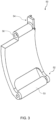
- the transfer arm 50 can include a first end 52 and a second end 54.
- the transfer arm 50 includes a transfer arm roller 53 generally located along the first end 52 of the transfer arm 50.
- the transfer arm roller 53 is configured such that it engages at least a portion of the surface of the roll of material 20 when the roll of material 20 is in a first dispensing position 22 in the dispenser 10.
- the transfer arm 50 also includes a second end 54 configured to securely engage with the transfer disk 60.
- the transfer arm 50 can be securely attached to the transfer disk via any suitable mechanism.
- the transfer arm 50 also includes a transfer arm pivot 56 and a transfer arm torsion spring 57 generally located about the second end 54 of the transfer arm 50.
- the transfer arm pivot 56 and transfer arm torsion spring 57 allow for movement of the transfer arm 50 about the transfer arm pivot 56 as the diameter of the roll of material 20 changes.
- the transfer arm torsion spring 57 holds the transfer arm roller 53 against the roll of material 20.
- the transfer arm roller 53 As the product is dispensed, the transfer arm roller 53 is held in engagement with the roll of material 20 via the transfer arm torsion spring 57. In addition to tracking with the roll of material 20, the transfer arm roller 53 applies light pressure to the roll of material 20 as the material is dispensed, which helps to reduce overpsin of the product during roll dispensing.
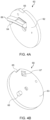
- the transfer disk 60 includes a first side 62 and a second side 63.
- the first side 62 generally faces the housing interior 16 and the second side 63 of the transfer disk 60 generally faces the backplate 18 of the rear housing 12.
- the first side 62 of the transfer disk 60 includes a transfer arm engagement member 66 having a jumbo roll engagement surface 64 thereon.
- the transfer arm engagement member 66 is configured to engage and secure at least a portion of the transfer arm 50 to the transfer disk 60.
- the transfer arm 50 may be secured to the transfer arm engagement member 66 via any suitable mechanism.
- the jumbo roll engagement surface 64 is also configured to engage at least a portion of the roll of material 20 when the roll of material 20 is in a first dispensing position 22.
- the transfer disk 60 also includes a notch 65.
- the notch 65 is configured to engage the transfer latch 70. In some embodiments, the notch 65 engages the transfer latch 70 when the roll of material 20 is in the first dispensing position 22.
- the second side 63 of the transfer disk 60 includes a spring engagement mechanism 67 and a transfer disk protrusion 68.
- the spring engagement mechanism 67 is configured to engage an extension spring 82 located about the second side 131 of the backplate.
- the transfer disk protrusion 68 is configured to engage with a transfer disk control slot 84 also located on the backplate 18 of the rear housing 12.
- the transfer latch 70 includes a first end 72 and a second end 73.
- the first end 72 of the transfer latch 70 is configured to engage the transfer disk 60.
- the first end 72 includes a transfer disk engagement mechanism configured to releasably attach the first end 72 of the transfer latch 70 to the transfer disk 60.
- Any suitable transfer disk engagement mechanism can be utilized.
- the first end 72 of the transfer latch 70 can include a hook 74.
- the hook 74 is configured such that it engages the notch 65 of the transfer disk 60 when the roll of material 20 is in the first dispensing position 22.
- the transfer disk engagement mechanism can include a flange or protrusion configured to engage the notch 65 of the transfer disk 60.
- the transfer disk engagement mechanism can include a groove configured to engage a surface or flange located on the transfer disk 60.
- the transfer disk engagement mechanism can include any releasable fastening mechanism such as members, protrusions, flanges, etc. configured to engage and releasably secure the transfer latch 70 to the transfer disk 60.
- the transfer latch 70 also includes a transfer latch pivot 75 and a transfer latch torsion spring 76 generally located about the second end 73 of the transfer latch 70.
- the transfer latch pivot 75 and transfer latch torsion spring 76 allow for movement of the transfer latch 70 about the pivot 75 as the diameter of the roll of material 20 changes.
- the transfer latch 70 is held in engagement with the transfer disk 60 via the transfer disk notch 65 via the transfer latch torsion spring 76.
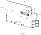
- the rear housing 18 has a second side 131, which corresponds to the side that is generally facing the mounting surface when in a mounted position.
- the backplate 18 can generally have a recess 171 for housing the extension spring 82.
- at least a portion of the recess 171 can include a hole such that one end of the extension spring 82 can engage with the transfer disk spring engagement mechanism 67 of the transfer disk 60.
- the transfer disk spring engagement mechanism 67 can include an opening capable of receiving and holding a hooked or curved portion of the extension spring 82, as shown in Figs. 6-7 .
- the transfer disk spring engagement mechanism 67 can be any suitable mechanism capable of retaining at least one end of the extension spring 82 when the extension spring 82 is in an extended position and also when the extension spring is in a less extended position or a non-extended position.
- the backplate 18 can include a transfer disk control slot 84.
- the transfer disk control slot 84 is generally shaped such that it can receive and engage the transfer disk protrusion 68.
- the transfer disk control slot 84 has a first end 160 and a second end 162.
- the first end 160 engages the transfer disk protrusion 68 when the roll of material 20 is in the first dispensing position 22.
- the transfer disk protrusion 68 is generally secured in the first end 160 of the control slot.
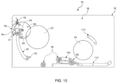
- the dispenser 10 also includes one or more rollers 90 situated along the bottom of the housing interior 16 for facilitating movement of the roll of material 20 from the first dispensing position 22 to a second dispensing position 24.
- the dispenser 10 also includes a ramp 100 having a ramp opening 102. Material from the roll of material 20 may be dispensed through the ramp opening 102.
- the ramp 100 can be located between one or more rollers 90.
- the ramp opening 102 can also be positioned above the housing access opening 120 such that the product can be dispensed from the housing access opening 120.
- the ramp 100 has a first end 104 and a second end 106.
- the first end 104 is closer in proximity to the roll of material 20 when it is in the first dispensing position 22.
- Th second end 106 of the ramp 100 is in closer proximity to the roll of material 20 when it is in the second dispensing position 24.
- the first end 104 is elevated in comparison to the second end 106 in order to facilitate movement of the roll of material 20 from the first dispensing position 22 to the second dispensing position 24.
- the dispenser 10 includes a housing access opening 120 having a housing access opening perimeter 121.
- the housing access opening 120 can have one or more tear members 122 situated about the housing access opening perimeter 121 to facilitate tearing and removal of the material product form the jumbo roll.
- the one or more tear members 122 may include serrated molded plastic teeth suitable for separating material product from the roll of material 20.
- the dispenser 10 includes a housing interior 16 capable of holding the roll of material 20 in a first dispensing position 22 and a second dispensing position 24.
- the dispenser of Fig. 10 is empty and does not have a roll of material 20 inserted therein.
- Figs. 10-17 illustrate the movement of a roll of material 20 from the first dispensing position 22 to the second dispensing position 24.
- Fig. 11 when restroom personnel load a new roll of material into the dispenser 10 they must move the transfer arm 50 fully in the direction of Arrow X, which stretches the extension spring 82 and allows the transfer latch 70 to engage the notch 65 of the transfer disk 60, thus locking the transfer disk 60 in place and storing energy in the extension spring 82.
- a portion of the roll of material 20 may rest on one or more rollers 90 in order to assist removal of product from the roll of material 20.
- the roll of material 20 generally has a diameter "D" that decreases as product is removed from the roll.
- the transfer arm roller 53 is also in contact with the roll of material 20 when it is in the first dispensing position.
- the extension spring 82 can return its stored energy to the transfer apparatus system thus rotating the transfer disk 60 to the extent permitted by the transfer disk protrusion 68 and the transfer disk control slot 84.
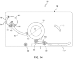
- the release of the extension spring 82 forces the transfer arm 50 against the partially depleted roll of material 20, thus driving the roll of material 20 up, onto and over the ramp 100, as shown in Figs. 13-14 .
- the dispenser 10 also includes a stub roll support base 110 and an upper stub roll support member 112 configured to engage and secure the roll of material 20 in the second dispensing position 24.
- the edges of the ramp 100 function to prevent the roll of material 20 in a second dispensing position 24 from being pulled off the stub roll supports, including the stub roll support base 110 and the upper stub roll support member 112.
- the roll of material 20 generally has a diameter as shown by "D".
- the initial diameter "D" of a full, unused from may be from about 15 cm to about 35 cm, such as from about 17 cm to about 32 cm.
- the roll transfer apparatus facilitates movement of the roll of material 20 from the first dispensing position 22 to the second dispensing position 24.
- the transfer diameter may range from about 5 cm to about 25 cm, such as from about 10 cm to about 17 cm.
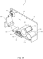
- the dispenser 10 may also include a rearward section 150 that defines an opening or a space sufficient to allow an empty core 155 from the roll of material 20 to pass by and be stored in the rearward section 150 until such time as the service personnel arrives to service the dispenser 10.
- the roll of material 20 can include a sheet of material or sheets of material that are wound around a core, such as paperboard core.
- the dispenser 10, is capable of automatically moving the roll of material 20 from the first dispensing position 22 to the second dispensing position 24. It is contemplated, that restroom personnel can insert a fresh or new roll of material 20 in a first dispensing position 22 without removing the remaining roll of material located in the second dispensing position 24.
- the roll transfer apparatus 40 will move the material roll into the second dispensing position 24 and the fully used core currently occupying the second dispensing position will be pushed into the rearward section 150 so that the roll of material can be utilized in the second dispensing position 24.
- the remaining core of a completely used roll of material will not impede another roll of material from moving from the first dispensing position 22 to the second dispensing position 24.
- One or more fasteners can be used to secure the rear housing 12 to the mounting surface, such as the interior wall of a restroom stall.
- the backplate 18 of the rear housing 12 can include one or more openings configured to receive a fastener for securing the rear housing 12 to the mounting surface.
- the fastener can include any hardware device that mechanically joins affixes two or more objects together.
- the fastener(s) can be used to join the rear housing 12 to the mounting surface to a bracket located on the mounting surface.
- the fastener(s) can include those that are able to create non-permanent joints, that is, the joint can be removed or dismantled without damaging the joined components.
- the fastener(s) selected can be used to removably join the rear housing 12 to the mounting surface.
- Any suitable fastener can be used.
- Suitable fasteners include, but are not limited to, anchors, bolts, nails, nuts, pins, clips rivets, rods, screws, clamps, washers, and combinations thereof.
- the fastener(s) includes a screw.
- the present dispenser 10 can be used to hold any material stored on or dispensed from a roll, including but not limited to toilet paper, paper towels, hand towels, plastic materials etc.
- the roll of material includes a jumbo roll of toilet paper or toilet tissue. While in many embodiments, the roll of material will include a core, it is contemplated that the present disclosure can also be used with coreless products or small core products.
- Also provided is a method for replacing a roll of material or for inserting a roll of material into a dispenser including accessing the housing interior, placing a roll of material in the first dispensing position, removing a partially used roll of material (i.e. stub roll) or the core from a fully used roll of material from the second position, and securing the openable cover to the rear housing.
- the method further includes placing the roll of material on the transfer arm roller and moving transfer arm such that the hook of the transfer latch engages the notch of the transfer disk.
Landscapes
- Health & Medical Sciences (AREA)
- Public Health (AREA)
- Details Of Rigid Or Semi-Rigid Containers (AREA)
- Adhesive Tape Dispensing Devices (AREA)
- Replacement Of Web Rolls (AREA)
- Toilet Supplies (AREA)
Claims (15)
- Distributeur (10) pour distribuer une bobine (20) de matériau, le distributeur comprenant :un boîtier comprenant un boîtier arrière (12) et un couvercle ouvrable (14) définissant un intérieur de boîtier configuré pour recevoir un rouleau de matériau ayant un diamètre, le boîtier arrière ayant une plaque arrière (18) configurée pour être montée sur une surface de montage, dans lequel l'intérieur de boîtier est configuré pour recevoir et maintenir un rouleau de matériau dans une première position de distribution et une deuxième position de distribution ;un appareil de transfert de rouleau (40) comprenant un bras de transfert (50) configuré pour maintenir le rouleau de matériau dans la première position de distribution, dans lequel le bras de transfert comprend une première extrémité (52) ayant un cylindre de bras de transfert (53) configuré pour mettre en prise le rouleau de matériau et une deuxième extrémité (54) venant en prise avec un disque de transfert (60), etun loquet de transfert (70) ayant une première extrémité (72) configurée pour mettre en prise de manière libérable le disque de transfert ;dans lequel lorsque le diamètre du rouleau de matériau atteint une taille de diamètre de transfert, la deuxième extrémité (54) du bras de transfert (50) vient en prise avec le loquet de transfert (70) de sorte que la première extrémité (72) du loquet de transfert s'ôte de la prise avec le disque de transfert (60) pour faciliter le déplacement du rouleau de matériau de la première position de distribution à la deuxième position de distribution.
- Distributeur selon la revendication 1, dans lequel la deuxième extrémité du bras de transfert comprend un pivot de bras de transfert ayant un ressort de torsion de bras de transfert configuré avec celui-ci pour permettre le mouvement du bras de transfert autour du pivot lorsque le diamètre du rouleau de matériau change.
- Distributeur selon la revendication 1, dans lequel un premier côté du disque de transfert comprend un support ayant une surface de mise en prise de bras de transfert configurée pour mettre en prise une surface du bras de transfert et une surface de mise en prise de bobine mère configurée pour mettre en prise la bobine mère lorsqu'elle est dans la première position de distribution.
- Distributeur selon la revendication 1, dans lequel la première extrémité du loquet de transfert comprend un mécanisme de mise en prise de disque de transfert.
- Distributeur selon la revendication 4, dans lequel le mécanisme de mise en prise de disque de transfert comprend un crochet.
- Distributeur selon la revendication 5, dans lequel le disque de transfert comprend une encoche, dans lequel l'encoche est configurée pour solidement mettre en prise le crochet lorsque le rouleau de matériau est dans la première position de distribution.
- Distributeur selon la revendication 1, dans lequel le disque de transfert comprend un deuxième côté faisant face à la plaque arrière, dans lequel le deuxième côté du disque de transfert comprend un mécanisme de mise en prise de ressort configuré pour être arrimé à un ressort d'extension situé sur une portion évidée d'un côté arrière de la plaque arrière, dans lequel en outre le deuxième côté du disque de transfert comprend une saillie de disque de transfert configurée pour mettre en prise une fente de commande de disque de transfert située dans la plaque arrière.
- Distributeur selon la revendication 6, dans lequel, lorsque le crochet s'ôte de la prise avec l'encoche, le ressort d'extension est configuré pour faire tourner le disque de transfert jusqu'à une étendue permise par la fente de commande de disque de transfert pour forcer le cylindre du bras de transfert contre le rouleau de matériau afin de faciliter le mouvement du rouleau de matériau de la première position de distribution à la deuxième position de distribution.
- Distributeur selon la revendication 1, dans lequel le distributeur comprend en outre un ou plusieurs cylindres configurés pour faciliter le mouvement du rouleau de matériau de la première position à la deuxième position.
- Distributeur selon la revendication 9, dans lequel le distributeur comprend en outre une rampe située entre les un ou plusieurs cylindres, la rampe ayant une ouverture configurée pour permettre la distribution de matériau à partir du rouleau de matériau ; facultativement dans lequel la rampe a une première extrémité située plus près du rouleau de matériau dans la première position de distribution et une deuxième extrémité située plus près du rouleau de matériau dans la deuxième position de distribution, dans lequel la première extrémité est surélevée comparativement à la deuxième extrémité pour faciliter le mouvement du rouleau de matériau de la première position de distribution à la deuxième position de distribution.
- Distributeur selon la revendication 1, comprenant en outre une base de support de fin de bobine et un organe supérieur de support de fin de bobine configuré pour maintenir le rouleau de matériau dans la deuxième position de distribution ; ou dans lequel la plaque arrière comprend un premier côté faisant face à l'intérieur de boîtier et un deuxième côté faisant face à la surface de montage, dans lequel le loquet de transfert et le disque de transfert sont configurés pour être solidement fixés au premier côté de la plaque arrière.
- Distributeur selon la revendication 1, dans lequel le boîtier comprend une ouverture d'accès configurée pour permettre à un utilisateur d'accéder à une feuille de matériau à partir du rouleau de matériau ; facultativement dans lequel l'ouverture d'accès a un périmètre, dans lequel un ou plusieurs organes de déchirement s'étendent le long d'au moins une portion du périmètre.
- Distributeur selon la revendication 1, dans lequel le distributeur comprend un mécanisme de verrouillage pour verrouiller le couvercle ouvrable sur le boîtier arrière ; ou dans lequel le couvercle ouvrable est fixé de manière articulée au boîtier arrière ; ou comprenant en outre une section vers l'arrière configurée pour maintenir un mandrin vide du rouleau de matériau ; ou dans lequel le rouleau de matériau comprend un maxi rouleau de papier toilette ; ou dans lequel la taille du diamètre de transfert est d'environ 10 cm à environ 17 cm.
- Procédé pour remplacer un rouleau de matériau du distributeur selon la revendication 1, comprenant :l'accès à l'intérieur de boîtier ;le placement d'un rouleau de matériau (20) dans la première position de distribution ; le retrait d'un rouleau de matériau partiellement utilisé ou d'un mandrin d'un rouleau de matériau complètement utilisé de la deuxième position ; etl'arrimage du couvercle ouvrable (14) au boîtier arrière.
- Procédé selon la revendication 14, dans lequel le placement d'un rouleau de matériau dans la première position de distribution comprend le placement du rouleau de matériau sur le cylindre de bras de transfert et la rotation du disque de transfert de telle sorte qu'un crochet du loquet de transfert vient en prise avec une encoche du disque de transfert.
Applications Claiming Priority (1)
| Application Number | Priority Date | Filing Date | Title |
|---|---|---|---|
| PCT/US2020/070003 WO2021216138A1 (fr) | 2020-04-21 | 2020-04-21 | Distributeur à transfert mécanique et procédé |
Publications (3)
| Publication Number | Publication Date |
|---|---|
| EP4138622A1 EP4138622A1 (fr) | 2023-03-01 |
| EP4138622A4 EP4138622A4 (fr) | 2024-01-24 |
| EP4138622B1 true EP4138622B1 (fr) | 2025-06-04 |
Family
ID=78269842
Family Applications (1)
| Application Number | Title | Priority Date | Filing Date |
|---|---|---|---|
| EP20931719.7A Active EP4138622B1 (fr) | 2020-04-21 | 2020-04-21 | Distributeur à transfert mécanique et procédé |
Country Status (8)
| Country | Link |
|---|---|
| US (1) | US11337567B2 (fr) |
| EP (1) | EP4138622B1 (fr) |
| KR (1) | KR102802873B1 (fr) |
| CN (1) | CN115484855A (fr) |
| AU (1) | AU2020443633A1 (fr) |
| CA (1) | CA3176327A1 (fr) |
| MX (1) | MX2022013211A (fr) |
| WO (1) | WO2021216138A1 (fr) |
Families Citing this family (2)
| Publication number | Priority date | Publication date | Assignee | Title |
|---|---|---|---|---|
| USD995140S1 (en) | 2020-06-22 | 2023-08-15 | Kimberly-Clark Worldwide, Inc. | Paper product dispenser |
| CN115697156A (zh) * | 2020-06-22 | 2023-02-03 | 金伯利-克拉克环球有限公司 | 用于卷状片材的分配器 |
Family Cites Families (44)
| Publication number | Priority date | Publication date | Assignee | Title |
|---|---|---|---|---|
| US2288332A (en) * | 1939-05-24 | 1942-06-30 | Steiner Sales Co | Dispensing cabinet and method of servicing |
| US3084006A (en) * | 1960-06-13 | 1963-04-02 | Crown Zellerbach Corp | Two-roll paper dispenser |
| US4203562A (en) * | 1977-09-08 | 1980-05-20 | Georgia-Pacific Corporation | Flexible sheet material dispensing of rolls in succession |
| US4307639A (en) * | 1978-04-18 | 1981-12-29 | Georgia-Pacific Corporation | Multiple wound roll dispenser for flexible sheet material |
| US4307638A (en) * | 1978-05-22 | 1981-12-29 | Georgia-Pacific Corporation | Method of dispersing flexible sheet material |
| GB2028765B (en) * | 1978-08-10 | 1983-02-16 | Latz P | Paper an other sheet material roll dispenser |
| US4403748A (en) * | 1981-08-27 | 1983-09-13 | Griffith-Hope Company | Dispenser for coiled material having improved transfer mechanism |
| IL67028A (en) * | 1982-10-20 | 1986-03-31 | Shpigelman David | Dispensing device for cylindrical bodies,such as rolls of toilet paper and paper towels |
| FR2587013B2 (fr) * | 1985-06-20 | 1987-12-31 | Granger Maurice | Appareil simplifie de distribution et de coupe simultanee de bandes de materiaux enroules, avec changement automatique du rouleau en service |
| FR2599726B1 (fr) | 1986-06-09 | 1989-04-21 | Granger Maurice | Appareil distributeur de longueurs de materiaux enroules sur un noyau, avec dispositif de remplacement automatique du rouleau en service, par un rouleau de reserve |
| US5172840A (en) * | 1990-03-19 | 1992-12-22 | Bloch Nathan D | Dispensing apparatus for primary and remnant rolls of toilet tissue |
| US5271574A (en) * | 1991-08-28 | 1993-12-21 | Georgia-Pacific Corporation | Dispenser for flexible sheet material |
| US5314131A (en) * | 1993-01-04 | 1994-05-24 | Georgia-Pacific Corporation | Apparatus for dispensing rolled flexible sheet material |
| WO1995023677A1 (fr) * | 1994-03-04 | 1995-09-08 | Scott Paper Company | Appareil permettant de derouler et de couper une bande enroulee |
| US5558302A (en) * | 1995-02-07 | 1996-09-24 | Georgia-Pacific Corporation | Flexible sheet material dispenser with automatic roll transferring mechanism |
| US5979822A (en) | 1998-09-30 | 1999-11-09 | Perrin Manufacturing Company | Apparatus for dispensing sheet material from a roll of sheet material |
| US6224010B1 (en) * | 1998-01-22 | 2001-05-01 | Perrin Manufacturing Company | Apparatus and method for dispensing paper toweling from a roll of paper toweling |
| US6302351B1 (en) * | 1998-02-27 | 2001-10-16 | The Colman Group, Inc. | Dispenser for multiple rolls of sheet material |
| FR2779049B1 (fr) * | 1998-05-27 | 2000-06-30 | Maurice Granger | Dispositif d'introduction d'une bande de materiau dans un appareil distributeur de materiaux d'essuyage |
| US6152397A (en) * | 1998-10-30 | 2000-11-28 | Kimberly-Clark Worldwide Inc. | Spacing member for a sheet material dispenser |
| US6346153B1 (en) * | 1998-12-17 | 2002-02-12 | Kimberly-Clark Worldwide, Inc. | Wet or dry web dispenser |
| US6145779A (en) | 1999-09-23 | 2000-11-14 | Kimberly-Clark Worldwide, Inc. | Dual roll transfer dispenser |
| US6592067B2 (en) * | 2001-02-09 | 2003-07-15 | Georgia-Pacific Corporation | Minimizing paper waste carousel-style dispenser apparatus, sensor, method and system with proximity sensor |
| US6684751B2 (en) * | 2001-12-13 | 2004-02-03 | Kimberly-Clark Worldwide, Inc. | Rolled web dispenser and cutting apparatus |
| US6752349B2 (en) * | 2001-12-20 | 2004-06-22 | Fort James Corporation | Support sled for rolls of absorbent sheet and dispenser incorporating same |
| GB2400362A (en) | 2003-04-11 | 2004-10-13 | Englewood Ventures Inc | A dispenser for rolls of toilet paper. |
| FR2868407B1 (fr) * | 2004-04-01 | 2021-10-01 | Maurice Granger | Embout de retenue pour bobine de materiau d'essuyage sur un appareil distributeur de materiau d'essuyage |
| FR2870703B1 (fr) * | 2004-05-28 | 2006-07-07 | Maurice Granger | Dispositif de controle anti-boucles pour appareil distributeur automatique de materiaux d'essuyage |
| TR201807570T4 (tr) * | 2006-07-07 | 2018-06-21 | Sca Hygiene Prod Ab | Tabaka formundaki ürünlere yönelik dağıtıcı. |
| US7967235B2 (en) * | 2006-10-03 | 2011-06-28 | Sca Tissue North America Llc | Dispenser that automatically transfers rolls of absorbent material, method of reloading same, and rolls of absorbent material for use in same |
| FR2911487B1 (fr) * | 2007-01-24 | 2009-03-06 | Maurice Granger | Dispositif recepteur de bobines de materiaux d'essuyage en fin de service pour appareil distributeur de materiaux d'essuyage. |
| US7866593B2 (en) | 2008-04-28 | 2011-01-11 | Dispensing Dynamics International Ltd | Two roll drop front toilet tissue dispenser |
| AT506716B1 (de) | 2008-05-05 | 2011-05-15 | Hagleitner Hans Georg | Spender für papier |
| EP2296518B1 (fr) * | 2008-05-05 | 2017-08-23 | Hans Georg Hagleitner | Distributeur de papier |
| US8356767B2 (en) * | 2009-12-15 | 2013-01-22 | Sca Tissue North America Llc | Dispenser for multiple rolls of web material with automatic roll transfer, and method of loading same |
| US9326648B2 (en) * | 2013-06-13 | 2016-05-03 | Dispensing Dynamics International | Dispensing system for consecutively dispensing paper sheet material from a stub roll and a primary roll |
| US9854948B1 (en) * | 2015-03-31 | 2018-01-02 | Wisconsin Plastics, Inc. | Paper towel dispenser |
| US10215270B2 (en) * | 2015-09-14 | 2019-02-26 | Gpcp Ip Holdings Llc | Automated product dispensers and related methods for isolating a drive assembly to inhibit vibration transmission |
| AU2015414967B2 (en) | 2015-11-16 | 2019-05-09 | Essity Hygiene And Health Aktiebolag | Dispenser for rolls |
| CO2018007632A2 (es) | 2016-01-06 | 2018-09-20 | Essity Operations Wausau LLC | Un dispensador de productos enrollados |
| IT201800005217A1 (it) * | 2018-05-09 | 2019-11-09 | Un adattatore per un rotolo di carta e relativo dispenser ad asse girevole fornito di tale adattature | |
| CA3099743A1 (fr) * | 2018-05-16 | 2019-11-21 | Bradley Fixtures Corporation | Distributeur de serviettes en rouleaux |
| CA3052590C (fr) * | 2018-08-22 | 2024-04-09 | Cascades Canada Ulc | Distributeur de materiau sous forme de bande et ensemble d'alimentation de materiau sous forme de bande pour un distributeur de materiau sous forme de bande |
| US11406231B2 (en) * | 2019-04-26 | 2022-08-09 | Dispensing Dynamics International, Inc. | Automatic roll transfer dispenser |
-
2020
- 2020-04-21 CA CA3176327A patent/CA3176327A1/fr active Pending
- 2020-04-21 AU AU2020443633A patent/AU2020443633A1/en active Pending
- 2020-04-21 EP EP20931719.7A patent/EP4138622B1/fr active Active
- 2020-04-21 KR KR1020227039791A patent/KR102802873B1/ko active Active
- 2020-04-21 MX MX2022013211A patent/MX2022013211A/es unknown
- 2020-04-21 US US17/281,286 patent/US11337567B2/en active Active
- 2020-04-21 CN CN202080100448.4A patent/CN115484855A/zh active Pending
- 2020-04-21 WO PCT/US2020/070003 patent/WO2021216138A1/fr not_active Ceased
Also Published As
| Publication number | Publication date |
|---|---|
| US20210345840A1 (en) | 2021-11-11 |
| CN115484855A (zh) | 2022-12-16 |
| EP4138622A1 (fr) | 2023-03-01 |
| KR102802873B1 (ko) | 2025-05-07 |
| CA3176327A1 (fr) | 2021-10-28 |
| KR20230007380A (ko) | 2023-01-12 |
| AU2020443633A1 (en) | 2022-12-08 |
| US11337567B2 (en) | 2022-05-24 |
| MX2022013211A (es) | 2023-01-16 |
| WO2021216138A1 (fr) | 2021-10-28 |
| EP4138622A4 (fr) | 2024-01-24 |
Similar Documents
| Publication | Publication Date | Title |
|---|---|---|
| CA2576909C (fr) | Distributeur de rouleaux multiples de materiau en feuilles | |
| US5100075A (en) | Core removing tissue dispenser | |
| US5695065A (en) | Bag dispensers and method of dispensing bags therefrom | |
| RU2634238C1 (ru) | Раздатчик гигиенической бумаги и способ выдачи гигиенической бумаги | |
| US5509593A (en) | Combined wet and dry sanitary tissue dispenser | |
| US20080142542A1 (en) | Assembly for dispensing pre-moistened towelettes | |
| AU2001249470B2 (en) | Dispenser apparatus and method | |
| EP4138622B1 (fr) | Distributeur à transfert mécanique et procédé | |
| US5601253A (en) | Dispenser for rolled sheet material | |
| AU2001249470A1 (en) | Dispenser apparatus and method | |
| WO2004103138A1 (fr) | Distributeur pour matiere en feuille | |
| AU778009B2 (en) | Dispenser apparatus and method | |
| MXPA01003278A (es) | Aparato dispensador y metodo. | |
| EP0026241B1 (fr) | Support et distributeur pour rouleaux empilés | |
| EP4167818B1 (fr) | Distributeur de matériaux en feuilles en rouleau |
Legal Events
| Date | Code | Title | Description |
|---|---|---|---|
| STAA | Information on the status of an ep patent application or granted ep patent |
Free format text: STATUS: THE INTERNATIONAL PUBLICATION HAS BEEN MADE |
|
| PUAI | Public reference made under article 153(3) epc to a published international application that has entered the european phase |
Free format text: ORIGINAL CODE: 0009012 |
|
| STAA | Information on the status of an ep patent application or granted ep patent |
Free format text: STATUS: REQUEST FOR EXAMINATION WAS MADE |
|
| 17P | Request for examination filed |
Effective date: 20221118 |
|
| AK | Designated contracting states |
Kind code of ref document: A1 Designated state(s): AL AT BE BG CH CY CZ DE DK EE ES FI FR GB GR HR HU IE IS IT LI LT LU LV MC MK MT NL NO PL PT RO RS SE SI SK SM TR |
|
| DAV | Request for validation of the european patent (deleted) | ||
| DAX | Request for extension of the european patent (deleted) | ||
| A4 | Supplementary search report drawn up and despatched |
Effective date: 20231221 |
|
| RIC1 | Information provided on ipc code assigned before grant |
Ipc: A47K 10/38 20060101ALI20231215BHEP Ipc: A47K 10/32 20060101AFI20231215BHEP |
|
| RIN1 | Information on inventor provided before grant (corrected) |
Inventor name: LEWIS, RICHARD P. Inventor name: GODFREY, ROBERT Inventor name: WOERPEL, MATTHEW T. Inventor name: BRICKL, JEFFREY J. Inventor name: RALEIGH, EDWARD A. |
|
| GRAP | Despatch of communication of intention to grant a patent |
Free format text: ORIGINAL CODE: EPIDOSNIGR1 |
|
| STAA | Information on the status of an ep patent application or granted ep patent |
Free format text: STATUS: GRANT OF PATENT IS INTENDED |
|
| INTG | Intention to grant announced |
Effective date: 20241125 |
|
| GRAS | Grant fee paid |
Free format text: ORIGINAL CODE: EPIDOSNIGR3 |
|
| RAP3 | Party data changed (applicant data changed or rights of an application transferred) |
Owner name: KIMBERLY-CLARK WORLDWIDE, INC. |
|
| GRAA | (expected) grant |
Free format text: ORIGINAL CODE: 0009210 |
|
| STAA | Information on the status of an ep patent application or granted ep patent |
Free format text: STATUS: THE PATENT HAS BEEN GRANTED |
|
| P01 | Opt-out of the competence of the unified patent court (upc) registered |
Free format text: CASE NUMBER: APP_15547/2025 Effective date: 20250331 |
|
| AK | Designated contracting states |
Kind code of ref document: B1 Designated state(s): AL AT BE BG CH CY CZ DE DK EE ES FI FR GB GR HR HU IE IS IT LI LT LU LV MC MK MT NL NO PL PT RO RS SE SI SK SM TR |
|
| REG | Reference to a national code |
Ref country code: GB Ref legal event code: FG4D |
|
| REG | Reference to a national code |
Ref country code: CH Ref legal event code: EP |
|
| REG | Reference to a national code |
Ref country code: DE Ref legal event code: R096 Ref document number: 602020052490 Country of ref document: DE |
|
| REG | Reference to a national code |
Ref country code: IE Ref legal event code: FG4D |
|
| REG | Reference to a national code |
Ref country code: NL Ref legal event code: MP Effective date: 20250604 |
|
| PG25 | Lapsed in a contracting state [announced via postgrant information from national office to epo] |
Ref country code: FI Free format text: LAPSE BECAUSE OF FAILURE TO SUBMIT A TRANSLATION OF THE DESCRIPTION OR TO PAY THE FEE WITHIN THE PRESCRIBED TIME-LIMIT Effective date: 20250604 Ref country code: ES Free format text: LAPSE BECAUSE OF FAILURE TO SUBMIT A TRANSLATION OF THE DESCRIPTION OR TO PAY THE FEE WITHIN THE PRESCRIBED TIME-LIMIT Effective date: 20250604 |
|
| REG | Reference to a national code |
Ref country code: LT Ref legal event code: MG9D |
|
| PG25 | Lapsed in a contracting state [announced via postgrant information from national office to epo] |
Ref country code: GR Free format text: LAPSE BECAUSE OF FAILURE TO SUBMIT A TRANSLATION OF THE DESCRIPTION OR TO PAY THE FEE WITHIN THE PRESCRIBED TIME-LIMIT Effective date: 20250905 Ref country code: NO Free format text: LAPSE BECAUSE OF FAILURE TO SUBMIT A TRANSLATION OF THE DESCRIPTION OR TO PAY THE FEE WITHIN THE PRESCRIBED TIME-LIMIT Effective date: 20250904 |
|
| PG25 | Lapsed in a contracting state [announced via postgrant information from national office to epo] |
Ref country code: PL Free format text: LAPSE BECAUSE OF FAILURE TO SUBMIT A TRANSLATION OF THE DESCRIPTION OR TO PAY THE FEE WITHIN THE PRESCRIBED TIME-LIMIT Effective date: 20250604 |
|
| PG25 | Lapsed in a contracting state [announced via postgrant information from national office to epo] |
Ref country code: BG Free format text: LAPSE BECAUSE OF FAILURE TO SUBMIT A TRANSLATION OF THE DESCRIPTION OR TO PAY THE FEE WITHIN THE PRESCRIBED TIME-LIMIT Effective date: 20250604 |
|
| PG25 | Lapsed in a contracting state [announced via postgrant information from national office to epo] |
Ref country code: HR Free format text: LAPSE BECAUSE OF FAILURE TO SUBMIT A TRANSLATION OF THE DESCRIPTION OR TO PAY THE FEE WITHIN THE PRESCRIBED TIME-LIMIT Effective date: 20250604 |
|
| PG25 | Lapsed in a contracting state [announced via postgrant information from national office to epo] |
Ref country code: RS Free format text: LAPSE BECAUSE OF FAILURE TO SUBMIT A TRANSLATION OF THE DESCRIPTION OR TO PAY THE FEE WITHIN THE PRESCRIBED TIME-LIMIT Effective date: 20250904 |
|
| PG25 | Lapsed in a contracting state [announced via postgrant information from national office to epo] |
Ref country code: LV Free format text: LAPSE BECAUSE OF FAILURE TO SUBMIT A TRANSLATION OF THE DESCRIPTION OR TO PAY THE FEE WITHIN THE PRESCRIBED TIME-LIMIT Effective date: 20250604 |
|
| PG25 | Lapsed in a contracting state [announced via postgrant information from national office to epo] |
Ref country code: NL Free format text: LAPSE BECAUSE OF FAILURE TO SUBMIT A TRANSLATION OF THE DESCRIPTION OR TO PAY THE FEE WITHIN THE PRESCRIBED TIME-LIMIT Effective date: 20250604 |
|
| PG25 | Lapsed in a contracting state [announced via postgrant information from national office to epo] |
Ref country code: PT Free format text: LAPSE BECAUSE OF FAILURE TO SUBMIT A TRANSLATION OF THE DESCRIPTION OR TO PAY THE FEE WITHIN THE PRESCRIBED TIME-LIMIT Effective date: 20251006 |
|
| REG | Reference to a national code |
Ref country code: AT Ref legal event code: MK05 Ref document number: 1799504 Country of ref document: AT Kind code of ref document: T Effective date: 20250604 |
|
| PG25 | Lapsed in a contracting state [announced via postgrant information from national office to epo] |
Ref country code: IS Free format text: LAPSE BECAUSE OF FAILURE TO SUBMIT A TRANSLATION OF THE DESCRIPTION OR TO PAY THE FEE WITHIN THE PRESCRIBED TIME-LIMIT Effective date: 20251004 |
|
| PG25 | Lapsed in a contracting state [announced via postgrant information from national office to epo] |
Ref country code: AT Free format text: LAPSE BECAUSE OF FAILURE TO SUBMIT A TRANSLATION OF THE DESCRIPTION OR TO PAY THE FEE WITHIN THE PRESCRIBED TIME-LIMIT Effective date: 20250604 Ref country code: SM Free format text: LAPSE BECAUSE OF FAILURE TO SUBMIT A TRANSLATION OF THE DESCRIPTION OR TO PAY THE FEE WITHIN THE PRESCRIBED TIME-LIMIT Effective date: 20250604 |
|
| PG25 | Lapsed in a contracting state [announced via postgrant information from national office to epo] |
Ref country code: CZ Free format text: LAPSE BECAUSE OF FAILURE TO SUBMIT A TRANSLATION OF THE DESCRIPTION OR TO PAY THE FEE WITHIN THE PRESCRIBED TIME-LIMIT Effective date: 20250604 |
|
| PG25 | Lapsed in a contracting state [announced via postgrant information from national office to epo] |
Ref country code: EE Free format text: LAPSE BECAUSE OF FAILURE TO SUBMIT A TRANSLATION OF THE DESCRIPTION OR TO PAY THE FEE WITHIN THE PRESCRIBED TIME-LIMIT Effective date: 20250604 |
|
| PG25 | Lapsed in a contracting state [announced via postgrant information from national office to epo] |
Ref country code: SK Free format text: LAPSE BECAUSE OF FAILURE TO SUBMIT A TRANSLATION OF THE DESCRIPTION OR TO PAY THE FEE WITHIN THE PRESCRIBED TIME-LIMIT Effective date: 20250604 |
|
| PG25 | Lapsed in a contracting state [announced via postgrant information from national office to epo] |
Ref country code: IT Free format text: LAPSE BECAUSE OF FAILURE TO SUBMIT A TRANSLATION OF THE DESCRIPTION OR TO PAY THE FEE WITHIN THE PRESCRIBED TIME-LIMIT Effective date: 20250604 |
|
| REG | Reference to a national code |
Ref country code: DE Ref legal event code: R097 Ref document number: 602020052490 Country of ref document: DE |
|
| PLBE | No opposition filed within time limit |
Free format text: ORIGINAL CODE: 0009261 |
|
| STAA | Information on the status of an ep patent application or granted ep patent |
Free format text: STATUS: NO OPPOSITION FILED WITHIN TIME LIMIT |
|
| PG25 | Lapsed in a contracting state [announced via postgrant information from national office to epo] |
Ref country code: DK Free format text: LAPSE BECAUSE OF FAILURE TO SUBMIT A TRANSLATION OF THE DESCRIPTION OR TO PAY THE FEE WITHIN THE PRESCRIBED TIME-LIMIT Effective date: 20250604 |
|
| REG | Reference to a national code |
Ref country code: CH Ref legal event code: L10 Free format text: ST27 STATUS EVENT CODE: U-0-0-L10-L00 (AS PROVIDED BY THE NATIONAL OFFICE) Effective date: 20260416 |