EP4139067B1 - Innenhochdruckumformverfahren zur herstellung von wärmerohrdochten - Google Patents
Innenhochdruckumformverfahren zur herstellung von wärmerohrdochten Download PDFInfo
- Publication number
- EP4139067B1 EP4139067B1 EP21724469.8A EP21724469A EP4139067B1 EP 4139067 B1 EP4139067 B1 EP 4139067B1 EP 21724469 A EP21724469 A EP 21724469A EP 4139067 B1 EP4139067 B1 EP 4139067B1
- Authority
- EP
- European Patent Office
- Prior art keywords
- wick
- tube
- forming
- assembly
- forming shell
- Prior art date
- Legal status (The legal status is an assumption and is not a legal conclusion. Google has not performed a legal analysis and makes no representation as to the accuracy of the status listed.)
- Active
Links
Images


Classifications
-
- B—PERFORMING OPERATIONS; TRANSPORTING
- B21—MECHANICAL METAL-WORKING WITHOUT ESSENTIALLY REMOVING MATERIAL; PUNCHING METAL
- B21D—WORKING OR PROCESSING OF SHEET METAL OR METAL TUBES, RODS OR PROFILES WITHOUT ESSENTIALLY REMOVING MATERIAL; PUNCHING METAL
- B21D26/00—Shaping without cutting otherwise than using rigid devices or tools or yieldable or resilient pads, i.e. applying fluid pressure or magnetic forces
- B21D26/02—Shaping without cutting otherwise than using rigid devices or tools or yieldable or resilient pads, i.e. applying fluid pressure or magnetic forces by applying fluid pressure
- B21D26/033—Deforming tubular bodies
-
- B—PERFORMING OPERATIONS; TRANSPORTING
- B29—WORKING OF PLASTICS; WORKING OF SUBSTANCES IN A PLASTIC STATE IN GENERAL
- B29C—SHAPING OR JOINING OF PLASTICS; SHAPING OF MATERIAL IN A PLASTIC STATE, NOT OTHERWISE PROVIDED FOR; AFTER-TREATMENT OF THE SHAPED PRODUCTS, e.g. REPAIRING
- B29C43/00—Compression moulding, i.e. applying external pressure to flow the moulding material; Apparatus therefor
- B29C43/02—Compression moulding, i.e. applying external pressure to flow the moulding material; Apparatus therefor of articles of definite length, i.e. discrete articles
- B29C43/10—Isostatic pressing, i.e. using non-rigid pressure-exerting members against rigid parts or dies
-
- B—PERFORMING OPERATIONS; TRANSPORTING
- B21—MECHANICAL METAL-WORKING WITHOUT ESSENTIALLY REMOVING MATERIAL; PUNCHING METAL
- B21D—WORKING OR PROCESSING OF SHEET METAL OR METAL TUBES, RODS OR PROFILES WITHOUT ESSENTIALLY REMOVING MATERIAL; PUNCHING METAL
- B21D39/00—Application of procedures in order to connect objects or parts, e.g. coating with sheet metal otherwise than by plating; Tube expanders
- B21D39/04—Application of procedures in order to connect objects or parts, e.g. coating with sheet metal otherwise than by plating; Tube expanders of tubes with tubes; of tubes with rods
-
- B—PERFORMING OPERATIONS; TRANSPORTING
- B21—MECHANICAL METAL-WORKING WITHOUT ESSENTIALLY REMOVING MATERIAL; PUNCHING METAL
- B21D—WORKING OR PROCESSING OF SHEET METAL OR METAL TUBES, RODS OR PROFILES WITHOUT ESSENTIALLY REMOVING MATERIAL; PUNCHING METAL
- B21D53/00—Making other particular articles
- B21D53/02—Making other particular articles heat exchangers or parts thereof, e.g. radiators, condensers fins, headers
- B21D53/06—Making other particular articles heat exchangers or parts thereof, e.g. radiators, condensers fins, headers of metal tubes
-
- B—PERFORMING OPERATIONS; TRANSPORTING
- B29—WORKING OF PLASTICS; WORKING OF SUBSTANCES IN A PLASTIC STATE IN GENERAL
- B29C—SHAPING OR JOINING OF PLASTICS; SHAPING OF MATERIAL IN A PLASTIC STATE, NOT OTHERWISE PROVIDED FOR; AFTER-TREATMENT OF THE SHAPED PRODUCTS, e.g. REPAIRING
- B29C43/00—Compression moulding, i.e. applying external pressure to flow the moulding material; Apparatus therefor
- B29C43/32—Component parts, details or accessories; Auxiliary operations
- B29C43/36—Moulds for making articles of definite length, i.e. discrete articles
- B29C43/3642—Bags, bleeder sheets or cauls for isostatic pressing
-
- F—MECHANICAL ENGINEERING; LIGHTING; HEATING; WEAPONS; BLASTING
- F28—HEAT EXCHANGE IN GENERAL
- F28D—HEAT-EXCHANGE APPARATUS, NOT PROVIDED FOR IN ANOTHER SUBCLASS, IN WHICH THE HEAT-EXCHANGE MEDIA DO NOT COME INTO DIRECT CONTACT
- F28D15/00—Heat-exchange apparatus with the intermediate heat-transfer medium in closed tubes passing into or through the conduit walls ; Heat-exchange apparatus employing intermediate heat-transfer medium or bodies
- F28D15/02—Heat-exchange apparatus with the intermediate heat-transfer medium in closed tubes passing into or through the conduit walls ; Heat-exchange apparatus employing intermediate heat-transfer medium or bodies in which the medium condenses and evaporates, e.g. heat pipes
- F28D15/04—Heat-exchange apparatus with the intermediate heat-transfer medium in closed tubes passing into or through the conduit walls ; Heat-exchange apparatus employing intermediate heat-transfer medium or bodies in which the medium condenses and evaporates, e.g. heat pipes with tubes having a capillary structure
-
- F—MECHANICAL ENGINEERING; LIGHTING; HEATING; WEAPONS; BLASTING
- F28—HEAT EXCHANGE IN GENERAL
- F28D—HEAT-EXCHANGE APPARATUS, NOT PROVIDED FOR IN ANOTHER SUBCLASS, IN WHICH THE HEAT-EXCHANGE MEDIA DO NOT COME INTO DIRECT CONTACT
- F28D15/00—Heat-exchange apparatus with the intermediate heat-transfer medium in closed tubes passing into or through the conduit walls ; Heat-exchange apparatus employing intermediate heat-transfer medium or bodies
- F28D15/02—Heat-exchange apparatus with the intermediate heat-transfer medium in closed tubes passing into or through the conduit walls ; Heat-exchange apparatus employing intermediate heat-transfer medium or bodies in which the medium condenses and evaporates, e.g. heat pipes
- F28D15/04—Heat-exchange apparatus with the intermediate heat-transfer medium in closed tubes passing into or through the conduit walls ; Heat-exchange apparatus employing intermediate heat-transfer medium or bodies in which the medium condenses and evaporates, e.g. heat pipes with tubes having a capillary structure
- F28D15/046—Heat-exchange apparatus with the intermediate heat-transfer medium in closed tubes passing into or through the conduit walls ; Heat-exchange apparatus employing intermediate heat-transfer medium or bodies in which the medium condenses and evaporates, e.g. heat pipes with tubes having a capillary structure characterised by the material or the construction of the capillary structure
-
- B—PERFORMING OPERATIONS; TRANSPORTING
- B29—WORKING OF PLASTICS; WORKING OF SUBSTANCES IN A PLASTIC STATE IN GENERAL
- B29C—SHAPING OR JOINING OF PLASTICS; SHAPING OF MATERIAL IN A PLASTIC STATE, NOT OTHERWISE PROVIDED FOR; AFTER-TREATMENT OF THE SHAPED PRODUCTS, e.g. REPAIRING
- B29C43/00—Compression moulding, i.e. applying external pressure to flow the moulding material; Apparatus therefor
- B29C43/32—Component parts, details or accessories; Auxiliary operations
- B29C43/36—Moulds for making articles of definite length, i.e. discrete articles
- B29C2043/3602—Moulds for making articles of definite length, i.e. discrete articles with means for positioning, fastening or clamping the material to be formed or preforms inside the mould
-
- B—PERFORMING OPERATIONS; TRANSPORTING
- B29—WORKING OF PLASTICS; WORKING OF SUBSTANCES IN A PLASTIC STATE IN GENERAL
- B29C—SHAPING OR JOINING OF PLASTICS; SHAPING OF MATERIAL IN A PLASTIC STATE, NOT OTHERWISE PROVIDED FOR; AFTER-TREATMENT OF THE SHAPED PRODUCTS, e.g. REPAIRING
- B29C43/00—Compression moulding, i.e. applying external pressure to flow the moulding material; Apparatus therefor
- B29C43/32—Component parts, details or accessories; Auxiliary operations
- B29C43/36—Moulds for making articles of definite length, i.e. discrete articles
- B29C43/3642—Bags, bleeder sheets or cauls for isostatic pressing
- B29C2043/3649—Inflatable bladders using gas or fluid and related details
-
- B—PERFORMING OPERATIONS; TRANSPORTING
- B29—WORKING OF PLASTICS; WORKING OF SUBSTANCES IN A PLASTIC STATE IN GENERAL
- B29L—INDEXING SCHEME ASSOCIATED WITH SUBCLASS B29C, RELATING TO PARTICULAR ARTICLES
- B29L2031/00—Other particular articles
- B29L2031/18—Heat-exchangers or parts thereof
-
- F—MECHANICAL ENGINEERING; LIGHTING; HEATING; WEAPONS; BLASTING
- F28—HEAT EXCHANGE IN GENERAL
- F28F—DETAILS OF HEAT-EXCHANGE AND HEAT-TRANSFER APPARATUS, OF GENERAL APPLICATION
- F28F2275/00—Fastening; Joining
- F28F2275/12—Fastening; Joining by methods involving deformation of the elements
- F28F2275/125—Fastening; Joining by methods involving deformation of the elements by bringing elements together and expanding
-
- Y—GENERAL TAGGING OF NEW TECHNOLOGICAL DEVELOPMENTS; GENERAL TAGGING OF CROSS-SECTIONAL TECHNOLOGIES SPANNING OVER SEVERAL SECTIONS OF THE IPC; TECHNICAL SUBJECTS COVERED BY FORMER USPC CROSS-REFERENCE ART COLLECTIONS [XRACs] AND DIGESTS
- Y02—TECHNOLOGIES OR APPLICATIONS FOR MITIGATION OR ADAPTATION AGAINST CLIMATE CHANGE
- Y02E—REDUCTION OF GREENHOUSE GAS [GHG] EMISSIONS, RELATED TO ENERGY GENERATION, TRANSMISSION OR DISTRIBUTION
- Y02E30/00—Energy generation of nuclear origin
- Y02E30/30—Nuclear fission reactors
Definitions
- This invention relates generally to heat pipes used in heat transfer systems, and more particularly, to wicks within the heat pipes that are configured to transfer the working fluid of the heat pipe from a condenser region of the heat pipe to an evaporator region.
- a heat pipe is a hermetically sealed, two-phase heat transfer component used to transfer heat from a primary side (evaporator section) to a secondary side (condenser section).
- FIG. 1 illustrates a heat pipe 100 comprising the aforementioned evaporator section 102 and condenser section 106, along with an adiabatic section 104 extending therebetween.
- the heat pipe 100 further includes a working fluid (such as water, liquid potassium, sodium, or alkali metal) and a wick 108.
- the working fluid is configured to absorb heat in the evaporator section 102 and vaporize.
- the saturated vapor, carrying latent heat of vaporization flows towards the condenser section 106 through the adiabatic section 104.
- the vapor condenses into a liquid pool 110 and gives off its latent heat.
- the condensed liquid is then returned to the evaporator section 102 through the wick 108 by capillary action.
- the aforementioned flow path of the working fluid is illustrated by segmented arrows in FIG. 1 .
- the phase change processes and two-phase flow circulation continues as long as the temperature gradient between the evaporator and condenser sections is maintained. Due to the very high heat transfer coefficients for boiling and condensation, heat pipes are highly effective thermal conductors.
- heat pipes are utilized by placing the evaporator section of the heat pipe within the reactor core containing nuclear fuel and the condenser section is placed near heat exchangers.
- the nuclear fuel vaporizes the working fluid and heat exchangers absorb the latent heat at the condenser section.
- Example heat pipes in nuclear applications are described in U.S. Patent No. 5,684,848 , U.S. Patent No. 6,768,781 , and U.S. Patent Application Publication No. 2016/0027536 .
- micro-reactors are nuclear reactors that generate less than 10MWe and are capable of being deployed for remote applications. These micro-reactors can be packaged in relatively small containers, operate without active involvement of personnel, and operate without refueling/replacement for a longer period than conventional nuclear power plants.
- One such micro-reactor is the eVinci Micro Reactor system, designed by Westinghouse Electric Company.
- the eVinci system is a heat pipe cooled reactor power system that utilizes heat pipes to act as passive heat removal devices that efficiently move thermal energy out of the reactor core to heat exchangers.
- the heat pipes used in the micro-reactors experience extreme operating temperatures (>850°C) and requires an internal wick that is made from materials that can withstand these temperatures and are compatible with the working fluid.
- This wick can be constructed from a wire mesh that is rolled and diffusion bonded together into a tube-like structure.
- the wick tube allows for the working fluid within the heat pipe to pass through it radially (such as after the latent heat is given off and the working fluid is absorbed by the wick) and along its axis (transferring the working fluid back toward the evaporator section with capillary action) while remaining rigid.
- a wick for insertion into a heat pipe requires a highly complex and detailed process.
- a wick is manufactured by rolling a sheet of woven wick mesh material into a desired shape, compressing materials (such as tubing) into the wick to forcefully deform the wick into the desired shape, diffusion bonding the mesh together in an oven at vacuum levels while maintaining the wick in a compressed state, and then removing materials used to hold the wick in the compressed state during diffusion bonding.
- compressing materials such as tubing
- U.S. Patent No. 3,964,902 describes how copper inner and outer mandrels are used to compress the wick and then, after diffusion bonding, the inner and outer mandrel need to be chemically removed through a chemical etching technique. Exposing the wick to this chemical etching process, however, introduces impurities into the wick and diminishes the wicks ability to perform its intended function. The chemical etching technique also results in an increased time and cost associated with producing wicks.
- JP S55 96890 A discloses a resilient tube inserted into wick of fine copper wire knitted into a tubular form.
- the outer diameter of the tube is smaller than the inner diameter of the wick.
- Spaced metal rings with the same outer diameter as the tube are fitted on the outside of the tube.
- a forming assembly configured to form a wick.
- the forming assembly includes an expandable tube and a forming shell assembly.
- the expandable tube is hydraulically expandable to an expanded configuration.
- a wick mesh can be wrapped about the expandable tube.
- the forming shell assembly includes a first forming shell including a first recess defined therein and a second forming shell including a second recess defined therein. The first recess and the second recess cooperate to define an outer diameter of the wick.
- the expandable tube and the wick mesh are positionable between the first recess and the second recess.
- the expandable tube and the forming shell assembly are configured to deform the wick mesh and to form the wick based on the expandable tube hydraulically expanding towards the expanded configuration.
- the forming assembly includes a support tube positionable within the expandable tube, wherein the support tube comprises pores defined therein. The pores are configured to fluidically couple a source of pressure to the expandable tube.
- a method of forming a wick by a forming shell assembly including an inflatable tube includes positioning a wick mesh about the inflatable tube, positioning the inflatable tube and the wick mesh within a receiving area of the forming shell assembly, coupling a first end flange to a first side of the forming shell assembly, and coupling a second end flange to a second side of the forming shell assembly.
- the first end flange includes a hydraulic opening defined therein. The hydraulic opening is in fluid communication with the inflatable tube.
- the method further includes clamping the forming shell assembly with a clamp plate assembly and applying pressure, via a source of pressure, to the inflatable tube through the hydraulic opening to transition the inflatable tube toward an inflated configuration to press the wick mesh against an inner surface of the forming shell assembly.
- the method includes positioning the inflatable tube about a porous support tube, wherein pores defined in the porous support tube are configured to fluidically couple the source of pressure to the inflatable tube.
- a wick forming assembly configured to form a wick.
- the wick forming assembly include a porous support tube including pores defined therein and an inflatable tube configurable between a delated configuration and an inflated configuration.
- the inflatable tube is positioned about the porous support tube.
- a wick mesh can be wrapped about the inflatable tube.
- the forming assembly further includes a forming shell assembly including a first forming shell including a first recess defined therein and a second forming shell including a second recess defined therein.
- the wick assembly is positionable between the first recess and the second recess.
- the forming shell assembly further includes a first end flange and a second end flange.
- the first end flange is couplable to the first forming shell and the second forming shell.
- the first end flange includes a first receiving area configured to receive a first o-ring, a first portion of the porous support tube, and a first portion of the inflatable tube therein and a hydraulic opening configured to fluidically couple a source of pressure to the inflatable tube.
- the second end flange is couplable to the first forming shell and the second forming shell.
- the second end flange includes a second receiving area configured to receive a second o-ring, a second portion of the porous support tube, and a second portion of the inflatable tube therein.
- FIG. 2 illustrates a forming assembly 200 for forming a wick, according to at least one aspect of the present disclosure.
- FIG. 3 illustrates an exploded view of the forming assembly 200.
- the forming assembly 200 includes a wick forming assembly 201.
- the wick forming assembly 201 can include an expandable, or inflatable, tube 202 that is transitionable between an unexpanded, or deflated, configuration and a hydraulically expanded, or inflated, configuration.
- a sheet, or a plurality of layered sheets, of wick mesh 204 are configured to be tightly rolled or wrapped about the expandable tube 202.
- the expandable tube 202 can be fabricated out of any suitable material, such as polyurethane, as an example.
- the expandable tube 202 material is selected such that when the wick mesh 204 is formed into a wick, as will be explained in more detail below, the expandable tube 202 will not substantially adhere, attach, or leave substantial trace material on the wick to a degree that compromises the wick's composition, structural integrity, and/or shape.
- the wick forming assembly 201 can also include a support tube 206.
- the support tube 206 is configured to be positioned within the expandable tube 202 and provide initial structural support to the expandable tube 202 and the wick mesh sheets 204 rolled about the expandable tube 202.
- the support tube 206 includes a plurality of holes, apertures, or pores defined therein such that a pressurized, hydraulic medium, such as water, air, or any other suitable hydraulic medium, applied through the support tube 206 will impart a force onto the expandable tube 202 through the holes of the support tube 206 to transition the expandable tube 202 toward the expanded configuration.
- the pores of the support tube 206 fluidically couple a source of hydraulic pressure to the expandable tube 202. Accordingly, the support tube 206 improves the structural integrity of the expandable tube 202, which facilitates placement of the work mesh 204 around the expandable tube 202 without compromising its flexibility, which is necessary for its expansion function.
- FIGS. 2 , 3 are designed to yield a tubular wick by utilizing the expandable tube 202 and the support tube 206. This, however, is not limiting.
- Other wick designs are contemplated by the present disclosure such as, for example, wicks with a cross-section in the form of pentagon, Hexagon, Heptagon, Octagon. or any suitable polygon. In such embodiments, geometrically suitable expandable enclosures and support enclosures can be utilized.
- the length of the sheet of wick mesh 204 is configured to be cut shorter than the length of the expandable tube 202 and support tube 206 such that an uncaptured zone 208 is defined between an end of the sheet of wick mesh 204 and an end of the expandable tube 202 and support tube 206.
- the wick mesh 204 is not cut short such that the length of the expandable tube 202. the support tube 206, and the wick mesh 204 are the same, or at least substantially the same.
- the forming assembly 200 can further can include a forming shell assembly 210.
- the forming shell assembly 210 includes a top, or first, forming shell 212 and a bottom, or second, forming shell 214.
- Each of the first and second forming shells 212, 214 can be fabricated out of any suitable solid material, such as stainless steel, as an example.
- the forming shells 212, 214 can be fabricated out of the same material as the wick mesh 204 material.
- Each of the first and second forming shells 212, 214 include a cavity, or recess, 213, 215 defined therein that extends along the length thereof.
- the recesses 213, 215 of the forming shells 212, 214 are configured to be complementary such that, when the first and second forming shells 212, 214 are brought into abutting contact, the recesses 213, 215 cooperate to define a receiving area 218, seen in FIGS. 12 and 13 , that is configured to receive the wick forming assembly 201 and the sheet(s) of wick mesh 204.
- the recesses 213, 215 are sized such that, when brought into abutting contact to define the receiving area 218, a gap g is defined between the wick mesh 204 and each of the recesses 213, 215.
- the recesses 213, 215 of the first and second forming shells 212, 214 are configured to provide a solid surface and a boundary of maximum deformation to the sheet(s) of wick mesh 204.
- the recesses 213, 215 are configured to act on the sheet(s) of wick mesh 204 rolled about the expandable tube 202 as the expandable tube 202 hydraulically expands to the expanded configuration.
- the recesses 213, 215 are configured to define an outer diameter and final shape of the wick. In one embodiment. the recesses 213, 215 comprise half-circle cross-sectional shapes, shown in FIG.
- each forming shell 212, 214 comprise other complementary shapes, such that, when the first and second forming shells are brought into abutting contact.
- the recess 213, 215 cooperate to form other shapes, such as an oval, a square, or any other symmetrical shape that is desired of the wick.
- each forming shell 212, 214 are dissimilar relative to the other such that when the first and second forming shells 212, 214 are brought into abutting contact, non-symmetrically shaped wicks can be formed.
- the recesses 213, 215 can be shaped such that any desired wick shape is possible.
- the forming shell assembly 210 can further include a first end flange 220 and a second end flange 222.
- the first end flange 220 and the second end flange 222 are configured to be fastened to the ends of the first forming shell 212 and second forming shell 214 by a plurality of fasteners 224.
- the fasteners 224 can comprise bolts configured to be threadably received in threaded apertures defined in the first and second forming shells 212, 214. While fasteners 224 are shown and described, other suitable methods are envisioned for coupling the end flanges 220, 222 to the first and second forming shells 212, 214. such as with a latch mechanism. an adhesive, or clamps. as examples.
- the first end flange 220 includes a wick assembly receiving area 228, a groove 230 extending about the wick assembly receiving area 228, and a hydraulic opening 232.
- the length of the sheet of wick mesh 204 is configured to be cut shorter than the length of the expandable tube 202 and support tube 206 such that an uncaptured zone 208 is defined between an end of the sheet of wick mesh 204 and an end of the expandable tube 202 and support tube 206.
- a portion of the uncaptured zone 208 is configured to be received by the wick assembly receiving area 228 of the first end flange 220.
- an o-ring 234 is configured to be positioned in the groove 230 such that the o-ring 234 is positioned about the portion of the uncaptured zone 208.
- the combination of the uncaptured zone 208 and the o-ring 234 within the wick assembly receiving area 228 creates a seal within the forming shell assembly 210.
- the second end flange 222 as shown in FIGS. 9 and 13 , is substantially similar to the first end flange 220, with the exception being that the second end flange 222 does not include a hydraulic opening 232. Other embodiments are envisioned wherein both the first and second end flange 220, 222 include a hydraulic opening 232.
- the hydraulic opening 232 of the first end flange 220 is configured to interact with a source of hydraulic pressure, such as a water source, an air source, or any other suitable source of hydraulic pressure.
- the source of hydraulic pressure is configured to apply pressure to the expandable tube 202 by way of the hydraulic opening 232 and the pores defined in the support tube 206, causing the expandable tube 202 to transition towards the expanded configuration.
- a portion of the uncaptured zone 208 of the wick forming assembly 201 is configured to be insert through the wick assembly receiving areas 228 and o-rings 234 of the first and second end flanges 220, 222, creating a seal.
- the seal allows internal pressurization of the expandable tube 202 via the source of hydraulic pressure.
- the seals also prevent fluid from escaping or leaking from the forming shell assembly 210, as well as prevents the hydraulic fluid from coming into contact with the wick mesh 204 about the expandable tube 202.
- the length of the sheet of wick mesh 204 is configured to be cut shorter than the length of the expandable tube 202 and support tube 206, preventing the wick mesh 204 from expanding into the non-uniform surfaces of the first and second end flanges 220, 222, such as the wick assembly receiving areas 228 or the grooves 230.
- the forming assembly 200 can comprise a clamp plate assembly 240.
- the clamp plate assembly 240 can include a first clamp plate 242 and a second clamp plate 244.
- the first clamp plate 242 is configured to abut the first forming shell 212, the first end flange 220, and the second end flange 222.
- the second clamp plate 244 is configured to abut the second forming shell 214, the first end flange 220, and the second end flange 222.
- Other embodiments are envisioned where the clamp plates 242, 244 only contact the forming shells 212. 214 and not contact the end flanges 220, 222.
- a plurality of fasteners 246 can be configured to fasten the first clamp plate 242 to the second clamp plate 242.
- the clamp plate assembly 240 can be modified in dimension to accommodate any number of forming shell assemblies.
- the clamp plate assembly 240 is configured to apply a preloaded pressure to the forming shell assembly 210 such that, when the source of pressure hydraulically expands the expandable tube 202 and the wick mesh 204 into abutting contact with the recesses 213, 215 of the forming shells 212, 214, the forming shells 212, 214 remain compressed with no separation therebetween.
- the plurality of fasteners 246 can comprises bolts, nuts, and washers, as shown in FIG. 3 .
- clamp plate assembly 240 Other means for preventing the first forming shell 212 and the second forming shell 214 from separating are contemplated by the present disclosure in lieu of the clamp plate assembly 240, such as a latch assembly, a plurality of clamps, or any other suitable means for preventing the first forming shell and the second forming shell from separating during pressurization of the expandable tube 202.
- the clamp plate assembly 240 is configured to provide additional structural rigidity to the forming shell assembly 210 to minimize deformation throughout pressurization of the expandable tube 202.
- the plurality of fasteners 246 along the length of the clamp plate assembly 240 can be configured to center the forming shell assembly 210 within the clamp plate assembly 240.
- the clamp plate assembly 240 could include a groove which acts as a centering mechanism for the forming shell assembly 210.
- the first and second clamp plate 242, 244 thickness and overall dimensions can be modified such as to permit higher internal forming pressures experienced by the expandable tube 202.
- a sheet, or a plurality of layered sheets, of wick mesh 204 is configured to be tightly rolled or wrapped about the wick forming assembly 201, which can be comprised of the expandable tube 202 and the support tube 206.
- the wick mesh layer 204 is cut intentionally short such that uncaptured zones 208 are defined on both ends of the wick forming assembly 201.
- the wick forming assembly 201 and the rolled wick mesh 204 are then placed within the receiving area 218 of the forming shell assembly 210.
- the wick forming assembly 201 and the rolled wick mesh 204 is are placed in the first forming shell recess 213 of the first forming shell 212, then the second forming shell 214 is placed on top of the first forming shell 212 such that the wick forming assembly 201 and the rolled wick mesh 204 are captured by the second forming shell recess 215.
- the wick forming assembly 201 is axially positioned within the forming shell assembly 210 such that a portion of the uncaptured zones 208 extend out of each side of the shell forming assembly 210, as shown in FIGS. 12 and 13 .
- wick mesh 204 are placed within the receiving area 218 of the forming shell assembly 210, then the expandable tube 202 and support tube 206 are placed within the receiving area 218, and then the wick mesh 204 is wrapped about the expandable tube and support tube 206.
- the wick mesh 204 is not cut intentionally short to define the uncaptured zones 208 such that, after the wick is formed by way of the process described below, the non-uniform ends of the wick are removed from the uniform regions of the wick.
- An o-ring 234 is then be placed within the groove 230 of each of the first end flange 220 and the second end flange 222, as shown in FIG. 12 and 13 , an example.
- the first end flange 220 and the second end flange 222 are then each configured to receive a uncaptured zone 208 of the wick forming assembly 201 in their respective wick assembly receiving areas 228.
- the uncaptured zones 208 are inserted through the wick assembly receiving areas 228 and through the o-ring 234 of their respective end flange 220, 222, creating a seal within each end flange 220, 222, as described above.
- the first and second end flanges 220, 222 are then coupled to ends of the forming shell assembly 210 with the fasteners 224.
- the clamp plate assembly 240 can be positioned about the forming shell assembly 210, as shown in FIG. 2 .
- the fasteners 246 are utilized to fasten the first clamp plate 242 to the second clamp plate 244, providing a preloaded pressure to the forming shell assembly 210.
- a source of pressure such as a hydraulic pressure source
- a source of pressure can apply pressure to the inside of the expandable tube 202 by way of the hydraulic opening 232 in the first flange 220 and the pores defined in the support tube 206.
- the expandable tube 202 hydraulically expands towards the expanded configuration and pushes the wick mesh 204 outward toward the recesses 213, 215 of the first and second forming shell 212, 214.
- the wick mesh 204 unravels and becomes tightly wound until contact is made with the recesses 213, 215. Additional pressure can then be applied such that local plastic deformation occurs at contact regions of the wick mesh 204, creating a mechanical interlocking between the wick mesh layers.
- the expandable tube 202 is depressurized.
- the final outside diameter of the wick is determined by the recesses 213, 215 of the first and second forming shells 212, 214.
- the final thickness of the wick is determined by the thickness and initial, unrolled length of wick mesh.
- the expandable tube 202 transitions towards the unexpanded configuration.
- the expandable tube 202 being fabricated from a material such as polyurethane, the expandable tube 202 separates away from the wick as it transitions towards the unexpanded configuration, allowing for manual removal of the expandable tube 202 from the wick without the need for chemical intervention, such as with chemical etching or chemically dissolving, as examples.
- the unique and novel forming assembly 200 is unlike other forming methods, which use drawn copper and chemical etching, such as is described in U.S. Patent No. 3,964,902 . As discussed above in regard to the other forming methods, the copper becomes mechanically deformed into the mesh material such that manual removal is not possible without chemically removing the copper and damaging the rolled wick mesh.
- the forming assembly 200 is designed with features that allow for easy and convenient assembly/disassembly. To disassemble the forming assembly after the wick has been formed and the forming assembly 200 had been depressurized, the fasteners 246 of the clamp plate assembly 240 are loosed or removed, allowing the forming shell assembly 210 to be pushed out from between the clamp plates 242, 244. The first and second end flanges 220, 222 are then removed by removing the associated fasteners 224. The o-ring 234 design allows for the flanges 220, 222 to slip off of the uncaptured zone 208 of the expandable tube 202 end and the support tube 206 end.
- the wick mesh 204 remains deformed after the forming process, allowing for the expandable tube 202 to transition towards the unexpanded configuration and separate away from the wick. With a space between the expandable tube 202 and wick, the expandable tube 202 and the support tube 206 can be easily removed. The top and bottom forming shells 212, 214 can then be separated and the wick can be removed.
- the forming assembly and associated steps described above produce a wick which, after diffusion bonded, has been tested and proven to contain the proper dimensions (outside diameter, thickness), tolerances (approximately ⁇ 0.025 mm ( ⁇ 0.001 inch) diameter), pore size and strength required to be utilized in a heat pipe.
- the forming assembly and associated steps has also been proven to be highly repeatable through multiple trials.
- the forming assembly 200 can be configured to produce one foot long wick at a specified diameter and thickness (based on predefined dimensions of the recesses 213, 215 and the selected number of layers of wick). In another embodiment, the forming assembly 200 can be configured to produce wicks up to approximately five feet in length with the same wick diameter and thickness dimensions.
- the forming assembly 200 design may be used to produce a continuous assembly to produce different lengths (as detailed herein) or be slightly modified to be assembled in sections. The length, diameter, and thickness of any formed wick is possible utilizing the above-described forming assembly and by modifying the dimensions of the recesses 213, 215, the length of the forming shell assembly 210, and the number of layers of wick mesh 204.
- the dimension and shape of the recesses can be modified to produce a formed wick of varying dimensions and shapes, as discussed above.
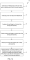
- the method 300 includes positioning 302 a wick mesh about the inflatable tube, positioning 304 the inflatable tube and the wick mesh within a receiving area of the forming shell assembly, coupling 306 a first flange to a first side of the forming shell assembly, coupling 308 a second flange to a second side of the forming shell assembly, clamping 310 the forming shell assembly with a clamp plate assembly, and applying pressure 312, via a source of pressure, to the inflatable tube through the hydraulic opening to transition the expandable tube toward an inflated configuration to press the wick mesh against an inner surface of the forming shell assembly.
- the method 300 can optionally include transitioning the inflatable tube towards a deflated configuration and removing the wick from the inflatable tube.
- the method 300 can optionally include removing the wick from the inflatable tube comprises removing the wick from the inflatable tube absent chemical intervention.
- the method 300 includes positioning the inflatable tube about a porous support tube.
- the method can optionally include positioning a first o-ring, a first portion of the porous support tube, and a first portion of the expandable tube uncaptured by the wick mesh in a first receiving area defined in the first flange and positioning a second o-ring, a second portion of the porous support tube, and a second portion of the expandable tube uncaptured by the wick mesh in a second receiving area defined in the second flange.
- Example 1 - A forming assembly configured to form a wick, the forming assembly comprising an expandable tube and a forming shell assembly.
- the expandable tube is hydraulically expandable to an expanded configuration.
- a wick mesh is configured to be wrapped about the expandable tube.
- the forming shell assembly comprises a first forming shell comprising a first recess defined therein and a second forming shell comprising a second recess defined therein. The first recess and the second recess cooperate to define an outer diameter of the formed wick.
- the expandable tube and the wick mesh are positionable between the first recess and the second recess.
- the expandable tube and the forming shell assembly are configured to deform the wick mesh and form the wick based on the expandable tube hydraulically expanding towards the expanded configuration.
- Example 2 The forming assembly of Example 1, wherein the wick is configured to separate from expandable tube based on the expandable tube transitioning toward an unexpanded configuration.
- Example 3 The forming assembly of Example 2, wherein the wick is configured to separate from expandable tube absent chemical intervention.
- Example 4 The forming assembly of any one of Examples 1-3, wherein the expandable tube comprises polyurethane.
- Example 5 The forming assembly of any one of Examples 1-4, further comprising a clamp plate assembly configured to clamp the first forming shell to the second forming shell.
- the clamp plate assembly comprises a first clamp plate configured to abut the first forming shell, a second clamp plate configured to abut the second forming shell, and a fastener configured to fasten the first clamp plate to the second clamp plate.
- Example 6 The forming assembly of any one of Examples 1-5, further comprising a support tube positionable within the expandable tube.
- the support tube comprises pores defined therein. The pores are configured to fluidically couple a source of pressure to the expandable tube.
- Example 7 The forming assembly of any one of Examples 1-6, further comprising an end flange configured to couple the first forming shell to the second forming shell.
- the end flange comprises a hydraulic opening defined therein.
- the expandable tube is configurable to hydraulically expand towards the expanded configuration based on pressure applied through the hydraulic opening by a source of pressure.
- Example 8 The forming assembly of Example 7, wherein the end flange comprises a receiving area configured to receive an o-ring and a portion of the expandable tube uncaptured by the wick mesh therein.
- Example 9 A method of forming a wick by a forming shell assembly including an inflatable tube, the method comprising positioning a wick mesh about the inflatable tube, positioning the inflatable tube and the wick mesh within a receiving area of the forming shell assembly, coupling a first end flange to a first side of the forming shell assembly, and coupling a second end flange to a second side of the forming shell assembly.
- the first end flange comprises a hydraulic opening defined therein. The hydraulic opening is in fluid communication with the expandable tube.
- the method further comprises clamping the forming shell assembly with a clamp plate assembly and applying pressure, via a source of pressure, to the inflatable tube through the hydraulic opening to transition the expandable tube toward an inflated configuration to press the wick mesh against an inner surface of the forming shell assembly.
- Example 10 The method of Example 9, wherein applying pressure to the inflatable tube comprises applying pressure to the inflatable tube such that the inflatable tube plastically deforms the wick mesh and forms the wick.
- Example 11 The method of Example 10. further comprising transitioning the inflatable tube towards a deflated configuration and removing the wick from the inflatable tube.
- Example 12 The method of Example 11, wherein removing the wick from the inflatable tube comprises removing the wick from the inflatable tube absent chemical intervention.
- Example 13 The method of any one of Examples 9-12, further comprising positioning the inflatable tube about a porous support tube. Pores defined in the porous support tube are configured to fluidically couple the source of pressure to the inflatable tube.
- Example 14 The method of Example 13, further comprising positioning a first o-ring, a first portion of the porous support tube, and a first portion of the expandable tube uncaptured by the wick mesh in a first receiving area defined in the first end flange and positioning a second o-ring, a second portion of the porous support tube, and a second portion of the expandable tube uncaptured by the wick mesh in a second receiving area defined in the second end flange.
- Example 15 - A forming assembly configured to form a wick, the forming assembly comprising a wick assembly comprising a porous support tube comprising pores defined therein and an inflatable tube configurable between a delated configuration and an inflated configuration.
- the inflatable tube is positioned about the porous support tube.
- a wick mesh is configured to be wrapped about the inflatable tube.
- the forming assembly further comprises a forming shell assembly comprises a first forming shell comprising a first recess defined therein and a second forming shell comprising a second recess defined therein.
- the wick assembly is positionable between the first recess and the second recess.
- the forming shell assembly further comprises a first end flange and a second end flange.
- the first end flange is couplable to the first forming shell and the second forming shell.
- the first end flange comprises a first receiving area configured to receive a first o-ring, a first portion of the porous support tube. and a first portion of the inflatable tube therein and a hydraulic opening configured to fluidically couple a source of pressure to the inflatable tube.
- the second end flange is couplable to the first forming shell and the second forming shell.
- the second end flange comprises a second receiving area configured to receive a second o-ring, a second portion of the porous support tube. and a second portion of the inflatable tube therein.
- Example 16 The forming assembly of Example 15, further comprising means for preventing the first forming shell and the second forming shell from separating as the inflatable tube is inflated toward the inflated configuration.
- Example 17 The forming assembly of Examples 15 or 16, wherein the inflatable tube comprises polyurethane.
- Example 18 The forming assembly of any one of Examples 15-17, wherein the first recess and the second recess are configured to define an outer diameter of the wick.
- Example 20 The forming assembly of Example 19, wherein the wick is configured to separate from inflatable tube absent chemical intervention.
- One or more components may be referred to herein as “configured to,” “configurable to,” “operable/operative to,” “adapted/adaptable.” “able to,” “conformable/conformed to,” etc. Those skilled in the art will recognize that “configured to” can generally encompass active-state components and/or inactive-state components and/or standby-state components. unless context requires otherwise.
- B, or C would include but not be limited to systems that have A alone, B alone, C alone, A and B together, A and C together, B and C together, and/or A, B, and C together, etc.). It will be further understood by those within the art that typically a disjunctive word and/or phrase presenting two or more alternative terms, whether in the description, claims, or drawings, should be understood to contemplate the possibilities of including one of the terms, either of the terms, or both terms unless context dictates otherwise. For example, the phrase "A or B" will be typically understood to include the possibilities of "A” or "B” or "A and B.”
- any reference to “one aspect.” “an aspect.” “an exemplification,” “one exemplification,” and the like means that a particular feature, structure, or characteristic described in connection with the aspect is included in at least one aspect.
- appearances of the phrases “in one aspect.” “in an aspect,” “in an exemplification,” and “in one exemplification” in various places throughout the specification are not necessarily all referring to the same aspect.
- the particular features, structures or characteristics may be combined in any suitable manner in one or more aspects.
- the term “substantially”, “about”, or “approximately” as used in the present disclosure means an acceptable error for a particular value as determined by one of ordinary skill in the art, which depends in part on how the value is measured or determined. In certain embodiments, the term “substantially”, “about”, or “approximately” means within 1, 2, 3, or 4 standard deviations. In certain embodiments, the term “substantially”, “about”, or “approximately” means within 50%, 20%, 15%, 10%, 9%, 8%, 7%, 6%, 5%, 4%, 3%, 2%, 1%, 0.5%, or 0.05% of a given value or range.
Landscapes
- Engineering & Computer Science (AREA)
- Mechanical Engineering (AREA)
- Physics & Mathematics (AREA)
- Life Sciences & Earth Sciences (AREA)
- Sustainable Development (AREA)
- Thermal Sciences (AREA)
- General Engineering & Computer Science (AREA)
- Fluid Mechanics (AREA)
- Shaping Metal By Deep-Drawing, Or The Like (AREA)
- Heat-Exchange Devices With Radiators And Conduit Assemblies (AREA)
- Casting Or Compression Moulding Of Plastics Or The Like (AREA)
- Moulds For Moulding Plastics Or The Like (AREA)
Claims (15)
- Formanordnung, die zum Formen eines Dochtes konfiguriert ist, wobei die Formanordnung (200) umfasst:ein ausdehnbares Rohr (202), das hydraulisch in eine ausgedehnte Konfiguration ausdehnbar ist, wobei ein Dochtnetz (204) um das ausdehnbare Rohr (202) gewickelt werden kann; undeine Formschalenanordnung (210), umfassend:eine erste Formschale (212), umfassend eine darin definierte erste Aussparung (213); undeine zweite Formschale (214) umfassend eine darin definierte zweite Aussparung (215), wobei die erste Aussparung (213) und die zweite Aussparung (215) zusammenwirken, um einen Außendurchmesser des Dochts zu definieren, und wobei das ausdehnbare Rohr (202) und das Dochtnetz (204) zwischen der ersten Aussparung (213) und der zweiten Aussparung (215) positionierbar sind;wobei das ausdehnbare Rohr (202) und die Formschalenanordnung (210) dazu konfiguriert sind, das Dochtnetz (204) zu verformen und den Docht basierend auf dem ausdehnbaren Rohr (202), das sich hydraulisch in Richtung der ausgedehnten Konfiguration ausdehnt, zu formen; undein Stützrohr (206), das innerhalb des ausdehnbaren Rohrs (202) positionierbar ist, wobei das Stützrohr (206) darin definierte Poren umfasst, wobei die Poren so konfiguriert sind, dass sie eine Druckquelle fluidisch mit dem ausdehnbaren Rohr (202) verbinden.
- Formanordnung nach Anspruch 1, wobei das ausdehnbare Rohr (202) dazu konfiguriert ist, sich von dem Dochtnetz (204) zu trennen, wenn das ausdehnbare Rohr (202) ohne die Notwendigkeit eines chemischen Eingriffs in eine nicht ausgedehnte Konfiguration übergeht.
- Formanordnung nach Anspruch 1, wobei das ausdehnbare Rohr (202) Polyurethan umfasst.
- Formanordnung nach Anspruch 1, die ferner eine Klemmplattenanordnung (240) umfasst, die dazu konfiguriert ist, die erste Formschale (212) an die zweite Formschale (214) zu klemmen, wobei die Klemmplattenanordnung (240) umfasst:eine erste Klemmplatte (242), die so konfiguriert ist, dass sie an der ersten Formschale (212) anliegt;eine zweite Klemmplatte (244), die so konfiguriert ist, dass sie an der zweiten Formschale (214) anliegt; undein Befestigungselement (246), das dazu konfiguriert ist, die erste Klemmplatte (242) an der zweiten Klemmplatte (244) zu befestigen.
- Formanordnung nach Anspruch 1, die ferner einen Endflansch (220) umfasst, der dazu konfiguriert ist, die erste Formschale (212) mit der zweiten Formschale (214) zu koppeln, wobei der Endflansch (220) eine darin definierte hydraulische Öffnung (232) umfasst und wobei das ausdehnbare Rohr (202) dazu konfigurierbar ist, sich basierend auf dem von einer Druckquelle durch die hydraulische Öffnung (232) aufgebrachten Druck hydraulisch in Richtung der ausgedehnten Konfiguration auszudehnen.
- Formanordnung nach Anspruch 5, wobei der Endflansch (220) einen Aufnahmebereich (228) umfasst, der dazu konfiguriert ist, einen O-Ring (234) und einen Abschnitt (208) des ausdehnbaren Rohrs aufzunehmen, der nicht von dem Dochtnetz (204) darin erfasst wird.
- Verfahren zum Formen eines Dochts durch eine Formanordnung (200) nach Anspruch 1, wobei das Verfahren umfasst:Positionieren (304) eines Dochtnetzes (204) um das ausdehnbare Rohr (202), das ein aufblasbares Rohr (202) ist;Positionieren (302) des aufblasbaren Rohrs (202) und des Dochtnetzes (204) in einem Aufnahmebereich (228) der Formschalenanordnung (210);Koppeln (306) eines ersten Endflansches (220) mit einer ersten Seite der Formschalenanordnung (210);Koppeln (308) eines zweiten Endflansches (222) mit einer zweiten Seite der Formschalenanordnung (210), wobei der erste Endflansch (220) eine darin definierte Hydrauliköffnung umfasst und wobei die Hydrauliköffnung (232) in Fluidverbindung mit dem aufblasbaren Rohr (202) steht;Festklemmen (310) der Formschalenanordnung (210) mit einer Klemmplattenanordnung (240); undAufbringen von Druck (312) über eine Druckquelle auf das aufblasbare Rohr (202) durch die hydraulische Öffnung (232), um das aufblasbare Rohr (202) in eine aufgeblasene Konfiguration zu überführen und das Dochtnetz (204) gegen eine Innenfläche der sich bildenden Schalenanordnung (210) zu drücken;und Positionieren des aufblasbaren Rohrs (202) um das poröse Trägerrohr (206).
- Verfahren nach Anspruch 7, wobei das Aufbringen von Druck auf das aufblasbare Rohr (202) das Aufbringen von Druck auf das aufblasbare Rohr (202) derart umfasst, dass das aufblasbare Rohr (202) das Dochtnetz (204) plastisch verformt und den Docht bildet.
- Verfahren nach Anspruch 8, ferner umfassend:Überführen des aufblasbaren Rohrs (202) in eine entleerte Konfiguration; undEntfernen des Dochts aus dem aufblasbaren Schlauch (202), ohne die Notwendigkeit eines chemischen Eingriffs.
- Verfahren nach Anspruch 7, ferner umfassend:Positionieren eines ersten O-Rings (234), eines ersten Abschnitts des porösen Trägerrohrs (206) und eines ersten Abschnitts (208) des aufblasbaren Rohrs (202), der nicht von dem Dochtnetz (204) erfasst wird, in einem ersten Aufnahmebereich (228), der in dem ersten Endflansch (220) definiert ist; undPositionieren eines zweiten O-Rings (234), eines zweiten Abschnitts des porösen Trägerrohrs (206) und eines zweiten Abschnitts des aufblasbaren Rohrs (202), der nicht vom Dochtnetz erfasst wird, in einem zweiten Aufnahmebereich (228), der in dem zweiten Endflansch (222) definiert ist.
- Dochtformanordnung, die zum Formen eines Dochtes konfiguriert ist, umfassendein aufblasbares Rohr (202), das zwischen einer entleerten Konfiguration und einer aufgeblasenen Konfiguration konfigurierbar ist, wobei ein Dochtnetz (204) um das aufblasbare Rohr (220) gewickelt werden kann; undeine Formschalenanordnung (210), umfassend:eine erste Formschale (212), umfassend eine darin definierte erste Aussparung (213);eine zweite Formschale (214), umfassend eine darin definierte zweiten Aussparung (215), wobei die Dochtformanordnung (201) zwischen der ersten Aussparung (213) und der zweiten Aussparung (215) positionierbar ist;einen ersten Endflansch (220), der mit der ersten Formschale (212) und der zweiten Formschale (214) koppelbar ist, wobei der erste Endflansch (220) umfasst:einen ersten Aufnahmebereich (228), der dazu konfiguriert ist, einen ersten O-Ring (234) und einen ersten Abschnitt des aufblasbaren Rohrs (202) darin aufzunehmen; undeine hydraulische Öffnung (232), die dazu konfiguriert ist, eine Druckquelle fluidisch mit dem aufblasbaren Rohr (202) zu koppeln; undeinen zweiten Endflansch (222), der mit der ersten Formschale (212) und der zweiten Formschale (214) koppelbar ist, wobei der zweite Endflansch (222) einen zweiten Aufnahmebereich (228) umfasst, der so konfiguriert ist, dass er einen zweiten O-Ring (234) und einen zweiten Abschnitt des aufblasbaren Schlauchs (202) darin aufnimmt, unddie Dochtformanordnung umfasst ein poröses Trägerrohr (206) mit darin definierten Poren;wobei das aufblasbare Rohr (202) um das poröse Trägerrohr (206) herum positioniert ist,der erste Aufnahmebereich (228) so konfiguriert ist, dass er einen ersten Abschnitt des porösen Trägerrohrs (206) aufnimmt, undder zweite Aufnahmebereich (228) so konfiguriert ist, dass er ferner einen zweiten Abschnitt des porösen Trägerrohrs (206) aufnimmt.
- Formanordnung nach Anspruch 11, die ferner Mittel umfasst, die verhindern, dass sich die erste Formschale (212) und die zweite Formschale (214) trennen, wenn das aufblasbare Rohr (202) in Richtung der aufgeblasenen Konfiguration aufgeblasen wird.
- Formanordnung nach Anspruch 11, wobei das aufblasbare Rohr (202) Polyurethan umfasst.
- Formanordnung nach Anspruch 11, wobei die erste Aussparung (213) und die zweite Aussparung (215) so konfiguriert sind, dass sie einen Außendurchmesser des Dochts definieren.
- Formanordnung nach Anspruch 11, wobei das aufblasbare Rohr (202) dazu konfiguriert ist, das Dochtnetz (204) zu verformen und den Docht basierend auf dem Übergang des aufblasbaren Rohrs (202) in die aufgeblasene Konfiguration zu formen, wie mit dem aufblasbaren Rohr (202), das dazu konfiguriert ist, sich ohne die Notwendigkeit eines chemischen Eingriffs vom Docht zu trennen.
Priority Applications (1)
| Application Number | Priority Date | Filing Date | Title |
|---|---|---|---|
| SI202130327T SI4139067T1 (sl) | 2020-04-20 | 2021-04-20 | Notranja hidrooblikovalna metoda za izdelavo stenja toplotnih cevi |
Applications Claiming Priority (2)
| Application Number | Priority Date | Filing Date | Title |
|---|---|---|---|
| US16/853,270 US11780122B2 (en) | 2020-04-20 | 2020-04-20 | Internal hydroforming method for manufacturing heat pipe wicks |
| PCT/US2021/028129 WO2021216532A1 (en) | 2020-04-20 | 2021-04-20 | Internal hydroforming method for manufacturing heat pipe wicks |
Publications (2)
| Publication Number | Publication Date |
|---|---|
| EP4139067A1 EP4139067A1 (de) | 2023-03-01 |
| EP4139067B1 true EP4139067B1 (de) | 2025-06-04 |
Family
ID=75870770
Family Applications (1)
| Application Number | Title | Priority Date | Filing Date |
|---|---|---|---|
| EP21724469.8A Active EP4139067B1 (de) | 2020-04-20 | 2021-04-20 | Innenhochdruckumformverfahren zur herstellung von wärmerohrdochten |
Country Status (12)
| Country | Link |
|---|---|
| US (2) | US11780122B2 (de) |
| EP (1) | EP4139067B1 (de) |
| JP (1) | JP7626782B2 (de) |
| KR (1) | KR20230002517A (de) |
| CA (1) | CA3176239A1 (de) |
| ES (1) | ES3037175T3 (de) |
| FI (1) | FI4139067T3 (de) |
| PL (1) | PL4139067T3 (de) |
| SI (1) | SI4139067T1 (de) |
| TW (1) | TWI795763B (de) |
| WO (1) | WO2021216532A1 (de) |
| ZA (1) | ZA202211792B (de) |
Families Citing this family (3)
| Publication number | Priority date | Publication date | Assignee | Title |
|---|---|---|---|---|
| EP4596136A3 (de) * | 2020-04-20 | 2025-10-29 | Westinghouse Electric Company Llc | Innenhochdruckumformverfahren zur herstellung von wärmerohrdochten unter verwendung eines hohlen dorns und einer hülle |
| IT202100021119A1 (it) * | 2021-08-04 | 2023-02-04 | Carbopress Spa | Procedimento di realizzazione di manufatti cavi in materiale composito |
| WO2026054868A1 (en) * | 2024-09-07 | 2026-03-12 | Westinghouse Electric Company Llc | Methods and devices for forming a wick |
Family Cites Families (36)
| Publication number | Priority date | Publication date | Assignee | Title |
|---|---|---|---|---|
| US2999780A (en) * | 1953-11-13 | 1961-09-12 | H D Boggs Company Ltd | Method of casting tubular articles |
| US3156598A (en) * | 1961-06-12 | 1964-11-10 | Smith Corp A O | Method of making a fiber reinforced resin tubular article |
| US3257690A (en) * | 1963-02-14 | 1966-06-28 | Babbitt Pipe Company Inc | Mandrel |
| US3290728A (en) * | 1964-02-10 | 1966-12-13 | Babbitt Pipe Company Inc | Plastic pipe molding apparatus |
| US3561079A (en) * | 1968-03-11 | 1971-02-09 | Robinson Clay Product Co The | Apparatus for pressing of clay pipe using an elastomeric mandrel |
| US3681843A (en) * | 1970-03-06 | 1972-08-08 | Westinghouse Electric Corp | Heat pipe wick fabrication |
| US4049762A (en) * | 1973-08-03 | 1977-09-20 | Harsco Corporation | Method of forming a pipe coupling |
| US3964902A (en) | 1974-02-27 | 1976-06-22 | The United States Of America As Represented By The United States National Aeronautics And Space Administration | Method of forming a wick for a heat pipe |
| JPS548108Y2 (de) * | 1975-08-04 | 1979-04-14 | ||
| US4186796A (en) * | 1977-05-17 | 1980-02-05 | Usui International Industry, Ltd. | Heat pipe element |
| US4186793A (en) | 1978-03-17 | 1980-02-05 | Antonov Vladimir A | Automatic line for coated metal mould casting |
| JPS5596890A (en) | 1979-01-17 | 1980-07-23 | Hitachi Cable Ltd | Method of fixing wick in heat pipe |
| NL8005711A (nl) * | 1979-10-18 | 1981-04-22 | Tungum Hydraulics Ltd | Pijpkoppeling met axiaal bewegende delen. |
| JPS58156191A (ja) * | 1982-03-10 | 1983-09-17 | Sumitomo Light Metal Ind Ltd | ウイツク型ヒ−トパイプの製造法 |
| US4876049A (en) * | 1985-11-21 | 1989-10-24 | Nippon Petrochemicals Co., Ltd. | Method for preparing molded articles of ultra-high molecular weight polyethylene |
| JPH0526241Y2 (de) * | 1986-04-28 | 1993-07-02 | ||
| US5071506A (en) * | 1987-10-09 | 1991-12-10 | Thiokol Corporation | Equipment for making composite tubes including an inflatable heated bladder and a composite mold having a negative coefficient of thermal expansion |
| SU1611678A1 (ru) | 1988-07-27 | 1990-12-07 | Азербайжданский Институт Нефти И Химии Им.М.Азизбекова | Способ изготовлени тепловой трубы |
| US5624519A (en) * | 1992-05-29 | 1997-04-29 | Trek Bicycle, Corp. | Method making a composite bicycle frame using composite lugs |
| JPH09119789A (ja) | 1995-10-24 | 1997-05-06 | Mitsubishi Materials Corp | ヒートパイプの製造方法 |
| US5684848A (en) | 1996-05-06 | 1997-11-04 | General Electric Company | Nuclear reactor heat pipe |
| US6071460A (en) * | 1997-08-15 | 2000-06-06 | Taylor Made Golf Company Inc. | Method of manufacturing a golf shaft of complex shape by internal bladder pressurization |
| KR20040031175A (ko) * | 2002-10-04 | 2004-04-13 | 주식회사 성우하이텍 | 알루미늄 합금의 온간 액압 성형 방법 및 그 장치 |
| US20040092330A1 (en) * | 2002-11-12 | 2004-05-13 | Meyer Jeffrey W. | Hybrid golf club shaft |
| JP4251900B2 (ja) * | 2003-03-28 | 2009-04-08 | 藤倉ゴム工業株式会社 | 中空frp成形品の内圧成形方法及び装置 |
| US6768781B1 (en) | 2003-03-31 | 2004-07-27 | The Boeing Company | Methods and apparatuses for removing thermal energy from a nuclear reactor |
| US20060207749A1 (en) | 2005-03-18 | 2006-09-21 | Jaffe Limited | Multi-layer wick structure of heat pipe |
| US7972129B2 (en) * | 2005-09-16 | 2011-07-05 | O'donoghue Joseph | Compound tooling system for molding applications |
| WO2009041433A1 (ja) | 2007-09-26 | 2009-04-02 | Iwaki Co., Ltd. | ポリテトラフルオロエチレン製ベローズ、その製造方法、その製造装置およびそれを用いた流体圧送機器 |
| KR101132891B1 (ko) | 2008-12-19 | 2012-04-03 | 현대하이스코 주식회사 | 관재 고압 액압성형을 이용한 다중복합강관 및 그 제조 방법 |
| DE102011102087A1 (de) | 2011-05-19 | 2012-11-22 | Formtech Gmbh | Verfahren zur Bearbeitung eines Flächenelements |
| TW201309996A (zh) | 2011-08-17 | 2013-03-01 | Chaun Choung Technology Corp | 輕量化熱管之製造方法及其成品 |
| US9433991B2 (en) | 2011-12-21 | 2016-09-06 | Edwards Lifesciences Corporation | Apparatus and method for stent shaping |
| US10643756B2 (en) | 2013-04-25 | 2020-05-05 | Triad National Security, Llc | Mobile heat pipe cooled fast reactor system |
| KR101703089B1 (ko) | 2016-02-02 | 2017-02-06 | 김성식 | 내부보호관을 갖는 금속파이프와 이의 제조방법 |
| US10751955B2 (en) * | 2017-04-10 | 2020-08-25 | The Boeing Company | Unitized composite structure manufacturing system |
-
2020
- 2020-04-20 US US16/853,270 patent/US11780122B2/en active Active
-
2021
- 2021-04-20 KR KR1020227037567A patent/KR20230002517A/ko active Pending
- 2021-04-20 TW TW110114213A patent/TWI795763B/zh active
- 2021-04-20 EP EP21724469.8A patent/EP4139067B1/de active Active
- 2021-04-20 WO PCT/US2021/028129 patent/WO2021216532A1/en not_active Ceased
- 2021-04-20 JP JP2022563478A patent/JP7626782B2/ja active Active
- 2021-04-20 FI FIEP21724469.8T patent/FI4139067T3/fi active
- 2021-04-20 CA CA3176239A patent/CA3176239A1/en active Pending
- 2021-04-20 SI SI202130327T patent/SI4139067T1/sl unknown
- 2021-04-20 ES ES21724469T patent/ES3037175T3/es active Active
- 2021-04-20 PL PL21724469.8T patent/PL4139067T3/pl unknown
-
2022
- 2022-10-28 ZA ZA2022/11792A patent/ZA202211792B/en unknown
-
2023
- 2023-07-31 US US18/362,689 patent/US12269196B2/en active Active
Also Published As
| Publication number | Publication date |
|---|---|
| TWI795763B (zh) | 2023-03-11 |
| US11780122B2 (en) | 2023-10-10 |
| JP2023523408A (ja) | 2023-06-05 |
| JP7626782B2 (ja) | 2025-02-04 |
| KR20230002517A (ko) | 2023-01-05 |
| CA3176239A1 (en) | 2021-10-28 |
| ES3037175T3 (en) | 2025-09-29 |
| EP4139067A1 (de) | 2023-03-01 |
| TW202216403A (zh) | 2022-05-01 |
| US12269196B2 (en) | 2025-04-08 |
| US20240017448A1 (en) | 2024-01-18 |
| WO2021216532A1 (en) | 2021-10-28 |
| FI4139067T3 (fi) | 2025-07-23 |
| SI4139067T1 (sl) | 2025-09-30 |
| PL4139067T3 (pl) | 2025-07-28 |
| ZA202211792B (en) | 2024-11-27 |
| US20210323201A1 (en) | 2021-10-21 |
Similar Documents
| Publication | Publication Date | Title |
|---|---|---|
| US12269196B2 (en) | Internal hydroforming method for manufacturing heat pipe wicks | |
| US20260042135A1 (en) | Internal hydroforming method for manufacturing heat pipe wicks utilizing a hollow mandrel and sheath | |
| EP3987200B1 (de) | Metalldichtring und verfahren zur herstellung einer metall-metall-dichtung | |
| US12305929B2 (en) | Advanced manufacturing heat pipe segment with integral printed wick | |
| EP4605154A1 (de) | Herstellung von wärmerohrdochten mit in-situ-roll- und hydroformvorrichtung | |
| EP4107463B1 (de) | Metalldocht-crimpverfahren für wärmerohreinbauten | |
| US11858075B1 (en) | Heat pipe wick bonding through crimping | |
| US12611740B2 (en) | Methods for attaching a wick plug to a wick | |
| WO2026054868A1 (en) | Methods and devices for forming a wick |
Legal Events
| Date | Code | Title | Description |
|---|---|---|---|
| STAA | Information on the status of an ep patent application or granted ep patent |
Free format text: STATUS: UNKNOWN |
|
| STAA | Information on the status of an ep patent application or granted ep patent |
Free format text: STATUS: THE INTERNATIONAL PUBLICATION HAS BEEN MADE |
|
| PUAI | Public reference made under article 153(3) epc to a published international application that has entered the european phase |
Free format text: ORIGINAL CODE: 0009012 |
|
| STAA | Information on the status of an ep patent application or granted ep patent |
Free format text: STATUS: REQUEST FOR EXAMINATION WAS MADE |
|
| 17P | Request for examination filed |
Effective date: 20221019 |
|
| AK | Designated contracting states |
Kind code of ref document: A1 Designated state(s): AL AT BE BG CH CY CZ DE DK EE ES FI FR GB GR HR HU IE IS IT LI LT LU LV MC MK MT NL NO PL PT RO RS SE SI SK SM TR |
|
| DAV | Request for validation of the european patent (deleted) | ||
| DAX | Request for extension of the european patent (deleted) | ||
| GRAP | Despatch of communication of intention to grant a patent |
Free format text: ORIGINAL CODE: EPIDOSNIGR1 |
|
| STAA | Information on the status of an ep patent application or granted ep patent |
Free format text: STATUS: GRANT OF PATENT IS INTENDED |
|
| INTG | Intention to grant announced |
Effective date: 20250103 |
|
| GRAS | Grant fee paid |
Free format text: ORIGINAL CODE: EPIDOSNIGR3 |
|
| GRAA | (expected) grant |
Free format text: ORIGINAL CODE: 0009210 |
|
| STAA | Information on the status of an ep patent application or granted ep patent |
Free format text: STATUS: THE PATENT HAS BEEN GRANTED |
|
| AK | Designated contracting states |
Kind code of ref document: B1 Designated state(s): AL AT BE BG CH CY CZ DE DK EE ES FI FR GB GR HR HU IE IS IT LI LT LU LV MC MK MT NL NO PL PT RO RS SE SI SK SM TR |
|
| REG | Reference to a national code |
Ref country code: GB Ref legal event code: FG4D |
|
| REG | Reference to a national code |
Ref country code: CH Ref legal event code: EP |
|
| REG | Reference to a national code |
Ref country code: DE Ref legal event code: R096 Ref document number: 602021031777 Country of ref document: DE |
|
| REG | Reference to a national code |
Ref country code: SE Ref legal event code: TRGR |
|
| REG | Reference to a national code |
Ref country code: IE Ref legal event code: FG4D |
|
| REG | Reference to a national code |
Ref country code: NL Ref legal event code: FP |
|
| REG | Reference to a national code |
Ref country code: FI Ref legal event code: FGE |
|
| REG | Reference to a national code |
Ref country code: ES Ref legal event code: FG2A Ref document number: 3037175 Country of ref document: ES Kind code of ref document: T3 Effective date: 20250929 |
|
| REG | Reference to a national code |
Ref country code: LT Ref legal event code: MG9D |
|
| PG25 | Lapsed in a contracting state [announced via postgrant information from national office to epo] |
Ref country code: GR Free format text: LAPSE BECAUSE OF FAILURE TO SUBMIT A TRANSLATION OF THE DESCRIPTION OR TO PAY THE FEE WITHIN THE PRESCRIBED TIME-LIMIT Effective date: 20250905 Ref country code: NO Free format text: LAPSE BECAUSE OF FAILURE TO SUBMIT A TRANSLATION OF THE DESCRIPTION OR TO PAY THE FEE WITHIN THE PRESCRIBED TIME-LIMIT Effective date: 20250904 |
|
| PG25 | Lapsed in a contracting state [announced via postgrant information from national office to epo] |
Ref country code: BG Free format text: LAPSE BECAUSE OF FAILURE TO SUBMIT A TRANSLATION OF THE DESCRIPTION OR TO PAY THE FEE WITHIN THE PRESCRIBED TIME-LIMIT Effective date: 20250604 |
|
| PG25 | Lapsed in a contracting state [announced via postgrant information from national office to epo] |
Ref country code: HR Free format text: LAPSE BECAUSE OF FAILURE TO SUBMIT A TRANSLATION OF THE DESCRIPTION OR TO PAY THE FEE WITHIN THE PRESCRIBED TIME-LIMIT Effective date: 20250604 |
|
| PG25 | Lapsed in a contracting state [announced via postgrant information from national office to epo] |
Ref country code: RS Free format text: LAPSE BECAUSE OF FAILURE TO SUBMIT A TRANSLATION OF THE DESCRIPTION OR TO PAY THE FEE WITHIN THE PRESCRIBED TIME-LIMIT Effective date: 20250904 |
|
| PG25 | Lapsed in a contracting state [announced via postgrant information from national office to epo] |
Ref country code: LV Free format text: LAPSE BECAUSE OF FAILURE TO SUBMIT A TRANSLATION OF THE DESCRIPTION OR TO PAY THE FEE WITHIN THE PRESCRIBED TIME-LIMIT Effective date: 20250604 |
|
| PG25 | Lapsed in a contracting state [announced via postgrant information from national office to epo] |
Ref country code: PT Free format text: LAPSE BECAUSE OF FAILURE TO SUBMIT A TRANSLATION OF THE DESCRIPTION OR TO PAY THE FEE WITHIN THE PRESCRIBED TIME-LIMIT Effective date: 20251006 |
|
| REG | Reference to a national code |
Ref country code: AT Ref legal event code: MK05 Ref document number: 1799897 Country of ref document: AT Kind code of ref document: T Effective date: 20250604 |
|
| PG25 | Lapsed in a contracting state [announced via postgrant information from national office to epo] |
Ref country code: IS Free format text: LAPSE BECAUSE OF FAILURE TO SUBMIT A TRANSLATION OF THE DESCRIPTION OR TO PAY THE FEE WITHIN THE PRESCRIBED TIME-LIMIT Effective date: 20251004 |
|
| PG25 | Lapsed in a contracting state [announced via postgrant information from national office to epo] |
Ref country code: AT Free format text: LAPSE BECAUSE OF FAILURE TO SUBMIT A TRANSLATION OF THE DESCRIPTION OR TO PAY THE FEE WITHIN THE PRESCRIBED TIME-LIMIT Effective date: 20250604 Ref country code: SM Free format text: LAPSE BECAUSE OF FAILURE TO SUBMIT A TRANSLATION OF THE DESCRIPTION OR TO PAY THE FEE WITHIN THE PRESCRIBED TIME-LIMIT Effective date: 20250604 |
|
| PG25 | Lapsed in a contracting state [announced via postgrant information from national office to epo] |
Ref country code: CZ Free format text: LAPSE BECAUSE OF FAILURE TO SUBMIT A TRANSLATION OF THE DESCRIPTION OR TO PAY THE FEE WITHIN THE PRESCRIBED TIME-LIMIT Effective date: 20250604 |
|
| PG25 | Lapsed in a contracting state [announced via postgrant information from national office to epo] |
Ref country code: EE Free format text: LAPSE BECAUSE OF FAILURE TO SUBMIT A TRANSLATION OF THE DESCRIPTION OR TO PAY THE FEE WITHIN THE PRESCRIBED TIME-LIMIT Effective date: 20250604 |
|
| PG25 | Lapsed in a contracting state [announced via postgrant information from national office to epo] |
Ref country code: SK Free format text: LAPSE BECAUSE OF FAILURE TO SUBMIT A TRANSLATION OF THE DESCRIPTION OR TO PAY THE FEE WITHIN THE PRESCRIBED TIME-LIMIT Effective date: 20250604 |
|
| REG | Reference to a national code |
Ref country code: DE Ref legal event code: R097 Ref document number: 602021031777 Country of ref document: DE |
|
| PLBE | No opposition filed within time limit |
Free format text: ORIGINAL CODE: 0009261 |
|
| STAA | Information on the status of an ep patent application or granted ep patent |
Free format text: STATUS: NO OPPOSITION FILED WITHIN TIME LIMIT |
|
| PG25 | Lapsed in a contracting state [announced via postgrant information from national office to epo] |
Ref country code: DK Free format text: LAPSE BECAUSE OF FAILURE TO SUBMIT A TRANSLATION OF THE DESCRIPTION OR TO PAY THE FEE WITHIN THE PRESCRIBED TIME-LIMIT Effective date: 20250604 |
|
| PGFP | Annual fee paid to national office [announced via postgrant information from national office to epo] |
Ref country code: RO Payment date: 20260331 Year of fee payment: 6 Ref country code: FI Payment date: 20260312 Year of fee payment: 6 |
|
| PGFP | Annual fee paid to national office [announced via postgrant information from national office to epo] |
Ref country code: NL Payment date: 20260313 Year of fee payment: 6 |
|
| REG | Reference to a national code |
Ref country code: CH Ref legal event code: L10 Free format text: ST27 STATUS EVENT CODE: U-0-0-L10-L00 (AS PROVIDED BY THE NATIONAL OFFICE) Effective date: 20260416 |
|
| PGFP | Annual fee paid to national office [announced via postgrant information from national office to epo] |
Ref country code: PL Payment date: 20260304 Year of fee payment: 6 |