EP4139532B1 - Poutre en acier - Google Patents
Poutre en acier Download PDFInfo
- Publication number
- EP4139532B1 EP4139532B1 EP21720552.5A EP21720552A EP4139532B1 EP 4139532 B1 EP4139532 B1 EP 4139532B1 EP 21720552 A EP21720552 A EP 21720552A EP 4139532 B1 EP4139532 B1 EP 4139532B1
- Authority
- EP
- European Patent Office
- Prior art keywords
- steel beam
- fill space
- end plate
- slot
- plate
- Prior art date
- Legal status (The legal status is an assumption and is not a legal conclusion. Google has not performed a legal analysis and makes no representation as to the accuracy of the status listed.)
- Active
Links
Images




Classifications
-
- E—FIXED CONSTRUCTIONS
- E04—BUILDING
- E04B—GENERAL BUILDING CONSTRUCTIONS; WALLS, e.g. PARTITIONS; ROOFS; FLOORS; CEILINGS; INSULATION OR OTHER PROTECTION OF BUILDINGS
- E04B1/00—Constructions in general; Structures which are not restricted either to walls, e.g. partitions, or floors or ceilings or roofs
- E04B1/18—Structures comprising elongated load-supporting parts, e.g. columns, girders, skeletons
- E04B1/24—Structures comprising elongated load-supporting parts, e.g. columns, girders, skeletons the supporting parts consisting of metal
- E04B1/2403—Connection details of the elongated load-supporting parts
-
- E—FIXED CONSTRUCTIONS
- E04—BUILDING
- E04C—STRUCTURAL ELEMENTS; BUILDING MATERIALS
- E04C3/00—Structural elongated elements designed for load-supporting
- E04C3/02—Joists; Girders, trusses, or trusslike structures, e.g. prefabricated; Lintels; Transoms; Braces
- E04C3/29—Joists; Girders, trusses, or trusslike structures, e.g. prefabricated; Lintels; Transoms; Braces built-up from parts of different material, i.e. composite structures
- E04C3/293—Joists; Girders, trusses, or trusslike structures, e.g. prefabricated; Lintels; Transoms; Braces built-up from parts of different material, i.e. composite structures the materials being steel and concrete
-
- E—FIXED CONSTRUCTIONS
- E04—BUILDING
- E04B—GENERAL BUILDING CONSTRUCTIONS; WALLS, e.g. PARTITIONS; ROOFS; FLOORS; CEILINGS; INSULATION OR OTHER PROTECTION OF BUILDINGS
- E04B5/00—Floors; Floor construction with regard to insulation; Connections specially adapted therefor
- E04B5/16—Load-carrying floor structures wholly or partly cast or similarly formed in situ
- E04B5/17—Floor structures partly formed in situ
- E04B5/23—Floor structures partly formed in situ with stiffening ribs or other beam-like formations wholly or partly prefabricated
- E04B5/29—Floor structures partly formed in situ with stiffening ribs or other beam-like formations wholly or partly prefabricated the prefabricated parts of the beams consisting wholly of metal
-
- E—FIXED CONSTRUCTIONS
- E04—BUILDING
- E04C—STRUCTURAL ELEMENTS; BUILDING MATERIALS
- E04C3/00—Structural elongated elements designed for load-supporting
- E04C3/02—Joists; Girders, trusses, or trusslike structures, e.g. prefabricated; Lintels; Transoms; Braces
- E04C3/29—Joists; Girders, trusses, or trusslike structures, e.g. prefabricated; Lintels; Transoms; Braces built-up from parts of different material, i.e. composite structures
- E04C3/291—Joists; Girders, trusses, or trusslike structures, e.g. prefabricated; Lintels; Transoms; Braces built-up from parts of different material, i.e. composite structures with apertured web
-
- E—FIXED CONSTRUCTIONS
- E04—BUILDING
- E04B—GENERAL BUILDING CONSTRUCTIONS; WALLS, e.g. PARTITIONS; ROOFS; FLOORS; CEILINGS; INSULATION OR OTHER PROTECTION OF BUILDINGS
- E04B1/00—Constructions in general; Structures which are not restricted either to walls, e.g. partitions, or floors or ceilings or roofs
- E04B1/18—Structures comprising elongated load-supporting parts, e.g. columns, girders, skeletons
- E04B1/24—Structures comprising elongated load-supporting parts, e.g. columns, girders, skeletons the supporting parts consisting of metal
- E04B1/2403—Connection details of the elongated load-supporting parts
- E04B2001/2409—Hooks, dovetails or other interlocking connections
-
- E—FIXED CONSTRUCTIONS
- E04—BUILDING
- E04B—GENERAL BUILDING CONSTRUCTIONS; WALLS, e.g. PARTITIONS; ROOFS; FLOORS; CEILINGS; INSULATION OR OTHER PROTECTION OF BUILDINGS
- E04B1/00—Constructions in general; Structures which are not restricted either to walls, e.g. partitions, or floors or ceilings or roofs
- E04B1/18—Structures comprising elongated load-supporting parts, e.g. columns, girders, skeletons
- E04B1/24—Structures comprising elongated load-supporting parts, e.g. columns, girders, skeletons the supporting parts consisting of metal
- E04B1/2403—Connection details of the elongated load-supporting parts
- E04B2001/2409—Hooks, dovetails or other interlocking connections
- E04B2001/2412—Keyhole connections
-
- E—FIXED CONSTRUCTIONS
- E04—BUILDING
- E04B—GENERAL BUILDING CONSTRUCTIONS; WALLS, e.g. PARTITIONS; ROOFS; FLOORS; CEILINGS; INSULATION OR OTHER PROTECTION OF BUILDINGS
- E04B1/00—Constructions in general; Structures which are not restricted either to walls, e.g. partitions, or floors or ceilings or roofs
- E04B1/18—Structures comprising elongated load-supporting parts, e.g. columns, girders, skeletons
- E04B1/24—Structures comprising elongated load-supporting parts, e.g. columns, girders, skeletons the supporting parts consisting of metal
- E04B1/2403—Connection details of the elongated load-supporting parts
- E04B2001/2421—Socket type connectors
-
- E—FIXED CONSTRUCTIONS
- E04—BUILDING
- E04B—GENERAL BUILDING CONSTRUCTIONS; WALLS, e.g. PARTITIONS; ROOFS; FLOORS; CEILINGS; INSULATION OR OTHER PROTECTION OF BUILDINGS
- E04B1/00—Constructions in general; Structures which are not restricted either to walls, e.g. partitions, or floors or ceilings or roofs
- E04B1/18—Structures comprising elongated load-supporting parts, e.g. columns, girders, skeletons
- E04B1/24—Structures comprising elongated load-supporting parts, e.g. columns, girders, skeletons the supporting parts consisting of metal
- E04B1/2403—Connection details of the elongated load-supporting parts
- E04B2001/2451—Connections between closed section profiles
Definitions
- the invention relates to a steel beam as defined in the preamble of independent claim 1.
- Steel beams to be filled with concrete to form steel-concrete-composite beams are normally on installation first supported on consoles arranged at a building component such as a column so that the console projects into a space of the steel beam via a console supporting slot provided at the end of the steel beam that is supported at the console and thereafter the space of the steel beam is filled i.e. casted with concrete so that the steel beam together with concrete will form a steel-concrete-composite beam.
- This casting will form a fire protection for the parts of the console in the space inside the steel beam and additionally protect parts such as bolts of the console inside the space of the steel beam from untightening.
- casted concrete will make the parts of the console inside the space of the steel beam inaccessible and this makes it impossible to dismount the steel-concrete-composite beam from the console without damaging the steel-concrete-composite beam.
- Document KR 101.779.449 B1 discloses a steel beam according to the preamble of claim 1.
- the object is to provide a steel beam that can be used to provide a steel-concrete-composite beam that provides for required fire protection of the parts of the console inside the steel beam and that is dismountable from a console of a building so that the steel-concrete-composite beam can be used as a building component at another location in the building or as a building component in another building.
- the steel beam of the invention is characterized by the definitions of independent claim 1. Preferred embodiments of the steel beam are defined in the dependent claims.
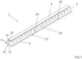
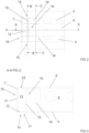
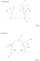
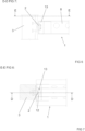
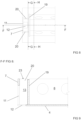
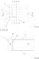
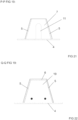
- the figures show some embodiments of the steel beam 1 and additionally supporting of some embodiments of the steel beam 1 on a console 2 provided at a column 3.
- the console 2 can alternatively be provided at another type of structure in a building that at a column 3.
- the structure in the building can for example be a steel structure, a precast or a cast-in-situ concrete structure, or a steel-concrete-composite structure.
- the steel beam 1 comprises a base plate 4, two web plates 5 extending from the base plate 4, possible a top plate 6 connecting the two web plates 5, and an end plate 7 of each end of the steel beam 1. That the steel beam 1 comprises possible a top plate 6 means in this connection that the steel beam 1 can be a steel beam 1 comprising a top plate 6 as is the case in the steel beams 1 illustrated in the figures or alternatively that the steel beam 1 can be a steel beam 1 without a top plate so that the steel beam has an open top between the web plates 5.
- At least one of the ends of the steel beam 1 comprising a console supporting slot 10 extending from said at least one end of the steel beam 1, wherein the console supporting slot 10 forms a first slot 11 in the end plate 7 of the steel beam 1 and a second slot 12 in the base plate 4 of the steel beam 1.
- the steel beam 1 comprising a fill space 13 at at least one of the ends of the steel beam 1.
- the fill space 13 being limited by a fill space housing 14 configured to separate the fill space 13 from the space 8 of the steel beam 1.
- the console supporting slot 10 is provided at least partly in the fill space 13 so that the console supporting slot 10 is separated from the space 8 of the steel beam 1 by the fill space housing 14.
- the fill space housing 14 has in addition to the supporting slot and possible air outlet openings leading out of the fill space a fill opening 23 leading into the fill space 13.
- Provision of such fill space 13 that by means of the fill space housing 14 is separated from the space 8 of the steel beam 1 so that the console supporting slot 10 of the steel beam 1 is separated from the space 8 of the steel beam 1 by means of the fill space housing 14 makes it possible to fill the fill space 13 of the steel beam 1 around the console supporting slot 10 with a fill material that provides for required fire protection of the parts of the console with are inside the fill space 13 and that is easier to remove than the hardening material such as concrete 9 the space 8 of the steel beam 1 is filled with.
- This makes it possible to remove the steel beam 1 from a console 2 without damaging the steel beam 1 in such manner that the steel beam 1 can be reused in another location in the same building or be reused in another building.
- Lime mortar can for example be used as said fill material.
- the fill space housing 14 comprises preferably, but not necessarily, at least two opposite side wall structures 15, at least two opposite end wall structures 16, and a bottom structure 17.
- the fill space housing 14 comprises at least two opposite side wall structures 15, at least two opposite end wall structures 16, and a bottom structure 17, the bottom structure 17 of the fill space housing 14 is preferably, but not necessarily, formed by the base plate 4 of the steel beam 1.
- the fill space housing 14 comprises at least two opposite side wall structures 15, at least two opposite end wall structures 16, and a bottom structure 17, one of the opposite end wall structures 16 of the fill space housing 14 is preferably, but not necessarily, formed by the end plate 7 of the steel beam 1 comprising the first slot 11.
- the fill space housing 14 comprises two opposite side wall structures 15, two opposite end wall structures 16, and a bottom structure 17.
- the bottom structure 17 of the fill space housing 14 is formed by the base plate 4 of the steel beam 1.
- one of the opposite end wall structures 16 of the fill space housing 14 is formed by the end plate 7 of the steel beam 1 comprising the first slot 11.
- the opposite side wall structures 15 of the fill space housing 14 are formed by two additional web plates 18, each additional web plate 18 extending between one of the web plates 5.
- the additional web plates 18 provides also for additional strength of the steel beam 1 at the fill space housing 14.
- the other of the opposite end wall structures 16 of the fill space housing 14 is formed by an additional end plate 19 that is provided separated from the end plate 7 of the steel beam 1 provided with the first slot 11 so that the additional end plate 19 extend between the top plate 6 of the steel beam 1, the base plate 4 of the steel beam 1, and the web plates 5 of the steel beam 1.
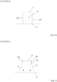
- Figures 6 and 7 shows supporting of the steel beam 1 according to the first embodiment on a console 2 provided at a column 3.
- the console 2 extends into the fill space 13 that is by means of the fill space housing 14 separated from the space 8 of the steel beam 1.
- Provision of the fill space housing 14 allows to fill the fill space 13 and the space 8 with different materials for example so that the fill space 13 is filled with a material that is easy to remove such as lime mortar, while the space 8 is filled with concrete.
- the material in the fill space 13 will provide for fire protection for a part of the steel beam 1 and the parts of console 2 inside the fill space and the material in the space 8 will provide for fire protection for another parts of the steel beam 1.
- the fill space housing 14 comprises two opposite side wall structures 15, two opposite end wall structures 16, and a bottom structure 17.
- the bottom structure 17 of the fill space housing 14 is formed by the base plate 4 of the steel beam 1.
- one of the opposite end wall structures 16 of the fill space housing 14 is formed by the end plate 7 of the steel beam 1 comprising the first slot 11.
- the other of the opposite end wall structures 16 of the fill space housing 14 is formed by an additional end plate 19 that is provided separated from the end plate 7 of the steel beam 1 comprising the first slot 11 so that the additional end plate 19 extend between the top plate 6 of the steel beam 1, the base plate 4 of the steel beam 1, and the web plates 5 of the steel beam 1.
- the opposite side wall structures 15 of the fill space housing 14 are formed by opposite side plates 20 extending between base plate 4 of the steel beam 1, the additional end plate 19, and the end plate 7 of the steel beam 1 that is provided with the first slot 11.
- the web plates 5 of the steel beam 1 are not directly connected to the end plate 7 of the steel beam 1 comprising the first slot 11, i.e. the web plates 5 of the steel beam 1 do not extend to the end plate 7 of the steel beam 1 comprising the first slot 11.
- Figures 12 and 13 shows supporting of the steel beam 1 according to the second embodiment on a console 2 provided at a column 3.
- the console 2 extends into the fill space 13 that is by means of the fill space housing 14 separated from the space 8 of the steel beam 1.
- the fill space housing 14 comprises two opposite side wall structures 15, two opposite end wall structures 16, and a bottom structure 17.
- the bottom structure 17 of the fill space housing 14 is formed by the base plate 4 of the steel beam 1.
- one of the opposite end wall structures 16 of the fill space housing 14 is formed by the end plate 7 of the steel beam 1 comprising the first slot 11.
- the opposite side wall structures 15 of the fill space housing 14 being formed by two opposite side plates 20 each extending between base plate 4 of the steel beam 1, the additional end plate 19, and the end plate 7 of the steel beam 1 that is provided with the first slot 11.
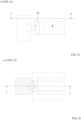
- FIGs 17 and 18 shows supporting of the steel beam 1 according to the third embodiment on a console 2 provided at a column 3.
- the console 2 extends into the fill space 13 that is by means of the fill space housing 14 separated from the space 8 of the steel beam 1.
- the fill space housing 14 comprises two opposite side wall structures 15, two opposite end wall structures 16, and a bottom structure 17.
- the bottom structure 17 of the fill space housing 14 is formed by the base plate 4 of the steel beam 1.
- one of the opposite end wall structures 16 of the fill space housing 14 is formed by the end plate 7 of the steel beam 1 comprising the first slot 11.
- the opposite side wall structures 15 of the fill space housing 14 are formed by the web plates 5 of the steel beam 1.
- the web plates 5 of the steel beam 1 extend to the end plate 7 of the steel beam 1 comprising the first slot 11 and the web plates 5 of the steel beam 1 are connected to the end plate 7 of the steel beam 1 comprising the first slot 11.
- the other of the opposite end wall structures 16 of the fill space housing 14 are formed by an additional end plate 19 that is provided separated from the end plate 7 of the steel beam 1 comprising the first slot 11 to extend between the top plate 6 of the steel beam 1, the base plate 4 of the steel beam 1, and the web plates 5 of the steel beam 1.
- the additional end plate 19 can be at least partly curved.
- the opposite side wall structures of the fill space housing 14 is formed by opposite side plates 20 as presented, the opposite side plates 20 can be at least partly curved
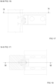
- the additional end plate 19 can be at least partly curved, and the opposite side plates 20 can be at least partly curved, as in the fifth embodiment of the steel beam illustrated in figures 25 and 26 .
- the fill space housing 14 is at least partly formed by using tube that is cut for example in half or in another way in the lengthwise or longitudinal direction of the tube to provide said additional end plate 19 and said opposite side plates 20 of the fill space housing 14.
- FIGs 23 and 24 shows supporting of the steel beam 1 according to the fourth embodiment on a console 2 provided at a column 3.
- the console 2 extends into the fill space 13 that is by means of the fill space housing 14 separated from the space 8 of the steel beam 1.
- the two web plates 5 of the steel beam 1 can be inclined in relation to the base plate 4, and by the two web plates 5 of the steel beam 1 being provided with apertures leading into the space 8 of the steel beam 1 for allowing concrete to enter the space 8 of the steel beam 1. It is also possible that one of the two web plates 5 of the steel beam 1 extending perpendicularly in relation to the base plate 4 and being essentially free of apertures, and that the other of the two web plates 5 of the steel beam 1 being inclined in relation to the base plate 4 and being provided with apertures. Other configurations of the web plates 5 of the steel beam 1 are also possible.
- At least one of the two web plates 5 of the steel beam 1 is preferably, but not necessarily, fastened to the base plate 4 of the steel beam 1 at a distance from an elongated edge 21 of the base plate 4 of the steel beam 1 so that a support flange 22 for at least one building element such a for at least one hollow core slab is formed at the base plate 4 of the steel beam 1 between the elongated edge 21 of the base plate 4 of the steel beam 1 and said at least one of the two web plates 5 of the steel beam 1.
- the possible top plate 6 of the steel beam 1 forms preferably, but not necessarily, in some variants of the steel beam 1, part of the fill space housing 14.
- the fill opening 23 of the fill space housing 14 is preferably, but not necessarily, provided at least partly between the top plate 6 of the steel beam 1 and the end plate 7 of the steel beam 1.
- the fill opening 23 of the fill space housing 14 can alternatively preferably, but not necessarily, be provided at least partly in the top plate 6 of the steel beam 1.
Landscapes
- Engineering & Computer Science (AREA)
- Architecture (AREA)
- Civil Engineering (AREA)
- Structural Engineering (AREA)
- Chemical & Material Sciences (AREA)
- Composite Materials (AREA)
- Physics & Mathematics (AREA)
- Electromagnetism (AREA)
- Joining Of Building Structures In Genera (AREA)
- Rod-Shaped Construction Members (AREA)
Claims (18)
- Poutre d'acier (1) comprenant :une plaque de base (4), deux plaques d'âme (5) émanant de la plaque de base (4) et une plaque terminale (7) de chaque extrémité de la poutre d'acier (1),dans laquelle la plaque de base (4), les deux plaques d'âme (5), les premières plaques terminales (7) délimitent un espace (8) configuré pour être rempli au moins partiellement d'un matériau durcissant (9) tel que le béton, etdans laquelle au moins l'une des extrémités de la poutre d'acier (1) comprend une fente de logement de console (10) émanant de ladite au moins une extrémité de la poutre d'acier (1), ladite fente de logement de console (10) formant une première fente (11) dans la plaque terminale (7) de la poutre d'acier (1) et une deuxième fente (12) dans la plaque de base (4) de la poutre d'acier (4),dans laquelle la poutre d'acier (1) comprend un espace de remplissage (13) à au moins l'une des extrémités de la poutre d'acier (1),dans laquelle l'espace de remplissage (13) est délimitée par une boîte d'espace de remplissage (14) configurée pour séparer l'espace de remplissage (13) de l'espace (8) de la poutre d'acier (1),dans laquelle la boîte d'espace de remplissage (14) comporte, en sus de la fente de logement de console (10) et de possibles orifices de sortie d'air conduisant à l'extérieur de l'espace de remplissage (13), un orifice de remplissage (23) menant à l'intérieur de l'espace de remplissage (13),caractérisée en ceque la fente de logement de console (10) est prévue au moins partiellement dans l'espace de remplissage de telle façon que la fente de logement de console est séparée de l'espace de la poutre d'acier par la boîte d'espace de remplissage.
- Poutre d'acier (1) selon la revendication 1, caractérisée en ce
que la boîte d'espace de remplissage (14) comprend au moins deux structures de paroi latérales opposées (15), au moins deux structures de paroi terminales opposées (16) et une structure de fond (17). - Poutre d'acier (1) selon la revendication 2, caractérisée en ce
que la structure de fond (17) de la boîte d'espace de remplissage (14) est formée par la plaque de base (4) de la poutre d'acier (1). - Poutre d'acier (1) selon la revendication 2 ou 3, caractérisée en ce
que l'une des structures de paroi terminales opposées (16) de la boîte d'espace de remplissage (14) est formée par la plaque terminale (7) de la poutre d'acier (1) comprenant la première fente (11). - Poutre d'acier (1) selon la revendication 4, caractérisée en ceque les structures de paroi latérales opposées (15) de la boîte d'espace de remplissage (14) sont formées par des plaques d'âme supplémentaires (18),que chaque plaque d'âme supplémentaire (18) s'étend entre l'une des plaques d'âme (5) de la poutre d'acier (1) et la plaque terminale (7) de la poutre d'acier (1) qui est prévue de la première fente (11),que l'autre des structures de paroi terminales opposées (16) de la boîte d'espace de remplissage (14) est formée par une plaque terminale supplémentaire (19) qui est prévue de manière séparée de la plaque terminale (7) de la poutre d'acier (1) comprenant la première fente (11), etque la plaque terminale supplémentaire (19) s'étend entre la plaque de base (4) de la poutre d'acier (1) et les plaques d'âme (5) de la poutre d'acier (1).
- Poutre d'acier (1) selon la revendication 4, caractérisée en ceque les structures de paroi latérales opposées (15) de la boîte d'espace de remplissage (14) sont formées par les plaques d'âme (5) de la poutre d'acier (1),que les plaques d'âme (5) de la poutre d'acier (1) sont reliées à la plaque terminale (7) de la poutre d'acier (1) comprenant la première fente (11),que l'autre des structures de paroi terminales opposées (16) de la boîte d'espace de remplissage (14) est formée par une plaque terminale supplémentaire (19) qui est prévue de manière séparée de la plaque terminale (7) de la poutre d'acier (1) comprenant la première fente (11), etque la plaque terminale supplémentaire (19) s'étend entre la plaque de base (4) de la poutre d'acier (1) et les plaques d'âme (5) de la poutre d'acier (1).
- Poutre d'acier (1) selon la revendication 4, caractérisée en ceque l'autre des structures de paroi terminales opposées (16) de la boîte d'espace de remplissage (14) est formée par une plaque terminale supplémentaire (19) qui est prévue de manière séparée de la plaque terminale (7) de la poutre d'acier (1) comprenant la première fente (11),que la plaque terminale supplémentaire (19) s'étend entre la plaque de base (4) de la poutre d'acier (1) et les plaques d'âme (5) de la poutre d'acier (1), etque les structures de paroi latérales opposées (15) de la boîte d'espace de remplissage (14) sont formées par des plaques latérales opposées (20) s'étendant entre la plaque de base (4) de la poutre d'acier (1), la plaque terminale supplémentaire (19) et la plaque terminale (7) de la poutre d'acier (1) qui est prévue de la première fente (11).
- Poutre d'acier (1) selon la revendication 4, caractérisée en ceque les plaques d'âme (5) de la poutre d'acier (1) sont reliées à la plaque terminale (7) de la poutre d'acier (1) comprenant la première fente (11),que l'autre des structures de paroi terminales opposées (16) de la boîte d'espace de remplissage (14) est formée par une plaque terminale supplémentaire (19) qui est prévue de manière séparée de la plaque terminale (7) de la poutre d'acier (1) comprenant la première fente (11), etque les structures de paroi latérales opposées (15) de la boîte d'espace de remplissage (14) sont formées par des plaques latérales opposées (20) s'étendant entre la plaque de base (4) de la poutre d'acier (1), la plaque terminale supplémentaire (19) et la plaque terminale (7) de la poutre d'acier (1) qui est prévue de la première fente (11).
- Poutre d'acier selon l'une des revendications 5 à 8, caractérisée en ce
que la plaque terminale supplémentaire (19) est au moins partiellement courbée. - Poutre d'acier selon la revendication 7 ou 8, caractérisée en ce
que les plaques latérales opposées (20) sont au moins partiellement courbées. - Poutre d'acier selon la revendication 7 ou 8, caractérisée en ceque la plaque terminale supplémentaire (19) est au moins partiellement courbée, etque les plaques latérales opposées (20) sont au moins partiellement courbées.
- Poutre d'acier (1) selon l'une des revendications 1 à 11, caractérisée en ceque les deux plaques d'âme (5) de la poutre d'acier (1) sont inclinées par rapport à la plaque de base (4), etque les deux plaques d'âme (5) de la poutre d'acier (1) sont pourvues d'ouvertures.
- Poutre d'acier (1) selon l'une des revendications 1 à 11, caractérisée en ceque l'une des deux plaques d'âme (5) de la poutre d'acier (1) s'étend perpendiculairement à la plaque de base (4) et est dépourvue d'ouvertures, etque l'autre des deux plaques d'âme (5) de la poutre d'acier (1) est inclinée par rapport à la plaque de base (4) et est pourvue d'ouvertures.
- Poutre d'acier (1) selon l'une des revendications 1 à 13, caractérisée en ce
qu'au moins l'une des deux plaques d'âme (5) de la poutre d'acier (1) est fixée à la plaque de base (4) de la poutre d'acier (1) à une distance par rapport à un bord allongé (21) de la plaque de base (4) de la poutre d'acier (1) de telle façon qu'une bride d'appui (22) est formée à la plaque de base (4) de la poutre d'acier (1) entre le bord allongé (21) de la plaque de base (4) de la poutre d'acier (1) et ladite au moins l'une des deux plaques d'âme (5) de la poutre d'acier (1). - Poutre d'acier (1) selon l'une des revendications 1 à 14, caractérisée en cequ'une plaque supérieure (19) relie les deux plaques d'âme (5), etque la plaque supérieure (6) délimite au moins partiellement l'espace (8) de la poutre d'acier (1).
- Poutre d'acier (1) selon la revendication 15, caractérisée en ce
que la plaque supérieure (6) de la poutre d'acier (1) forme une partie de la boîte d'espace de remplissage (14). - Poutre d'acier (1) selon la revendication 16, caractérisée en ce
que l'orifice de remplissage (23) de la boîte d'espace de remplissage (14) est prévu au moins partiellement entre la plaque supérieure (6) de la poutre d'acier (1) et la plaque terminale (7) de la poutre d'acier (1). - Poutre d'acier (1) selon l'une des revendications 15 à 17, caractérisée en ce
que l'orifice de remplissage (23) de la boîte d'espace de remplissage (14) est prévu au moins partiellement dans la plaque supérieure (6) de la poutre d'acier (1).
Applications Claiming Priority (2)
| Application Number | Priority Date | Filing Date | Title |
|---|---|---|---|
| FI20205414 | 2020-04-24 | ||
| PCT/FI2021/050267 WO2021214381A1 (fr) | 2020-04-24 | 2021-04-14 | Poutre en acier |
Publications (3)
| Publication Number | Publication Date |
|---|---|
| EP4139532A1 EP4139532A1 (fr) | 2023-03-01 |
| EP4139532B1 true EP4139532B1 (fr) | 2024-03-06 |
| EP4139532C0 EP4139532C0 (fr) | 2024-03-06 |
Family
ID=75625607
Family Applications (1)
| Application Number | Title | Priority Date | Filing Date |
|---|---|---|---|
| EP21720552.5A Active EP4139532B1 (fr) | 2020-04-24 | 2021-04-14 | Poutre en acier |
Country Status (4)
| Country | Link |
|---|---|
| US (1) | US12241247B2 (fr) |
| EP (1) | EP4139532B1 (fr) |
| CA (1) | CA3177551A1 (fr) |
| WO (1) | WO2021214381A1 (fr) |
Families Citing this family (1)
| Publication number | Priority date | Publication date | Assignee | Title |
|---|---|---|---|---|
| EP4636187A1 (fr) * | 2024-04-15 | 2025-10-22 | Peikko Group Oy | Procédé de fabrication d'une poutre composite et poutre composite |
Family Cites Families (9)
| Publication number | Priority date | Publication date | Assignee | Title |
|---|---|---|---|---|
| US4171173A (en) * | 1978-07-17 | 1979-10-16 | Hymans Nelson J | Apparatus and method for connecting an end of a horizontal beam to a vertical surface of supporting structure |
| FI105121B (fi) | 1996-02-19 | 2000-06-15 | Tuomo Juola | Liittorakenteinen rakennuksen runko |
| NL1003454C2 (nl) | 1996-06-28 | 1998-01-07 | Gruenbauer G C Bv | Ligger en werkwijze en inrichting voor het aanbrengen van een ligger. |
| NL1020608C2 (nl) | 2002-05-16 | 2003-11-18 | Constructiewerkplaats G C Gr N | Systeem omvattende althans in hoofdzaak stalen liggers, in het bijzonder ten behoeve van de staal- en/of betonskeletbouw. |
| FI20021744A7 (fi) * | 2002-10-01 | 2004-04-02 | Teraespeikko Oy | Sovitelma liitoksen muodostamiseksi palkin ja konsolin välille rakenneosan, kuten betonielementin, tukemiseksi betonipilariin tai vastaavaan rakennuksen tukirakenteeseen |
| NL2000955C1 (nl) | 2007-10-24 | 2009-04-27 | Constructiewerkplaats G C Grue | Systeem, draagelement en werkwijze voor het bevestigen van een horizontale ligger aan een bouwelement. |
| US8950133B2 (en) * | 2013-04-29 | 2015-02-10 | Peikko Group Oy | Bracket and an arrangement for supporting a precast slab element of concrete on a precast structure element of concrete |
| KR101779449B1 (ko) | 2017-03-14 | 2017-09-18 | 우경기술주식회사 | 중공박스형 강재 조립보 및 이를 이용한 구조물 시공방법 |
| CN110805203B (zh) | 2019-11-13 | 2021-07-02 | 佩克建筑配件(张家港)有限公司 | Delta形钢梁配合带隐藏式连接件预制柱的快速施工方法 |
-
2021
- 2021-04-14 US US17/917,843 patent/US12241247B2/en active Active
- 2021-04-14 CA CA3177551A patent/CA3177551A1/fr active Pending
- 2021-04-14 EP EP21720552.5A patent/EP4139532B1/fr active Active
- 2021-04-14 WO PCT/FI2021/050267 patent/WO2021214381A1/fr not_active Ceased
Also Published As
| Publication number | Publication date |
|---|---|
| CA3177551A1 (fr) | 2021-10-28 |
| EP4139532C0 (fr) | 2024-03-06 |
| EP4139532A1 (fr) | 2023-03-01 |
| WO2021214381A1 (fr) | 2021-10-28 |
| US20240384533A1 (en) | 2024-11-21 |
| US12241247B2 (en) | 2025-03-04 |
Similar Documents
| Publication | Publication Date | Title |
|---|---|---|
| FI85745C (fi) | Brandsaeker prefabricerad staolbalk | |
| US7493735B2 (en) | Spiral stirrup and steel element combination structure system | |
| EP4139532B1 (fr) | Poutre en acier | |
| SE457364B (sv) | Brandmotstaandskraftig bjaelklagsbalk av staal i samverkan med betong | |
| ITRM20030188U1 (it) | Barriera di sicurezza e antirumore. | |
| JP2002146721A (ja) | プレキャスト壁高欄設置工法 | |
| JP2000038710A (ja) | コンクリート床版の構造 | |
| KR101012010B1 (ko) | 골형 웨브 강판 조립보 | |
| US3977647A (en) | Means for connecting abutting form panels and for mounting a tie rod | |
| KR20230034002A (ko) | 교량용 지지대 일체형 캔틸레버 구조물 및 그 시공방법 | |
| US20100301190A1 (en) | Modular edge form system for cast in place suspended concrete slabs | |
| EP0414484A1 (fr) | Armature pour chapiteau de colonne | |
| JP4096534B2 (ja) | 外ケーブルを用いた橋梁 | |
| KR102068307B1 (ko) | T형 삼각수직보강재를 이용한 이중합성 강박스거더 및 그 시공방법 | |
| SU1114749A1 (ru) | Узел соединени колонны и плиты перекрыти | |
| KR102300598B1 (ko) | 중공 형성부가 포함된 풍도슬래브 유닛 및 이를 이용하여 풍도슬래브를 시공하는 방법 | |
| JP3587582B2 (ja) | トンネル用セグメント | |
| FIU20253119U1 (fi) | Komposiittipalkki | |
| JP2509077B2 (ja) | 雨水地下貯水施設 | |
| EP1630349B1 (fr) | Plafond intermédiaire pour un tunnel et méthode pour sa construction | |
| JP2861840B2 (ja) | 中空コンクリートスラブ工法 | |
| EP2463457A1 (fr) | Système de coffrage modulaire et intégral haute précision pour la construction de structures monolithiques en béton armé | |
| JPS6268946A (ja) | 梁構築工法 | |
| RU2855368C1 (ru) | Набор элементов стяжки строительной для несъемной опалубки и его применение для формирования углового элемента опалубки | |
| EP4636187A1 (fr) | Procédé de fabrication d'une poutre composite et poutre composite |
Legal Events
| Date | Code | Title | Description |
|---|---|---|---|
| STAA | Information on the status of an ep patent application or granted ep patent |
Free format text: STATUS: UNKNOWN |
|
| STAA | Information on the status of an ep patent application or granted ep patent |
Free format text: STATUS: THE INTERNATIONAL PUBLICATION HAS BEEN MADE |
|
| PUAI | Public reference made under article 153(3) epc to a published international application that has entered the european phase |
Free format text: ORIGINAL CODE: 0009012 |
|
| STAA | Information on the status of an ep patent application or granted ep patent |
Free format text: STATUS: REQUEST FOR EXAMINATION WAS MADE |
|
| 17P | Request for examination filed |
Effective date: 20221122 |
|
| AK | Designated contracting states |
Kind code of ref document: A1 Designated state(s): AL AT BE BG CH CY CZ DE DK EE ES FI FR GB GR HR HU IE IS IT LI LT LU LV MC MK MT NL NO PL PT RO RS SE SI SK SM TR |
|
| DAV | Request for validation of the european patent (deleted) | ||
| DAX | Request for extension of the european patent (deleted) | ||
| GRAP | Despatch of communication of intention to grant a patent |
Free format text: ORIGINAL CODE: EPIDOSNIGR1 |
|
| STAA | Information on the status of an ep patent application or granted ep patent |
Free format text: STATUS: GRANT OF PATENT IS INTENDED |
|
| INTG | Intention to grant announced |
Effective date: 20231123 |
|
| GRAS | Grant fee paid |
Free format text: ORIGINAL CODE: EPIDOSNIGR3 |
|
| GRAA | (expected) grant |
Free format text: ORIGINAL CODE: 0009210 |
|
| STAA | Information on the status of an ep patent application or granted ep patent |
Free format text: STATUS: THE PATENT HAS BEEN GRANTED |
|
| AK | Designated contracting states |
Kind code of ref document: B1 Designated state(s): AL AT BE BG CH CY CZ DE DK EE ES FI FR GB GR HR HU IE IS IT LI LT LU LV MC MK MT NL NO PL PT RO RS SE SI SK SM TR |
|
| REG | Reference to a national code |
Ref country code: CH Ref legal event code: EP |
|
| REG | Reference to a national code |
Ref country code: DE Ref legal event code: R096 Ref document number: 602021010157 Country of ref document: DE |
|
| REG | Reference to a national code |
Ref country code: IE Ref legal event code: FG4D |
|
| U01 | Request for unitary effect filed |
Effective date: 20240404 |
|
| U07 | Unitary effect registered |
Designated state(s): AT BE BG DE DK EE FI FR IT LT LU LV MT NL PT SE SI Effective date: 20240412 |
|
| U20 | Renewal fee for the european patent with unitary effect paid |
Year of fee payment: 4 Effective date: 20240417 |
|
| PG25 | Lapsed in a contracting state [announced via postgrant information from national office to epo] |
Ref country code: GR Free format text: LAPSE BECAUSE OF FAILURE TO SUBMIT A TRANSLATION OF THE DESCRIPTION OR TO PAY THE FEE WITHIN THE PRESCRIBED TIME-LIMIT Effective date: 20240607 |
|
| PG25 | Lapsed in a contracting state [announced via postgrant information from national office to epo] |
Ref country code: HR Free format text: LAPSE BECAUSE OF FAILURE TO SUBMIT A TRANSLATION OF THE DESCRIPTION OR TO PAY THE FEE WITHIN THE PRESCRIBED TIME-LIMIT Effective date: 20240306 Ref country code: RS Free format text: LAPSE BECAUSE OF FAILURE TO SUBMIT A TRANSLATION OF THE DESCRIPTION OR TO PAY THE FEE WITHIN THE PRESCRIBED TIME-LIMIT Effective date: 20240606 |
|
| PG25 | Lapsed in a contracting state [announced via postgrant information from national office to epo] |
Ref country code: ES Free format text: LAPSE BECAUSE OF FAILURE TO SUBMIT A TRANSLATION OF THE DESCRIPTION OR TO PAY THE FEE WITHIN THE PRESCRIBED TIME-LIMIT Effective date: 20240306 |
|
| PG25 | Lapsed in a contracting state [announced via postgrant information from national office to epo] |
Ref country code: RS Free format text: LAPSE BECAUSE OF FAILURE TO SUBMIT A TRANSLATION OF THE DESCRIPTION OR TO PAY THE FEE WITHIN THE PRESCRIBED TIME-LIMIT Effective date: 20240606 Ref country code: NO Free format text: LAPSE BECAUSE OF FAILURE TO SUBMIT A TRANSLATION OF THE DESCRIPTION OR TO PAY THE FEE WITHIN THE PRESCRIBED TIME-LIMIT Effective date: 20240606 Ref country code: HR Free format text: LAPSE BECAUSE OF FAILURE TO SUBMIT A TRANSLATION OF THE DESCRIPTION OR TO PAY THE FEE WITHIN THE PRESCRIBED TIME-LIMIT Effective date: 20240306 Ref country code: GR Free format text: LAPSE BECAUSE OF FAILURE TO SUBMIT A TRANSLATION OF THE DESCRIPTION OR TO PAY THE FEE WITHIN THE PRESCRIBED TIME-LIMIT Effective date: 20240607 Ref country code: ES Free format text: LAPSE BECAUSE OF FAILURE TO SUBMIT A TRANSLATION OF THE DESCRIPTION OR TO PAY THE FEE WITHIN THE PRESCRIBED TIME-LIMIT Effective date: 20240306 |
|
| PG25 | Lapsed in a contracting state [announced via postgrant information from national office to epo] |
Ref country code: IS Free format text: LAPSE BECAUSE OF FAILURE TO SUBMIT A TRANSLATION OF THE DESCRIPTION OR TO PAY THE FEE WITHIN THE PRESCRIBED TIME-LIMIT Effective date: 20240706 |
|
| PG25 | Lapsed in a contracting state [announced via postgrant information from national office to epo] |
Ref country code: SM Free format text: LAPSE BECAUSE OF FAILURE TO SUBMIT A TRANSLATION OF THE DESCRIPTION OR TO PAY THE FEE WITHIN THE PRESCRIBED TIME-LIMIT Effective date: 20240306 |
|
| PG25 | Lapsed in a contracting state [announced via postgrant information from national office to epo] |
Ref country code: CZ Free format text: LAPSE BECAUSE OF FAILURE TO SUBMIT A TRANSLATION OF THE DESCRIPTION OR TO PAY THE FEE WITHIN THE PRESCRIBED TIME-LIMIT Effective date: 20240306 |
|
| PG25 | Lapsed in a contracting state [announced via postgrant information from national office to epo] |
Ref country code: PL Free format text: LAPSE BECAUSE OF FAILURE TO SUBMIT A TRANSLATION OF THE DESCRIPTION OR TO PAY THE FEE WITHIN THE PRESCRIBED TIME-LIMIT Effective date: 20240306 |
|
| PG25 | Lapsed in a contracting state [announced via postgrant information from national office to epo] |
Ref country code: SK Free format text: LAPSE BECAUSE OF FAILURE TO SUBMIT A TRANSLATION OF THE DESCRIPTION OR TO PAY THE FEE WITHIN THE PRESCRIBED TIME-LIMIT Effective date: 20240306 |
|
| PG25 | Lapsed in a contracting state [announced via postgrant information from national office to epo] |
Ref country code: SM Free format text: LAPSE BECAUSE OF FAILURE TO SUBMIT A TRANSLATION OF THE DESCRIPTION OR TO PAY THE FEE WITHIN THE PRESCRIBED TIME-LIMIT Effective date: 20240306 Ref country code: SK Free format text: LAPSE BECAUSE OF FAILURE TO SUBMIT A TRANSLATION OF THE DESCRIPTION OR TO PAY THE FEE WITHIN THE PRESCRIBED TIME-LIMIT Effective date: 20240306 Ref country code: RO Free format text: LAPSE BECAUSE OF FAILURE TO SUBMIT A TRANSLATION OF THE DESCRIPTION OR TO PAY THE FEE WITHIN THE PRESCRIBED TIME-LIMIT Effective date: 20240306 Ref country code: PL Free format text: LAPSE BECAUSE OF FAILURE TO SUBMIT A TRANSLATION OF THE DESCRIPTION OR TO PAY THE FEE WITHIN THE PRESCRIBED TIME-LIMIT Effective date: 20240306 Ref country code: IS Free format text: LAPSE BECAUSE OF FAILURE TO SUBMIT A TRANSLATION OF THE DESCRIPTION OR TO PAY THE FEE WITHIN THE PRESCRIBED TIME-LIMIT Effective date: 20240706 Ref country code: CZ Free format text: LAPSE BECAUSE OF FAILURE TO SUBMIT A TRANSLATION OF THE DESCRIPTION OR TO PAY THE FEE WITHIN THE PRESCRIBED TIME-LIMIT Effective date: 20240306 |
|
| REG | Reference to a national code |
Ref country code: CH Ref legal event code: PL |
|
| REG | Reference to a national code |
Ref country code: DE Ref legal event code: R097 Ref document number: 602021010157 Country of ref document: DE |
|
| PG25 | Lapsed in a contracting state [announced via postgrant information from national office to epo] |
Ref country code: MC Free format text: LAPSE BECAUSE OF FAILURE TO SUBMIT A TRANSLATION OF THE DESCRIPTION OR TO PAY THE FEE WITHIN THE PRESCRIBED TIME-LIMIT Effective date: 20240306 |
|
| PLBE | No opposition filed within time limit |
Free format text: ORIGINAL CODE: 0009261 |
|
| STAA | Information on the status of an ep patent application or granted ep patent |
Free format text: STATUS: NO OPPOSITION FILED WITHIN TIME LIMIT |
|
| PG25 | Lapsed in a contracting state [announced via postgrant information from national office to epo] |
Ref country code: MC Free format text: LAPSE BECAUSE OF FAILURE TO SUBMIT A TRANSLATION OF THE DESCRIPTION OR TO PAY THE FEE WITHIN THE PRESCRIBED TIME-LIMIT Effective date: 20240306 Ref country code: CH Free format text: LAPSE BECAUSE OF NON-PAYMENT OF DUE FEES Effective date: 20240430 |
|
| 26N | No opposition filed |
Effective date: 20241209 |
|
| PG25 | Lapsed in a contracting state [announced via postgrant information from national office to epo] |
Ref country code: IE Free format text: LAPSE BECAUSE OF NON-PAYMENT OF DUE FEES Effective date: 20240414 |
|
| U20 | Renewal fee for the european patent with unitary effect paid |
Year of fee payment: 5 Effective date: 20250415 |
|
| PG25 | Lapsed in a contracting state [announced via postgrant information from national office to epo] |
Ref country code: CY Free format text: LAPSE BECAUSE OF FAILURE TO SUBMIT A TRANSLATION OF THE DESCRIPTION OR TO PAY THE FEE WITHIN THE PRESCRIBED TIME-LIMIT; INVALID AB INITIO Effective date: 20210414 |
|
| PG25 | Lapsed in a contracting state [announced via postgrant information from national office to epo] |
Ref country code: HU Free format text: LAPSE BECAUSE OF FAILURE TO SUBMIT A TRANSLATION OF THE DESCRIPTION OR TO PAY THE FEE WITHIN THE PRESCRIBED TIME-LIMIT; INVALID AB INITIO Effective date: 20210414 |
|
| GBPC | Gb: european patent ceased through non-payment of renewal fee |
Effective date: 20250414 |
|
| PG25 | Lapsed in a contracting state [announced via postgrant information from national office to epo] |
Ref country code: GB Free format text: LAPSE BECAUSE OF NON-PAYMENT OF DUE FEES Effective date: 20250414 |